1
Operator’s Manual
AVL COMPACT 3
pH / Bloodgas Analyzer
CH3581
Rev. 2.0, June 1998
Manufactured by:
AVL LIST GmbH MEDIZINTECHNIK
Hans-List-Platz 1
8020 Graz / Austria
Distributed by:
AVL MEDICAL INSTRUMENTS AG
Stettemerstraße 28
8207 Schaffhausen / Switzerland
AVL MEDIZINTECHNIK GMBH
Norsk-Data-Straße 1
Postfach 1142
61281 Bad Homburg / Germany
AVL LIST GmbH MEDIZINTECHNIK
Hans-List-Platz 1
8020 Graz / Austria
AVL SCIENTIFIC CORPORATION
Roswell, GA 30077 / USA
Local AVL representative:
Copyright 1998 AVL List GmbH, all rights reserved
The contents of this document may not be reproduced in any form or communicated to any third party without the prior
written consent of AVL. While every effort is made to ensure its correctness, AVL assumes no responsibility for errors or
omissions which may occur in this document. Subject to change without notice.
First Edition: 17. Juli 1996
- Important Information! - Important Information! -
This Operator´s Manual contains important warnings and safety instructions to be observed by the
user.
This instrument is only intended for one area of application which is described in the instructions. The
most important prerequisites for application, operation and safety, are explained to ensure smooth
operation. No warranty or liability claims will be covered if the instrument is applied in areas other than
those described or if the necessary prerequisites and safety measures are not observed.
The instrument is only to be operated by qualified personnel capable of observing these prerequisites.
Only accessories and supplies either delivered by or approved by AVL are to be used with the
instrument.
Due to this instrument operating principle, analytical accuracy not only depends on correct operation
and function, but also upon a variety of external influences beyond manufacturers control. Therefore
the test results from this instrument must be carefully examined by expert, before further measures are
taken based on the analytical results.
Instrument adjustment and maintenance with removed covers and connected power mains, are only to
be performed by a qualified technician who is aware of the dangers involved.
Instrument repairs are only to be performed by the manufacturer or qualified service personnel.
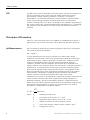
Explanation:
!
This symbol is located on the inside of the instrument:
"Refer to the Operator’s Manual / Service Manuals".
Symbol for instrument type B:
An instrument of the B-type falls under safety categories I, II or III, or has an internal
power supply, providing the required insulation against discharge current and reliable ground
connections.
- Important Information! - Important Information! -
- Operating Safety Information • The instrument falls under Safety Category I.
• The instrument belongs to Type B.
• The instrument is designed as a conventional device (of closed, not waterproof type).
• Do not operate the instrument in an explosive environment or in the vicinity of explosive
anesthetic mixtures containing oxygen or nitrous oxide.
• The instrument is suitable for continous operation.
CAUTION:
• The mains plug may be plugged only into a grounded socket. When using an extension cord, make
sure it is properly grounded.
• Any rupture of the ground lead inside or outside the instrument or a loose ground connection can
render hazardous operation of the instrument. Intentional disconnection of the grounding is not
permitted.
• While changing the fuses, make sure that the fuses used, are of the specified type and rating in
every case. Never use repaired fuses or short-circuit the fuse holders.
- Operating Safety Information -
Contents
Contents
METHOD SHEET
Intended Use .....................................................................................................................................1
Clinical Significance .........................................................................................................................1
Principles of Procedure .....................................................................................................................2
Reagents ans Accessories ..................................................................................................................5
Specimen Collection and Handling.............................................................................................. ......9
Handling and Storage of Samples ................................................................................................... 11
Materials Needed ............................................................................................................................ 12
Test Conditions ............................................................................................................................... 13
Calculated Values ........................................................................................................................... 14
Specific Performance Characteristics ............................................................................................. 17
Bibliography ................................................................................................................................... 26
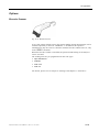
1 INTRODUCTION
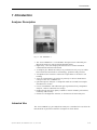
Analyzer Description .....................................................................................................................1-1
Intended Use ..................................................................................................................................1-1
Clinical Significance ......................................................................................................................1-2
Handling the Analyzer ...................................................................................................................1-3
Handling Blood and Blood Products ..............................................................................................1-3
Handling AVL Reagents.................................................................................................................1-4
Decontamination ............................................................................................................................1-5
Handling the Electrodes .................................................................................................................1-8
Operator’s Manual, AVL COMPACT 3, Rev. 2.0, June 1998
I
Contents
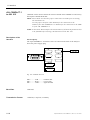
2 DESCRIPTION OF THE ANALYZER
Main Features................................................................................................................................ 2-1
Analyzer Components .................................................................................................................... 2-2
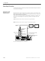
Description of the Sample Path...................................................................................................... 2-6
Operator Interface....................................................................................................................... 2-12
3 INSTALLATION, SHUTDOWN
Installation .................................................................................................................................... 3-1
Shutdown ..................................................................................................................................... 3-11
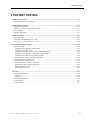
4 PATIENT TESTING
Sample Preparation ....................................................................................................................... 4-1
Sample Measurement ..................................................................................................................... 4-2
Password Option.......................................................................................................................... 4-10
Parameter and Data Input ........................................................................................................... 4-12
Printout ....................................................................................................................................... 4-19
5 QUALITY CONTROL
QC Measurement ........................................................................................................................... 5-1
QC Edit Function........................................................................................................................... 5-3
QC Statistics .................................................................................................................................. 5-7
II
Operator’s Manual, AVL COMPACT 3, Rev. 2.0, June 1998
Contents
6 CALIBRATION
Automatic Calibrations ..................................................................................................................6-1
Conditioning ..................................................................................................................................6-2
Operator-Initiated Calibrations.....................................................................................................6-2
7 DATA MANAGER
8 SYSTEM FUNCTIONS
Manual Standby .............................................................................................................................8-3
Automatic Standby.........................................................................................................................8-4
Timings ..........................................................................................................................................8-5
Parameter ......................................................................................................................................8-9
Language......................................................................................................................................8-13
Interface ......................................................................................................................................8-14
Password ......................................................................................................................................8-19
Device Lock..................................................................................................................................8-21
Report ..........................................................................................................................................8-22
Display .........................................................................................................................................8-27
Mini Sample .................................................................................................................................8-28
9 MAINTENANCE
Introduction ...................................................................................................................................9-1
Decontamination ............................................................................................................................9-1
Daily Maintenance .........................................................................................................................9-5
Weekly Maintenance ......................................................................................................................9-8
Operator’s Manual, AVL COMPACT 3, Rev. 2.0, June 1998
III
Contents
Every 6 Month ............................................................................................................................... 9-9
Yearly Maintenance..................................................................................................................... 9-10
As needed..................................................................................................................................... 9-11
10 TROUBLESHOOTING
Displayed and Printed Warning................................................................................................... 10-1
Displayed and Printed Alarms ..................................................................................................... 10-1
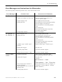
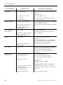
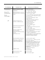
Error Messages and Instructions for Elimination........................................................................ 10-3
Printed Warnings and Error Messages ........................................................................................ 10-8
Insufficient Wash and Dry Cycle ................................................................................................. 10-8
Clogged Sample Path ................................................................................................................... 10-9
Test Programs............................................................................................................................ 10-13
11 INTERFACE
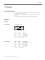
General Description ..................................................................................................................... 11-1
Hardware..................................................................................................................................... 11-1
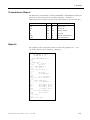
Baud Rate .................................................................................................................................... 11-2
Transmission Format ................................................................................................................... 11-2
Transmission Report.................................................................................................................... 11-3
Reports ........................................................................................................................................ 11-3
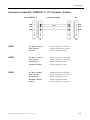
Connection Cable AVL COMPACT 3 - PC (Terminal / Printer) ................................................. 11-5
Barcode Scanner .......................................................................................................................... 11-6
Datalink ....................................................................................................................................... 11-8
Telelink ...................................................................................................................................... 11-23
IV
Operator’s Manual, AVL COMPACT 3, Rev. 2.0, June 1998
Contents
12 APPENDIX
Specification of the Analyzer .......................................................................................................12-1
Description of Various Reports ....................................................................................................12-4
Parameters and Equations ......................................................................................................... 12-15
Care and Maintenance of Remembranable Blood Gas Electrodes.............................................. 12-28
Operating Principles .................................................................................................................. 12-44
Analytical Performance ..............................................................................................................12-4/
Options ...................................................................................................................................... 12-59
User Programs ........................................................................................................................... 12-63
Fluidics ...................................................................................................................................... 12-64
13 PREANALYTICAL REQUIREMENTS FOR BLOOD GAS
ANALYSIS
Introduction .................................................................................................................................13-1
Sample Types ...............................................................................................................................13-1
Sampling Procedures....................................................................................................................13-2
Treatment of Sample before Analysis........................................................................................... 13-9
Summary .................................................................................................................................... 13-10
Operator’s Manual, AVL COMPACT 3, Rev. 2.0, June 1998
V
Contents
Figures
CHAPTER 2
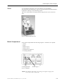
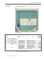
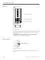
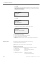
Fig. 2-1: Display ............................................................................................................................. 2-2
Fig. 2-2: Thermal printer................................................................................................................ 2-2
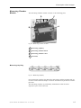
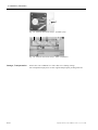
Fig. 2-3: View with open top cover ................................................................................................. 2-3
Fig. 2-4: Reagents ........................................................................................................................... 2-3
Fig. 2-5: Sample fill module ............................................................................................................ 2-5
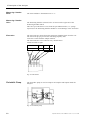
Fig. 2-6: Measuring chamber module ............................................................................................. 2-7
Fig. 2-7: Measuring capillary ......................................................................................................... 2-7
Fig. 2-8: Electrodes......................................................................................................................... 2-8
Fig. 2-9: Peristaltic pump ............................................................................................................... 2-8
Fig. 2-10: Rear panel ...................................................................................................................... 2-9
Fig. 2-11: Warning and identification plates .................................................................................. 2-9
Fig. 2-12: Interface ....................................................................................................................... 2-10
Fig. 2-13: Gas connections ............................................................................................................ 2-10
Fig. 2-14: Power switch module .................................................................................................... 2-11
CHAPTER 3
Fig. 3-1: Solenoid valve relief clamps - fill module ......................................................................... 3-2
Fig. 3-2: Solenoid valve relief clamps - peristaltic pump ................................................................ 3-3
Fig. 3-3: Solenoid valve relief clamps - bottle compartment ........................................................... 3-3
Fig. 3-4: Peristaltic pump tubes ...................................................................................................... 3-3
Fig. 3-5: Gas connection ................................................................................................................. 3-5
Fig. 3-6: Position of calibration gas cylinder .................................................................................. 3-5
Fig. 3-7: Removal of transport housing .......................................................................................... 3-6
VI
Operator’s Manual, AVL COMPACT 3, Rev. 2.0, June 1998
Contents
Fig. 3-8: pH Reference Electrode - yellow marking ........................................................................3-6
Fig. 3-9: pH Reference Electrode - droplet .....................................................................................3-9
Fig. 3-10: Paper insertion .............................................................................................................3-10
Fig. 3-11: Transport housing ........................................................................................................3-13
Fig. 3-12: Solenoid valve relief clamps - fill module......................................................................3-13
Fig. 3-13: Solenoid valve relief clamps - peristaltic pump.............................................................3-14
Fig. 3-14: Solenoid valve relief clamps - bottle compartment........................................................3-14
CHAPTER 4
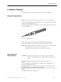
Fig. 4-1: AVL Microsampler ...........................................................................................................4-1
Fig. 4-2: Syringe measurement ........................................................................................................4-2
Fig. 4-3: Capillary measurement .....................................................................................................4-4
CHAPTER 8
Fig. 8-1: Password-codecards with different access codes.............................................................8-20
Fig. 8-2: Password.........................................................................................................................8-21
CHAPTER 9
Fig. 9-1: Paper insertion .................................................................................................................9-6
Fig. 9-2: Position of the gas cylinders .............................................................................................9-6
Fig. 9-3: pH Reference Electrode ....................................................................................................9-8
Fig. 9-4: Peristaltic pump tubes ....................................................................................................9-10
Fig. 9-5: Pump spool .....................................................................................................................9-11
Fig. 9-6: Zero-maintenance pH / Blood Gas Electrodes ................................................................9-12
Fig. 9-7: pH Reference Electrode (1).............................................................................................9-12
Operator’s Manual, AVL COMPACT 3, Rev. 2.0, June 1998
VII
Contents
Fig. 9-8: pH Reference Electrode.................................................................................................. 9-14
Fig. 9-9: Remove pH Reference Electrode housing ....................................................................... 9-14
Fig. 9-10: O-ring (pH Reference Electrode) .................................................................................. 9-15
Fig. 9-11: pH Reference Electrode housing................................................................................... 9-15
Fig. 9-12: Remembranable pH / Blood Gas Electrode ................................................................... 9-16
Fig. 9-13: Electrode check (1) - PCO 2 / PO 2 Electrode.................................................................. 9-16
Fig. 9-14: Electrode Check (2) - PCO 2 / PO 2 Electrode................................................................. 9-17
CHAPTER 10
Fig. 10-1: Remove glass splinters (1) .......................................................................................... 10-11
Fig. 10-2: Remove glass splinters (2) .......................................................................................... 10-11
Fig. 10-3: Remove glass splinters (3) .......................................................................................... 10-12
Fig. 10-4: Remove glass splinters (4) .......................................................................................... 10-12
CHAPTER 11
Fig. 11-1: COM 1 / COM 2 - pinning ............................................................................................ 11-1
Fig. 11-2: COM 3 - pinning........................................................................................................... 11-2
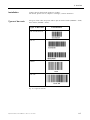
Fig. 11-3: Barcode scanner ........................................................................................................... 11-6
Fig. 11-4: 9-pin SUBMIN D / M .................................................................................................... 11-6
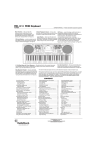
Fig. 11-5: Types of barcode .......................................................................................................... 11-7
Fig. 11-6: Interface AVL 988-3 ..................................................................................................... 11-8
Fig. 11-7: Interface AVL 9180 .................................................................................................... 11-14
Fig. 11-8: Interface AVL 912 ...................................................................................................... 11-20
Fig. 11-9: Telelink....................................................................................................................... 11-23
VIII
Operator’s Manual, AVL COMPACT 3, Rev. 2.0, June 1998
Contents
CHAPTER 12
Fig. 12-1: Remembranable pH / Blood Gas Electrode ................................................................. 12-28
Fig. 12-2: pH Electrode ............................................................................................................... 12-29
Fig. 12-3: Pull out the pH Electrode ........................................................................................... 12-29
Fig. 12-4: Remove pH Electrode housing .................................................................................... 12-30
Fig. 12-5: Inner electrode - O-Ring ............................................................................................. 12-30
Fig. 12-6: pH Electrode: fix new housing (1)............................................................................... 12-30
Fig. 12-7: pH Electrode: fix new housing (2)............................................................................... 12-31
Fig. 12-8: pH Electrode: immerse into Buffer 1 .......................................................................... 12-31
Fig. 12-9: pH Electrode: cleaning procedure (1) ......................................................................... 12-32
Fig. 12-10: pH Electrode: cleaning procedure (2) ....................................................................... 12-32
Fig. 12-11: pH Electrode: cleaning procedure (3) ....................................................................... 12-33
Fig. 12-12: pH Electrode: immerse into Buffer 1 ........................................................................ 12-33
Fig. 12-13: PCO 2 Electrode ......................................................................................................... 12-34
Fig. 12-14: PCO 2 Electrode: remove Inner element .................................................................... 12-35
Fig. 12-15: PCO 2 Electrode: Inner element ................................................................................. 12-35
Fig. 12-16: PCO 2 Electrode.: cleaning shaft ................................................................................ 12-35
Fig. 12-17: PCO 2 Electrode: inner shaft ..................................................................................... 12-36
Fig. 12-18: PCO 2 Electrode: cleaning procedure (1) ................................................................... 12-36
Fig. 12-19: PCO 2 Electrode: cleaning procedure (2) ................................................................... 12-37
Fig. 12-20: PCO 2 Electrode: cleaning procedure (3) ................................................................... 12-37
Fig. 12-21: PO 2 Electrode............................................................................................................ 12-38
Fig. 12-22: PO 2 Electrode: cleaning procedure (1) ...................................................................... 12-39
Fig. 12-23: PO 2 Electrode: cleaning procedure (2) ...................................................................... 12-39
Fig. 12-24: PO 2 Electrode: cleaning procedure (3) ...................................................................... 12-39
Fig. 12-25: Electrode housing with protective cap ...................................................................... 12-41
Fig. 12-26: Filling electrode housing with electrolyte ................................................................. 12-41
Operator’s Manual, AVL COMPACT 3, Rev. 2.0, June 1998
IX
Contents
Fig. 12-27: Remove air bubbles .................................................................................................. 12-42
Fig. 12-28: Insert inner part ....................................................................................................... 12-42
Fig. 12-29: Insert inner part ....................................................................................................... 12-42
Fig. 12-30: Close overflow hole of the electrode housing ............................................................ 12-43
Fig. 12-31: Silicon grease of the tip of the electrodes.................................................................. 12-43
Fig. 12-32: Operating principles - pH Electrode ......................................................................... 12-44
Fig. 12-33: pH Electrode............................................................................................................. 12-45
Fig. 12-34: pH Reference Electrode ............................................................................................ 12-45
Fig. 12-35: Operating principles - PCO 2 Electrode ..................................................................... 12-46
Fig. 12-36: PCO 2 Electrode......................................................................................................... 12-46
Fig. 12-37: Operating principles - PO 2 Electrode ....................................................................... 12-47
Fig. 12-38: PO 2 Electrode ........................................................................................................... 12-47
Fig. 12-39: Linearity of pH, PCO 2 and PO 2 in tonometered whole blood ................................... 12-57
Fig. 12-40: Comparison study with AVL 995 ............................................................................. 12-58
Fig. 12-41: Barcode scanner ....................................................................................................... 12-59
Fig. 12-42: External waste container .......................................................................................... 12-60
Fig. 12-43: User programs - AVL COMPACT 3 ......................................................................... 12-63
Fig. 12-44: Fluidics ..................................................................................................................... 12-64
CHAPTER 13
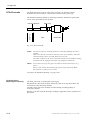
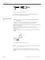
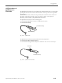
Fig. 13-1: AVL Microsampler ....................................................................................................... 13-2
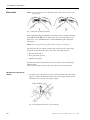
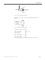
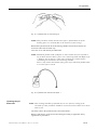
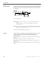
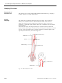
Fig. 13-2: Main arteries in the arm............................................................................................... 13-4
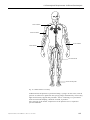
Fig. 13-3: Main arteries in the body ............................................................................................. 13-5
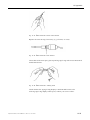
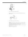
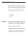
Fig. 13-4: Use of AVL Microsampler ............................................................................................ 13-6
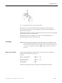
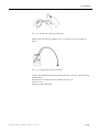
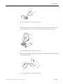
Fig. 13-5: Puncture of the heel (newborn) .................................................................................... 13-7
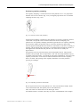
Fig. 13-6: Capillary puncture at the earlobe................................................................................. 13 -7
X
Operator’s Manual, AVL COMPACT 3, Rev. 2.0, June 1998
Method Sheet
Method Sheet
Intended Use ......................................................................................................................................1
Clinical Significance ..........................................................................................................................1
pH ...................................................................................................................................................1
P CO 2 ...............................................................................................................................................1
P O 2 .................................................................................................................................................2
Principles of Procedure ......................................................................................................................2
Reagents and Accessories ...................................................................................................................5
Specimen Collection and Handling............................................................................................... ......9
Safety ..............................................................................................................................................9
Sample Requirements .......................................................................................................................9
Anticoagulants .................................................................................................................................9
Sample Collection Devices ...............................................................................................................9
Handling and Storage of Samples .................................................................................................... 11
Whole Blood .................................................................................................................................. 11
Plasma ........................................................................................................................................... 11
Serum ............................................................................................................................................ 12
Materials Needed ............................................................................................................................. 12
Reagents ........................................................................................................................................ 12
Test Conditions ................................................................................................................................ 13
Sample Size ................................................................................................................................... 13
Sample Type .................................................................................................................................. 13
Sample Application ........................................................................................................................ 13
Ambient Temperature ..................................................................................................................... 13
Relative Humidity .......................................................................................................................... 13
Type of Measurement ..................................................................................................................... 13
Measured Values ............................................................................................................................ 13
Input Values................................................................................................................................... 14
Calculated Values........................................................................................................................... 14
Types of Calibration ....................................................................................................................... 15
Quality Control .............................................................................................................................. 15
Operator’s Manual, AVL COMPACT 3, Rev. 2.0, June 1998
I
Method Sheet
Specific Performance Characteristics .............................................................................................. 17
Limitations .................................................................................................................................... 17
Reproducibility .............................................................................................................................. 17
Precision and Linearity................................................................................................................... 20
Precision and Recovery on Whole Blood ......................................................................................... 21
Correlation to Other Methods ......................................................................................................... 23
Precision of Measurement in Whole Blood ...................................................................................... 23
Bibliography .................................................................................................................................... 26
II
Operator’s Manual, AVL COMPACT 3, Rev. 2.0, June 1998
Method Sheet
Method Sheet
Intended Use
The AVL COMPACT 3 pH/Blood Gas Analyzer is intended to be used for the
measurement of pH, P CO 2 and P O 2 in samples of whole blood.
Clinical Significance1
pH
The pH value of the blood, serum or plasma, may be the single most valuable
factor in the evaluation of the acid-base status of a patient. The pH value is an
indicator of the balance between the buffer (blood), renal (kidney) and respiratory
(lung) systems, and one of the most tightly controlled parameters in the body. The
causes of abnormal blood pH-values are generally classified as:
a) primary bicarbonate deficit - metabolic acidosis
b) primary bicarbonate excess - metabolic alkalosis
c) primary hypoventilation - respiratory acidosis
d) primary hyperventilation - respiratory alkalosis
An increase in blood, serum or plasma pH (alkalemia) may be due to increased
plasma bicarbonate, or a feature of respiratory alkalosis due to an increased
elimination of CO 2 due to hyperventilation.
A decreased pH value (acidemia) in blood, serum or plasma may occur due to an
increased formation of organic acids, an increased excretion of H + -ions in certain
renal disorders, an increased acid intake such as in salicylate poisoning or loss of
alkaline body fluids. Respiratory acidosis is the result of a decreased alveolar
ventilation and may be acute; as the result of pulmonary edema, airway obstruction
or medication, or maybe be chronic; as the result of obstructive or restrictive
respiratory diseases.
PCO 2
The P CO 2 value of arterial blood is used to assess how well the body eliminates
carbon dioxide in relation to the metabolic rate of CO 2 production. A P CO 2 below
the normal range is termed respiratory alkalosis and indicates hypocapnia, a
condition caused by increased alveolar ventilation such as hyperventilation. An
arterial P CO 2 above the normal range is termed respiratory acidosis and indicates
hypercapnia, a sign of hypoventilation and failure, resulting from cardiac arrest,
chronic obstructive lung disease, drug overdose, or chronic metabolic acid-base
disturbances.
1
Teitz, Norbert W., Ed., Clinical Guide to Laboratory Tests, 2nd Ed., (Philadelphia: W.B.Saunders, Co., 1990) p.436.
Operator’s Manual, AVL COMPACT 3, Rev. 2.0, June 1998
1
Method Sheet
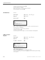
PO 2
The P O 2 value of arterial blood has become the primary tool for the evaluation of
arterial oxygenation status. Values below the normal arterial P O 2 (arterial
hypoxemia) are usually caused by pulmonary, circulatory, or respiratory
abnormalities (e.g. bronchial obstruction, vascular problems, decreased cardiac
output, increased oxygen demand, anatomical heart defect, low inspired O 2
content). Generally, P O 2 levels above 100 mmHg do not contribute significantly to
the oxygen content since, with normal hemoglobin concentrations, 80 - 100 mmHg
P O 2 provides a 97% saturation level, and a level greater than 100% cannot be
achieved.
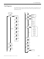
Principles of Procedure
There are 4 electrodes used in the AVL COMPACT 3 pH/Blood Gas Analyzer; a
pH Electrode, a pH reference electrode, a P CO 2 Electrode and a P O 2 Electrode.
pH Measurement
pH of a solution is defined by the negative logarithm of the activity of Hydrogen
ions, and described by the equation:
pH = -log [ H + ]
A single measurement of the electric potential of a solution, under proper
conditions, can be directly related to the concentration of Hydrogen ions. In pH
measurement systems, a bulb of special glass is filled with a conductive buffer
solution of known pH in contact with the measuring instrument through a
conductive, metallic electrode. When this special electrode is immersed in an
aqueous solution, water molecules diffuse into the structure of the glass and form a
hydrated layer. A potential difference develops between the solution inside the
glass electrode and the solution being measured for [H + ]. The magnitude of this
difference depends solely on the concentration of Hydrogen ions in the solution.
This difference is measured by combining the glass electrode with standard,
calomel, reference electrode and measuring the voltage of the system.
Calibration of the system is accomplished by using buffer solutions with known pH
values traceable to buffers with values assigned by the National Institute of
Standard Technology. The pH of the unknown solution is compared to known
buffer solution by electric potential measurement by the instrument using specially
designed electrodes arranged as a special type of concentration cell which is
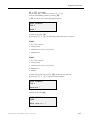
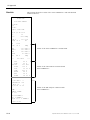
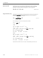
described by a modification of the Nernst equation:
E = E0 +
where:
RT
lna H + (mv)
nF
E0
=
standard potential in mV
R
=
gas constant (8.3143 joule × K -1 × mol -1 )
T
=
temperature degrees Kelvin (310.15 °K = 37 °C)
n
=
number of electrons in electrochemical reaction
F
=
value of the Faraday constant (96487 coulomb × mol -1 )
aH+ =
2
Hydrogen ion activity
Operator’s Manual, AVL COMPACT 3, Rev. 2.0, June 1998
Method Sheet
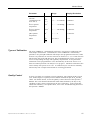
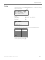
pH Electrode
pH Reference
Electrode
PCO 2
The pH Electrode consists of a single glass tube with a special pH-sensitive glass
membrane at its tip. Hydrogen ions in a sample at the time diffuse into the
hydrated glass layer and generate an electric potential. This potential is conducted
through a gelled buffer solution of constant pH to the instrument through an AgCl
coated silver pin immersed in the buffer and connected to the instrument with a
cable and plug. The electrical circuit is completed through the sample path to the
pH Reference Electrode and a second instrument input. The potential difference
(measuring voltage) is amplified for easier processing. With the help of a
calibration curve determined by calibration points near 7.38 and 6.84, and by
using the measured voltage of the sample, the ion concentration of the sample is
determined and converted to pH for display.
The pH Reference Electrode consists of a glass tube filled with calomel paste
(mercurous chloride) in contact with mercury surrounding a platinum wire. This
mixture is kept moist with a cotton plug at the end of the glass tube immersed in a
solution of potassium chloride (KCl) and contained in a disposable housing. The
mixture of metals in the electrode generates a constant voltage. A porous
membrane at the tip of the housing provides a liquid junction with the sample and
the KCl solution serves as a salt bridge, establishing contact between the
instrument, calomel element and pH Electrode through the sample in contact with
the KCl at the housing tip.
The P CO 2 Electrode consists of a pH-glass electrode and an Ag/AgCl reference
electrode that forms the outer part that is surrounded by a common electrolyte
solution. They are separated from the sample or calibration gas by a CO2
permeable but not ion-permeable membrane. Carbon dioxide diffuses in both
directions through the membrane until an equilibrium is established between the
CO 2 partial pressure of the sample and the CO 2 partial pressure of the very thin
electrolyte layer between the membrane and the glass electrode. At this time, the
pH-value of the electrolyte solution has been changed by a chemical reaction,
which occurs as carbon dioxide gas dissolves in the electrolyte and produces
hydrogen ions.
CO 2 + H 2 O ⇔ H 2 CO 3 ⇔ H + + HCO 3 −
This pH change is measured and amplified and is indicated as the P CO 2 value.
Methodology is a modification of the galvanometric pH measurement.
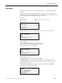
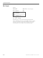
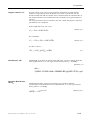
PO 2
The P O 2 Electrode consists of a glass electrode body containing the cathode
(4 platinum wires) and a silver anode, an electrode housing containing an O 2 permeable membrane and inner electrolyte that enables the chemical reaction
and transports the charges. The O 2 diffuses through the membrane, depending
on the O 2 partial pressure of the sample, and continuously replaces the O 2
Operator’s Manual, AVL COMPACT 3, Rev. 2.0, June 1998
3
Method Sheet
molecules of the electrolyte layer consumed during the cathode reaction. A
very small constant current, representing the oxygen partial pressure P O 2 of the
samples passes through the electrode.
Methodology is polarographic. At the cathode, oxygen diffused through the
membrane is reduced through a series of reactions producing current between the
cathode and anode proportionate to the oxygen tension:
O 2 + 2H 2 O + 4e − → 4OH −
4NaCl + 4OH − → 4NaOH + 4Cl −
Cathode Reaction
Electrolyte Reaction
4Ag → 4Ag + + 4e − → 4Cl − + 4Ag + → 4AgCl + 4e −
Anode Reaction
The electrons in the initial reaction are supplied by a constant voltage of
-0.7 V. In this series of equations, it is apparent that for the reduction of each
oxygen molecule, 4 electrons are consumed.
4
Operator’s Manual, AVL COMPACT 3, Rev. 2.0, June 1998
Method Sheet
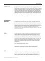
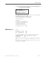
Reagents and Accessories
Buffer Type 1
(pH=7.383)
Buffer Type 2
(pH=6.841)
pH Reference
Solution
Order number:
BP0136
Use:
For calibration of pH in AVL pH/Blood Gas instruments
Contents:
1 package contains 3 ready to use containers with 90 mL
each
Composition:
Potassium dihydrogen phosphate, 13.619 mmol/L
Disodium hydrogen phosphate, 53.14 mmol/L
Lithium carbonate, 0.25 mmol/L
Additives:
Germicides
Storage:
Temperature: 5 - 30 °C (41 - 86 °F)
Stability:
Expiration date and lot number are printed on each container
label
Order number:
BP0137
Use:
For calibration of pH in AVL pH/Blood Gas instruments
Contents:
1 package contains 3 ready to use containers with 90 mL
each
Composition:
Potassium dihydrogen phosphate, 25.0 mmol/L
Disodium hydrogen phosphate, 25.0 mmol/L
Additives:
Germicides
Storage:
Temperature: 5 - 30 °C (41 - 86 °F)
Stability:
Expiration date and lot number are printed on each container
label
Order number:
BP0134
Use:
For calibration of pH in AVL pH/Blood Gas instruments
Contents:
1 package contains 3 ready to use containers with 90 mL
each
Composition:
Potassium chloride, 600 mmol/L
Additives:
Germicides
Storage:
Temperature: 5 - 30 °C (41 - 86 °F)
Stability:
Expiration date and lot number are printed on each container
label
Operator’s Manual, AVL COMPACT 3, Rev. 2.0, June 1998
5
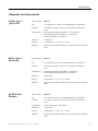
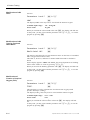
Method Sheet
Rinse
Cleaning Solution
Deproteinizer
6
Order number:
BP1890
Use:
For calibration of pH in AVL pH/Blood Gas instruments
Contents:
1 package contains 6 ready to use containers with 430 mL
each
Composition:
Dehydran 241,0.065 g/L
Dehydol 100, 0.0065 g/L
Additives:
Germicides
Storage:
Temperature: 5 - 30 °C (41 - 86 °F)
Stability:
Expiration date and lot number are printed on each package
Order number:
BP1889
Use:
For the daily cleaning of the AVL COMPACT 3 measuring
system
Contents:
1 package contains 3 ready to use containers with 90 mL each
Composition:
Sodium bicarbonate, 4.1 g/L
Sodium chloride, 2.5 g/L
Antarox BL344, 1.0 g/L
2-phenylethanol, 0.1 g/L
Hyamine 1622, 0.05 g/L
Storage:
Temperature: 5 - 30 °C (41 - 86 °F)
Stability:
Expiration date and lot number are printed on each package
Order number:
BP0521
Use:
For periodic cleaning of the measuring system after lipemic
samples or as required for decontamination.
Contents:
Each dispensing bottle contains 100 mL of solution.
Composition:
Sodium hypochlorite, 16.0 g/L
Storage:
Temperature: 5 - 30 °C (41 - 86 °F)
Stability:
Expiration date and lot number are printed on each container
label.
Operator’s Manual, AVL COMPACT 3, Rev. 2.0, June 1998
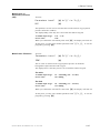
Method Sheet
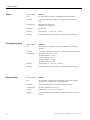
PCO 2 Filling
Solution
PO 2 Filling Solution
Calibration Gas 1
Order number:
BP1286
Use:
Electrolyte solution used in remembranable P CO 2
Electrodes.
Contents:
Each dispensing bottle contains 100 mL of solution.
Composition:
Potassium chloride, 25.0 mmol/L
Sodium bicarbonate, 10.0 mmol/L
Additives:
Germicides
Storage:
Temperature: 5 - 30 °C (41 - 86 °F)
Stability:
Expiration date and lot number are printed on each container
label.
Order number:
BP1414
Use:
Electrolyte solution used in remembranable P O 2 Electrodes.
Contents:
Each dispensing bottle contains 100 mL of solution.
Composition:
Ethylene glycol: 1000 g/L
Regent grade water: 100 g/L
Disodium hydrogen phosphate: 5.34 g/L
Potassium dihydrogen phosphate: 2.45 g/L
Sodium chloride: 0.58 g/L
Additives:
Germicides
Storage:
Temperature: 5 - 30 °C (41 - 86 °F)
Stability:
Expiration date and lot number are printed on each container
label.
Order number:
HL0020
Use:
For the calibration of P O 2 and P CO 2 in the AVL COMPACT 3
pH/Blood Gas Analyzer
Contents:
Each disposable cylinder contains 3.15 L at 2200 PSI at 70 °F
(150 bar at 21°C)
Composition:
Oxygen: 20.0% ± 0.03%
Carbon Dioxide: 5.5% ± 0.03%
Nitrogen: balance
Storage:
Temperature: 5 - 30 °C (41 - 86 °F)
Stability:
Expiration date and lot number are printed on each container
label
Operator’s Manual, AVL COMPACT 3, Rev. 2.0, June 1998
7
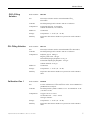
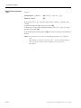
Method Sheet
Calibration Gas 2
Capillary Tubes
Order number:
HL0021
Use:
For the calibration of P O 2 and P CO 2 in the AVL COMPACT
3 pH/Blood Gas Analyzer
Contents:
Each disposable cylinder contains 3.15 L at 2200 PSI at
70 °F (150 bar at 21°C)
Composition:
Carbon Dioxide: 10.0% ± 0.03 %
Nitrogen: balance
Storage:
Temperature: 5 - 30 °C (41 - 86 °F)
Stability:
Expiration date and lot number are printed on each container
label
Order number:
MG0002
Use:
For collection and transport of capillary blood specimens for
pH/Blood Gas and Electrolyte analysis. Not to be used for
collection of samples for analysis of Lithium
Contents:
Each package contains 250 capillary tubes
Composition:
Each tube is coated to contain 6 I.U. Sodium heparin and
9 I.U. Lithium heparin per 100 µL tube volume. Each tube has
a minimum volume of 115µL
Storage:
Temperature: 5 - 30 °C (41 - 86 °F)
Stability:
Expiration date and lot number are labeled on the bottom of
each container
Precautions: Use of calibration solutions or electrodes not manufactured for AVL
could void the warranty.
A waste container is provided. Once used, the waste container holds
human body fluids which may be potentially infectious; handle with
appropriate care to avoid skin contact or ingestion.
For in-vitro diagnostic use.
8
Operator’s Manual, AVL COMPACT 3, Rev. 2.0, June 1998
Method Sheet
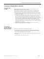
Specimen Collection and Handling
Safety
Sample
Requirements
Anticoagulants
Universal precautions must be observed when collecting blood specimens. It is
recommended that all blood specimens be handled as if capable of transmitting
human immunodeficiency virus (HIV), hepatitis B virus (HBV), or other
bloodborne pathogens. Proper blood collection techniques must be followed in
order to minimize risk to the laboratory staff, and gloves should be worn. Please
refer to NCCLS document M29-T2, Protection of Laboratory Workers from
Infectious Disease Transmitted by Blood, Body Fluids, and Tissue - Second
Edition; Tentative Guideline for further information on safe handling of these
specimens.
Refer to NCCLS document H11-A2, Percutaneous Collection of Arterial Blood for
Laboratory Analysis - Second Edition; Approved Standard, May 1992, for detailed
information of sample collection, storage and handling.
Blood sampling for analysis must be performed under proper medical supervision
with details of collection, including sampling devices, site selection, sample
handling, documentation and specific procedures used approved by the personnel
responsible.
Lithium heparin, Sodium heparin or balanced heparin salts (as often used for
samples taken also for electrolyte analysis) are the only acceptable anticoagulants
for blood gas analysis. Other anticoagulants such as EDTA, citrate, oxylate and
fluoride have a significant effect on blood pH and should not be used. Lithium
heparin should not be used for samples taken also for analysis of Lithium.
Sample Collection
Devices
Syringes
If liquid heparin is used as an anticoagulant, collection devices should be no
larger than the amount of blood required minimizing the effects of dilution of
the blood by the anticoagulant solution. Although plastic syringes are
commonly used for collection of blood specimens for blood gas analysis,
there have been reports in the literature regarding the use of plastic syringes
when P O 2 values higher than normal are expected. Particular attention should
be paid to cooling blood samples in ice water, because of the CO 2 and oxygen
solubility in some plastics. If blood specimens are expected to have very high
P O 2 values, care should be taken to analyze the specimen as quickly as
possible following collection to avoid the need for cooling.
Operator’s Manual, AVL COMPACT 3, Rev. 2.0, June 1998
9
Method Sheet
Capillary Tubes
Capillary blood specimens should be collected using AVL capillary tubes,
which have a minimum volume, filled, of 115 µL and are ideally suited for
use with the AVL COMPACT 3. The AVL capillary tubes for pH and blood
gas analysis should not be used for samples taken for the analysis of Lithium.
Samples may be collected in capillary tubes after warming the area or
otherwise stimulating it to promote arterial circulation before the puncture.
The puncture should be made deeply enough to ensure a free and rapid flow
of blood.
Do not use clay-capped capillary tubes as the rough, broken edge left when
the capillary is cut may cause damage to the AVL COMPACT 3 fill port. Use
only capillary tubes with fire-polished ends to prevent damage to the
instrument. If a mixing flea is used, as required in some capillary tubes, take
care to remove the flea prior to sample introduction to avoid damage to the
AVL COMPACT 3.
Specimens collected in capillary tubes are stable at room temperature for up
to 30 minutes after collection because of the rapid cooling of the sample
accomplished during filling.
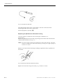
AVL Microsampler
Blood may be collected for analysis on the AVL COMPACT 3 with the
AVL Microsampler to provide two filled capillary tubes which may be used for
analysis on separate instruments for split-sampling, for CO-Oximetry measurement
or for the analysis of electrolytes other than Lithium.
After collection, the AVL Microsampler should be capped and transported in a
horizontal position to the instrument for analysis within 30 minutes, as with all
specimens collected in capillary tubes.
Vacuum Tubes
Venous specimens collected in vacuum tubes containing Lithium or Sodium
heparin may be used. Ensure that the tube is completely filled and that the sample
is thoroughly mixed immediately after collection by gentle inversion. Blood gas
values reported from venous specimens should be clearly identified as such to
allow for correct interpretation.
Each laboratory should determine the acceptability of its own blood collection
syringes and capillaries. Variations in these products exist between manufacturers,
and at times, from lot to lot.
10
Operator’s Manual, AVL COMPACT 3, Rev. 2.0, June 1998
Method Sheet
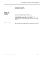
Handling and Storage of Samples
Please refer to NCCLS Document C27-A, Blood Gas Pre-Analytical
Considerations: Specimen Collection, Calibration and Controls; Approved
Guideline, April 1993 for a detailed discussion of guidelines for the collection of
acceptable specimens, instrument calibration, and quality control in pH and blood
gas analysis; including details of many potential sources of error which may cause
inaccurate results.
Whole Blood
Arterial Specimens
Whole blood samples should be collected in a heparinized syringe, AVL
Microsampler or capillary and analyzed as soon as possible after collection.
Immediately after collection, check the syringe or other device for air bubbles and
carefully expel any trapped bubbles, following the manufacturer’s recommended
procedure. Extreme caution should be used to avoid needle stick injury. Mix the
specimen collected in a syringe thoroughly with anticoagulant by gentle inversion
or by rolling the syringe between both hands. Properly identify the specimen,
following usual procedures for such documentation. Place the syringe containing
the specimen in an ice slurry. Blood gases and pH will change if the specimen
remains at room temperature in a syringe for more than 5 minutes due to cellular
metabolism. P O 2 changes due to oxygen consumption may be influenced by
several factors, including white blood cell count, reticulocyte count, storage
temperature and initial P O 2 value. At a storage temperature of 1 to 5 °C, the
results obtained are valid up to 2 hours. Samples expected to have high white
blood cell count, reticulocyte count, or high P O 2 values initially should be
analyzed as soon as possible after collection.
Errors in blood gas analysis on properly collected samples may result from
improper mixing of the sample after collection and before measurement;
contamination with room air resulting from failure to expel trapped bubbles after
collection; and from metabolic changes in the sample.
Venous Specimens
Whole blood samples should be collected in a heparinized syringe, vacuum tube or
capillary and analyzed as soon as possible after collection. The sample container
should be filled as much as possible, leaving minimal residual air space. If storage
for more than 5 minutes or up to 1 hour is required, the sample should be stored,
cooled in an ice slurry (1 to 4 ºC) prior to analysis.
Plasma
Plasma samples should be obtained by immediately centrifuging heparinized whole
blood, separating the plasma from red cells and capping the sample tube. Analyze
as soon as possible. If storage is required, the samples should be capped and
refrigerated at 4 to 8 °C. Refrigerated samples should be allowed to warm to room
temperature (15 to 32 °C / 50 to 90 °F) prior to analysis. Plasma samples more
than one hour old must be centrifuged again to remove additional fibrin clots.
Operator’s Manual, AVL COMPACT 3, Rev. 2.0, June 1998
11
Method Sheet
Serum
Serum samples should be obtained by collecting blood in an untreated blood
collecting tube. The sample should stand for 30 minutes to allow the clot to form
prior to centrifugation. After centrifugation, remove the serum from the clot, and
cap or seal the sample tube. If storage is required, the sample should be stored,
tightly capped, under refrigeration at 4 to 8 °C (39 to 46 °F), and allowed to return
to room temperature, 15 to 32 °C (59 to 90 °F), prior to analysis.
Each laboratory should determine the acceptability
of its own blood collection syringes, capillaries and tubes and the serum or plasma
separation products. Variations in these products exist between manufacturers, and
at times, from lot to lot.
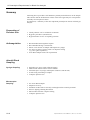
Materials Needed
Reagents
Description
Part Number
pH Buffer Type 1
BP0136
pH Buffer Type 2
BP0137
pH Reference Solution
BP0134
Rinse
BP1890
Cleaning Solution
BP1887
Deproteinizer
BP0521
Calibration Gas 1
HL0020
Calibration Gas 2
HL0021
Printer Paper
HP0070
The AVL COMPACT 3 pH/Blood Gas Analyzer automatically processes the
sample through the necessary steps, then prints and displays the results. For
details of this operation, please refer to the Operator’s Manual.
12
Operator’s Manual, AVL COMPACT 3, Rev. 2.0, June 1998
Method Sheet
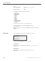
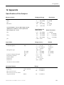
Test Conditions
Sample Size
50 µ L, capillary
100 µ L, syringe
25 µ L, microsample mode
Sample Type
whole blood
Sample Application
syringe, capillary or AVL Microsampler
Ambient
Temperature
15 - 32º C (59 - 89.6º F)
Relative Humidity
20% to 90% (non-condensing)
Type of
Measurement
Measured Values
pH, P CO 2
PO2
galvenometric
polarographic
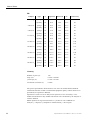
Parameter
Range
Display Resolution
pH
6.0 to 8.0 pH units
0.001 pH units
P CO 2
0 to 200 mmHg
0.1 mmHg
0.5 - 26.7 kPa
0.01 kPa
-10 to 742 mmHg
0.1 mmHg
-1.33 to 98.7 kPa
0.01 kPa
300 to 800 mmHg
0.1 mmHg
0.0 to 106.0 kPa
0.01 kPa
PO2
Barometric Pressure
Operator’s Manual, AVL COMPACT 3, Rev. 2.0, June 1998
13
Method Sheet
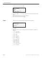
Input Values
Parameter
Range
Display Resolution
Patient temperature, T
14.0 to 44.0 °C
0.1 °C
57.1 to 111.2 °F
0.1 °F
1 to 26 g/dL
0.1 g/dL
10 to 260 g/L
1.0 g/L
0.7 to 16.1 mmol/L
0.01 mmol/L
Total Hemoglobin, tHb
Hemoglobin type
adult or fetal
P 50 adult
15 to 40 mmHg
0.1 mmHg
2.0 to 5.33 kPa
0.01 kPa
10 to 40 mmHg
0.1 mmHg
1.34 to 5.33 kPa
0.01 kPa
Respiratory Quotient, RQ
0.71 to 1.99
0.01
Fraction of Inspired
Oxygen F IO 2
0.11 to 0.99
0.01
Patient number
0 to 9999999999
Patient age
0 to 99 years
Patient sex
male or female
P 50 fetal
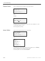
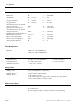
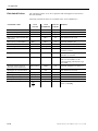
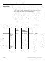
Calculated Values
Parameter
Range
Display Resolution
1 to 100 mmol/L
0.1 mmol/L
Actual Bicarbonate
HCO 3
Base Excess,
BE
-40 to +40 mmol/L
0.1 mmol/L
Base Excess ecf,
BE ecf
-40 to +40 mmol/L
0.1 mmol/L
Base Excess at actual
oxygen saturation
BE act
-40 to +40 mmol/L
0.1 mmol/L
Total CO 2 ,
1 to 100 mmol/L
0.1 mmol/L
1 to 100 mmol/L
0.1 mmol/L
6.5 to 8.0
0.001 pH units
10 to 1000 nmol/L
0.1 nmol/L
Standard
Bicarbonate,
ctCO 2
-
Standard pH,
14
-
1 year
HCO 3
st
pH st
+
Hydrogen ion
concentration
cH
Functional Oxygen
saturation,
SO2
0 to 100 %
0.1%
Oxygen content,
ctO 2
0 to 56 mL/dL
0.1 mL/dL
Alveolar arterial
oxygen partial
pressure difference,
AaDO 2
0 to 742 mmHg
0.1 mmHg
Operator’s Manual, AVL COMPACT 3, Rev. 2.0, June 1998
Method Sheet
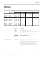
Parameter
Standardized ionized
Calcium
niCa
(at Datalink with
pH=7.4
AVL 988-3)
Range
Display Resolution
0.1 ....... 6.0 mmol/L
0.1mmol/L
P O 2 at patient
temperature
PO2t
0 .......... 742 mmHg
0.1 mmol/L
P CO 2 at patient
temperature
P CO 2 t
0 .......... 200 mmHg
0.1 mmol/L
pH at patient
temperature
pH t
6 .......... 8
0.1 mmol/L
Shunt
&
Qs
&
Qt
0 to 100 %
0.1%
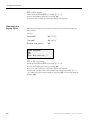
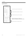
Types of Calibration
The AVL COMPACT 3 automatically performs a one-point gas calibration with
each sample measurement. In addition, the AVL COMPACT 3 automatically
performs a one-point pH calibration based upon user programmed intervals; either
fixed at every half hour or one hour intervals or flexible at 1, 2, or 3 hour intervals
based on the drift of the pH Electrode. The programmed interval may vary from
site to site depending on usage and regulatory requirements. A two-point main
calibration can be programmed to occur automatically at intervals from 2 to 12
hours in normal operation if no analysis is in progress. Automatic calibration also
occurs shortly after power-on or reset. A calibration cycle can also be manually
initiated any time a sample measurement is not being performed.
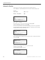
Quality Control
At least once daily or according to local regulations, run solutions at three levels
(low, normal, high) of a quality control solution with known pH, P CO 2 and P O 2
values. For further details, review the Quality Control Section of the Operator’s
Manual. The result obtained should fall within limits defined by the day to day
variability of the system as measured in the user’s laboratory. If the results fall
outside the laboratory’s acceptable limits, refer to the Troubleshooting Section of
the Operator’s Manual.
Operator’s Manual, AVL COMPACT 3, Rev. 2.0, June 1998
15
Method Sheet
Reference Interval
2
Laboratory normal ranges for arterial carbon dioxide tension, P aCO 2 and pH are
well documented and widely accepted:
Parameter
pH
P aCO 2 (mmHg)
± 2 SD
Mean
7.40
7.35 - 7.45
40
35 - 45
Arterial oxygen tension, P aO 2 is dependent upon the inspired oxygen tension, as
well as various physiologic variables, and the administration of oxygen is common
in the treatment of patients in need of blood gas analysis.
Hypoxemia is defined as an arterial P O 2 below an acceptable range while
breathing room air, with about 21% oxygen, at sea level. Increasing altitudes
above sea level will produce lower inspired oxygen tensions and therefore, lower
arterial P O 2 values.
Below are listed acceptable arterial oxygen tensions at sea level, while breathing
room air:
P aO 2
Adult and Child
Normal
Acceptable range
Hypoxemia
97 mmHg
> 80 mmHg
< 80 mmHg
Newborn
Acceptable range
40 - 70 mm Hg
Aged
Acceptable range
60
70
80
90
years
years
years
years
old
old
old
old
>
>
>
>
80
70
60
50
mmHg
mmHg
mmHg
mmHg
Each laboratory should establish its own reference interval for pH, P CO 2 and P O 2
as performed on the AVL COMPACT 3 Analyzer and at their laboratory altitude.
2
Shapiro BA, Harrison RA, Cane RD, Kozlowski-Templin R: Clinical Application of Blood Gases, 4th ed., (Chicago:
Year Bood Medical Publishers, Inc.,1991) pp 79-83.
16
Operator’s Manual, AVL COMPACT 3, Rev. 2.0, June 1998
Method Sheet
Specific Performance Characteristics
All performance data in this section was generated on AVL COMPACT pH/Blood
Gas systems with default calibration frequencies: continuous 1 point gas
calibration, 1 point pH calibration at 1, 2 or 3 hour intervals determined
automatically by the instrument based on calibration drift, and complete 2 point
calibration every 12 hours, and without any correlation factors. The operating
environment during the collection of this data was typical, varying from 22 to 26
°C (70 to 80 °F).
Limitations
The performance characteristics are affected by the following sample
considerations:
The preferred test liquid is whole, human blood for all parameters. It is necessary
to tonometer blood to obtain values to evaluate accuracy of P O 2 and P CO 2
because patient samples must be considered to be unknown. Tonometry of blood
introduces potential errors unrelated to the blood gas system being evaluated,
including: accuracy of the gas values used, temperature control and thermostatting
of the tonometer, humidification of the tonometry gases, duration of tonometry and
transfer of the sample from the tonometer to the instrument for analysis.
pH of blood cannot be predicted in tonometry. All tonometered samples analyzed
in these studies were analyzed in duplicate on an AVL 995 to establish correlation.
Precision of P O 2 and P CO 2 measurement, as well as pH was evaluated over a 20
day period using 2 AVL COMPACT pH/Blood Gas Analyzers with 2 replicates per
run and 2 runs per day using a commercially available solution of reduced bovine
hemoglobin which has been demonstrated to be comparable to tonometered whole
blood. 3
Precision and accuracy of pH was evaluated using commercially available
precision pH buffer solutions with values traceable to N.I.S.T. and precision of
pH, P CO 2 and P O 2 was evaluated using aqueous control materials.
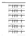
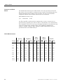
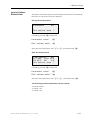
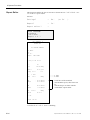
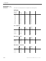
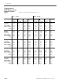
Reproducibility
Typical Within-Run (S wr ) and Total (S T ) imprecision data was collected from 2 runs
per day with 2 replicates per run on three AVL COMPACT pH/Blood Gas
Analyzers over twenty days following the protocol of NCCLS document number
EP5-T2.
Material: AVL CONFITEST III Aqueous pH/Blood Gas Control, Level 1
Parameter
n
Mean
S wr
ST
pH
P CO 2
PO2
240
240
240
7.207
18.8
148.7
0.0020
0.20
0.92
0.0043
0.27
1.72
3
Mahoney JJ, Wong RJ, Van Kessel AL: Reduced Bovine Hemoglobin Solution Evaluated for Use as a Blood Gas
Quality-Control Material. Clin.Chem.39/5, 874-879 (1993).
Operator’s Manual, AVL COMPACT 3, Rev. 2.0, June 1998
17
Method Sheet
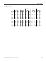
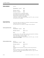
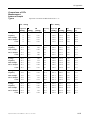
Material: AVL CONFITEST III Aqueous pH/Blood Gas Control, Level 2
Parameter
n
pH
P CO 2
PO2
240
240
240
Mean
7.410
37.4
110.9
S wr
ST
0.0017
0.23
0.93
0.0047
0.42
1.38
Material: AVL CONFITEST III Aqueous pH/Blood Gas Control, Level 3
Parameter
n
pH
P CO 2
PO2
240
240
240
Mean
7.630
63.4
74.1
S wr
ST
0.0021
0.34
0.78
0.0051
0.50
1.42
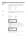
Material: AVL CONFITEST III Aqueous pH/Blood Gas Control, Level 4
Parameter
n
pH
P CO 2
PO2
240
240
240
Mean
7.406
44.3
288.6
S wr
ST
0.0012
0.25
1.93
0.0045
0.29
5.43
Material: RNA Medical QUALIDATA pH/Blood Gas Electrolyte
Control Level 1
Parameter
n
pH
P CO 2
PO2
240
240
240
Mean
7.144
70.3
72.3
S wr
ST
0.0016
0.55
0.70
0.0043
0.87
1.13
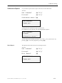
Material: RNA Medical QUALIDATA pH/Blood Gas Electrolyte
Control Level 2
Parameter
n
pH
P CO 2
PO2
240
240
240
Mean
7.395
44.5
110.8
S wr
ST
0.0016
0.24
0.89
0.0065
0.34
1.54
Material: RNA Medical QUALIDATA pH/Blood Gas Electrolyte
Control Level 3
18
Parameter
n
pH
P CO 2
PO2
240
240
240
Mean
7.596
23.0
150.3
S wr
ST
0.0013
0.18
0.93
0.0073
0.38
1.59
Operator’s Manual, AVL COMPACT 3, Rev. 2.0, June 1998
Method Sheet
Material: RNA Medical EQUIL Reduced Bovine Hemoglobin Blood
Tonometry Material 4
Level 1: :
11.0% CO 2 , 20.93% O 2 , balance N 2
Parameter
n
pH
P CO 2
PO2
240
240
240
Mean
7.178
74.2
149.2
S wr
ST
0.0015
0.58
1.19
0.0087
1.08
1.95
Level 2: : 5.13% CO 2 , 7.80% O 2 , balance N 2
Parameter
n
pH
P CO 2
PO2
240
240
240
Mean
7.422
34.6
56.5
S wr
ST
0.0017
0.28
0.75
0.0047
0.41
1.25
Level 2: : 1.50% CO 2 , 2.91% O 2 , balance N 2
Parameter
n
pH
P CO 2
PO2
240
240
240
Mean
7.732
11.0
20.5
S wr
ST
0.0016
0.09
0.49
0.0048
0.24
0.46
4
Aliquots of Reduced Bovine Hemoglobin material were tonometered at 37°C. For each level, two replicates were run
in two runs on three AVL COMPACT 3 pH/Blood Gas Analyzers for twenty days.
Operator’s Manual, AVL COMPACT 3, Rev. 2.0, June 1998
19
Method Sheet
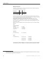
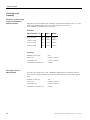
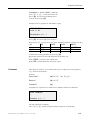
Precision and
Linearity
Precision and Linearity
of pH on Phosphate
Buffer Solution
Ampoules of precision pH buffer solutions, with values traceable to N.I.S.T., were
analyzed in random order in sets of 10 measurements on each of 6
AVL COMPACT pH/Blood Gas Analyzers.
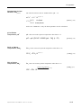
Precision
pH Value @ 37 °C
n
Mean
WRSD
6.841 ± 0.005
60
6.8409
0.0023
7.100 ± 0.005
60
7.0993
0.0025
7.383 ± 0.005
60
7.3823
0.0024
7.600 ± 0.005
60
7.5976
0.0019
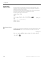
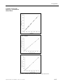
Linearity
Linearity of pH on
Whole Blood
20
Number of pairs (n):
240
slope (m):
0.9974 ± 0.0010
y-intercept (b):
0.0179 ± 0.0073
correlation coefficient (r):
1.0000
180 runs were made on two AVL COMPACT pH/Blood Gas Analyzers and on 1
AVL 995 after being tonometered to various concentrations of CO 2 and O 2 gas at
37°C.
Number of pairs (n):
180
slope (m):
0.9979 ± 0.0016
y-intercept (b):
0.0118 ± 0.0114
correlation coefficient (r):
0.9998
Operator’s Manual, AVL COMPACT 3, Rev. 2.0, June 1998
Method Sheet
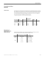
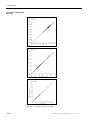
Precision and
Recovery on Whole
Blood
Whole blood was tonometered at 37°C to various levels of gravimetrically
prepared gases with CO 2 and O 2 concentrations certified to ± 0.03% absolute by
the manufacturer. Expected and observed values for P CO 2 and P O 2 were corrected
to 760 mmHg. For each tonometered level, 10 replicates were run on two AVL
COMPACT pH/Blood Gas Analyzers:
P CO 2
Analyte
type
n
Expected
Observed
S wr
% Recovery
1.00% CO 2
syringe
20
7.1
5.9
0.06
90
capillary
20
7.1
6.4
0.07
86
syringe
20
10.7
10.8
0.14
101
capillary
20
10.7
10.6
0.23
99
syringe
20
19.5
19.2
0.16
98
capillary
20
19.5
19.1
0.11
98
syringe
20
28.5
28.7
0.12
101
capillary
20
28.5
28.2
0.19
99
syringe
20
42.8
42.8
0.22
100
capillary
20
42.8
42.7
0.35
100
syringe
20
57.0
57.5
0.28
101
capillary
20
57.0
57.0
0.60
100
syringe
20
71.3
72.1
0.52
101
capillary
20
71.3
72.5
0.19
102
syringe
20
99.8
100.9
0.45
101
capillary
20
99.8
100.7
0.63
101
syringe
20
128.3
131.1
0.89
102
capillary
20
128.3
129.7
0.55
101
1.50% CO 2
2.97% CO 2
4.00% CO 2
6.00% CO 2
8.00% CO 2
10.00% CO 2
14.00% CO 2
18.00% CO 2
Linearity
Number of pairs (n):
180
slope (m):
1.0205 ± 0.0010
y-intercept (b):
-0.7408 ± 0.0637
correlation coefficient (r):
0.9999
Operator’s Manual, AVL COMPACT 3, Rev. 2.0, June 1998
21
Method Sheet
PO2
Analyte
type
n
Expected
Observed
S wr
% Recovery
2.93% O 2
syringe
20
20.9
20.9
0.30
100
capillary
20
20.9
20.8
0.43
99
syringe
20
28.5
28.3
0.37
99
capillary
20
28.5
28.0
0.23
98
syringe
20
57.0
56.6
0.44
99
capillary
20
57.0
56.7
0.39
99
syringe
20
99.6
99.1
0.58
99
capillary
20
99.6
99.6
0.46
100
syringe
20
114.1
113.9
0.58
100
capillary
20
114.1
115.2
0.84
101
syringe
20
142.6
144.2
1.16
101
capillary
20
142.6
140.8
1.56
99
syringe
20
213.9
213.2
0.72
100
capillary
20
213.9
210.8
2.62
99
syringe
20
356.5
352.6
2.13
99
capillary
20
356.5
350.4
2.73
98
syringe
20
570.4
565.3
5.97
99
capillary
20
570.4
562.9
2.82
99
4.00% O 2
8.00% O 2
13.97% O 2
16.00% O 2
20.00% O 2
30.00% O 2
50.00% O 2
80.00% O 2
Linearity
Number of pairs (n):
180
slope (m):
0.9872 ± 0.0008
y-intercept (b):
0.7362 ± 0.1920
correlation coefficient (r):
0.9999
All specific performance characteristics tests were run with default instrument
calibration and after normal recommended equipment quality control checks were
performed (see Operator’s Manual).
Specimens at each level were analyzed in replicates of two for 20 days. The
within-run and between-day standard deviations were calculated by the analysis of
variance method.
Model equation for regression statistics is: [results of AVL COMPACT 3
Analyzer] = slope(m) x [comparative method results] + intercept(b).
22
Operator’s Manual, AVL COMPACT 3, Rev. 2.0, June 1998
Method Sheet
Correlation to Other
Methods
Whole Blood
Specimens were collected for blood gas analysis by traditional operators of blood
gas equipment. The specimens were analyzed on existing instrumentation operated
and controlled by hospital procedures. If any specimen remained after the initial
run on the hospital system, the remainder was then run on the AVL COMPACT.
The results of the AVL COMPACT analysis follows:
Comparative Method: AVL 995, Blood Gas Analyzer
Correlation
Precision of
Measurement in
Whole Blood
Parameter Slope
Intercept
Coefficient
Range
n
pH
0.108
0.9920
6.96-7.63
141
0.9862
normalized to pH=7.4
0.006
P CO 2
0.9886
0.516
0.9967
18 - 90
141
PO2
0.9712
3.453
0.9976
1.7 - 376
141
Following is the summary of the expected performance specifications for the
Normal, Capillary, Mini sample and Micro sample modes.
Measuring Range (mmHg)
SD
pH
6.000-8.000
≤ 0.005
P CO 2
0-40
0-0.8 mmHg
40-200
0.8-3.0 mmHg
0-143
≤1.2 mmHg
143-742
1.2-15.0 mmHg
PO2
Operator’s Manual, AVL COMPACT 3, Rev. 2.0, June 1998
23
Method Sheet
Precision on Whole
Blood
The standard deviation for pH in whole blood is not easily specified, because the
pH value in-vitro can either be controlled or kept constant. The following data was
obtained through timed recording of the pH values, the curve was fitted with a
straight line and the mean deviation from this line was calculated.
pH Standard Deviation (1 S yx)
pH
6.000-8.000
0.005
For P CO 2 and P O 2 , whole blood was tonometered at 37°C to various levels of
gravimetrically prepared gases with CO 2 and O 2 concentrations. Five measurements
were obtained at each of 10 levels of gas and Mean and SD were calculated for each
of the four sample modes available on the AVL COMPACT pH/Blood Gas
Analyzer: Syringe, Capillary, Mini, and Micro Sample. Measurement was also
performed on the AVL OMNI Analyzer.
PCO 2 -Measurements
Syringe
Micro
Sample
x
1SD
x
1SD
x
TOTAL
x
1SD
x
17.8
18.1
0.23
18.0
0.27
17.8
0.45
17.9
0.27
18.0
0.32
20.6
20.9
0.34
20.9
0.26
20.9
0.28
20.6
0.35
20.8
0.31
27.5
28.1
0.37
28.2
0.23
27.6
0.26
27.8
0.25
27.9
0.28
27.5
27.9
0.38
28.0
0.55
27.7
0.46
27.7
0.42
27.8
0.46
37.7
38.2
1.07
38.0
0.78
38.7
0.35
38.3
0.18
38.3
0.69
41.2
42.07
0.35
41.8
0.58
41.6
0.88
41.8
0.43
41.8
0.59
67.8
37.6
1.55
68.6
0.55
68.8
0.58
69.7
0.57
68.7
0.92
68.8
70.5
0.60
70.4
0.42
69.7
1.05
70.7
0.73
70.3
0.73
103.1
102.9
0.76
103.5
0.90
104.0
1.54
104.0
1.68
103.6
1.28
139.5
139.5
1.64
140.0
1.99
137.6
2.80
140.8
4.17
139.5
2.82
Target
24
Capillary
Mini
Sample
1SD
1SD
Operator’s Manual, AVL COMPACT 3, Rev. 2.0, June 1998
Method Sheet
PO 2 -Measurements
Syringe
Mini
Sample
Capillary
Micro
Sample
TOTAL
x
1SD
x
1SD
x
1SD
x
1SD
x
1SD
0.0
1.07
0.47
0.89
0.47
0.83
0.36
0.70
0.57
0.87
0.47
21.0
20.9
0.53
21.1
1.50
20.7
0.60
20.6
1.05
20.8
1.00
44.7
44.4
1.00
44.4
1.12
43.3
0.64
43.3
1.68
43.8
0.93
76.0
67.6
1.55
68.6
0.55
68.8
0.58
69.7
0.57
68.7
0.92
96.2
95.7
0.70
96.7
0.96
97.5
0.88
97.1
1.10
96.7
0.92
135.6
137.3
3.25
136.3
1.24
137.4
1.38
137.8
1.14
137.2
1.95
300.7
290.8
3.60
295.1
1.87
294.12
8.18
293.7
3.06
293.4
4.81
344.0
336.9
6.65
342.1
4.07
343.6
3.48
343.6
9.93
341.5
6.55
501.2
492.1
11.11
489.1
7.19
486.7
8.39
494.3
9.30
490.5
9.11
659.5
640.1
12.61
647.7
11.80
644.6
12.22
641.6
20.55
643.5
14.75
Target
Operator’s Manual, AVL COMPACT 3, Rev. 2.0, June 1998
25
Method Sheet
Bibliography
1.
Teitz, Norbert W.,Ed.,Clinical Guide to Laboratory Tests, 2nd Ed., (Philadelphia: W.B. Saunders, Co., 1990).
2.
Shapiro BA, Harrison RA, Cane RD, Kozlowski-Templin R: Clinical Application of Blood Gases, 4th ed.,
(Chicago: Year Book Medical Publishers, Inc., 1991).
3.
Mahoney JJ, Wong RJ, Van Kessel AL: Reduced Bovine Hemoglobin Solution Evaluated for Use as a Blood
Gas Quality Control Material. Clin.Chem.1991; 39(5): 874-879.
4.
Mahoney JJ, et al. Changes in Oxygen Measurements when Whole Blood is Stored in Iced Plastic or Glass
Syringes, Clin.Chem. 1991; 37(7): 1244-1248.
5.
National Committee for Clinical Laboratory Standards. Blood Gas Pre-Analytical Considerations: Specimen
Collection, Calibration and Controls; Approved Guideline. NCCLS Document C27-A, (1993).
6.
National Committee for Clinical Laboratory Standards. Protection of Laboratory Workers from Infectious
Disease Transmitted by Blood, Body Fluids and Tissue - Second Edition; Tentative Guideline. NCCLS
Document M29-T2, (1992).
7.
National Committee for Clinical Laboratory Standards. Percutaneous Collection of Arterial Blood for
Laboratory Analysis - Second Edition; Approved Standard. NCCLS Document H11-A, (1992).
8.
National Committee for Clinical Laboratory Standards. Additives for Blood Collection Devices: Heparin;
Tentative Standard; NCCLS Document H24-T, (1988).
9.
National Committee for Clinical Laboratory Standards. Evaluation of Precision Performance of Clinical
Chemistry Devices - Second Edition; Tentative Guideline. NCCLS Document EP5-T2, (1992).
10. Snyder John R., Senhauser Donald A, (eds), Administration and Supervision in Laboratory Medicine, 2 nd ed,
(Philadelphia: J.B.Lippincott Co., 1989).
26
Operator’s Manual, AVL COMPACT 3, Rev. 2.0, June 1998
1 Introduction
1 INTRODUCTION
Analyzer Description..................................................................................................................... 1
Intended Use .............................................................................................................................. 1-1
Clinical Significance .................................................................................................................. 1-2
pH ........................................................................................................................................... 1-2
P CO 2 ....................................................................................................................................... 1-2
P O 2 ......................................................................................................................................... 1-2
Handling the Analyzer ............................................................................................................... 1-3
Location................................................................................................................................... 1-3
General Information ................................................................................................................. 1-3
Handling Blood and Blood Products .......................................................................................... 1-3
Hygienic Handling of Blood..................................................................................................... 1-3
Handling AVL Reagents............................................................................................................. 1-4
Precaution ................................................................................................................................ 1-4
Storage .................................................................................................................................... 1-4
Decontamination ........................................................................................................................ 1-5
Reagents .................................................................................................................................. 1-5
AVL Deproteinizer................................................................................................................ 1-5
Disinfectant .......................................................................................................................... 1-6
Fill port area ............................................................................................................................ 1-6
Sample drip tray.................................................................................................................... 1-6
Fill port ................................................................................................................................ 1-6
Flap ...................................................................................................................................... 1-7
Keyboard ................................................................................................................................. 1-7
Surfaces ................................................................................................................................... 1-7
Sample path / Measuring chamber ............................................................................................ 1-8
Handling the Electrodes ............................................................................................................. 1-8
Operator’s Manual, AVL COMPACT 3, Rev. 2.0, June 1998
1-I
1 Introduction
1 Introduction
Analyzer Description
Fig. 1-1: AVL COMPACT 3
• The AVL COMPACT 3 is an automatic microprocessor controlled pH /
Blood Gas Analyzer with an integral thermal printer.
• High safety, zero risk sample port and waste level control eliminate
contamination and infection hazard.
• A complete pH / Blood Gas analysis is performed on only 55 µ l of whole
blood with obvious benefits in neonatology, pediatrics and geriatrics.
• An optimized user interface reduces the requirement for extensive user
training.
• AVL zero-maintenance electrodes fit perfectly to the low maintenance
concept of the AVL COMPACT 3.
• Quick and precise analysis is completed within 20 seconds from sample
introduction to results.
• Lowest consumables and calibration gas requirement of any comparable
analyzer, ensures continued cost savings.
• Product design and AVL quality combine to ensure ultimate performance,
reliability and economy.
• Extensive self-diagnostic software, as featured on all AVL analyzers.
Intended Use
The AVL COMPACT 3 pH / Blood Gas Analyzer is intended to be used for the
measurement of pH, P CO 2 and P O 2 in samples of whole blood.
Operator’s Manual, AVL COMPACT 3, Rev. 2.0, June 1998
1-1
1 Introduction
Clinical Significance
pH
The pH-value of the blood, serum or plasma, may be the single most valuable
factor in the evaluation of the acid-base status of a patient. The pH-value is an
indicator of the balance between the buffer (blood), renal (kidney) and
respiratory (lung) systems, and one of the most tightly controlled parameters
in the body. The causes of abnormal blood pH-values are generally classified
as:
pH < 7.4
• primary bicarbonate deficit - metabolic acidosis
• primary hypoventilation - respiratory acidosis
pH > 7.4
• primary bicarbonate excess - metabolic alkalosis
• primary hyperventilation - respiratory alkalosis
An increase in blood, serum or plasma pH (alkalemia) may be due to increased
plasma bicarbonate, or a feature of respiratory alkalosis due to an increased
elimination of CO 2 due to hyperventilation.
A decreased pH-value (acidemia) in blood, serum or plasma may occur due to
an increased formation of organic acids, an increased excretion of H + -ions in
certain renal disorders, an increased acid intake such as in salicylate poisoning
or loss of alkaline body fluids. Respiratory acidosis is the result of a decreased
alveolar ventilation and may be acute; as the result of pulmonary edema,
airway obstruction or medication, or maybe be chronic; as the result of
obstructive or restrictive respiratory diseases.
PCO 2
The P CO 2 -value of arterial blood is used to assess how well the body
eliminates carbon dioxide in relation to the metabolic rate of CO 2 production.
A P CO 2 below the normal range is termed respiratory alkalosis and indicates
hypocapnia, a condition caused by increased alveolar ventilation such as
hyperventilation. An arterial P CO 2 above the normal range is termed
respiratory acidosis and indicates hypercapnia, a sign of hypoventilation and
failure, resulting from cardiac arrest, chronic obstructive lung disease, drug
overdose, or chronic metabolic acid-base disturbances.
PO 2
The P O 2 -value of arterial blood has become the primary tool for the evaluation
of arterial oxygenation status. Values below the normal arterial P O 2 (arterial
hypoxemia) are usually caused by pulmonary, circulatory, or respiratory
abnormalities (e.g. bronchial obstruction, vascular problems, decreased
cardiac output, increased oxygen demand, anatomical heart defect, low
inspired O 2 content). Generally, P O 2 -levels above 100 mmHg do not
contribute significantly to the oxygen content since, with normal hemoglobin
concentrations, 80 - 100 mmHg P O 2 provides a 97% saturation level, and a
level greater than 100% cannot be achieved.
1-2
Operator’s Manual, AVL COMPACT 3, Rev. 2.0, June 1998
1 Introduction
Handling the Analyzer
Location
For correct, trouble-free operation, the following environmental specifications
must be observed:
• Ambient temperature: +15 °C to + 32 °C (50 °F to 90 °F).
• Avoid direct sunlight.
• Avoid hazardous gases and vapors.
• Relative humidity: 20 - 90 %.
• Avoid locations beside strong electromagnetic fields (electric motors,
transformers, X-ray apparatus etc.). Avoid the use of cellular telephones
close to the device.
• Avoid vibration, use a solid surface.
• Allow sufficient space (at least 20 cm / 8 Inch minimum) around the
analyzer for air circulation and electrical supply.
General Information
The AVL COMPACT 3 should be switched on at all time. For switch-off
periods of more than 12 hours, the "shutdown procedure" described in
chapter 3 must be performed.
• Do not place liquids on top of the analyzer.
• Perform regular quality control tests (for further information, please refer
to chapter 5).
Handling Blood and Blood Products
Hygienic Handling
of Blood
Always handle blood with caution, as it may contain hazardous biological
substances.
WARNING: Waste liquids must be disposed of in accordance with local
regulations (biohazard).
Operator’s Manual, AVL COMPACT 3, Rev. 2.0, June 1998
1-3
1 Introduction
Handling AVL Reagents
NOTE:
AVL Medical Instruments cannot guarantee the performance of the
analyzer if any of the following situations occur:
• Reagents other than those recommended are used.
• Expiration dates of reagents have been exceeded.
• Reagents are not used according to AVL´s recommendations.
• The procedures described in this manual are not followed.
Precaution
AVL Deproteinizer contains sodium hypochlorite (≤ 2.0 % active chlorine).
Do not swallow the solution, avoid eyes and skin contact. In case of contact
wash the affected area with plenty of water. In case of eye contact consult a
physician as soon as possible.
Storage
Store AVL reagents in accordance with the information displayed on the
package label, allow reagents to stabilize at ambient temperature before use.
1-4
Operator's Manual, AVL COMPACT 3, Rev. 2.0, June 1998
1 Introduction
Decontamination
AVL recommends the following decontamination procedures. Decontamination
should be performed in accordance with typical laboratory regulations.
This decontamination should be performed periodically to minimize the risk of
infections (incl. hepatitis virus and HIV).
The purpose of this procedure is to minimize the risk when replacing items
that were in direct contact with blood.
NOTE: Always used approved, protective gloves!
The following parts of the device have to be decontaminated:
Daily
• Fill port area
• Keyboard
• Surfaces
As needed
• Sample path
Reagents
NOTE: Use liquid disinfectants only.
Do not use sprays!
AVL Deproteinizer
Composition
Aqueous solution of NaOCl containing ≤ 2.0 % active chlorine.
Hazards identification
Due to the basic and oxidizing character of the reagent ("Deproteinizer") local
irritations after contact with eyes, skin or mucous membranes cannot be
excluded.
First aid measures
After inhalation:
After skin contact:
After eye contact:
If swallowed:
fresh air, drink plenty of water
rinse with plenty of water, remove contaminated
clothes
rinse with plenty of water, consult a doctor
drink plenty of water, avoid vomiting, and consult a
doctor
NOTE: When Deproteinizer is handled and used properly, no ecological
problems are to be expected.
Operator's Manual, AVL COMPACT 3, Rev. 2.0, June 1998
1-5
1 Introduction
Disinfectant
A commercially available alcoholic disinfectant containing aldehyde should be
used (e.g.: Meliseptol). Please refer to the product description of the surface
disinfectant.
NOTE: Do not use the disinfectant for internal decontamination of the sample
path!
Fill port area
For decontamination AVL Deproteinizer is especially recommended.
You may also use a commercially available alcoholic disinfectant containing
aldehyde.
Sample drip tray
The sample drip tray prevents contamination of the bottle compartment (in
case of improper sample introduction). Decontaminate a dirty sample drip tray
with a cloth or gauze pad saturated in disinfectant.
Procedure
1.
2.
3.
4.
Fill port
Open bottle compartment cover.
Pull sample drip tray out.
Clean and decontaminate or replace it.
Close bottle compartment cover.
Decontaminate fill port with a cloth or gauze pad saturated in disinfectant.
Procedure
1.
Activate:
7UGTRTQITCOU!
oZm
5[UVGOVGUV!
o
'NGEVTQFGU!
o
2.
Open flap.
3.
Decontaminate fill port.
4.
5.
Close flap.
Press the key k twice upon completion of this maintenance procedure.
The system performs a washing/drying procedure and will return to the
"4'#&;" screen.
1-6
Operator’s Manual, AVL COMPACT 3, Rev. 2.0, June 1998
1 Introduction
Flap
Decontaminate the inside and outside of the flap with a cloth or gauze pad
saturated in disinfectant.
Procedure
1.
2.
3.
4.
5.
Activate:
7UGTRTQITCOU!
oZm
5[UVGOVGUV!
o
'NGEVTQFGU!
o
Open flap.
Decontaminate the inside and outside of the flap and wait until
disinfectant has dried.
Close flap only after disinfectant has dried completely to avoid damaging
the lacquer when reopening the flap.
Press the key k twice upon completion of this maintenance procedure.
The system performs a washing/drying procedure and will return to the
"4'#&;" screen.
Keyboard
Decontaminate the keyboard with a cloth or gauze pad saturated in
disinfectant.
NOTE: Decontaminate with damp cloth only using a disinfectant.
Do not use sprays!
Surfaces
Decontaminate all outside surfaces and cover with a cloth or gauze pad
saturated in disinfectant.
Operator’s Manual, AVL COMPACT 3, Rev. 2.0, June 1998
1-7
1 Introduction
Sample path /
Measuring chamber
Cleaning with AVL Deproteinizer should be performed only when the
measuring capillary is contaminated (protein residue) or if components of the
measuring path are being replaced.
Such cleaning process basically interferes with the measuring system and the
electrodes. They must be conditioned afterwards.
The decontamination agent is introduced via the fill port.
If necessary decontaminate the measuring chamber specially the connecting
pieces with a cloth saturated in disinfectant.
Procedure
Activate:
7UGTRTQITCOU!
oZm
/CKPVGPCPEG!
oZm
%NGCPKPI
o
!
Perform cleaning according instructions on the display.
NOTE:
After reinstalling of the decontaminated electrodes at a later time or
a new electrode perform two measurements with a wetting agent
(e.g. whole blood) to moisten the system.
Handling the Electrodes
Handle the electrodes with great care to prolong their operation life.
• Avoid contact between the electrode tip and hard surfaces.
• Never allow the electrodes to dry out, or store them unprotected.
For details, please refer to chapter 9, section "Care and Maintenance of
pH / Blood Gas Electrodes", and chapter 12, section "Care and Maintenance of
Remembranable pH / Blood Gas Electrodes".
1-8
Operator’s Manual, AVL COMPACT 3, Rev. 2.0, June 1998
2 Description of the Analyzer
2 DESCRIPTION OF THE ANALYZER
Main Features ............................................................................................................................ 2-1
Measurements .......................................................................................................................... 2-1
Calibration ............................................................................................................................... 2-1
Analyzer Components ................................................................................................................ 2-2
Display and Keys...................................................................................................................... 2-2
Thermal Printer ........................................................................................................................ 2-2
Cover ....................................................................................................................................... 2-3
Bottle Compartment.................................................................................................................. 2-3
Waste ................................................................................................................................... 2-4
Rinse .................................................................................................................................... 2-4
Buffer Type 1 (pH = 7.383) .................................................................................................. 2-4
Buffer Type 2 (pH = 6.841) .................................................................................................. 2-4
pH Reference Solution .......................................................................................................... 2-4
Cleaning Solution.................................................................................................................. 2-4
Sample Fill Module .................................................................................................................. 2-5
Flap ...................................................................................................................................... 2-5
Fill Port and Tube ................................................................................................................. 2-5
Sample Drip Tray.................................................................................................................. 2-5
Description of the Sample Path .................................................................................................. 2-6
Fill Port ................................................................................................................................ 2-6
Sample Inlet Path .................................................................................................................. 2-6
Measuring Capillary .............................................................................................................. 2-6
Measuring Chamber Valve ..................................................................................................... 2-6
Measuring Chamber Module ..................................................................................................... 2-7
Measuring Capillary .............................................................................................................. 2-7
Measuring Chamber Block..................................................................................................... 2-8
Measuring Chamber Valve ..................................................................................................... 2-8
Electrodes............................................................................................................................. 2-8
Peristaltic Pump ....................................................................................................................... 2-8
Rear Panel ............................................................................................................................... 2-9
Interfaces............................................................................................................................ 2-10
Gas Connections ................................................................................................................. 2-10
Power Switch Module.......................................................................................................... 2-11
Operator Interface ................................................................................................................... 2-12
Display .................................................................................................................................. 2-12
Keypad .................................................................................................................................. 2-12
Timeout .............................................................................................................................. 2-13
Operator’s Manual, AVL COMPACT 3, Rev. 2.0, June 1998
2-I
2 Description of the Analyzer
2 Description of the Analyzer
Main Features
The AVL COMPACT 3 is a fully automatic microprocessor-controlled
analyzer for quantitative "in-vitro" measurement of whole blood of the
following analytes:
pH
hydrogen ion activity
P CO 2 partial pressure of carbon dioxide
PO2
partial pressure of oxygen
BP
actual barometric pressure
Based on measured parameters, in conjunction with patient temperature, ctHb
and F IO 2 , the following parameters can be calculated:
BE
base excess
base excess of extra cellular fluid
BE ecf
base excess at actual oxygen saturation
BE act
BB
buffer base
actual bicarbonate
HCO 3 standard bicarbonate at a P CO 2 = 40 mmHg
cHCO 3 P CO 2 of 40 mmHg
ctCO 2
standard pH value at a P CO 2 of 40 mmHg
pH st
arterial-alveolar oxygen partial pressure difference
AaDO 2
hydrogen ion concentration
cH +
oxygen saturation
SO 2
oxygen content
ctO 2
Shunt
measurement for the direct mixture venous blood in the
oxygenated circulatory system
Measurements
The AVL COMPACT 3 analyzer is equipped with a sample detection system,
which identifies air bubbles in a sample, controls the positioning of a sample
in the instrument, and determines the volume of a sample. With a blood sample
volume of at least 55 µ l in place, an automatic Blood Gas measurement is
performed.
With a blood sample volume of > 25 to 55 µ l (Microsampler) a semi-automatic
measurement of pH, P CO 2 and P O 2 will be performed.
Calibration
The following calibrations are initiated and performed automatically:
•
•
Main calibration
pH 1P calibration
The following calibrations are operator-initiated calibrations and will be
performed automatically:
•
•
pH 2P calibration
Gas 2P calibrations
For details, please refer to chapter 6, "Calibrations".
Operator’s Manual, AVL COMPACT 3, Rev. 2.0, June 1998
2-1
2 Description of the Analyzer
Analyzer Components
Display and Keys
Display
Keys
numeric keypad
Fig. 2-1: Display
Measured results, calculated parameters, and diagnostic informations appear
on a four-line alphanumeric LCD display.
The keys and the numeric keypad in conjunction with the display provide
control of all analyzer functions:
• measurements
• data input
• programming
• maintenance
• system test
Thermal Printer
Fig. 2-2: Thermal printer
The analyzer is equipped with a 24-column thermal printer using special
(58 mm) wide paper with one heat-sensitive surface.
The following data can be printed out:
• measured values
• calculated values
• calibration data
• electrode voltage
• system messages
2-2
Operator’s Manual, AVL COMPACT 3, Rev. 2.0, June 1998
2 Description of the Analyzer
Cover
It is essential to ensure the cover of the analyzer is closed during
measurements and calibrations to prevent electrical interference and maintain
temperature stability of the measuring system.
The cover can be held in an open position using the door rod to secure the
door.
Fig. 2-3: View with open top cover
Bottle Compartment
In the bottle compartment the following reagents / containers are required
•
•
•
•
•
•
Waste
Rinse
Buffer Type 1
Buffer Type 2
pH Reference Solution
Cleaning Solution
Cleaning Solution
Buffer Type 2
Fig. 2-4: Reagents
NOTE: The ambient temperature for storing all reagents ranges from
5 °C to 30 °C (41 °F to 86 °F).
Operator’s Manual, AVL COMPACT 3, Rev. 2.0, June 1998
2-3
2 Description of the Analyzer
Waste
All liquids used by the analyzer are collected in the Waste container.
CAUTION: A trouble-free wash and dry cycle can be ensured only if the
system is completely sealed. The Waste container lid must be
tightly closed.
Rinse
Buffer Type 1
(pH = 7.383)
Buffer Type 2
(pH = 6.841)
The Rinse is used:
• to wash out the sample;
• to wash out the calibration solution.
The Buffer Type 1 is used to determine the first point of a pH calibration.
The bottle is placed behind the Buffer Type 1 bottle inside the bottle
compartment.
The Buffer Type 2 solution is used to determine the second point of a pH
calibration.
pH Reference Solution
This solution is pumped into the pH-reference electrode by means of a KCl
pressure circulation system and the sample.
The pH Reference Solution is transported only if the bottle cap is closed
tightly.
Cleaning Solution
The bottle is placed behind the pH Reference Solution inside the bottle
compartment.
A cleaning cycle is automatically performed after 50 samples during the next
main calibration.
CAUTION:
2-4
Do not mix or refill reagents.
Use only AVL reagents.
Operator’s Manual, AVL COMPACT 3, Rev. 2.0, June 1998
2 Description of the Analyzer
Sample Fill Module
This module consists of the following parts:
• Flap
• Fill port and tube
• Sample drip tray
Flap
Fill port
Sample drip tray
Fig. 2-5: Sample fill module
Flap
The flap has to be opened for a sample input.
CAUTION: If the flap is opened by mistake, the running action will be
interrupted. The analyzer prompts the operator to close the flap
and a wash/dry cycle will be performed.
Fill Port and Tube
The fill port (see Fig. 2-5) allows samples to be injected or aspirated from
• syringes,
• AVL Microsampler and
• capillaries without the need of adapters.
Sample Drip Tray
The sample drip tray is placed on the lower end of the fill module to avoid
sample spilling. The tray is replaced as part of the scheduled maintenance
procedures or when it becomes very soiled.
Operator’s Manual, AVL COMPACT 3, Rev. 2.0, June 1998
2-5
2 Description of the Analyzer
Description of the Sample Path
Fill Port
The sample is injected or aspirated into the fill port of the
AVL COMPACT 3 using a syringe, capillary or AVL Microsampler.
The fill port is made of soft PVC and serves as an interface between the
sample container and the sample path. The fill port is designed so those
samples can be injected or aspirated via syringe, capillary or Microsampler
without the need of an adapter.
The sample flows through the preheating tube.
Sample Inlet Path
The metal sample inlet path heats the sample up to 37° C.
The sample inlet path is also the first contact for sample detection and the first
contact path (K 0 - Mini Sample).
Measuring Capillary
The analyzer aspirates the sample from the sample inlet path into the
measuring capillary.
In the measuring capillary, the sample contacts the electrodes. Before the
sample reaches the measuring chamber valve it passes the second electrical
contact for sample detection. In the measuring capillary, an electrical contact
for sample detection is positioned between the P O 2 and P CO 2 Electrode.
The AVL COMPACT 3 detects the sample and controls the filling of the
measuring capillary by means of contact paths.
After the pH blood gas measurement is completed, the sample is moved into
the waste bottle.
Measuring Chamber
Valve
2-6
The electromagnetic measuring chamber valve closes the measuring chamber
and avoids the direct filling of a syringe sample into the measuring chamber.
The sample is pushed into a bypass tube. This construction ensures a
continuous and bubble-free filling of the measuring chamber. It also prevents
electrode damage from excessive pressure.
Operator’s Manual, AVL COMPACT 3, Rev. 2.0, June 1998
2 Description of the Analyzer
Measuring Chamber
Module
The measuring chamber module consists of the following parts:
D
C
A
B
Fig. 2-6: Measuring chamber module
A measuring capillary
B measuring chamber block
C measuring chamber valve
D electrodes
Measuring Capillary
Fig. 2-7: Measuring capillary
In the measuring capillary the Blood Gas Electrodes and the pH Electrode are
in direct contact with the sample to measure the Blood Gas parameters and the
pH-value.
The measuring capillary is permanently illuminated so that the entire
aspiration cycle can be observed.
Operator’s Manual, AVL COMPACT 3, Rev. 2.0, June 1998
2-7
2 Description of the Analyzer
Measuring Chamber
Block
Measuring Chamber
Valve
Electrodes
The entire module is thermostated at 37 °C.
The measuring chamber solenoid valve is located at the right end of the
measuring chamber block.
This valve prevents direct access from the pre-induction tube (i.e. syringe
injection) to the measuring chamber module to avoid damage of the electrodes.
The electrodes are inserted into the measuring chamber block from the rear.
The electrode tips project into the measuring capillary thus
come into contact with the sample material.
The electrodes are color-coded for easy identification.
Listed from left to right:
white
gray
green
blue
pH Reference
pH
P CO 2
PO2
Fig. 2-8: Electrodes
Peristaltic Pump
The peristaltic pump is used to transport all samples and liquids inside the
analyzer.
Fig. 2-9: Peristaltic pump
2-8
Operator’s Manual, AVL COMPACT 3, Rev. 2.0, June 1998
2 Description of the Analyzer
Rear Panel
Warning and identification plates with model and serial numbers are located
on the rear panel of the unit.
NOTE: Only a trained service engineer is authorized to open the rear panel.
Fig. 2-10: Rear panel
Fig. 2-11: W arning and identification plates
Operator’s Manual, AVL COMPACT 3, Rev. 2.0, June 1998
2-9
2 Description of the Analyzer
Interfaces
COM 3: 25-pin (female)
COM 2: 9-pin (female)
COM 1: 9-pin (female)
Fig. 2-12: Interface
The standard bi-directional interface (RS232 C, Submin. D-connector) enables
the user to connect the analyzer with a Host Computer, an external printer or
ticket printer.
In addition, the unit is provided with an interface option for a Bar code
scanner and for data link with an AVL Oximeter or an AVL Electrolyte
Analyzer and / or with an external service modem.
Gas Connections
Gas 2 (10 % CO2, balanced N2)
Gas 1 (5.5 % CO2, 20 % O2, balanced N2)
Fig. 2-13: Gas connections
Connections for gas tubing are located in the lower right corner of the rear
panel.
2-10
Operator’s Manual, AVL COMPACT 3, Rev. 2.0, June 1998
2 Description of the Analyzer
Power Switch Module
Fig. 2-14: Power switch module
This module consists of a power switch, power input, fuses, and a power line
filter.
Operator’s Manual, AVL COMPACT 3, Rev. 2.0, June 1998
2-11
2 Description of the Analyzer
Operator Interface
Display
The display helps you to operate the analyzer.
When the unit is ready for measurement, the display reads as follows:
4'#&;
(QTOGCUWTGOGPV
QRGPVJGHNCR
7UGTRTQITCOU!
First line:
current status of the analyzer, actual time.
Second and third line: display instructions, alarms and measuring values.
Fourth line:
indicates user programs and questions; selection,
activation and data input.
Keypad
The keypad in conjunction with the display provides control of all analyzer
functions
Keys
Function
Data input
o
• activates user programs
• answers indicated questions
• confirms indicated values
n
• negates indicated questions
m
• selects next function
• negates indicated questions
• input of time/date
l
• selects previous function
• input time/date
k
• confirms / completes data
input
• interrupts the program sequence • aborts data input
• interrupts all actions
• exits user programs
• jumps to previous menu
EXCEPT: calibrations and measurements: an interruption by
pressing k must be confirmed by pressing o .
• input of all numerical values
Except: time / date
• input of signs
• at each key touch the cursor
will be placed back for one
digit, without deleting other
digits
EXCEPT: patient number
2-12
Operator’s Manual, AVL COMPACT 3, Rev. 2.0, June 1998
2 Description of the Analyzer
Timeout
If no key was pressed, the analyzer automatically returns within 30 sec from
each user program to 4'#&;.
Exception: the user program "System Test".
Operator’s Manual, AVL COMPACT 3, Rev. 2.0, June 1998
2-13
2 Description of the Analyzer
2-14
Operator’s Manual, AVL COMPACT 3, Rev. 2.0, June 1998
3 Installation, Shutdown
3 INSTALLATION / SHUTDOWN
Installation ................................................................................................................................. 3-1
Location................................................................................................................................... 3-2
Solenoid Valve Relief Clamps................................................................................................... 3-2
Peristaltic Pump Tube............................................................................................................... 3-3
Filling and Connecting the Bottles ............................................................................................ 3-4
Waste Bottle ......................................................................................................................... 3-4
Rinse, pH Reference Solution, Buffer Type 1, Buffer Type 2, Cleaning Solution..................... 3-4
Calibration Gas Connection ...................................................................................................... 3-5
Electrodes ................................................................................................................................ 3-6
pH Reference Electrode (white) ............................................................................................. 3-6
Inserting Printer Paper ............................................................................................................ 3-10
Shutdown ................................................................................................................................. 3-11
Longer than 3 Days................................................................................................................. 3-11
Rinse and Dry the Tubes...................................................................................................... 3-11
Electrode Care .................................................................................................................... 3-12
Releasing the Peristaltic Pump Tube .................................................................................... 3-13
Releasing the Tubes ............................................................................................................ 3-13
Storage, Transportation ....................................................................................................... 3-14
Operator’s Manual, AVL COMPACT 3, Rev. 2.0, June 1998
3-I
3 Installation, Shutdown
3 Installation / Shutdown
This chapter describes the installation and shutdown procedures.
Installation
After the AVL COMPACT 3 has been unpacked and placed in a location
according to the requirements described in chapter 1, the following steps
should be performed:
Check whether analyzer and accessories are complete and undamaged. Check
contents against the supplied packing list.
If parts are missing inform your AVL representative. In case of damage inform
your carrier immediately. Keep analyzer and packing material until any queries
have been addressed.
NOTE: Packing may vary by country and slight variation from the accessories
list.
Contact your AVL representative for your specific list.
Description
1
1
1
1
2
1
1
1
1
set
pcs.
pcs.
pcs.
pcs.
pcs.
pcs.
pcs.
pcs.
1 pcs.
1 pcs.
dummy electrodes (four pieces)
lamp 28 V
80 mAT / 250 V (F1/F2)
1.6 AT / 250 V (F3 / mains fuse)
3.2 AT / 250 V (F4)
nozzle cleaning needle
tubing set for peristaltic pump
fill port
quad ring seal for pH Reference Solution bottle
(28.17 x 3.53 mm)
quad ring seal for measuring chamber
(1.06 x 1.25 mm)
quad ring seal for waste (50.4 x 3.53 mm)
leak proof adapter (measuring chamber valve)
1 pcs.
power cable (∅ = 1.5 mm 2 ; length = approx. 2 m)
1 pcs.
1 pcs.
sample drip tray
operator’s manual
1 pcs.
Operator’s Manual, AVL COMPACT 3, Rev. 2.0, June 1998
3-1
3 Installation, Shutdown
Location
Solenoid Valve
Relief Clamps
For correct, trouble-free operation, the following environmental specifications
must be observed:
• Ambient temperature: +15 °C to + 32 °C (50 °F to 90 °F).
• Avoid direct sunlight.
• Avoid hazardous gases and vapors.
• Relative humidity: 20 - 90 %.
• Avoid locations beside strong electromagnetic fields (electric motors,
transformers, X-ray apparatus etc.). Avoid the use of cellular telephones
near the device.
• Avoid vibrations, use a solid surface.
• Allow sufficient space (at least 20 cm / 8 Inch minimum) around the
analyzer for air circulation and electrical supply.
In the AVL COMPACT 3 analyzer, relief clamps are inserted under the
solenoid valves to prevent tube damage.
Before installing the analyzer remove the relief clamps and reinsert it during
shutdown procedure.
NOTE: Do not forget to remove the relief clamps, otherwise no proper start
up operation will occur.
The clamps designed for this purpose can easily be removed by lifting
the solenoid fixtures.
Slightly pull the armature of the valves when removing the relief
clamps. Take care for the solenoid valve relief clamps, you will need it
for a possible later shutdown.
Open the cover of the analyzer to gain access to the solenoid valves relief
clamps.
Six of them (V3, V4, V5, V7, V11, V12) are located to the right of the
measuring chamber (see Fig. 3-1), one to the right of the peristaltic pump (see
Fig. 3-2).
Open the bottle compartment cover (transparent gray plastic) and remove the
three solenoid valve red relief clamps from the solenoid valves (V6, V8, V10)
in the bottle compartment (see Fig. 3-3).
Fig. 3-1: Solenoid valve relief clamps - fill module
3-2
Operator’s Manual, AVL COMPACT 3, Rev. 2.0, June 1998
3 Installation, Shutdown
Fig. 3-2: Solenoid valve relief clamps - peristaltic pump
Fig. 3-3: Solenoid valve relief clamps - bottle compartment
Peristaltic Pump
Tube
Fig. 3-4: Peristaltic pump tubes
Procedure
• Push end of tension lever to the right and slightly against the pump plate
until it locks with a click.
Operator’s Manual, AVL COMPACT 3, Rev. 2.0, June 1998
3-3
3 Installation, Shutdown
Filling and
Connecting the
Bottles
Located under the measuring chamber and the fill module, the reagent
compartment houses the fluid containers.
The screw-on caps with tubing for the containers are connected to the liquid
circulation system which projects from the rear wall of the reagent
compartment.
NOTE: Ensure to place the caps to the corresponding reagent bottles and pay
attention, that no tube is folded.
Waste Bottle
Before screwing the cap on the Waste bottle, ensure that the ring seal is
properly in place.
If the seal is in place, screw the cap onto the empty Waste container and insert
the bottle into its socket in the bottle compartment.
NOTE: Ensure that the Waste bottle is completely airtight to allow a
trouble-free operation.
Rinse, pH Reference
Solution, Buffer Type 1,
Buffer Type 2,
Cleaning Solution
The necks of the bottles are sealed with aluminum foil.
Remove the foil by cutting along the edge of the bottleneck.
NOTE: When removing the foil, make sure that the fluids are not
contaminated.
NOTE: If you do not use the Rinse reagent, fill the bottle with distilled water
and add one ampoule of Rinse Additive.
Screw the caps on the bottles and place them in their sockets in the bottle
compartment.
NOTE: Before screwing on the cap of the pH Reference Solution bottle,
ensure that the ring seal is properly in place.
Ensure that the cap is screwed on finger tight otherwise the
pH Reference Electrode will not function properly.
After installing the pH Reference Solution, do not switch on the
analyzer before a pH Reference Electrode has been installed!
3-4
Operator’s Manual, AVL COMPACT 3, Rev. 2.0, June 1998
3 Installation, Shutdown
Calibration Gas
Connection
The AVL COMPACT 3 needs two different calibration gases.
Gas 2 (10 % CO2, balanced N2)
Gas 1 (5.5 % CO2, 20 % O2, balanced N2
Fig. 3-5: Gas connection
Fig. 3-6: Position of calibration gas cylinder
Procedure
•
•
•
•
Install the pressure regulators on the new gas cylinders.
Insert the new cylinders in the holder and secure them.
Connect the tubes to the outlet of the gas reduction valve.
Connect the tubes to the connector nipples on the rear panel of the
AVL COMPACT 3.
• Open the valves of the gas cylinders again.
NOTE: Do not mix up bottles and tubes.
NOTE: The length of the gas tube is limited at 1m (3 ft). Avoid large distances
between analyzer and gas cylinder.
Please contact your AVL customer support if larger distances are
necessary.
Operator’s Manual, AVL COMPACT 3, Rev. 2.0, June 1998
3-5
3 Installation, Shutdown
Electrodes
NOTE: Zero maintenance pH / Blood Gas Electrodes do not require any
preparation.
Fig. 3-7: Removal of transport housing
Before installing the remembranable electrodes remove transport housing
(twist (1) and pull (2) ) and fit them with a new electrode housing (see
chapter 12, "Care and Maintenance of Remembranable pH / Blood Gas
Electrodes ").
NOTE: Save transport housing for possible storage or transport.
The electrodes do not require cleaning with electrode paste at this stage.
Install the electrodes from right to left in the following sequence:
• P O 2 Electrode (blue)
• P CO 2 Electrode (green)
• pH Electrode (gray)
Pull out the electrode clips and insert the electrodes into the measuring
chamber block.
Secure the electrodes with the clips and connect the electrode cables.
pH-Reference Electrode
(white)
1. Carefully remove the protective caps from the pH Reference Electrode
nipples. Connect the unmarked tube to the lower nipple and the yellowcoded tube to the yellow-coded upper nipple.
Yellow marking
Fig. 3-8: pH Reference Electrode - yellow marking
3-6
Operator’s Manual, AVL COMPACT 3, Rev. 2.0, June 1998
3 Installation, Shutdown
Replace the pH Reference Electrode housing with a new one.
Fill the pH Reference Electrode with pH Reference Solution, before
inserting into the measuring chamber block.
2. Plug the power cord into an electrical outlet and switch on the analyzer.
3. The following display appears:
%1/2#%6
2NGCUGYCKV
When the correct temperature is reached, the following display with the
correct temperature appears.
9#4/72
/%VGOR
52VGOR
%
%
During the warm up there is a conditioning of the P O 2 - and P CO 2 electrode.
9#4/72
2NGCUGYCKV
4. Check the automatic filling function of the pH Reference Electrode housing
(see chapter 9).
If the pH Reference Electrode is filled, continue with item 5.
Operator’s Manual, AVL COMPACT 3, Rev. 2.0, June 1998
3-7
3 Installation, Shutdown
If the pH Reference Electrode was not filled:
Take pH Reference Electrode out of the measuring chamber.
NOTE: Do NOT disconnect cable and tubes!
Activate:
/CKPVGPCPEG!
oZm
4GHg'NGEVTQFG!
o
75'4241)4#/5
4GHgGNGEVTQFG
(KNNGNGEVTQFG!
Press o .
This function activates the automatic filling of the pH Reference Electrode
housing.
On completion of the filling procedure, the following display appears:
75'4241)4#/5
4GHgGNGEVTQFG
(KNNGNGEVTQFG!
5. Press n when the electrode is filled.
The permeability of the pH Reference Electrode diaphragm should be
tested.
Carefully touch the electrode tip with a clean dry tissue.
75'4241)4#/5
4GHgGNGEVTQFG
%JGEMRGTOGCDKNKV[!
Press o to confirm.
Observe the electrode tip for the formation of a small droplet of pH
Reference Solution.
75'4241)4#/5
4GHgGNGEVTQFG
%JGEMRGTOGCDKNKV[!
3-8
Operator’s Manual, AVL COMPACT 3, Rev. 2.0, June 1998
3 Installation, Shutdown
If no droplet has formed on the tip, press o to confirm and repeat this
procedure, otherwise exit this program by pressing k .
If again no droplet has formed replace the pH Reference Electrode housing
in accordance with the instructions given in chapter 9, "Maintenance".
Fig. 3-9: pH Reference Electrode - droplet
If the droplet has formed, wipe it off carefully, insert the electrode into the
measuring chamber and secure with the clip.
Press k to exit the program.
Operator’s Manual, AVL COMPACT 3, Rev. 2.0, June 1998
3-9
3 Installation, Shutdown
Inserting Printer
Paper
1.
2.
3.
4.
Push the paper roll holder slightly to the side
Put a new roll of paper into the mounting support.
Insert the paper in the feeder.
Press the paper feed (black) button until the paper appears at the outside of
the cover.
4
3
1/2
Fig. 3-10: Paper insertion
NOTE: The paper is heat-sensitive on one side only. Make sure that it is
inserted correctly.
3-10
Operator’s Manual, AVL COMPACT 3, Rev. 2.0, June 1998
3 Installation, Shutdown
Shutdown
If the AVL COMPACT 3 is to be put out of use for a longer period of time, it
is possible to activate the economy standby mode. During this time, the
analyzer does not need Buffer Type 1 or Buffer Type 2, but the electrodes
have the optimal conditioning.
If necessary, a "Manual Standby" or "Automatic Standby" can be activated.
For details, see chapter 8 "Settings" section " Manual Standby" or "Automatic
Standby".
This economy standby mode can be canceled at any time. After performing the
necessary calibration the analyzer is 4'#&;.
Longer than 3 Days
If your AVL COMPACT 3 is to be shut down completely for more than 3 days,
you have to empty the tubes, remove the electrodes from the measuring
chamber and secure some of the tube valves with the relief clamps.
Procedure
4'#&;
(QTOGCUWTGOGPV
QRGPVJGHNCR
7UGTRTQITCOU!
Rinse and Dry the
Tubes
1. Take both tubes off the pH Reference Electrode and connect them with
each other by means of a nipple. Close the two nipples of the pH Reference
Electrode with the two supplied red stoppers.
NOTE: A capillary tube may also be used instead of a nipple.
Do not insert the ends of the capillary into the tubes deeper than
10 mm.
2. Empty Buffer Type 1, Buffer Type 2, pH Reference Solution and Cleaning
Solution, rinse them, fill them with distilled water and put them back into
the analyzer.
3. Activate:
7UGTRTQITCOU!
oZm
/CKPVGPCPEG!
oZm
5JWVFQYP!
o
75'4241)4#/5
5JWVFQYP
4KPUG!
Operator’s Manual, AVL COMPACT 3, Rev. 2.0, June 1998
3-11
3 Installation, Shutdown
Press o.
A rinsing cycle is now activated during which the entire reagent inlet and
outlet tubing system is rinsed.
Empty the bottles of Buffer Type 1, Buffer Type 2, pH Reference Solution,
Cleaning Solution and Rinse.
75'4241)4#/5
5JWVFQYP
&T[!
Press o.
75'4241)4#/5
5JWVFQYP
&T[CEVKXCVGF
The liquids are aspirated and the tubing system is dried.
75'4241)4#/5
5JWVFQYP
5YKVEJQHHCPCN[\GT
4.
5.
6.
7.
Electrode Care
Switch off the power supply.
Close the valve of the calibration gas cylinders.
Insert the solenoid valve relief clamps.
Empty, decontaminate and dry the waste bottle and put it back into the
analyzer.
Disconnect the electrode cables and lift the electrode clips.
The electrodes may now be removed.
NOTE: Reinsert the electrode clips to avoid losing them.
Storage for only one day
To prevent the electrodes from drying out fill the protective caps with:
• pH Electrode:
Buffer Type 1
• P CO 2 Electrode:
P CO 2 /TCO 2 Filling Solution
• P O 2 Electrode:
do not fill
• pH Reference Electrode:
pH Reference Solution
and seal them with Parafilm® .
3-12
Operator’s Manual, AVL COMPACT 3, Rev. 2.0, June 1998
3 Installation, Shutdown
Transport (only for Remembranable Electrodes)
• Remove the electrode housing from the corresponding electrode.
• Fill the transport housing with the corresponding electrolyte (Exception:
P O 2 Electrode):
• Remove the outside O-ring from the transport housing for opening the
discharge pore
Fig. 3-11: Transport housing
• Fit the electrodes with the filled transport housing
Releasing the Peristaltic
Pump Tube
Releasing the Tubes
Unlock tension lever. Push on hook-shaped until tension lever moves left and
pump tube tension is released.
To prevent tube damage in the AVL COMPACT 3 analyzer during transport,
relief clamps are inserted under the solenoid valves to.
NOTE: The clamps designed for this purpose can easily be removed by lifting
the solenoid fixtures.
Six of them (V3, V4, V5, V7, V11, V12) are inserted to the right of the
measuring chamber (see Fig. 3-12), one to the right of the peristaltic pump
(see Fig. 3-13).
The remaining three red solenoid valve relief clamps have to be inserted (V6,
V8, V10) in the bottle compartment (see Fig. 3-14).
Fig. 3-12: Solenoid valve relief clamps - fill module
Operator’s Manual, AVL COMPACT 3, Rev. 2.0, June 1998
3-13
3 Installation, Shutdown
Fig. 3-13: Solenoid valve relief clamps - peristaltic pump
Fig. 3-14: Solenoid valve relief clamps - bottle compartment
Storage, Transportation
3-14
Protect the AVL COMPACT 3 with a dust cover during storage.
For transportation purposes use the original shaped parts packing material.
Operator’s Manual, AVL COMPACT 3, Rev. 2.0, June 1998
4 Patient Testing
4 PATIENT TESTING
Sample Preparation.................................................................................................................... 4-1
Important when Storing Blood .................................................................................................. 4-1
Sample Measurement ................................................................................................................. 4-2
Syringe Measurement ............................................................................................................... 4-2
Capillary or Microsampler Measurement ................................................................................... 4-4
Micro sample ........................................................................................................................... 4-6
Printout of Results.................................................................................................................... 4-9
Password Option ...................................................................................................................... 4-10
Password - OFF ...................................................................................................................... 4-10
Password - ON (Measurement - ON)........................................................................................ 4-10
Password - ON (Measurement - OFF) ...................................................................................... 4-11
Parameter and Data Input ....................................................................................................... 4-12
Parameter Input ...................................................................................................................... 4-12
Modification of Patient’s Temperature.................................................................................. 4-13
Modification of tHb Value ................................................................................................... 4-14
Modification of tHb Type for Fetal and Adult Blood............................................................. 4-14
Modification of Fraction of Inspired Oxygen ( F IO 2 ) ............................................................. 4-14
Modification of Respiratory Quotient (RQ) .......................................................................... 4-15
Modification of Half- Saturation Pressure ............................................................................ 4-15
Modification of Sample Type............................................................................................... 4-16
Input of Patient- Related Data ................................................................................................. 4-17
Entering Patient’s Number (Manual)..................................................................................... 4-18
Entering Patient’s Number (Barcode) ................................................................................... 4-18
Entering Patient’s Sex.......................................................................................................... 4-18
Entering Patient’s Age ......................................................................................................... 4-18
Printout.................................................................................................................................... 4-19
Measurement Reports ............................................................................................................. 4-20
Data Input........................................................................................................................... 4-20
Reports ............................................................................................................................... 4-20
Calibration Reports ................................................................................................................ 4-21
Error Report........................................................................................................................... 4-21
System Status ......................................................................................................................... 4-22
Operator’s Manual, AVL COMPACT 3, Rev. 2.0, June 1998
4-I
4 Patient Testing
4 Patient Testing
This chapter describes routines used to operate of AVL COMPACT 3.
Sample Preparation
NOTE: Always observe the laboratory regulations, when collecting blood.
For capillary blood samples, it is advisable to use AVL capillary tubes, which
contain a special Heparin coating.
The most advanced and user-friendly device for collecting arterial blood is the
AVL Microsampler.
Fig. 4-1: AVL Microsampler
The use of very thin needles prevents common complications such as
hematoma, thrombosis etc. which may occur after an arterial puncture.
NOTE: When the Microsampler needle punctures an artery, a pulsating blood
flow filling of the capillary tube can be observed.
Continuous flow indicates that a vein has been punctured.
Important when
Storing Blood
CAUTION: The higher the temperature of a sample, the faster and more
intensive its metabolism (means change of Blood Gas and pH
values).
The ideal temperature for long-term storing of blood is approx. 4° C
(39 °F).
At this temperature the metabolism of a sample and, as a consequence, its
oxygen consumption are lowest.
At a temperature of 4° C, a sample may be kept for up to two hours without
significant changes of its Blood Gas and pH values.
When using an AVL Microsampler, the sample does not require icing for up to
30 min.
For details, please refer to chapter 13!
Operator’s Manual, AVL COMPACT 3, Rev. 2.0, June 1998
4-1
4 Patient Testing
Sample Measurement
Syringe
Measurement
Before a measurement can be performed, the analyzer must be in 4'#&;
mode.
4'#&;
(QTOGCUWTGOGPV
QRGPVJGHNCR
7UGTRTQITCOU!
NOTE: Before measurement, turn the syringe in your hand for about 10
seconds to mix the sample and remove any air by injecting it onto a
cotton swab.
Open the flap.
/'#574'/'06
+PLGEVUCORNGQT
UGNGEVCURKTCVKQP
#URKTCVKQP!
Insert the syringe into the fill port and inject the sample s l o w l y .
Fig. 4-2: Syringe measurement
As soon as the requisite sample volume is injected, an acoustic signal will
sound and the following display appears:
/'#574'/'06
4GOQXGU[TKPIG
ENQUGVJGHNCR
Remove the syringe from the fill port and close the flap.
4-2
Operator’s Manual, AVL COMPACT 3, Rev. 2.0, June 1998
4 Patient Testing
NOTE: If the flap is opened again while the sample is being aspirated and not
closed before the countdown reaches 000, a continuous beep will
sound until the flap is closed.
If the flap is opened during the measurement, the measurement will be
aborted.
NOTE: Do not open the cover during measurements!
/'#574'/'06
'FKVRCVKGPVFCVC!
The analyzer performs a fully automatic measurement.
The transparent, illuminated measuring channel enables the user to observe the
movement of a sample and to identify blockages or air bubbles. During
measurement, data input (input patient or sample related data) is possible.
If a barcode scanner is installed, it is possible to scan in the patient number
during measurement (from sample stop up to reaching 4'#&;) as well as
during the function "Data input" - "Patient number".
Please refer to chapter 8 "Settings", section "Interfaces" for further
information.
The countdown running in the upper right corner of the display during the
measurement ends with the display of measured pH, P CO 2 and P O 2 and one of
the calculated values (for details, please refer to chapter 8, section "Settings" "Display") and printout of the results.
%10&+6+10+0)
R*g2%1g
21g$'g
'FKVRCVKGPVFCVC!
On completion of the measurement, the results are displayed and printed out,
and a gas conditioning is started. As soon as the countdown reaches 20
seconds, an asterisk (*020) appears to indicate that the flap can now be opened
for further measurement (max. 4 times) before the end of the conditioning
cycle is reached.
If the flap is not opened before completion of the countdown, the analyzer
returns to 4GCF[ and the display will read as follows:
4'#&;
(QTOGCUWTGOGPV
QRGPVJGHNCR
7UGTRTQITCOU!
Operator’s Manual, AVL COMPACT 3, Rev. 2.0, June 1998
4-3
4 Patient Testing
Capillary or
Microsampler
Measurement
Before a measurement can be performed, the analyzer must be in the 4'#&;
mode.
Fig. 4-3: Capillary measurement
4'#&;
(QTOGCUWTGOGPV
QRGPVJGHNCR
7UGTRTQITCOU!
Open the flap.
/'#574'/'06
+PLGEVUCORNGQT
UGNGEVCURKTCVKQP
#URKTCVKQP!
Press owhen "#URKTCVKQP!" is indicated.
Carefully insert the capillary into the fill port.
NOTE: At least 55µ l sample volume is required!
If under "Settings" the function "Mini sample" was activated, the following
display appears:
/'#574'/'06
5CORNG
KUCURKTCVGF
/KPKUCORNG!
4-4
Operator’s Manual, AVL COMPACT 3, Rev. 2.0, June 1998
4 Patient Testing
Press o and only 60 µ l sample will be aspirated. As soon as an acoustic
signal will sound, remove the capillary and close the flap. The remaining
sample volume can be used for measurements in another analyzer (oximeter or
ISE).
If the displayed "Mini sample" was not confirmed by o, the sample will be
aspirated as long as the measuring chamber is completely filled.
After the acoustic signal will sound, remove the capillary and close the flap.
NOTE: If the flap is opened again, while the sample is being aspirated and
not closed before the countdown reaches 000, a continuous beep will
sound until the flap is closed.
If the flap is opened during the measurement, the measurement will be
aborted.
NOTE: Do not open the cover during measurements!
/'#574'/'06
'FKVRCVKGPVFCVC!
The analyzer performs a fully automatic measurement.
The transparent, illuminated measuring channel enables the user to observe the
movement of the sample and to identify blockages or air bubbles.
During measurement, data input is possible.
If a barcode scanner is installed, it is possible to scan in the patient number
during measurement (from sample stop up to reaching 4'#&;) as well as
during the function "Data input" - "Patient number".
Please refer to chapter 8 "Settings", section "Interfaces" for further
information.
The countdown running in the upper right corner of the display during the
measurement ends with the display of measured pH, P CO 2 and P O 2 and one of
the calculated values (for details, please refer to chapter 8, "Settings", section
"Display") and printout of the results.
%10&+6+10+0)
R*g2%1g
21 g$'g
'FKVRCVKGPVFCVC!
Operator’s Manual, AVL COMPACT 3, Rev. 2.0, June 1998
4-5
4 Patient Testing
On completion of the measurement, the results are displayed and printed out,
and a gas conditioning is activated. As soon as the countdown reaches 20
seconds, an asterisk (*020) appears to indicate that the flap can now be opened
for further measurement (max. 4 times) before the end of the conditioning
cycle is reached.
If the flap is not opened before completion of the countdown, the analyzer
returns to 4GCF[ and the display will read as follows:
4'#&;
(QTOGCUWTGOGPV
QRGPVJGHNCR
7UGTRTQITCOU!
Micro sample
The micro sample is only offered as a measurement variation for capillary
samples, smaller than 55µl and with a minimal volume of 25 µl. The micro
sample will automatically be identified during aspiration of the capillary
sample. If the sample volume is greater than 25 µl, the operator can choose
micro sample measurement. If the question /+%415#/2.'! is answered
with n or the time out has expired, the sample will be rejected with the
error signal 0Q5CORNG Thereafter, the analyzer carries out a wash-/dry
cycle and conditioning process and returns to 4'#&;.
The P O 2 , P CO 2 and pH parameters can be
chosen and measured individually, according to the order of the electrodes in
the measuring chamber.
NOTE: The P O 2 -measurement begins immediately after a micro sample has
been detected (in this case, the sample is properly positioned as a
result of the defined minimum volume) and the sample is then either
disregarded or measured, depending on the chosen variation.
If a parameter ( P CO 2 or P O 2 ) is chosen with o , the operator must position
the sample by pressing l over the desired sample. The sensor must be
completely covered by the sample. Press o to confirm the actual
measurement.
If the parameter is in alarm, this particular parameter cannot be selected and is
automatically passed without appearing on the display. The micro sample
measurement is shown as /+%41 on the display.
Procedure
4'#&;
(QTOGCUWTGOGPV
QRGPVJGHNCR
7UGTRTQITCOU!
Open the flap.
4-6
Operator’s Manual, AVL COMPACT 3, Rev. 2.0, June 1998
4 Patient Testing
/'#574'/'06
+PLGEVUCORNGQT
UGNGEVCURKTCVKQP
#URKTCVKQP!
Press o when #52+4#6+10! is shown on the display.
The sample will be aspirated.
A micro sample measurement is automatically performed when the sample
volume is less than 55 µl. If the sample is greater than 25 µl, the following
appears on the display:
/'#574'/'06
4GOQXGECRKNNCT[
ENQUGVJGHNCR
/KETQUCORNG!
Close the flap and the following is shown:
/'#574'/'06
/KETQUCORNG!
Confirm with o .
If n is pressed or after conclusion of time out, the sample will be washed
out and the analyzer returns to the 4'#&; mode.
/'#574'/'06
21OGCUWTGOGPV!
Press o to perform the P O 2 measurement. If the P O 2 measurement is not
selected, the already scanned in values will also be canceled.
After the P O 2 measurement, or when this is not selected by pressing n, the
following appears on the display:
/'#574'/'06
2%1OGCUWTGOGPV!
Press o to perform the P CO 2 measurement.
Operator’s Manual, AVL COMPACT 3, Rev. 2.0, June 1998
4-7
4 Patient Testing
/'#574'/'06
2QUgYKVJ72
5CORNGRQUKVKQPGF!
By pressing l you can position the sample. The sample should be
positioned uninterrupted. The sample should reach at least to the middle of the
connecting capillary between the pH- and P CO 2 -electrodes.
Confirm the correct position and start the measurement by pressing o .
After completion of the P CO 2 measurement, the pH-measurement will be
offered. At the pH-measurement the pH-reference electrode as well as the pHelectrode have to be completely covered by the sample.
4-8
Operator’s Manual, AVL COMPACT 3, Rev. 2.0, June 1998
4 Patient Testing
Printout of Results
Immediately after the results are displayed, the results are printed on the
thermal printer.
For a detailed description of reports, see chapter 12, "Appendix", section
"Description of Various Reports".
AVL COMPACT 3
BLOOD GAS
header
ACID BASE REPORT
Pat.Name:
Age:
36
Pat.no.:
F
18
patient data
Sample: CAPILLARY
cap.
Mo,17-Nov-97 15:54
........... actual date / time
No.:
........... sample number
........... air pressure
30
Baro
724.8 mmHg
#tHb A
15.2 g/dL
#Temp
pH
37.0
38.2 À C
7.200 7.184
PCO2
17.0
17.9 mmHg
BE
- 19.3 mmol/l
BEecf
- 19.8 mmol/l
BB
28.7 mmol/l
HCO3
PO2
input values
measured values
calculated values
6.4 mmol/l
126.3 133.4 mmHg
O2sat
Op.ID.:
97.4 %
........... measured value
........... calculated value
........... operator identity
#Input values
NOTE: For details, please refer to chapter 8, “Settings“.
To set the layout of this report, activate the program “Settings“ "Report" - "Report Editor“.
Operator's Manual, AVL COMPACT 3, Rev. 2.0, June 1998
4-9
4 Patient Testing
Password Option
If the function "Password" is activated in the program function "Settings" (for
details see chapter 8, section "Barcode Scanner", or "Password"), the
following condition for measurement is given:
Password - OFF
4'#&;
(QTOGCUWTGOGPV
QRGPVJGHNCR
7UGTRTQITCOU!
The measurement can be performed as usual.
If a barcode scanner is installed, it is possible to scan in the patient number
during measurement (within the sample stop time and before the measurement
and calculated values appear on the display), as well as during the "Data
input" function.
Please refer to chapter 8 "Settings", section "Interfaces" for further
information.
Password - ON
(Measurement - ON)
/'#574'/'06
(QTOGCUWTGOGPV
QRGPVJGHNCR
2CUUYQTF!
The measurement can be performed without scanning in the password. In order
to activate the program functions, either password-code 1 or password-code 2
must be scanned in.
The operator identification (OP. ID) can only be scanned in during the
4'#&; mode, with the use of the barcode scanner.
Details pertaining to the use of password-codecards can be found in
chapter 8, "Settings", section "Password" .
4-10
Operator’s Manual, AVL COMPACT 3, Rev. 2.0, June 1998
4 Patient Testing
Password - ON
(Measurement -OFF)
4'#&;
+PRWVRCUUYQTF
2CUUYQTF!
A measurement can only be started, if a password-codecard is scanned in.
Scanning in the password-codecard 3
4'#&;
(QTOGCUWTGOGPV
QRGPVJGHNCR
2CUUYQTF!
The operator is only able to perform a measurement, but has no access to the
program functions.
Scanning in the password-codecard 1 and 2
4'#&;
(QTOGCUWTGOGPV
QRGPVJGHNCR
7UGTRTQITCOU!
The operator is able to perform measurements and can also activate program
functions.
CAUTION:
If a barcode scanner is installed, it is possible to scan in the
patient number during measurement (from sample stop up to
reaching 4'#&;) as well as during the function "Data input"
- "Patient number".
The operator identification (OP. ID) can only be read in with
the barcode scanner during the 4'#&; mode.
Details pertaining to the use of password code cards can be found in
chapter 8, "Settings", section "Password“.
Operator’s Manual, AVL COMPACT 3, Rev. 2.0, June 1998
4-11
4 Patient Testing
Parameter and Data Input
During and after a measurement, the user may enter or reset various
parameters and patient-related data (e.g. the patient temperature). This can be
done only for the current measurement.
If a barcode scanner is installed, it is possible to scan in the patient number
during measurement (from sample stop up to reaching 4'#&;) as well as
during the function "Data input" - "Patient number". Further it is possible to
scan in the OP ID before a measurement (before the flap will be opened).
Standard values (e.g. the patient’s temperature, F IO 2 etc.) are default settings,
which may be modified if necessary.
Parameter Input
The input of patient-related and sample-specific data overwrites the preset
default values for the current measurement.
The data input is possible during measurement or immediately thereafter, as
long as the results are displayed.
During the measurement
/'#574'/'06
'FKVRCVKGPVFCVC!
Press o .
75'4241)4#/5
'FKVRCVKGPVFCVC
2CTCOGVGTUKPRWV!
Press o.
Select the desired parameter with m or l and confirm by pressing o.
After the measurement
%10&+6+10+0)
R*g2%1g
21g$'g
'FKVRCVKGPVFCVC!
Press o .
4-12
Operator’s Manual, AVL COMPACT 3, Rev. 2.0, June 1998
4 Patient Testing
NOTE: If none of the following parameters is selected before the measurement
is finished, the analyzer automatically returns to the highest menu
level %10&+6+10+0) or 4'#&;).
75'4241)4#/5
'FKVRCVKGPVFCVC
2CTCOGVGTUKPRWV!
Press o and select the desired parameter with m or l and confirm
the selected parameter by pressing o.
The following parameters can be modified:
•
•
•
•
•
•
•
Modification of
Patient’s Temperature
Patient’s temperature
tHb value
Hb-type for fetal and adult blood
Fraction of inspired oxygen ( F IO 2 )
Respiratory quotient (RQ)
Half-saturation pressure ( P 50 )
Sample Type (cap. / art. / venous)
Activate:
2CTCOGVGTUKPRWV!
o
2CVg6GORGTCVWTG!
o
The displayed temperature may now be varied with the numeric keypad.
Available input range:
Preset value:
14 °C ... 44 °C (57.2 °F ... 111.2 °F).
37 °C
When you confirm the selected temperature with o , the display will fade
out.
At this point, you may select another parameter with mor l exit from
the program by pressing k.
Operator’s Manual, AVL COMPACT 3, Rev. 2.0, June 1998
4-13
4 Patient Testing
Modification of tHb
Value
Activate:
2CTCOGVGTUKPRWV!
oZm
V*D!
o
The displayed tHb value may now be varied with the numeric keypad.
Available input range:
Preset value:
1.0 ... 26.0 g/dL
15 g/dL
When you confirm the selected tHb value with o , the display will fade out.
At this point, you may select another parameter with m or l or exit the
program by pressing k.
Modification of tHb
Type for Fetal and
Adult Blood
Activate:
2CTCOGVGTUKPRWV!
oZm
#FWNVHGVCN*D!
o
The analyzer calculates the oxygen saturation values on the basis of a standard
ODC (Oxygen Dissociation Curve).
This ODC is, however, different for normal adult blood and for children’s
blood.
On the display appears "adult" and "fetal"; the selected parameter is blinking.
Select either "adult" or "fetal" by pressing mor l.
When you activate the blinking parameter with o , the display will fade out.
At this point, you may select another parameter with mor lor exit the
program by pressing k.
Modification of
Fraction of Inspired
Oxygen (FIO 2 )
Activate:
2CTCOGVGTUKPRWV!
oZm
(+1!
o
This parameter is used to calculate the alveolar-arterial oxygen partial
pressure difference (AaDO 2 ).
The displayed F IO 2 value may now be varied with the numeric keypad.
Available input range:
Preset value:
0.11 ... 0.99
0.21
When you confirm the selected F IO 2 value with o , the display will fade
out.
At this point, you may select another parameter with mor l or exit the
program by pressing k.
4-14
Operator’s Manual, AVL COMPACT 3, Rev. 2.0, June 1998
4 Patient Testing
Modification of
Respiratory Quotient
(RQ)
Activate:
2CTCOGVGTUKPRWV!
oZmQTZl
43!
o
This parameter is also used to calculate the alveolar-arterial oxygen partial
pressure difference (AaDO 2 ).
The displayed RQ value may now varied with the numeric keypad.
Available input range:
Preset value:
0.71 ... 1.99
0.84
When you confirm the selected RQ value with o , the display will fade out.
At this point, you may select another parameter with mor lor exit the
program by pressing k.
Modification P50 Value
Activate:
2CTCOGVGTUKPRWV!
oZmQTZl
2!
o
The P 50 value is defined as the oxygen partial pressure at which the
hemoglobin is half-saturated with oxygen.
The displayed P 50 value may now be varied with the numeric keypad.
P 50 adult
Available input range:
Preset value:
15 ... 40 mmHg (2.0 ... 5.3 kPa)
26.7 mmHg
P 50 fetal
Available input range:
Preset value:
10 ... 40 mmHg (1.3 ... 5.3 kPa)
21.5 mmHg
When you confirm the selected P 50 value with o , the display will fade out.
At this point, you may select another parameter with mor lor exit the
program by pressing k.
Operator’s Manual, AVL COMPACT 3, Rev. 2.0, June 1998
4-15
4 Patient Testing
Modification of Sample
Type
Activate:
2CTCOGVGTUKPRWV!
oZmQTZl
5CORNGV[RG!
o
By pressing mor l you can select between "arterial", "capillary" and
"venous".
Confirm the selected sample type by pressing o .
At this point, you may select another parameter with mor l or exit the
program by pressing k.
If the modification is finished press k, the corrected report is automatically
printed.
NOTE: It is possible to select the corresponding parameter with mand
l.
For example: instead of pressing 6x m , press at the beginning 1x
l (for details, please refer to chapter 12, section "User
Programs").
4-16
Operator’s Manual, AVL COMPACT 3, Rev. 2.0, June 1998
4 Patient Testing
Input of PatientRelated Data
This patient related data input is possible during measurement or immediately
thereafter, as long as the results are displayed.
During the measurement
/'#574'/'06
'FKVRCVKGPVFCVC!
Confirm by pressing o and activate:
2CTCOGVGTUKPRWV!
n
'FKVRCVKGPVFCVC!
o
Select the desired parameter with mor l and confirm with o.
After the measurement
%10&+6+10+0)
R*g2%1g
21g$'g
'FKVRCVKGPVFCVC!
Confirm by pressing o and activate:
2CTCOGVGTUKPRWV!
n
'FKVRCVKGPVFCVC!
o
Select the desired parameter with mor land confirm with o.
The following patient-related data can be entered:
• Patient number
• Patient’s sex
• Patient’s age
Operator’s Manual, AVL COMPACT 3, Rev. 2.0, June 1998
4-17
4 Patient Testing
Entering Patient’s
Number (Manual)
Activate:
2CTCOGVGTUKPRWV!
n
2CVKGPVFCVC!
o
2CVKGPVPWODGT!
o
It is possible to enter a 10 digit patient number.
The first digit of the patients number is blinking.
With the numeric keypad the digit can be entered.
Confirm the correct digit by pressing o.
At this point, you may select another parameter with mor l or exit from
the program by pressing k.
Entering Patient’s
Number (Barcode)
Entering Patient’s Sex
If a barcode scanner was installed, it is possible to read the patient’s number
with the help of this active reading unit.
For details, please refer to chapter 8, "Settings", section "Interface".
Activate:
2CTCOGVGTUKPRWV!
n
2CVKGPVFCVC!
oZm
5GZ!
o
The display shows "male" and "female" and one of the parameters is blinking.
Select either "male" or "female" with mor l .
Activate the blinking selection with o .
At this point, you may select another parameter with mor lor exit the
program by pressing k.
Entering Patient’s Age
Activate:
2CTCOGVGTUKPRWV!
n
2CVKGPVFCVC!
oZm
#IG!
o
You may now enter the patient’s age between 0 and 99 using the numeric
keypad.
When you confirm the correct age with o , the display will fade out.
At this point, you may select another parameter with mor l or exit the
program by pressing k.
4-18
Operator’s Manual, AVL COMPACT 3, Rev. 2.0, June 1998
4 Patient Testing
Printout
This user program enables you to obtain a printout of:
• last measurement report
• last three measurement reports
• calibration report
• error report
• system status
For details, please refer to chapter 12, section "Description of Various
Reports".
Printout ?
YES
Edit patient
data ?
UP/DOWN
Report ?
YES
YES
Last report ?
Prinout !
UP/DOWN
YES
Last 3 reports ?
Printout !
UP/DOWN
Scroll results ?
UP/DOWN
Calibration
report ?
YES
pH
PCO2
PO2
BE
BEecf
BB
HCO3
TCO2
st.HC
sr.pH
O2sat
O2cont
cH+
AaDO2
Shunt
YES
Printout !
UP/DOWN
YES
Error report ?
Printout !
Erase error
report ?
UP/DOWN
System status ?
Operator’s Manual, AVL COMPACT 3, Rev. 2.0, June 1998
YES
Printout !
4-19
4 Patient Testing
Measurement
Reports
If, for example, on completion of a measurement, the parameters have been
modified or patient-related data have been entered, an updated measurement
report, showing the modified parameters and data, may be printed out.
Activate:
7UGTRTQITCOU!
oZm
2TKPVQWV!
o
&CVCKPRWV!
o
Data Input
This function enables the input of patient related and sample specific data. The
input if these data overrides the preset default values for the last measurement.
Confirm by pressing o .
For details, please refer to section "Parameter and Data Input", page 4-12.
Reports
Activate:
7UGTRTQITCOU!
oZm
2TKPVQWV!
oZm
4GRQTV!
o
75'4241)4#/5
4GRQTV
.CUVTGRQTV!
Select either ".CUVTGRQTV", ".CUVTGRQTVU" or
"5ETQNNTGUWNVU" with m or l and confirm the selection by
pressing o.
When the selection ".CUVTGRQTV" or the ".CUVTGRQTVU" is
confirmed, the corresponding printout of the last report or the last 3 reports
will be started.
Selecting "5ETQNNTGUWNVU" by pressing o enables to scroll the results
on the display.
75'4241)4#/5
R*g
4GUWNVUQgMg!
Press mor l to scroll the results. If all the results are scrolled press
o.
Exit from the program by pressing k.
4-20
Operator’s Manual, AVL COMPACT 3, Rev. 2.0, June 1998
4 Patient Testing
Calibration Reports
It is possible to print out the report of the most recent calibration.
Activate:
7UGTRTQITCOU!
oZm
2TKPVQWV!
oZm
%CNKDTCVKQPTGRQTV!o
75'4241)4#/5
2NGCUGYCKV
At this point, the calibration report is printed out.
On completion of the printout, the following display appears:
75'4241)4#/5
2TKPVQWV
%CNKDTCVKQPTGRQTV!
You may now select another parameter with m or l and activate it by
pressing o or exit the program by pressing k.
Error Report
This printout shows the last 20 error messages issued.
Activate:
7UGTRTQITCOU!
oZm
2TKPVQWV!
oZm
'TTQT4GRQTV!
o
75'4241)4#/5
2NGCUGYCKV
Operator’s Manual, AVL COMPACT 3, Rev. 2.0, June 1998
4-21
4 Patient Testing
The error report will be printed and then the following display appears:
75'4241)4#/5
2TKPVQWV
'TCUGGTTQTTGRQTV!
Press o if you want to delete the stored alarms, otherwise exit this program
by pressing k.
System Status
This printout shows information about the general status of the analyzer:
•
•
•
•
information about the last calibration data
indicates the next pH 1P calibration and the next main calibration
limits
electrode voltages
Activate:
7UGTRTQITCOU!
oZm
2TKPVQWV!
oZm
5[UVGO5VCVWU!
o
For details, please refer to chapter 12, section "Description of Various
Reports".
4-22
Operator’s Manual, AVL COMPACT 3, Rev. 2.0, June 1998
5 Quality Control
5 QUALITY CONTROL
QC Measurement ....................................................................................................................... 5-1
QC Edit Function ....................................................................................................................... 5-3
Entering New Lot Number ........................................................................................................ 5-3
Entering Expiration Date .......................................................................................................... 5-4
Entering Target Ranges ............................................................................................................ 5-4
QC Statistics .............................................................................................................................. 5-7
Operator’s Manual, AVL COMPACT 3, Rev. 2.0, June 1998
5-I
5 Quality Control
5 Quality Control
QC Measurement
Perform at least daily one quality control measurement with recommended AVL
control material to check performance and measurement accuracy of the analyzer.
Take an ampoule of the selected level out of the package and shake it.
Tap the ampoule with your fingernail to remove any fluid from the ampoule neck.
Break the ampoule open and fill the sample into a capillary.
NOTE: Use caution (gloves or tissue) to prevent injury while opening an ampoule.
Do not use the same ampoule or capillary twice.
Use only control material within one minute after opening the ampoule.
To perform a measurement, the analyzer must be in the 4'#&; mode.
Aspirate sample with adapter or capillary
4'#&;
(QTOGCUWTGOGPV
QRGPVJGHNCR
7UGTRTQITCOU!
Press o .
75'4241)4#/5
3%OGCUWTGOGPV!
Press o to start the QC measurement.
3%/'#574'/'06
(QTOGCUWTGOGPV
QRGPVJGHNCR
Open the flap.
3%/'#574'/'06
+PLGEVUCORNGQT
UGNGEVCURKTCVKQP
#URKTCVKQP!
Operator’s Manual, AVL COMPACT 3, Rev. 2.0, June 1998
5-1
5 Quality Control
Press o and insert the tip of the ampoule adapter or capillary filled with the
corresponding level of the desired QC material securely into the fill port.
The sample will be aspirated into the measuring chamber.
As soon as the requisite sample volume is aspirated, an acoustic signal will sound
and the following display appears:
3%/'#574'/'06
4GOQXGECRKNNCT[
ENQUGVJGHNCR
Remove the ampoule adapter or the capillary from the fill port and close the flap.
NOTE: Do not open the flap during measurement!
The analyzer performs a QC measurement and detects automatically the
corresponding level of the used control material.
On completion the results are displayed and printed.
3%/'#574'/'06
R*g2%1
21g$'
If the measured values are within the entered ranges of the specified level, the
values will automatically be stored in the memory.
If one or more values are outside the ranges of the specified level, the operator can
either reject the measurement values or select the appropriate values for storage in
the memory.
3%/'#574'/'06
R*g2%1
21g$'
3%.GXGN!
By pressing m and l you may now select the level which you have entered.
Press o to confirm your selection.
The analyzer starts with the conditioning and get 4'#&; for further
measurements or QC measurements.
5-2
Operator’s Manual, AVL COMPACT 3, Rev. 2.0, June 1998
5 Quality Control
QC Edit Function
If you start with a new lot of QC material, it is necessary to enter correctly the lot
number, expiration date and the specific target ranges.
NOTE: For lot numbers, expiration date and target ranges please refer to the
package insert sheet of the recommended AVL control material!
Activate:
7UGTRTQITCOU!
oZm
3%!
oZm
3%PGYNQV!
o
Entering New Lot
Number
75'4241)4#/5
3%PGYNQV
3%.GXGN!
You may select Level 1, Level 2 or Level 3 by pressing m or l and confirm
the selected level by pressing o .
75'4241)4#/5
.GXGN
3%PGYNQVFCVC!
Press o .
75'4241)4#/5
.GXGN
'TCUG3%XCNWGU!
By pressing o the stored QC data (values, date, lot number, expiration date,
default QC limits) will be deleted. If no new QC data will be entered, confirm by
pressing n .
Operator’s Manual, AVL COMPACT 3, Rev. 2.0, June 1998
5-3
5 Quality Control
75'4241)4#/5
.GXGN
3%PGYNQVPWODGTQgM!
The first digit is blinking. You may enter or vary the number with the numeric
keypad.
If the lot number was entered correctly, press o to confirm.
Entering Expiration
Date
Further you can enter the expiration date.
75'4241)4#/5
.GXGN
3%GZRKTgFCVGQgMg!
The first digit (00 = month) is blinking.
You may now enter the digits.
With the numeric keypad month and year can now be entered (take care of the
correct sequence!).
If the expiration date is entered correctly press o to confirm.
Entering Target
Ranges
The next display appears:
75'4241)4#/5
.GXGN
3%PGYNQVFCVC!
Press m.
75'4241)4#/5
.GXGN
3%TCPIG!
Press o to confirm.
5-4
Operator’s Manual, AVL COMPACT 3, Rev. 2.0, June 1998
5 Quality Control
75'4241)4#/5
.GXGN
'TCUG3%XCNWGU!
By pressing o the stored QC data (values, date, lot number, expiration date,
default QC limits) will be deleted. If no new QC data will be entered, confirm by
pressing n .
75'4241)4#/5
.GXGN
21!
By pressing m or lyou may now select P O 2 , P CO 2 or pH.
Confirm the selected parameter by pressing o .
75'4241)4#/5
21OO*I
3%.GXGNQgMg!
Enter the correct range using the numeric keypad.
Press o to confirm the correct value.
Press m or lto select the ranges for P CO 2 and pH too.
Repeat operation for these parameters as described for P O 2 .
If the lot number, the expiration date and the target ranges for Level 1 are set
correctly, press k twice to get the following display:
75'4241)4#/5
3%PGYNQV
3%.GXGN!
At this point you may now select Level 2 and Level 3 by pressing m or l.
Repeat operations as described for Level 1.
At the end of the procedure press k to return to the previous menu.
Operator’s Manual, AVL COMPACT 3, Rev. 2.0, June 1998
5-5
5 Quality Control
Following QC target ranges are set according to standards:
5-6
Level
Electrode
Range
Level 1
PO2
P CO 2
pH
131 ..... 147 mmHg
15 ....... 21 mmHg
7.18 .... 7.24
Level 2
PO2
P CO 2
pH
98 ..... 114 mmHg
35 ....... 41 mmHg
7.37 .... 7.43
Level 3
PO2
P CO 2
pH
70 ....... 86 mmHg
61 ....... 69 mmHg
7.59 .... 7.65
Operator’s Manual, AVL COMPACT 3, Rev. 2.0, June 1998
5 Quality Control
QC Statistics
This function allows the printout of the QC measurement statistical results.
75'4241)4#/5
3%
3%UVCVKUVKEU!
Press o.
75'4241)4#/5
3%5VCVKUVKEU
3%.GXGN
At this point you may select "Level 1", "Level 2" , "Level 3" or "All Levels"
by pressing m or l and confirm the selected level by pressing o.
75'4241)4#/5
2NGCUGYCKV
The "QC Statistics Report" of the selected level (or all levels) for all parameters
(pH, P CO 2 and P O 2 ) is now printed.
If the function “Multirule“ (for details, please refer to chapter 8, section "AVL
Multirule") is activated, corresponding information will be printed on the QC
statistics report.
For details about "QC Statistics Report" printout, please refer to chapter 12.
Exit this program by pressing k .
Operator’s Manual, AVL COMPACT 3, Rev. 2.0, June 1998
5-7
5 Quality Control
5-8
Operator’s Manual, AVL COMPACT 3, Rev. 2.0, June 1998
6 Calibration
6 CALIBRATION
Automatic Calibrations ................................................................................................................ 6-1
Main Calibration ........................................................................................................................ 6-1
pH 1P Calibration ...................................................................................................................... 6-1
Gas 1P calibration ...................................................................................................................... 6-1
Conditioning ................................................................................................................................ 6-2
Operator-Initiated Calibrations................................................................................................... 6-2
Main Calibration ........................................................................................................................ 6-2
pH 1P Calibration ...................................................................................................................... 6-3
Gas 2P Calibration ..................................................................................................................... 6-3
Operator’s Manual, AVL COMPACT 3, Rev. 2.0, June 1998
6-I
6 Calibration
6 Calibration
All calibrations are automatically performed by the AVL COMPACT 3 analyzer.
Automatic Calibrations
The following calibrations are automatically i n i t i a t e d and p e r f o r m e d by
the analyzer.
Main Calibration
This calibration is performed periodically every 12 hours or at a user
programmable interval (2-12 hours).
The main calibration is performed by:
• Gas 1 (calibration point)
• Gas 2 (calibration point)
• Cleaning Solution
(an internal counter checks if more than 20 samples have been measured. If that
is the case, a cleaning cycle will be performed during the next
main calibration)
• Buffer Type 2 (calibration point)
• Buffer Type 1 (calibration point)
Buffer Type 1 and Buffer Type 2 will be measured for max. 3 times (4 times if one
aspiration cycle was not detected). The number of cycles is dependent on the
reproducibility of the values, the selected calibration interval and the quality of
the electrodes.
pH 2P calibration
Buffer Type 1 and Buffer Type 2 will be measured in series for max. 4 times every
12 hours.
Gas 2P calibration
The analyzer performs a 2P calibration with Gas 1 and Gas 2 for the P O 2 and
P CO 2 Electrode.
pH 1P Calibration
The analyzer performs pH 1P calibration with Buffer Type 1. This calibration can
be programmed every 30 minutes or one hour (fixed) or drift dependent every 1, 2,
or 3 hours (flexible).
For details, please refer to chapter 8, “Settings“, section “Timings“,
“pH Calibration Interval“.
Gas 1P calibration
A Gas 1P calibration will be performed in a time period of 3.5 minutes during
standby mode and during 4'#&;.
Operator’s Manual, AVL COMPACT 3, Rev. 2.0, June 1998
6-1
6 Calibration
Conditioning
To get 4'#&; the electrodes have to be conditioned with Gas.
There are two kinds of conditioning with Gas:
• interruptible - after measurements
• non interruptible - after all actions which have influenced the measuring path.
Depending on the kind of action performed before, the analyzer performs the
corresponding conditioning. The conditioning that can be interrupted is signaled
by an asterisk in the right upper corner of the display.
When the asterisk appears, the recalibration can be interrupted max. 4 times in
running for a measurement.
Operator-Initiated Calibrations
All calibrations can also be initiated manually by the operator.
Activate:
7UGTRTQITCOU!
oZm
%CNKDTCVKQPU!
o
1.
2.
3.
4.
Main Calibration
Main calibration
pH 2P calibration
pH 1P calibration
Gas 2P calibrations
When this calibration is activated the following prompt can appear:
/#+0%#.g
'NGEVTQFGUEJCPIGF!
Press o if one or more electrodes have been changed, otherwise press n to
go on. This prompt does not appear if any electrode has been in alarm.
NOTE: After one or more electrodes have been changed a main calibration
always has to be performed.
6-2
Operator’s Manual, AVL COMPACT 3, Rev. 2.0, June 1998
6 Calibration
pH 1P Calibration
NOTE: If during the pH 1P calibration the display
"Electrode changed ?" is confirmed by pressing o the analyzer
performs automatically a pH 2P calibration!
If no electrodes have been changed respond to
R*2%#.g
'NGEVTQFGUEJCPIGF!
by pressing n.
Gas 2P Calibration
The Gas 2P calibration is identical for the P O 2 and P CO 2 Electrode.
The display
)#52%#.g
'NGEVTQFGUEJCPIGF!
is confirmed by pressing o, if one ore both electrodes have been changed,
otherwise press n .
Operator’s Manual, AVL COMPACT 3, Rev. 2.0, June 1998
6-3
6 Calibration
6-4
Operator’s Manual, AVL COMPACT 3, Rev. 2.0, June 1998
7 Data Manager
7 DATA MANAGER
AVL DataComm 2 ...........................................................................................................................7-1
Operator’s Manual, AVL COMPACT 3, Rev. 2.0, June 1998
7-I
7 Data Manager
7 Data Manager
To evaluate calibration, measurement and QC data a special software,
AVL DataComm 2, is available.
For detailed information about data transfer, please refer to chapter 11,
“Interface”.
AVL DataComm 2
AVL intruduces a breakthrough in critical care data management –
AVL DataComm 2. Designed for the Microsoft Windows operating environment,
the AVL Datacomm 2´s interface is simple and intuitive. You can collect data
from as many as eight different analzers – in real time.
The AVL DataComm 2 is designed to meet your lab´s existing and future
requirements.
The AVL DataComm 2 is compatible with analyzers from several manufacturers,
not just ours, so it´s the most cost effective way to bring critical care data
management to your lab.
Networking and connections to your LIS/HIS provide even greater flexibility.
Operator’s Manual, AVL COMPACT 3, Rev. 2.0, June 1998
7-1
7 Operating Principles
7-2
Operator’s Manual, AVL COMPACT 3, Rev. 2.0, June 1998
8 System Functions
8 SYSTEM FUNCTIONS
Manual Standby ..............................................................................................................................8-3
Automatic Standby..........................................................................................................................8-4
Timings ...........................................................................................................................................8-5
Date and Time...............................................................................................................................8-6
pH Calibration Interval ..................................................................................................................8-6
Main Calibration Interval...............................................................................................................8-7
Extending the Wash Cycle .............................................................................................................8-7
Extending the Drying Cycle ...........................................................................................................8-8
Parameter .......................................................................................................................................8-9
Sample Number .............................................................................................................................8-9
Units........................................................................................................................................... 8-10
Default Values ............................................................................................................................ 8-11
Physiological Ranges ................................................................................................................... 8-12
Language.......................................................................................................................................8-13
Interface .......................................................................................................................................8-14
COM 1........................................................................................................................................ 8-14
Barcode Scanner ...................................................................................................................... 8-15
COM 2 / COM 3 .......................................................................................................................... 8-16
Password .......................................................................................................................................8-19
Device Lock...................................................................................................................................8-21
Report ...........................................................................................................................................8-22
Main Calibration Report .............................................................................................................. 8-22
pH Report ................................................................................................................................... 8-23
mV Report .................................................................................................................................. 8-23
Report Editor .............................................................................................................................. 8-24
Comment .................................................................................................................................... 8-25
AVL Multirule ............................................................................................................................ 8-26
2 Measurement Reports ............................................................................................................... 8-26
Display ..........................................................................................................................................8-27
Mini Sample ..................................................................................................................................8-28
Operator’s Manual, AVL COMPACT 3, Rev. 2.0, June 1998
8-I
8 System Functions
8 System Functions
2
Settings ?
1
UP/DOWN
YES
YES
Man. standby ?
ON/OFF
Password?
UP/DOWN
Aut. standby ?
YES
Start time o.k. ?
End time o.k. ?
Saturday ready ?
Sunday ready ?
YES
ON?
YES
YES
Measurement o.k. ?
ON/OFF
Device lock ?
Device lock ? PasswordON/OFF
code 1
Time/Date ?
Cal. interval pH ?
Interv. main calib. ?
Extend wash time ?
Extend dry time ?
UP/DOWN
Report ?
UP/DOWN
Parameter ?
YES
UP/DOWN
UP/DOWN
Timings ?
Password- Password o.k. ?
ON/OFF
code 1
YES
Sample number ?
’Main cal. report ?
pH report ?
mV report ?
Report editor ?
Comment ?
Multirule ?
2 meas. reports ?
UP/DOWN
Units ?
UP/DOWN
YES
UP/DOWN
Default values?
YES
UP/DOWN
Physiol. range ?
Language ?
YES
YES
SI/conventional ?
tHb SI/conv. ?
Temp. C/F ?
tHb ?
Pat.temperature ?
P50 adult ?
P50 fetal ?
FIO2 ?
RQ ?
Adult/fetal Hb ?
ON?
YES
PO2 ?
pH ? YES
PCO2 ?
Interface ?
Display ?
Phys. range o.k. ?
YES
UP/DOWN
BE
Shunt
AaDO2
cH+
O2cont
O2sat
st.pH
st.HCO3
TCO2
HCO3
BB
BEecf
BEact
english
deutsch
UP/DOWN
YES
UP/DOWN
Mini sample ?
YES
ON/OFF
COM1 o.k. ?
(COM2, COM3)
ON / OFF
UP/DOWN
2
1
Operator’s Manual, AVL COMPACT 3, Rev. 2.0, June 1998
8-1
8 System Functions
Activate:
7UGTRTQITCOU!
oZm
5GVVKPIU!
o
This program allows you to specify the following settings:
• Manual Standby?
Activates / deactivates the economy standby mode.
• Automatic Standby?
The timetable for the economy standby mode can
be programmed.
• Timings ?
Sets date, time, calibration intervals and extended
wash / dry time.
• Parameters ?
Programs default parameters valid for the
measurement.
• Language ?
Selects between two possible languages.
• Interface?
Programs the interface.
• Password?
Activation of the AVL COMPACT 3 by
authorized persons.
• Device Lock?
Access to analyzer is totally blocked.
• Report?
Activates / deactivates the print-out of:
− pH report
− mV report
− AVL Multirule
− Comment
Activates / deactivates the report editor.
8-2
• Display?
Selects the fourth calculated value, shown on the
display.
• Mini sample?
During the measurement the question
"Mini sample" appears on the screen.
Operator’s Manual, AVL COMPACT 3, Rev. 2.0, June 1998
8 System Functions
Manual Standby
Whenever the AVL COMPACT 3 is not used for a longer period, it is possible to
activate the economy standby mode.
During this period the analyzer consumes no Buffer 1 and Buffer 2.
Activate:
5GVVKPIU!
o
/CPg5VCPFD[!
o
75'4241)4#/5
10
1((
/CPgUVCPFD[QgMg!
1Por1(( is blinking.
By pressing l or m you can switch between ON and OFF.
Activate the blinking selection by pressing o .
Exit this program by pressing k twice.
The display reads as follows:
56#0&$;/1&'
7UGTRTQITCOU!
Deactivate the entered standby mode in the same way it was activated or exit by
pressing k.
Operator’s Manual, AVL COMPACT 3, Rev. 2.0, June 1998
8-3
8 System Functions
Automatic Standby
In this mode it is possible to program a specific timetable when the
AVL COMPACT 3 automatically enters or leaves the economy standby mode.
Activate:
5GVVKPIU!
oZm
#WVQOg5VCPFD[!
o
75'4241)4#/5
10
1((
#WVQOgUVCPFD[QgMg!
1Por1(( is blinking.
By pressing l or m you can switch between 10 and 1((.
Activate the blinking selection by pressing o .
Now the start and end time of the automatic standby periods can be programmed.
It is also possible to select, if the AVL COMPACT 3 should stay in the economy
standby mode on Saturday and Sunday too.
75'4241)4#/5
5VCTVVKOGQgMg!
Enter with the numeric keypad the correct start time (hour / minutes) and confirm
by pressing o .
75'4241)4#/5
'PFVKOGQgMg!
Enter the correct end time in the same way as the start time.
Confirm by pressing o .
The next display will read as follows:
75'4241)4#/5
5CVWTFC[TGCF[!
8-4
Operator’s Manual, AVL COMPACT 3, Rev. 2.0, June 1998
8 System Functions
NOTE: Press o if the analyzer should be ready for measurements on
Saturday! That means that only the standby mode activated for the days
during the week is valid (e. g.: 08:00 p.m. to 06.30 am). The analyzer is
4'#&; for the whole day.
Confirm this question by pressing n, if for the whole weekend the standby
mode should be valid (from Saturday 00:00 to Sunday 12:00 p.m.).
If you have confirmed the question by o , the following display appears:
75'4241)4#/5
5WPFC[TGCF[!
If you have confirmed by pressing o , the analyzer is as 4'#&; as during the
week, only the standby mode activated for the days during the week is valid.
Confirm this question by n , the standby mode is valid for the whole Sunday.
At any time you are able to deactivate the standby mode in the same way as you
have activated or exit by pressing k.
Exit this program by pressing k .
Timings
This function allows to set date and time, calibration intervals and wash and
drying cycles.
Activate:
5GVVKPIU!
oZm
6KOKPIU!
o
Operator’s Manual, AVL COMPACT 3, Rev. 2.0, June 1998
8-5
8 System Functions
Date and Time
This function allows to set date and time.
Activate:
5GVVKPIU!
oZm
6KOKPIU!
o
6KOG&CVG!
o
75'4241)4#/5
6J,WN
6KOG&CVGQgMg!
On the display the day is blinking.
You may change the day shown by pressing m or l.
Confirm the selected day by pressing o .
The date is blinking.
Enter the selected date, month, year and time (hour / minute) step by step.
As soon as the last character is confirmed by pressing o , the display will fade
out.
At this point, you may either select another time setting by pressing m or
l and activate the selected setting by pressing o or exit from the user
program by pressing k.
pH Calibration
Interval
Activate:
5GVVKPIU!
oZm
6KOKPIU!
oZm
%CNgKPVGTXCNR*!
o
75'4241)4#/5
HKZGF
HNGZKDNG
%CNgKPVGTXCNR*!
HKZGF or HNGZKDNGis blinking.
You may now select whether the pH 1P calibration should recur at a fixed interval
or be dependent on the pH-electrode drift [f(pH)].
Switch between "fixed" and "flexible" by pressing m or l .
If "fixed" is activated by pressing o, the following display will appear:
8-6
Operator’s Manual, AVL COMPACT 3, Rev. 2.0, June 1998
8 System Functions
75'4241)4#/5
g*QWTU
g*QWTU
%CNgKPVGTXCNR*!
g or g is blinking.
You may now set a pH calibration to recur either every 30 minutes or every hour.
Switch between "0.5" and "1.0" by pressing m or l.
Activate the blinking selection by pressing o.
As soon as your selection is entered the display will fade out.
Main Calibration
Interval
Activate:
5GVVKPIU!
oZm
6KOKPIU!
oZm
+PVGTXgOCKPECNKDg!o
75'4241)4#/5
/CKPECNg
J
%CNgKPVGTXCNQgMg!
You may now set an interval between 2 and 12 hours with the numeric keypad and
confirm your selection by pressing o.
Extending the Wash
Cycle
This function allows to activate or deactivate an extended wash cycle
(6 seconds).
Activate:
5GVVKPIU!
oZm
6KOKPIU!
oZm
'ZVGPFYCUJVKOG!
o
75'4241)4#/5
10
1((
'ZVgYCUJVKOGQgMg!
Operator’s Manual, AVL COMPACT 3, Rev. 2.0, June 1998
8-7
8 System Functions
1(( or 10 is blinking.
Switch between 10 and 1(( by pressingm or l.
Activate the blinking selection by pressing o.
As soon as your selection is entered, the display will fade out.
Extending the
Drying Cycle
This function enables you to activate or deactivate an extended drying cycle
(10 seconds).
Activate:
5GVVKPIU!
oZm
6KOKPIU!
oZm
'ZVGPFFT[VKOG!
o
75'4241)4#/5
10
1((
'ZVgFT[VKOGQgMg!
1(( or 10 are blinking.
Switch between 10 and 1(( by pressingm or l
Activate the blinking selection by pressing o.
As soon as your selection is entered, the display will fade out.
At this point, you may either select another time setting by pressingm or
l and activate the selected setting by pressing o or exit this program by
pressing k .
8-8
Operator’s Manual, AVL COMPACT 3, Rev. 2.0, June 1998
8 System Functions
Parameter
In addition to the values that are defined for each measurement, default values to
all subsequent measurements can be programmed.
Activate:
5GVVKPIU!
oZm
2CTCOGVGT!
o
The following default values can be selected:
•
•
•
•
Sample Number
Sample number
Units
Standard values
Physiological range
The sample number is a sequential number which increases by one with each
measurement.
It may also be set or reset by the operator.
Activate:
5GVVKPIU!
oZm
2CTCOGVGTU!
o
5CORNGPWODGT!
o
75'4241)4#/5
5CORNGPWODGT
5CORNGPWODGTQgMg!
The first digit of the sample number is blinking.
You may enter the sample number with the numeric keypad.
Confirm the correct number by pressing o .
As soon as the entered number is valid, the display will fade out.
At this point, you may select another parameter by pressingm and l or exit
this program by pressing k.
Operator’s Manual, AVL COMPACT 3, Rev. 2.0, June 1998
8-9
8 System Functions
Units
Activate:
5GVVKPIU!
oZm
2CTCOGVGTU!
oZm
7PKVU!
o
75'4241)4#/5
7PKVU
5+EQPXGPVKQPCN!
Confirm by pressing o.
The display shows 5+ and EQPXGPVKQPCN and one of the parameters is blinking.
Select either "SI" or "conventional" by pressing mor l .
Activate the blinking unit by pressing o .
As soon as the unit is entered, the display shows:
75'4241)4#/5
7PKVU
5+EQPXGPVKQPCN!
Press m to get the next display.
75'4241)4#/5
7PKVU
V*D5+EQPXg!
Confirm by pressing o.
The display shows 5+ and EQPXGPVKQPCN , one of which is blinking.
If 5+ was selected before, 5+ is blinking.
Select "conventional" by pressing mor l for tHb, if the tHb value should be
indicated in conventional units.
Activate the blinking selection by pressing o .
8-10
Operator’s Manual, AVL COMPACT 3, Rev. 2.0, June 1998
8 System Functions
As soon as the selection is entered, the display shows:
75'4241)4#/5
7PKVU
5+EQPXGPVKQPCN!
Press m to get the next display.
The display shows % and ( for entering the correct temperature unit; one of the
temperature units is blinking.
Select either % or ( by pressing mor l .
Activate the blinking temperature by pressing o , the display will fade out.
At this point, you may select another parameter by pressing mor l or exit
this program by pressing k.
Default Values
This function enables you to adjust the default parameter values.
Parameter
Unit
[g/dL]
Total hemoglobin....................tHb
[g/l]
[mmol/l]
Default
Values
Selectable Range
15
150
9.3
1.0 ......... 26.0
10 ........... 260
0.6 ......... 16.1
[°C]
37.0
14.0 ....... 44.0
[°F]
98.6
57.2 ......111.2
Half-saturation pressure . P 50 adult
[mmHg]
[kPa]
26.7
3.56
15.0 ....... 40.0
2.00 ....... 5.33
P 50 fetal
[mmHg]
[kPa]
21.5
2.86
10.0 ....... 40.0
1.33 ....... 5.33
Fraction of inspired oxygen ... F IO 2
[-]
0.21
0.11 ....... 0.99
Respiratory quotient................ RQ
[-]
0.84
0.71 ....... 1.99
Adult / fetal HB
[-]
adult
Patient temperature ............. Temp.
adult / fetal
Activate:
5GVVKPIU!
oZm
2CTCOGVGTU!
oZm
&GHCWNVXCNWGU!
o
Operator’s Manual, AVL COMPACT 3, Rev. 2.0, June 1998
8-11
8 System Functions
Select the desired parameter by pressingm or l and confirm the selected
parameter by pressing o.
Proceed in the same way as described in chapter 4, section "Parameter Input
during and after Measurement".
Exit this program by pressing k .
Physiological
Ranges
This function allows you to set the upper and lower limits for P O 2 , P CO 2
and pH.
Parameter
Range
(typical)
Increments
Specified
Input Range
PO2
70 ... 99
1
0 - 200
pH
7.36 ... 7.45
0.01
6.80 - 7.80
P CO 2
36 ... 45
1
20 - 80
Activate:
5GVVKPIU!
oZm
2CTCOGVGTU!
oZm
2J[UgTCPIG!
o
75'4241)4#/5
10
1((
2J[UgTCPIGQgM!
10 or 1(( is blinking.
Select either 10 or 1(( by pressingm or l .
Activate the blinking symbol by pressing o.
75'4241)4#/5
2J[UKQNgTCPIG
21!
If 10 is activated, you can select P O 2 , P CO 2 or pH by pressing m or l
and confirm the selected parameter by pressing o.
8-12
Operator’s Manual, AVL COMPACT 3, Rev. 2.0, June 1998
8 System Functions
75'4241)4#/5
21
OO*I
2J[UKgTCPIGQgMg!
The first value is blinking - the displayed value may be varied with the numeric
keypad.
Confirm the desired value by pressing o .
The second value is blinking - the displayed value may be decreased by 1 by
pressing m .
Confirm the desired value by pressing o .
NOTE: If the physiological range is activated, any additional information is
printed on the report (“Flagging“ of the measured value).
At this point, you may select another parameter by pressing mor l or
exit this program by pressing k.
Language
With this function you can select the language to be used by your
AVL COMPACT 3 in its displays and printouts.
Activate:
5GVVKPIU!
oZm
.CPIWCIG!
o
For example:
75'4241)4#/5
GPINKUJ
FGWVUEJ
.CPIWCIGQgMg!
The activated language is blinking.
Switch between GPINKUJ and FGWVUEJ by pressing m or lg
Activate the blinking selection by pressing o.
At this point, you may select another parameter by pressing mor l or exit
this program by pressing k.
Operator’s Manual, AVL COMPACT 3, Rev. 2.0, June 1998
8-13
8 System Functions
Interface
This function allows to set the interface protocol definition for data transfer.
Activate:
COM 1
5GVVKPIU!
oZm
+PVGTHCEG!
o
The following display appears:
75'4241)4#/5
10
1((
%1/QgMg!
10 or 1(( is blinking.
Switch between 10 and 1(( by pressing m or l.
Activate the blinking selection by pressing o.
If 10 is activated, the following display appears:
75'4241)4#/5
%1/
/QFG!
Confirm by pressing o.
By pressing m or l the following connections can be selected:
1. PC / Host / Printer
2. Ticket printer
3. Barcode
Confirm the selection by pressing o.
By pressing m or l select the following display.
75'4241)4#/5
%1/
$CWFTCVG!
Confirm by pressing o.
8-14
Operator’s Manual, AVL COMPACT 3, Rev. 2.0, June 1998
8 System Functions
75'4241)4#/5
$CWFTCVGQgMg!
Activate the corresponding baud rate by pressing o , or select by pressing m
or l another baud rate.
Available are: 1200, 2400, 4800, 7200 and 9600 baud.
Confirm the selection by pressing o, the display will fade out.
By pressing m or l select the next display.
75'4241)4#/5
%1/
*CPFUJCMG!
Confirm by pressing o.
75'4241)4#/5
010'
*CPFUJCMGQgMg!
By pressing m or l you can select between:
1. None
2. XON / XOFF
Confirm the selection by pressing o.
Barcode Scanner
Connect and affix the barcode scanner to COM 1.
The barcode scanner is programmed with a Header (STX) and a Trailer (ETX).
The reading units are pre-programmed for the code types
• 2aus5 Interleaved
• Codabar
• Code 128
• Code 39.
Note:
If you use the original AVL IR barcode scanner the active scanning unit of
the barcode scanner does not light red after being connected.
For further information about installation, please refer to chapter 11, "Interface".
Operator’s Manual, AVL COMPACT 3, Rev. 2.0, June 1998
8-15
8 System Functions
Activate:
75'4241)4#/5
10
1((
%1/QgMg!
10 or 1(( blinks.
Choose 10 and confirm with o .
The following display appears:
75'4241)4#/5
%1/
/QFG!
Confirm by pressing o .
By pressing m 2 times, the following is shown on the display:
75'4241)4#/5
$CTEQFG
/QFGQgMg!
Confirm the selection by pressing o. Now the barcode scanner function is
activated.
At this point, it is possible to scan in a patient number with the barcode scanner
during measurement(from sample stop up to reaching 4'#&;) as well as in the
"Data Input" - "Patient Number" function.
The operator identification (OP. ID) can only be read in with the barcode scanner
during the 4'#&; condition.
Now you can select another option (PC / Host, Printer) by pressing m or l,
or leave the program by pressing k twice.
COM 2 / COM 3
The following description is valid for both interfaces.
The following display will appear:
75'4241)4#/5
10
1((
%1/QgMg!
8-16
Operator’s Manual, AVL COMPACT 3, Rev. 2.0, June 1998
8 System Functions
10 or 1(( is blinking.
Select either 10 or 1(( by pressing m or l .
Activate the blinking symbol by pressing o.
If 10 is activated, the following display appears:
75'4241)4#/5
%1/
/QFG!
Confirm by pressing o .
By pressing m or l the following connections can be selected:
COM 2
1. PC / Host / Printer
2. Ticket printer
3. Datalink AVL 988-3 or AVL 9180
4. Datalink 912
COM 3
1. PC / Host / Printer
2. Ticket printer
3. Datalink AVL 988-3 or AVL 9180
4. Datalink 912
5. Modem
Confirm the selection by pressing o, the display will fade out.
By pressing m or l select the following display.
75'4241)4#/5
%1/
$CWFTCVG!
Confirm by pressing o.
75'4241)4#/5
$CWFTCVGQgMg!
Operator’s Manual, AVL COMPACT 3, Rev. 2.0, June 1998
8-17
8 System Functions
Activate the corresponding baud rate by pressing o , or select an other baud
rate by pressing m or l .
Available are: 1200, 2400, 4800, 7200 and 9600 baud.
Confirm the selection by pressing o, the display will fade out.
By pressing m or l select the next display.
75'4241)4#/5
%1/
*CPFUJCMG!
Confirm by pressing o .
75'4241)4#/5
010'
*CPFUJCMGQgMg!
By pressing m or l you can select between:
COM 2 / COM 3
1. None
2. XON / XOFF (Software Handshake)
3. CTS / DTR (Hardware Handshake)
Confirm the selection by pressing o.
For details, please refer to chapter 11, "Interface".
Exit this program by pressing k.
8-18
Operator’s Manual, AVL COMPACT 3, Rev. 2.0, June 1998
8 System Functions
Password
This function only allows the AVL COMPACT 3 to be activated by authorized
persons.
The barcode scanner (including "Password-codecards" Fig. 8-1) with printed
barcode is used to activate the analyzer. First the COM 1 in mode "Barcode" must
be activated in the user programs "Settings" - "Interface".
Activate:
5GVVKPIU!
oZmQTZl
75'4241)4#/5
5GVVKPIU
2CUUYQTF!
NOTE: The password can only be activated with the password-codecard 1 !
75'4241)4#/5
10
1((
2CUUYQTFQgMg!
10or 1(( blinks.
Select either 10 or 1(( by pressing m or l.
Confirm the selected condition by pressing o .
The following appears on the display:
75'4241)4#/5
10
1((
/GCUWTGOGPVQgMg!
10or 1(( blinks.
Confirm the selected condition by pressing o .
If /GCUWTGOGPVQgMg!10 was selected, each measurement can be
performed without reading the password-codecard. The user programs are only
with password available.
You can leave the program (e.g. timeout after 2 minutes) by pressing k .
The following is shown on the display:
4'#&;
(QTOGCUWTGOGPV
QRGPVJGHNCR
2CUUYQTF!
Operator’s Manual, AVL COMPACT 3, Rev. 2.0, June 1998
8-19
8 System Functions
There are 3 access codes for the password. Each of these passwords are coded as
barcode on the password-codecard. In addition to this password-code, an operatoridentification-code can be adhered. This alpha-numeric operator-identificationcode identifies the operator on the measurement protocol.
• Password-code 1 (corresponding to password-codecard 1).....superior
• Password-code 2 (corresponding to password-codecard 2).....authorized
operator
• Password-code 3 (corresponding to password-codecard 3).....operator
NOTE: Access codes have different priorities:
1...highest access code
2... reduced access code
3...performance of measurements
active reading area!
active reading area!
active reading area!
Fig. 8-1: Password-codecards with different access codes
8-20
Operator’s Manual, AVL COMPACT 3, Rev. 2.0, June 1998
8 System Functions
Fig. 8-2: Password
The figure above shows, which password-codecards give access in which area.
Device Lock
A password as well as an activated barcode scanner are necessary for this function.
This should block the analyzer, making further access to the analyzer impossible.
Activate:
5GVVKPIU!
oZmQTZl
75'4241)4#/5
5GVVKPIU
&GXKEGNQEM!
NOTE: This function can only be activated with the password-codecard 1!
75'4241)4#/5
10
1((
&GXKEGNQEMQgMg!
10 or 1(( blinks.
Confirm the selected condition by pressing o .
Operator’s Manual, AVL COMPACT 3, Rev. 2.0, June 1998
8-21
8 System Functions
The following is shown on the display:
4'#&;
&GXKEGNQEMGF
2CUUYQTF!
No further operation of the analyzer is possible without reading passwordcodecard 1.
For further details, please refer to section "Password", pg. 8-19.
Report
Activate:
Main Calibration
Report
5GVVKPIU!
oZmQTZl
4GRQTV!
o
This function allows to activate or deactivate the report of the main calibration.
Activate:
5GVVKPIU!
oZmQTZl
4GRQTV!
o
/CKPECNgTGRQTV!
o
75'4241)4#/5
10
1((
/CKPECNgTGRQTVQgMg!
10 or 1(( is blinking.
Switch between 10 and 1(( by pressing m or l .
Activate the blinking selection by pressing o.
Exit this program by pressing k .
8-22
Operator’s Manual, AVL COMPACT 3, Rev. 2.0, June 1998
8 System Functions
pH Report
This function allows to activate or deactivate the pH 1P calibration report.
Activate:
5GVVKPIU!
oZmQTZl
4GRQTV!
o
R*4GRQTV!
o
75'4241)4#/5
10
1((
R*4GRQTVQgMg!
10 or 1(( is blinking.
Switch between 10 and 1(( by pressing m or l .
When you activate the blinking selection by pressing o , the display will fade
out.
Exit this program by pressing k .
mV Report
With this function you can activate the printout of electrode voltages, which are
used for the determination of the measuring values.
With this mV report you can analyze calibration- / measuring problems (e.g.: drift,
values out of range etc.)
Activate:
5GVVKPIU!
oZmQTZl
4GRQTV!
om
O84GRQTV!
o
75'4241)4#/5
10
1((
O84GRQTVQgMg!
1(( or 10 is blinking, you can activate the printout of the electrode mV after
each calibration cycle (for example: main calibration, pH 1P calibration,
Conditioning) by pressing m.
Confirm by pressing o .
For details, please refer to chapter 12, section “Description of Various Reports“.
Exit this program by pressing k .
Operator’s Manual, AVL COMPACT 3, Rev. 2.0, June 1998
8-23
8 System Functions
Report Editor
This function enables the user to activate or deactivate an "individual" or a
"standard" report editor.
Activate:
Settings?
•
8x“
Report?
•
3x“
Report editor?
•
(or 3x’
)
USER PROGRAMS
standard
individual
Report o.k. ?
AVL COMPACT 3
BLOOD GAS
ACID BASE REPORT
Pat.Name:
Age:
Pat.no.:
Sample: CAPILLARY
Th,04-Jul-96 13:11
No.:
13
Baro
723.8 mmHg
#tHb A
15.0 g/dL
#Temp
pH
37.0
À C
7.208
PCO2
16.9
mmHg
BE
- 19.0 mmol/l
BEecf
- 19.5 mmol/l
BB
28.9 mmol/l
HCO3
PO2
6.5 mmol/l
129.6
O2sat
........... 1. line
........... 2. line
fixed lines of the standard
measurement report; these lines can
be
increased up to 30 lines with the
"individual“ report editor.
mmHg
97.6 %
Op.ID.:
#Input values
standard or individual is blinking.
8-24
Operator's Manual, AVL COMPACT 3, Rev. 2.0, June 1998
8 System Functions
UVCPFCTF or KPFKXKFWCN is blinking.
Press m or lto select the other one.
Press o to activate the blinking report.
Activate by pressing o.
Example, how to program an “individual“ report:
75'4241)4#/5
.KPGR*
2CTCOGVGTUQgMg!
Press o to activate pH in the first line.
By pressing m you can select one of the following parameters for the first line:
R*
E*
6%1
21
'0&
1EQPV
*%1
2%1
52#%'
1UCV
$$
$'CEV
5JWPV
UVR*
$'GEH
#C&1
UV*%1
$'
Confirm the selected parameter by pressing o.
Repeat the selection for the following lines in the same way.
With "52#%'" you insert such a blank line.
With "'0&" you determine the end of the report.
Comment
This function, allows to set a comment line up to 20 characters on the printout
(e.g.: name of the hospital).
Activate:
5GVVKPIU!
oZmQTZl
4GRQTV!
oZm
%QOOGPV!
o
Available are: capital letters, small letters, numbers and special characters.
75'4241)4#/5
A
%QOOGPVQgMg!
The first character is blinking.
Press mor l until the required character appears on the display.
Operator’s Manual, AVL COMPACT 3, Rev. 2.0, June 1998
8-25
8 System Functions
Confirm your selection by pressing o.
The next character is blinking.
Repeat the operation to enter the required comment.
Exit this program by pressing k .
AVL Multirule
Activate:
5GVVKPIU!
oZmQTZl
4GRQTV!
oZm
/WNVKTWNG!
o
75'4241)4#/5
10
1((
/WNVKTWNGQgMg!
1(( or 10 is blinking, by pressing m or l you can now activate or
deactivate the AVL Multirules.
These Multirules are valid for the QC Statistics.
Confirm by pressing o .
For details, please refer to chapter 11, section "Parameters and Equations“.
2 Measurement
Reports
Activate:
5GVVKPIU!
oZmQTZl
4GRQTV!
oZm
OGCUgTGRQTVU!
o
75'4241)4#/5
10
1((
OGCUTGRQTVUQgMg!
1(( or 10 is blinking.
Switch between 10 and 1(( by pressing m or l.
Activate the blinking section by pressing o and 2 measurement reports running
will be printed.
8-26
Operator’s Manual, AVL COMPACT 3, Rev. 2.0, June 1998
8 System Functions
Display
This function allows to set the fourth calculated value (e. G.: BE in the following
display) on the display.
%10&+6+10+0)
R*g2%1g
21g$'g
'FKVRCVKGPVFCVC!
Activate:
5GVVKPIU!
oZmQTZl
&KURNC[!
o
75'4241)4#/5
$'
&KURNC[QgMg!
By pressing mor l you can select between the following parameters:
BE
cH +
O 2 sat
st.HCO 3
HCO 3
BEecf
BEact
AaDO 2
O 2 cont
st.pH
TCO 2
BB
Shunt
Activate your selection by pressing o .
Exit this program by pressing k .
Operator’s Manual, AVL COMPACT 3, Rev. 2.0, June 1998
8-27
8 System Functions
Mini Sample
Activate:
5GVVKPIU!
oZmQTZl
/KPKUCORNG!
o
75'4241)4#/5
10
1((
/CPgUVCPFD[QgMg!
1Por1(( is blinking.
By pressing l or m you can switch between ON and OFF.
Activate the blinking selection by pressing o. and during a capillary
measurement the question "Mini sample" will appear on the display.
For details, please refer to chapter 4, section "Patient Testing“.
8-28
Operator’s Manual, AVL COMPACT 3, Rev. 2.0, June 1998
9 Maintenance
9 MAINTENANCE
Introduction ....................................................................................................................................9-1
Decontamination .............................................................................................................................9-1
Reagents .......................................................................................................................................9-1
AVL Deproteinizer.....................................................................................................................9-1
Disinfectant ...............................................................................................................................9-2
Fill port area .................................................................................................................................9-2
Sample drip tray.........................................................................................................................9-2
Fill port .....................................................................................................................................9-3
Flap...........................................................................................................................................9-3
Keyboard ......................................................................................................................................9-3
Surfaces ........................................................................................................................................9-4
Sample path / Measuring chamber .................................................................................................9-4
Daily Maintenance ..........................................................................................................................9-5
Liquid Levels ................................................................................................................................9-5
Waste Bottle ..............................................................................................................................9-5
Printer ..........................................................................................................................................9-6
Gas Supply....................................................................................................................................9-6
External Cleaning ..........................................................................................................................9-7
Analyzer ....................................................................................................................................9-7
Fill Port .....................................................................................................................................9-7
Quality Control .............................................................................................................................9-7
Weekly Maintenance .......................................................................................................................9-8
pH-Reference Electrode .................................................................................................................9-8
Replace Sample Drip Tray .............................................................................................................9-8
Every 6 Months ...............................................................................................................................9-9
Measuring Chamber Valve .............................................................................................................9-9
Yearly Maintenance ......................................................................................................................9-10
Waste Container .......................................................................................................................... 9-10
Peristaltic Pump Tube.................................................................................................................. 9-10
Exchange ................................................................................................................................. 9-10
Fill Port ...................................................................................................................................... 9-10
Preventive Maintenance ............................................................................................................... 9-11
As needed ......................................................................................................................................9-11
Pump Spool................................................................................................................................. 9-11
Care and Maintenance of Electrodes............................................................................................. 9-11
pH / Blood Gas Electrodes ........................................................................................................... 9-12
Zero-Maintenance pH / Blood Gas Electrodes ........................................................................... 9-12
pH-Reference Electrode ........................................................................................................... 9-12
Remembranable pH / Blood Gas Electrodes............................................................................... 9-16
Cleaning ..................................................................................................................................... 9-17
Measuring Capillary ................................................................................................................. 9-17
Operator’s Manual, AVL COMPACT 3, Rev. 2.0, June 1998
9-I
9 Maintenance
9 Maintenance
Introduction
This chapter describes regular maintenance, which helps to assure the liability and
measurement quality of the analyzer.
The following maintenance should be performed at the specified intervals.
If needed, maintenance can be performed between recommended periods.
NOTE: AVL zero-maintenance electrodes should not be removed for periodic
checks. Removal and reinsertion may cause damage.
Decontamination
AVL recommends the following decontamination procedures. Decontamination
should be performed in accordance with typical laboratory regulations.
This decontamination should be performed periodically to minimize the risk of
infections (incl. hepatitis virus and HIV).
The purpose of this procedure is to minimize the risk when replacing items that
were in direct contact with blood.
NOTE: Always wear approved, protective gloves!
The following parts of the device have to be decontaminated:
Daily
• Fill port area
• Keyboard
• Surfaces
As needed
• Sample path
Reagents
NOTE: Use liquid disinfectants only.
Do not use sprays !
AVL Deproteinizer
Composition
Aqueous solution of NaOCl containing ≤ 2.0 % active chlorine.
Operator's Manual, AVL COMPACT 3, Rev. 2.0, June 1998
9-1
9 Maintenance
Hazards identification
Due to the basic and oxidizing character of the reagent ("Deproteinizer") local
irritations after contact with eyes, skin or mucous membranes cannot be excluded.
First aid measures
After inhalation:
After skin contact:
After eye contact:
If swallowed:
fresh air, drink plenty of water
rinse with plenty of water, remove contaminated clothes
rinse with plenty of water, consult a doctor
drink plenty of water, avoid vomiting, consult a doctor
NOTE: When Deproteinizer is handled and used properly, no ecological problems
are to be expected.
Disinfectant
A commercially available alcoholic disinfectant containing aldehyde should be
used. Please refer to the product description of the surface disinfectant.
NOTE:
Do not use the disinfectant for internal decontamination of the sample
path !
Fill port area
For decontamination AVL Deproteinizer is especially recommended.
You may also use a commercially available alcoholic disinfectant containing
aldehyde.
Sample drip tray
The sample drip tray prevents contamination of the bottle compartment (in case of
improper sample introduction). Decontaminate a dirty sample drip tray with a cloth
or gauze pad saturated in disinfectant.
Procedure
1.
2.
3.
4.
9-2
Open bottle compartment cover.
Pull sample drip tray out.
Clean and decontaminate or replace it.
Close bottle compartment cover.
Operator’s Manual, AVL COMPACT 3, Rev. 2.0, June 1998
9 Maintenance
Fill port
Decontaminate fill port with a cloth or gauze pad saturated in disinfectant.
Procedure
1.
Activate:
7UGTRTQITCOU!
oZm
5[UVGOVGUV!
o
'NGEVTQFGU! o
2.
Open flap.
3.
Decontaminate fill port.
4.
5.
Close flap.
Press the key k twice upon completion of this maintenance procedure.
The system performs a washing/drying procedure and will return to the "4'#&;"
screen.
Flap
Decontaminate the inside and outside of the flap with a cloth or gauze pad
saturated in disinfectant.
Procedure
1.
Activate:
7UGTRTQITCOU!
oZm
5[UVGOVGUV!
o
'NGEVTQFGU! o
2.
3.
4.
5.
Open flap.
Decontaminate the inside and outside of the flap and wait until disinfectant
has dried.
Close flap only after disinfectant has dried completely to avoid damaging the
lacquer when reopening the flap.
Press the key k twice upon completion of this maintenance procedure.
The system performs a washing/drying procedure and will return to the "4'#&;"
screen.
Keyboard
Decontaminate the keyboard with a cloth or gauze pad saturated in disinfectant.
NOTE:
Operator’s Manual, AVL COMPACT 3, Rev. 2.0, June 1998
Decontaminate with damp cloth only using a disinfectant.
Do not use sprays !
9-3
9 Maintenance
Surfaces
Sample path /
Measuring chamber
Decontaminate all outside surfaces and cover with a cloth or gauze pad saturated
in disinfectant.
Cleaning with AVL Deproteinizer should be performed only when the measuring
capillary is contaminated (protein residue) or if components of the measuring path
are being replaced.
Such cleaning process basically interferes with the measuring system and the
electrodes. They must be conditioned afterwards.
The decontamination agent is introduced via the fill port.
If necessary decontaminate the measuring chamber specially the connecting pieces
with a cloth saturated in disinfectant.
Procedure
Activate:
7UGTRTQITCOU!
oZm
/CKPVGPCPEG!
oZm
%NGCPKPI
o
!
Perform cleaning according instructions on the display.
NOTE: After reinstalling of the decontaminated electrodes at a later time or a
new electrode perform two measurements with a wetting agent
(e.g. whole blood) to moisten the system.
9-4
Operator’s Manual, AVL COMPACT 3, Rev. 2.0, June 1998
9 Maintenance
Daily Maintenance
Liquid Levels
Check level and expiration date:
•
•
•
•
•
Rinse
Buffer Type 1
Buffer Type 2
pH Reference Solution
Cleaning Solution
NOTE: Never refill Rinse, Buffer Type 1, Buffer Type 2, Cleaning Solution and pH
Reference Solution bottle, always replace.
Contamination could occur.
NOTE: If you do not use the prefilled Rinse solution, refill with distilled water
only and add one ampoule of Rinse Additive.
If the liquid level is too low, the measuring chamber can become soiled
and this can lead to incorrect measuring values.
Waste Bottle
Dispose of or empty and decontaminate the bottle.
NOTE:
Operator’s Manual, AVL COMPACT 3, Rev. 2.0, June 1998
The waste bottle contains biohazardous substances. Waste liquids should
be capped and disposed of according to local regulations.
9-5
9 Maintenance
Printer
Paper: check quantity and replace if necessary.
NOTE: The paper is heat-sensitive on one side only. Please insert correctly.
Correct paper insertion
1.
2.
3.
4.
Push the paper roll holder slightly to the side and remove the empty roll.
Insert a new roll of paper.
Insert the paper in the feeder.
Press the paper feed (black) button until the paper appears on the outside of the
cover.
4
3
1/2
Fig. 9-1: Paper insertion
Gas Supply
Check primary pressure of the precision gas cylinder (min. 10 bar or 150 psi) if
necessary replace the gas cylinder.
Check secondary pressure of the precision gas cylinder (min 3 - 4 bar or
45 - 60 psi). If necessary call AVL customer support.
NOTE: To guarantee the specification it is required to use AVL Precision Gases.
10 % CO 2
balanced N 2
5.5 % CO 2
20 % O 2
balanced N 2
Fig. 9-2: Position of the gas cylinders
9-6
Operator’s Manual, AVL COMPACT 3, Rev. 2.0, June 1998
9 Maintenance
Replacing the calibration gas cylinders
•
•
•
•
•
•
•
Disconnect the tubes.
Empty the cylinder completely.
Release the clasps of the pressure regulator and take off the cylinder.
Take the empty cylinder out of its holder.
Dispose of the empty gas cylinder in accordance with local regulations.
Insert the new cylinder in the holder and secure it.
Install the pressure regulator on the new gas cylinder (use new gas cylinder
seals!).
• Connect the tube with the connector nipple on the rear panel of the
AVL COMPACT 3.
• Open the valve of the gas cylinder.
Activate:
7UGTRTQITCOU!
o
Zm
/CKPVGPCPEG!
o
Zl
)CURWTIG!
o
NOTE: Do not mix up bottles and tubes.
External Cleaning
Analyzer
Clean analyzer surface with a mild soap solution, if necessary.
Do not use strong polishing material.
Fill Port
If soiled, the fill port must be cleaned with a moist cotton swab.
NOTE: The user program "System test" and "Electrodes" for example, must be
activated before performing the cleaning cycle so that the analyzer will
not detect a measurement (sample) when the flap is opened. This program
can only be terminated by pressing k and does not have a timeout
function.
Quality Control
Perform at least one daily quality control with recommended AVL control material
in accordance with your current laboratory regulations.
Operator’s Manual, AVL COMPACT 3, Rev. 2.0, June 1998
9-7
9 Maintenance
Weekly Maintenance
pH Reference
Electrode
Check the filling of the pH Reference Solution and the permeability.
The permeability of the pH Reference Electrode diaphragm can be tested by
touching the electrode tip with a clean dry tissue.
Activate:
/CKPVGPCPEG!
o
4GHgGNGEVTQFG!
o
(KNNGNGEVTQFG!
m
75'4241)4#/5
4GHgGNGEVTQFG
%JGEMRGTOGCDKNKV[!
Press o .
Check whether a small droplet of pH Reference Solution forms at the electrode tip.
If no droplet is visible, repeat this procedure.
If again no droplet is visible, replace the pH Reference Electrode housing.
droplet
Fig. 9-3: pH Reference Electrode
If the droplet has formed, wipe it off carefully, insert the electrode into the
measuring chamber and secure with the clip.
Exit this program by pressing k .
Replace Sample
Drip Tray
9-8
Remove old drip tray and insert new one.
Operator’s Manual, AVL COMPACT 3, Rev. 2.0, June 1998
9 Maintenance
Every 6 Months
Measuring Chamber
Valve
The measuring chamber valve (electromagnetic valve) is located at the far right in
the measuring chamber block.
It separates the measuring chamber unit from the sample path, so that syringe
samples are not directly inserted in the measuring chamber, but in the bypass.
Procedure
• Pull out the securing clip of the valve and remove the measuring chamber valve
from the measuring chamber.
• A cover with a silicone O-ring is located at the tip of the valve.
• Remove the cover from the valve.
• Place a new cover on the valve. Be careful that the silicone O-ring is not
pushed out at the front.
• Return the measuring chamber valve into the measuring chamber and secure
with clip.
• Close the cover.
Operator’s Manual, AVL COMPACT 3, Rev. 2.0, June 1998
9-9
9 Maintenance
Yearly Maintenance
Waste Container
Dispose of the waste container in accordance with local regulations.
Peristaltic Pump
Tube
Fig. 9-4: Peristaltic pump tubes
Exchange Pump Tubes
Unlock tension lever and disconnect pump tube. Press tension lever against pump
plate and pull the tube plate out of tension lever.
Place the new tube around pump spool and press the tube plate into tension lever
until it locks.
Push end of tension lever to the right and slightly against the pump plate until it
locks with a click.
NOTE: During the maintenance take care that the pump tubes are not
overstretched. Risk of material damage.
Fill Port
NOTE: The user program "System test" and "Electrodes" for example, must be
activated before performing the cleaning cycle so that the analyzer will
not detect a measurement (sample) when the flap is opened. This program
can only be terminated by pressing k and does not have a timeout
function.
Procedure
• Open the flap of the AVL COMPACT 3.
• Grasp the fill port at the lower edge and pull it out.
• Moisten the new fill port with distilled water and press it carefully into its
place.
• Close the flap.
Press k as often as necessary to get 4'#&;.
NOTE: During the replacement of the fill port wear protective gloves to avoid any
risk, because the fill port can be contaminated.
9-10
Operator’s Manual, AVL COMPACT 3, Rev. 2.0, June 1998
9 Maintenance
Preventive
Maintenance
Replace all tubes and expendable parts.
Please contact your local AVL customer support .
As needed
Pump Spool
Fig. 9-5: Pump spool
Unlock tension lever and disconnect pump tube. Press tension lever against pump
plate and pull the tube plate out of tension lever.
Pull pump spool off and remove clip from motorshaft if necessary. Position
spoolhole on motorshaft and turn spool until flat sides match and push spool all
the way up the shaft to the pump plate (do not hold shaft).
Place the new tube around pump spool and press the tube plate into tension lever
until it locks.
Push end of tension lever to the right and slightly against the pump plate until it
locks with a click.
NOTE: During the maintenance take care that the pump tubes are not
overstretched. Risk of material damage.
Care and
Maintenance of
Electrodes
This section describes the care and maintenance required for optimal electrode
performance.
Electrode performance is the most important factor influencing the quality of
analytical results. Proper care and maintenance is required at regular intervals.
CAUTION!
NOTE:
Operator’s Manual, AVL COMPACT 3, Rev. 2.0, June 1998
No electrodes should be removed during calibration or
measurement. Please wait until the process has been completed.
Maintenance is only necessary when an alarm occurs. Before
beginning with maintenance, the user program "System test" and
"Electrodes" for example, must be activated. This program can
only be terminated by pressing k and does not have a timeout
function.
Before performing electrode maintenance disconnect the electrode cable
and remove the electrode clip. Handle the electrodes with care ensuring
that electrode tips do not contact any hard surface.
9-11
9 Maintenance
pH / Blood Gas
Electrodes
Zero-Maintenance pH /
Blood Gas Electrodes
Fig. 9-6: Zero-maintenance pH / Blood Gas Electrodes
The upkeep of the zero-maintenance pH / Blood Gas is limited to regular checks of
electrode voltages and the occasional replacement of an electrode whose service
life has expired. See attached page for zero-maintenance pH / Blood Gas Electrode
information.
NOTE: Zero-maintenance pH / Blood Gas Electrodes do not require any
maintenance!
pH Reference Electrode
The pH Reference Electrode is located on the extreme left hand side of the
measuring chamber.
To perform maintenance procedures on the pH Reference Electrode, do not
interrupt calibration procedures or measurements and leave the analyzer switched
on.
Remove the pH Reference Electrode from the measuring chamber block and hold
the electrode with the tip downwards. Do not disconnect the tubes.
Fig. 9-7: pH Reference Electrode (1)
9-12
Operator’s Manual, AVL COMPACT 3, Rev. 2.0, June 1998
9 Maintenance
Filling of the pH Reference Electrode
If the pH Reference Solution in the pH Reference Electrode housing is low,
activate:
/CKPVGPCPEG!
o
4GHg'NGEVTQFG!
o
75'4241)4#/5
4GHgGNGEVTQFG
(KNNGNGEVTQFG!
Press o.
This function activates the automatic filling procedure of the pH Reference
Electrode housing.
On completion of the filling, the following display appears:
75'4241)4#/5
4GHgGNGEVTQFG
(KNNGNGEVTQFG!
Press m when the electrode is filled.
Check permeability of the pH Reference Electrode
The permeability of the pH Reference Electrode diaphragm should be tested.
Carefully touch the electrode tip with a clean dry tissue.
75'4241)4#/5
4GHgGNGEVTQFG
%JGEMRGTOGCDKNKV[!
Press o .
Check whether a small droplet of pH Reference Solution forms at the electrode tip.
If no droplet is visible, repeat this procedure.
If again no droplet is visible, replace the pH Reference Electrode housing.
Operator’s Manual, AVL COMPACT 3, Rev. 2.0, June 1998
9-13
9 Maintenance
droplet
Fig. 9-8: pH Reference Electrode
If the droplet has formed, wipe it off carefully, insert the electrode into the
measuring chamber and secure with the clip.
Exit this program by pressing k .
Replacing the pH Reference Electrode housing
Leave the analyzer switched on. Do not interrupt a calibration or a
measurement.
Remove the pH Reference Electrode clip leaving the electrode cable and reference
solution tubes attached (see Fig. 9-7).
NOTE: Use gloves while removing the pH Reference Electrode housing. Carefully
remove the pH Reference Electrode housing catching any slight spillage of
solution in a tissue.
Dispose of the old electrode housing according to applicable safety regulations or
procedures.
Fig. 9-9: Remove pH Reference Electrode housing
Replace the electrode O-ring if necessary (e.g. if brittle, or worn).
9-14
Operator’s Manual, AVL COMPACT 3, Rev. 2.0, June 1998
9 Maintenance
Fig. 9-10: O-ring (pH Reference Electrode)
Remove plastic protection cover and install a new pH Reference Electrode
housing.
Fig. 9-11: pH Reference Electrode housing
Activate the automatic filling function
7UGTRTQITCOU!
oZm
/CKPVGPCPEG!
o
4GHgGNGEVTQFG!
o
(KNNGNGEVTQFG!
o
to fill the new pH Reference Electrode housing and remove air bubbles.
Operator’s Manual, AVL COMPACT 3, Rev. 2.0, June 1998
9-15
9 Maintenance
Remembranable pH /
Blood Gas Electrodes
Fig. 9-12: Remembranable pH / Blood Gas Electrode
This electrodes require periodical checks and maintenance like replacement of
electrode housing and cleaning.
NOTE: The user program "System test" and "Electrodes" for example, must be
activated before performing the cleaning cycle so that the analyzer will
not detect a measurement (sample) when the flap is opened. This program
can only be terminated by pressing k and does not have a timeout
function.
Check electrolyte levels of remembranable P CO 2 and
P O 2 Electrodes
Fig. 9-13: Electrode check (1) - P CO 2 / P O 2 Electrode
Remove the electrodes from the measuring chamber block by lifting the
corresponding clips and carefully pulling the electrodes towards the rear.
9-16
Operator’s Manual, AVL COMPACT 3, Rev. 2.0, June 1998
9 Maintenance
Fig. 9-14: Electrode Check (2) - P CO 2 / P O 2 Electrode
Hold the electrode with the tip downwards. Gently tap it with your finger.
If no electrolyte solution is visible regenerate the electrode according to the
instructions respectively.
If electrolyte solution is visible, reinstall electrode in its position in the measuring
chamber block and secure with the clip.
For details, please refer to chapter 12, section "Care and Maintenance of
Remembranable pH / Blood Gas Electrodes".
Cleaning
NOTE: The user program "System test" and "Electrodes" for example, must be
activated before performing the cleaning cycle so that the analyzer will
not detect a measurement (sample) when the flap is opened. This program
can only be terminated by pressing k and does not have a timeout
function.
Measuring Capillary
If the measuring capillary is heavily soiled, the user has to insert Cleaning
Solution like a sample into the fill port.
Activate:
7UGTRTQITCOU!
oZm
/CKPVGPCPEG!
oZm
%NGCPKPI!
o
Perform the cleaning procedure according to the displayed instructions.
Operator’s Manual, AVL COMPACT 3, Rev. 2.0, June 1998
9-17
9 Maintenance
9-18
Operator’s Manual, AVL COMPACT 3, Rev. 2.0, June 1998
10 Troubleshooting
10 TROUBLESHOOTING
Displayed and Printed Warning ....................................................................................................10-1
Displayed and Printed Alarms ......................................................................................................10-1
Alarm Causes .............................................................................................................................. 10-2
Error Messages and Instructions for Elimination .........................................................................10-3
Printed Warnings and Error Messages .........................................................................................10-8
Insufficient Wash and Dry Cycle ..................................................................................................10-8
Clogged Sample Path ....................................................................................................................10-9
Blockage..................................................................................................................................... 10-9
Activating a Vacuum Cleaning Cycle.......................................................................................... 10-10
Glass Splinters .......................................................................................................................... 10-11
Test Programs ............................................................................................................................. 10-13
Electrodes ................................................................................................................................. 10-14
Pumps ....................................................................................................................................... 10-15
Valves ...................................................................................................................................... 10-16
Display Test .............................................................................................................................. 10-17
Printer Test ............................................................................................................................... 10-17
Program Version ....................................................................................................................... 10-18
Autom. Selftest ......................................................................................................................... 10-18
Operator’s Manual, AVL COMPACT 3, Rev. 2.0, June 1998
10-I
10 Troubleshooting
10 Troubleshooting
Your AVL COMPACT 3 is equipped with a variety of sensors which control the
status of the analyzer.
Operator messages indicating detected system errors or malfunctions will be
displayed and printed out.
All error messages are printed on the "Error Report". On this report max. 20
alarms can be listed.
Displayed and Printed Warning
01%NGCPKPI5QNWVKQP
This warning indicates that the Cleaning Solution bottle is empty. Check and
replace the Cleaning Solution - No system stop!
Displayed and Printed Alarms
There are two kinds of displayed alarms:
• before and during the 4'#&; mode,
• during a calibration, conditioning or measurement.
The displayed alarms are:
Electrode Alarms
•
•
•
•
2%1PQVECNKDTCVGF
21PQVECNKDTCVGF
R*PQVECNKDTCVGF
%JGEMGNGEVTQFGU
NOTE: Even if one or two of the electrodes are not calibrated, the analyzer will
stay limited for the remaining parameter.
Liquid level alarms
• %JGEM9CUVG
• 0Q4KPUG
• 0Q4'(
Drift alarms
• 0Q)CU
Operator’s Manual, AVL COMPACT 3, Rev. 2.0, June 1998
10-1
10 Troubleshooting
Software detection (contact path)
• 0Q$WHHGT
• 0Q$WHHGT
Various alarms
Alarm Causes
10-2
•
•
•
•
•
•
•
•
%JGEM/%VGORg
%JGEM52VGORg
/GCUgRCVJHKNNGF
%JGEMOGCUgRCVJg
%JGEM-
0QUCORNG
5GTXKEGCNCTOU
%JGEM$#41
•
•
•
•
•
•
•
•
Main Calibration has not been performed accordingly
Low levels of pH Reference Solution, Buffer Type 1, Buffer Type 2 or Rinse
Waste container full
Low flow or low pressure of the external calibration gases
No vacuum pressure for a wash and dry cycle
Temperature of the sample inlet path is too high or too low
Temperature of the measuring chamber is too high or too low
Soiling
Operator’s Manual, AVL COMPACT 3, Rev. 2.0, June 1998
10 Troubleshooting
Error Messages and Instructions for Elimination
The following tables contain all possible errors, causes and remedial action.
Error Messages
0Q5CORNG
0Q$WHHGT
0Q$WHHGT
%JGEMOGCUg
RCVJ
Possible Cause
Instructions for Elimination
− No sample available
− Insert new sample
− Capillary-fed sample less than 25 µ l
− Insert new sample (more than 25 µ l).
Activate „Micro sample“.
− Sample transport error
− Check pH Reference Electrode
− Sample path leak
− Check quad ring of the measuring capillary
− Check O-rings at electrode tips
− Check membrane of measuring chamber
valve
− Check inlet path
− Check all accessible tubes (especially
peristaltic pump tubing).
− Wrong sample material
− Insert new sample.
− Buffer transport error
−
−
−
−
− Sample path leak
Check sample path for leaks
Check quad ring of the waste cap
Check O-rings at electrode tips
Check membrane of measuring chamber
valve
− Check inlet path
− Check all accessible tubes (especially
peristaltic pump tubing).
− No Buffer Type 1, Buffer Type 2
available
− Replace Buffer Type 1, Buffer Type 2
− Sample path clogged
− See page 10-9
− Peristaltic pump failure
− Call AVL customer support!
− Sample detection contact 1 faulty
− Call AVL customer support!
− Vacuum system leaky
− Screw on cap of waste bottle tight.
− Check quad ring inside the waste cap.
− Sample path clogged
− See page 10-9
− Activate:
/CKPVGPCPEG9CUJ
or
− /CKPVGPCPEG8CEg%NGCPKPI
-
If an external waste container is
present (optional) :
The back pressure valve in the cover
possibly leaks!
− Vacuum pump defective
Operator’s Manual, AVL COMPACT 3, Rev. 2.0, June 1998
− Check back pressure valve (see chapter 12 –
“Appendix”, section “Options – External
Waste Container”)
− Call AVL customer support!
10-3
10 Troubleshooting
Error Messages
0Q)CU
Possible Cause
− Gas cylinder empty
Instructions for Elimination
− Check gas pressure. If necessary, replace gas
cylinder.
− Check gas path
%JGEM9CUVG
0Q%NGCPKPI
5QNWVKQP
− Gas cylinder valve closed
− Open gas cylinder valve
− Gas path leaky
− Check gas supply and sample path for leaks
− P O 2 Electrode defective
− Check P O 2 Electrode
− Dispose or empty the bottle.
− Reinstall and insure the seal tight. Press o to
confirm 9CUVGGORV[!
− If an external waste container is
present (optional): a waste
container with a fill level
exceeding 80 %
− Discard the external waste container exceeding
80 %
− Bottle empty
− Reinstall a new bottle
− pH Reference Electrode empty /
check sample path for leaks /
sample path clogged
0Q4'(
− Check pH Reference Electrode and sample
path for tightness
− Bottle empty
− Reinstall and insure the seal tight
Confirm
(KNNGNGEVTQFG! by pressing o.
This function activates the automatic filling of
the pH Reference Electrode housing
− Bottle of the pH Reference
Electrode leak
− Screw on cap of the bottle tight.
0Q4+05'
− Bottle empty
− Replace by just filled RINSE bottle or empty
bottle completely. Refill with distilled water
and add one ampoule Rinse Additive.
A wash / dry cycle will be automatically
performed.
/GCUgRCVJ
HKNNGF
− Measuring chamber soiled
− Clean measuring chamber
− Vacuum system leak
− Screw on cap of waste bottle tight
− Sample path clogged
− See page 10-9
− Activate
/CKPVGPCPEG9CUJ
or
/CKPVGPCPEG8CEgENGCPKPI
− Check quad ring inside the Waste cap
-
If an external waste container is
present (optional) :
The back pressure valve in the
cover possibly leaks!
− Vacuum pump defective
10-4
− Check back pressure valve (see chapter 12 –
“Appendix”, section “Options – External Waste
Container”)
− Call AVL customer support!
Operator’s Manual, AVL COMPACT 3, Rev. 2.0, June 1998
10 Troubleshooting
Error Messages
Possible Cause
Instructions for Elimination
%JGEM/%
6GORGTCVWTG
− Module temperature too high
because of excessive ambient
temperature.
− Switch off the analyzer
%JGEM52
VGORGTCVWTG
− Module temperature in excess or
insufficient because of thermostat
failure
− Check Module cables and plug
− Call AVL customer support!
− Check ambient temperature
(15 ... 32 °C / 59.0 ... 89.6 °F)
− Print out a calibration report and check status
of the analyzer. Check sample path for leaks
and clots. Activate:
User programs - Maintenance -Wash
− Change electrodes
%JGEM
GNGEVTQFGU
− Perform the corresponding calibration
pH
− Voltage too high /too low
− Excessive / insufficient slope
−
−
−
−
−
− pH Electrode plug disconnected
− pH Reference Solution
− Connect plug.
− Check pH Reference Solution cap for leak.
Screw cap on tight.
Call AVL customer support!
− Replace pH Reference Electrode housing (see
chapter 9, "Maintenance").
− Fill up housing with pH Reference Solution
(see chapter 9, "Maintenance").
− Clean (see chapter 12, "Care and Maintenance
of Remembranable pH / Blood Gas
Electrodes") or replace electrode.
− Blockage in pH Reference
Electrode housing
− pH-Reference Electrode housing
not full
− pH Electrode soiled
Check pH Reference Electrode.
Replace pH Electrode.
Perform QC measurement.
Repeat measurement.
Call AVL customer support!
− Measuring chamber temperature
− Call AVL customer support!
− Buffer Type 1 / Buffer Type 2
contaminated with microorganism (wrong pH value!)
− Replace Buffer Type 1 / Buffer Type 2 and
run a 2-Point Calibration
− Replace Buffer Type 1 / Buffer Type 2, run
a cleaning cycle with Deproteinizer. Rinse
the tubes with distilled water for several
times, install new Buffer Type 1 / Buffer
Type 2 bottle and rinse the tubes with the
new Buffer Type 1 / Buffer Type 2 for
several times.
Perform a main calibration.
− Tightness of flap
− Check fill port.
Check wash nipple.
− Measuring chamber valve
− Check seal adapter.
− Electrode position
− Check electrode support.
Operator’s Manual, AVL COMPACT 3, Rev. 2.0, June 1998
10-5
10 Troubleshooting
Error Messages
P CO 2
Possible Cause
− Voltage too high /too low
− Excessive / insufficient slope.
− Excessive electrode drift
Instructions for Elimination
−
−
−
−
Replace P CO 2 Electrode.
Perform QC measurement.
Repeat measurement.
Call AVL customer support.
− P CO 2 Electrode plug
disconnected
− Connect plug.
− P CO 2 Electrode
− Replace electrode housing or electrode.
− Gas bottle exchanged or empty
− Check gas supply and tubing (see
chapter 9, "Maintenance"). Connect properly.
− Leaks
Activate:
5[UVGO6GUV'NGEVTQFGU
)CU)CUKPVGTPCN
− Check quad ring between preheating tube and
measuring chamber.
− On the left side of the measuring chamber,
place a tube reaching into a cup of water and
check the water for continuous gas flow.
− Call AVL customer support.
− Tightness of the flap
− Check fill port.
− Check wash nipple.
PO2
− Measuring chamber valve
− Check seal adapter.
− Electrode position
− Check electrode support.
− Voltage too high /too low
−
−
−
−
− Excessive / insufficient slope.
− Excessive electrode drift
− Gas bottle exchanged
Replace P O 2 Electrode.
Perform QC measurement.
Repeat measurement.
Call AVL customer support.
− P O 2 Electrode plug disconnected
− Connect plug
− P O 2 Electrode
− Replace electrode housing or electrode.
− Gas bottle exchanged or empty
− Check gas supply and tubing (see chapter 9,
"Maintenance").
Connect properly.
− Leaks
Activate:
5[UVGO6GUV'NGEVTQFGU
)CU)CUKPVGTPCN
− Check quad ring between preheating tube and
measuring chamber.
− On the left side of the measuring chamber,
place a tube reaching into a cup of water and
check the water for continuous gas flow.
− Call AVL customer support.
− Tightness of the flap
− Check fill port.
− Check wash nipple.
10-6
Operator’s Manual, AVL COMPACT 3, Rev. 2.0, June 1998
10 Troubleshooting
Error Messages
PO2
Possible Cause
Instructions for Elimination
− Measuring chamber valve
− Check seal adapter.
− Electrode position
− Check electrode support.
5GTXKEGCNCTOU − Calibration can not be performed
because of alarm(s)
− Remove cause of alarms
Activate calibration
%JGEM$#41
− Call AVL customer support!
− Characteristic value of Baro is
out of range
Operator’s Manual, AVL COMPACT 3, Rev. 2.0, June 1998
10-7
10 Troubleshooting
Printed Warnings and Error Messages
Error Messages
%JGEM-
Possible Cause
− Sample inlet path soiled
− Measuring chamber soiled
− Vacuum system leak
-
9CTPKPI
1WVQH4CPIG
Instructions for Elimination
If an external waste container is
present (optional) :
The back pressure valve in the
cover possibly leaks!
− Clean measuring chamber
− Screw Waste cap on tight.
− Check quad ring of the waste cap.
− Check back pressure valve (see chapter 12 –
“Appendix”, section “Options – External Waste
Container”)
− Sample path clogged
− See page 10-9.
− Vacuum pump defective
− Call AVL customer support!
− QC material not defined
− Define QC material
− QCmaterial not correct defined
− Repeat QC measurement
− QC range(s) not inserted correct
− Enter QC range(s)
− Activate:
/CKPVGPCPEG9CUJ
or
/CKPVGPCPEG8CEgENGCPKPI
− Repeat QC measurement
− Sample position not o.k.
− Repeat QC measurement (observe aspiration
procedure)
− Calibration not o.k.
− Check gas pressure and Buffer Type
− Activate calibration and repeat QC
measurement
− Electrode(s) not o.k.
− For further procedure see "Check Electrodes"
Insufficient Wash and Dry Cycle
Possible Cause
Remedy
Insufficient drying of measuring chamber.
− Extend drying by 10 seconds, see chapter 8, "Settings",
section "Extending the Drying Cycle"
Insufficient wetting through use of abrasive
cleaning agents (too much Deproteinizer)
− Perform two blood or serum measurements.
Vacuum system leak
− Check waste bottle cap for tight seal.
Check quad ring of the waste cap.
Check all accessible tubes.
Sample path clogged
− See page 10-9
Vacuum pump failure
− Call AVL customer support!
10-8
Operator’s Manual, AVL COMPACT 3, Rev. 2.0, June 1998
10 Troubleshooting
Clogged Sample Path
Blockage
Activate vacuum cleaning
Sample path
unclogged?
YES
NO
Insert dummy electrodes
Fill syringe with distilled water
Activate "System test/Electrode/Gas1 intern."
Open the flap
Flush sample path
Activate:
"System test/Electrode/Wash"
Sample path
unclogged?
YES
Insert
electrodes
NEIN
Call AVL customer support!
Clean with
Cleaning Solution
Stabilize by two
blood or serum
measurements
If electrodes have
been changed
perform a
Main Calibration
ATTENTION: To protect against spillage, protective glasses should be worn
when attempting to flush a blockage in the sample path with a
syringe injection.
Operator’s Manual, AVL COMPACT 3, Rev. 2.0, June 1998
10-9
10 Troubleshooting
Activating a Vacuum
Cleaning Cycle
If the sample path or the measuring chamber are clogged, activate a vacuum
cleaning cycle.
Activate:
/CKPVGPCPEG!
oZm
8CEWWOENGCPKPI!
o
75'4241)4#/5
8CEWWOENGCPKPI
2NGCUGYCKV
At this point, a vacuum cleaning cycle of the sample path and the measuring
chamber is performed.
On completion of the cycle the following display will appear:
75'4241)4#/5
/CKPVGPCPEG
8CEWWOENGCPKPI!
Press o to repeat the process.
Exit this program by pressing k .
10-10
Operator’s Manual, AVL COMPACT 3, Rev. 2.0, June 1998
10 Troubleshooting
Glass Splinters
NOTE:
Risk of contamination!
Under any circumstances wear protective gloves!
NOTE: If there are splinters of glass in the measuring chamber call the AVL
customer support.
Should the sample path contain splinters from a broken capillary, remove them as
follows:
Open the cover of the analyzer.
1. Loosen the knob that secures the
measuring chamber.
2. Move the measuring chamber
block carefully all the way to the
left.
Fig. 10-1: Remove glass splinters (1)
Put a cellulose tissue at the outlet of the preheating tube.
Pump the piston of a syringe filled with water to flush the fill tube.
Fig. 10-2: Remove glass splinters (2)
If this does not help, use an appropriate sized stiletto to push the splinters through
the pre-induction tube.
Operator’s Manual, AVL COMPACT 3, Rev. 2.0, June 1998
10-11
10 Troubleshooting
Fig. 10-3: Remove glass splinters (3)
If it was possible to remove the glass splinters, loosen fixing knob (1.), move the
measuring chamber block carefully to the right (2.) so that it docks with the
preheating tube. When it fits tightly with the preheating tube, secure the measuring
chamber by pushing the knob to the correct position.
2.
1.
Fig. 10-4: Remove glass splinters (4)
NOTE: Make sure that the quad ring between the measuring chamber and the
preheating tube is in correct place to allow for a trouble-free operation
cycle.
10-12
Operator’s Manual, AVL COMPACT 3, Rev. 2.0, June 1998
10 Troubleshooting
Test Programs
This chapter describes various test programs. Most of these test programs are to be
used by AVL customer support only, but some of these test procedures can also be
performed by the user.
2
System test ?
1
YES
Elektrodes ?
YES
Pumps ?
YES
Gas 1 internal ?
P pump speed 1 ?
P pump speed 2 ?
Vacuum pump ?
REF pump ?
UP/DOWN
UP/DOWN
YES
Valve ?
Gas 2 internal ?
UP/DOWN
Gas external ?
UP/DOWN
UP/DOWN
YES
Buffer 1 ?
ADC ?
UP/DOWN
UP/DOWN
Buffer 2 ?
UP/DOWN
UP/DOWN
Probe extern ?
UP/DOWN
V2 PP bypass ?
V3 Buffer 1 ?
V4 Gas ?
V5 air ?
V6 vacuum ?
V7 water ?
V8 MC bypass ?
V9 MC valve ?
V10 REF valve ?
GV1 Gas valve ?
GV2 Gas valve ?
V11 Buffer 2 ?
V12 Cleaning ?
CH 1 O2 ?
CH 2 CO2 ?
CH 3 pH ?
CH 4 Barometer ?
CH 5 MC Temp. ?
CH 6 SP Temp. ?
CH 7 ADC Ref ?
CH 8 AGND ?
CH 9 K I / K 0 ?
CH 10 K Ref ?
CH 11 Waste ?
CH 12 Rinse ?
CH 13 Ref. ?
CH 14 AGND ?
CH 15 NC ?
Gas 1toggle ?
Display test ?
UP/DOWN
UP/DOWN
Wash ?
Printer test ?
UP/DOWN
Contact paths ?
UP/DOWN
Interface ?
UP/DOWN
Program
version ?
UP/DOWN
Autom. selftest ?
UP/DOWN
YES
Service ?
2
Code: xxx
1
Operator’s Manual, AVL COMPACT 3, Rev. 2.0, June 1998
10-13
10 Troubleshooting
Activate:
7UGTRTQITCOU!
oZmQTZl
5[UVGOVGUV!
o
The following system test functions are available:
•
•
•
•
•
•
•
•
•
•
•
Electrodes
Contact Path *)
Interfaces *)
Pumps
Valves
ADC *)
Display
Printer
Program Version
Autom. Selftest
Service *)
*)These functions are for use by AVL customer support.
For details, please refer to the Service Manual or your local
AVL representative.
To abort or to exit this test program press k . This will put the system into
4'#&; mode.
Electrodes
This test program allows the user to check the electrode voltages:
75'4241)4#/5
5[UVGOVGUV
'NGEVTQFGU!
Confirm by pressing o. Press m or l to get:
Internal Gas 1
The electrodes are continuously attached with Gas 1 (5.5 % CO 2 , 20 % O 2 ,
balanced N 2 ).
Internal Gas 2
The electrodes are continuously attached with Gas 2 (10 % CO 2 ,
balanced N 2 ).
10-14
Operator’s Manual, AVL COMPACT 3, Rev. 2.0, June 1998
10 Troubleshooting
External gas
Gases to be used:
− gas mixtures (e. g. :calibration gases)
− N 2 - gas, to determine the zero point of P O 2 .
Note: Do not use pure O 2 and CO 2 - gas! This could damage your electrodes!
Measuring range:
-2500 mV to +2500 mV.
Buffer 1
Measuring range:
-970 - +2100 mV
Buffer Type 1 measured like a sample.
Buffer 2
Measuring range:
-1570 - +1410 mV
Buffer Type 2 measured like a sample.
Sample external
To measure an external sample with specified pH, P CO 2 and P O 2 values.
Gas 1 toggle
This function simulates the conditioning during the 4'#&; state.
Wash
Like "Wash" in the user program "Maintenance".
Pumps
With this test program the user can check the functionality of the pumps.
75'4241)4#/5
5[UVGOVGUV
2WORU!
Confirm by pressing o .
By pressing m or l you can now select:
•
•
•
•
Peristaltic pump - speed 1?
Peristaltic pump - speed 2?
Vacuum pump?
KCl pump?
Operator’s Manual, AVL COMPACT 3, Rev. 2.0, June 1998
10-15
10 Troubleshooting
Confirm the selected pump with o.
75'4241)4#/5
2WORU
1((
2g2WORURGGF!
By pressing o it is now possible to activate or deactivate the peristaltic pump speed 1.
Repeat the operation until all speeds were selected.
Exit this test program by pressing k .
Valves
This test is used to check all valves, by opening and closing them.
75'4241)4#/5
5[UVGOVGUV
8CNXGU!
Press o.
By pressing m or l you can now select (see also chapter 12, "Fluidics"
diagram):
•
•
•
•
•
•
•
•
•
•
•
•
•
10-16
V2.....PP bypass?
V3.....Buffer Type 1?
V4.....GAS ?
V5.....Air?
V6.....Vacuum?
V7.....Water?
V8.....MC bypass?
V9.....MC valve?
V10 ...REF valve?
GV1 ..Gas valve?
GV2 ..Gas valve?
V11 ...Buffer Type 2?
V12 ...Cleaning?
Operator’s Manual, AVL COMPACT 3, Rev. 2.0, June 1998
10 Troubleshooting
Confirm the selected valve with •
.
USER PROGRAMS
Valves
CLOSE
V2 PP Bypass ?
By pressing •
you can now open and close the selected valve.
NOTE: Short opening of gas valve GV1 and GV2 o n l y , to avoid overpressure
inside the device.
Repeat this procedure in the same way as often as necessary.
Exit this program by pressing ‘ .
Display Test
This test checks all dots of the display.
USER PROGRAMS
System test
Display test ?
Press •
and you get the following display:
This display is correct, when all dots have the same intensity.
If not, the LCD-display is faulty.
Printer Test
This test program checks the printer by printing all available Latin characters.
USER PROGRAMS
System test
Printer test ?
Press •
and you get the following printout:
THE QUICK BROWN FOX
JUMPS OVER THE LAZY DOG
the quick brown fox
jumps over the lazy dog
0123456789!#$%&´ ()*
+,-./:<=>?[\]↑↓23 {}→ ←
Exit this program by pressing ‘
Operator’s Manual, AVL COMPACT 3, Rev. 2.0, June 1998
.
10-17
10 Troubleshooting
Program Version
This test program shows the program version of the analyzer.
USER PROGRAMS
System test
Program version ?
Press •
.
Example:
USER PROGRAMS
COBA 3-ED-X.XX
The display shows the actual program version of the AVL COMPACT 3, in the
corresponding language versions.
Exit this program by pressing ‘ .
Autom. Selftest
This test checks the measuring circuit of the analyzer.
USER PROGRAMS
System test
Autom. Selftest ?
Press •
.
RAM o.k.
EEPROM o.k.
CLOCK/TIME o.k.
INTERFACE o.k.
EXT.ADC o.k.
INT.ADC o.k.
pH MEASURE o.k.
PO2 MEASURE. o.k.
The parameters are always shown in their current condition (o.k. or ERROR).
Other test programs are not described in this chapter.
For details, please refer to the "Service Manual".
10-18
Operator’s Manual, AVL COMPACT 3, Rev. 2.0, June 1998
11 Interface
11 INTERFACE
General Description ......................................................................................................................11-1
Hardware ......................................................................................................................................11-1
Pinning ....................................................................................................................................... 11-1
COM 1 (RS 232) ...................................................................................................................... 11-1
COM 2 (RS 232) ...................................................................................................................... 11-1
COM 3 (RS 232) ...................................................................................................................... 11-2
Baud Rate .....................................................................................................................................11-2
Transmission Format ....................................................................................................................11-2
Transmission Report .....................................................................................................................11-3
Reports .........................................................................................................................................11-3
Interface Test .............................................................................................................................. 11-4
Connection Cable AVL COMPACT 3 - PC (Terminal / Printer)...................................................11-5
COM 1........................................................................................................................................ 11-5
COM 2........................................................................................................................................ 11-5
COM 3........................................................................................................................................ 11-5
Barcode Scanner ...........................................................................................................................11-6
Specifications ............................................................................................................................. 11-6
Installation.................................................................................................................................. 11-7
Types of bar code ........................................................................................................................ 11-7
Datalink ........................................................................................................................................11-8
AVL COMPACT 3 to AVL 988-3 ............................................................................................... 11-8
AVL COMPACT 3 to AVL 9180 ............................................................................................... 11-14
AVL COMPACT 3 to AVL 912................................................................................................. 11-20
Telelink ....................................................................................................................................... 11-23
Technical Specifications ............................................................................................................ 11-23
Product Description ................................................................................................................... 11-23
Operator’s Manual, AVL COMPACT 3, Rev. 2.0, June 1998
11-I
11 Interface
11 Interface
General Description
The AVL COMPACT 3 is fitted (standard) with three serial interfaces for data
transfer (COM 1, COM 2, COM 3).
All printed data are automatically sent to each serial interface where PC/Host is
activated.
All three ports can be programmed in the user program 5GVVKPIU.
Hardware
Pinning
COM 1 (RS 232)
( 9-pin SUBMIN D / F)
4
5
9
3
8
2
7
1
6
Fig. 11-1: COM 1 / COM 2 - pinning
Pin
Pin
Pin
Pin
Pin
Pin
COM 2 (RS 232)
1 .......... Vcc ............ + 5V
2 .......... RxD ........... receive data
3 .......... TxD ........... transmit data
5 .......... GND .......... signal ground
9 .......... RI .............. ring indicator
4, 6-8 ... Not connected
Pin 2............ RxD .............receive data
Pin 3............ TxD .............transmit data
Pin 4 .......... DTR ........... data terminal ready
Pin 5 .......... GND .......... signal ground
Pin 6 .......... DSR ........... data set ready
Pin 7 .......... RTS ........... request to send
Pin 8 .......... CTS ........... clear to send
Pin 1-9 ....... Not connected
Operator’s Manual, AVL COMPACT 3, Rev. 2.0, June 1998
11-1
11 Interface
COM 3 (RS 232)
(25-pin SUBMIN D / F)
1
2
3
14
15
16
4
5
17
18
6
7
8
9
19
20
21
22
10
11
12
23
24
25
13
Fig. 11-2: COM 3 - pinning
Pin
Pin
Pin
Pin
Pin
Pin
Pin
Pin
2 .......... TxD ........... transmit data
3 .......... RxD ........... receive data
4 .......... RTS ........... request to send
5 .......... CTS ........... clear to send
6 .......... DSR ........... data set ready
7 .......... GND .......... signal ground
20 ........ DTR........... data terminal ready
1, 8-19, 21-25.......... Not connected
Baud Rate
The baud rate can be set in the user program 5GVVKPIU.
Available are:
1200, 2400, 4800, 7200, 9600 baud (9600 default)
Transmission Format
8 Data bit, 1 Stop bit, no Parity
11-2
Operator’s Manual, AVL COMPACT 3, Rev. 2.0, June 1998
11 Interface
Transmission Report
The data flow is controlled by "Software Handshake" (XON/XOFF) (can also be
activated / deactivated in the user program "Settings" - "Interface").
Following control sequences are part of the report and are sent to the interface:
Control sequences
STX
ETX
CR
LF
XON
XOFF
Hex
$02
$03
$0D
$0A
$11
$13
Ctrl^
^B
^C
^M
^J
^Q
^S
Description
start of text
end of text
carriage return
line feed
continue transmission
stop transmission
Reports
The sequence of the report lines can be set in the user program Settings
(for details, please refer to chapter 8, "Settings" ).
STX CR LF
AVL COMPACT 3 CR LF
BLOOD GAS CR LF
ACID BASE REPORT CR LF
CR LF
CR LF
Pat.Name: CR LF
Age:
36
F CR LF
Pat.no.:
18 CR LF
Sample: CAPILLARY CR LF
cap. CR LF
CR LF
Th,12-Jul-96 15:54 CR LF
CR LF
No.:
30 CR LF
Baro
724.8 mmHg CR LF
CR LF
#tHb A
15.2 g/dL CR LF
#Temp
37.0
38.2 À C CR LF
CR LF
pH
7.200 7.184 CR LF
PCO2
17.0
17.9 mmHg CR LF
CR LF
BE
- 19.3 mmol/l CR LF
BEecf
- 19.8 mmol/l CR LF
BB
28.7 mmol/l CR LF
HCO3
6.4 mmol/l CR LF
CR LF
PO2
126.3 133.4 mmHg CR LF
O2sat
97.4 % CR LF
CR LF
Op.ID.: CR LF
CR LF
#Input values CR LF
ETX
Operator's Manual, AVL COMPACT 3, Rev. 2.0, June 1998
11-3
11 Interface
Note
In certain cases the following signs are transmitted instead of measured values or
calculated values:
Interface Test
-[∗ - -] -
Physiological range is activated - (value within / out of limit)
↑↑↑↑↑
Measured value out of range (high limit)
↓↓↓↓↓
<<<<<
Measured value out of range (low limit)
Electrode signal is out of range (low limit)
>>>>>
Electrode signal is out of range (high limit)
******
No calculation possible (e.g. one electrode not calibrated)
------
Electrode not calibrated
Connect Pin 2 and Pin 3 of the standard interface (COM 1) by a wire strap.
Activate:
7UGTRTQITCOU!
oZlQTZm
5[UVGOVGUV!
oZm
+PVGTHCEG!
o
The following display appears:
75'4241)4#/5
5[UVGOVGUV
+PVGTHCEGQgMg
If the pins are not connected the following display appears:
75'4241)4#/5
5[UVGOVGUV
+PVGTHCEGGTTQT
11-4
Operator’s Manual, AVL COMPACT 3, Rev. 2.0, June 1998
11 Interface
Connection Cable AVL COMPACT 3 - PC (Terminal / Printer)
AVL COMPACT 3
RxD
TxD
GND
Connection Cable
PC
1
2
3
4
5
6
7
8
9
1
2
3
4
5
6
7
8
9
1
2
3
4
5
6
7
8
9
F
M
F
COM 1
PC, Host or Printer
Ticket printer
Barcode
Interface parameters selectable
Interface parameters selectable
Interface parameters fixed
COM 2
PC, Host or Printer
Ticket printer
Datalink ISE
Datalink Oximeter
Interface
Interface
Interface
Interface
COM 3
PC, Host or Printer
Ticket printer
Datalink ISE
Datalink Oximeter
Modem
Interface parameters selectable
Interface parameters selectable
Interface parameters fixed
Interface parameters fixed
Interface parameters selectable
Operator’s Manual, AVL COMPACT 3, Rev. 2.0, June 1998
parameters
parameters
parameters
parameters
1
2 RxD
3 TxD
4
5 GND
6
7
8
9
M
selectable
selectable
fixed
fixed
11-5
11 Interface
Barcode Scanner
For the AVL COMPACT 3 there is a barcode scanner optionally available. During
measurement the patient number can be scanned in.
In addition, the operators identification (OP. ID.) can be scanned in with the
barcode scanner, however, only in the 4'#&; mode. When the barcode scanner
is installed, the password and locking of the analyzer can be activated.
Fig. 11-3: Barcode scanner
NOTE: The active reading unit of the barcode scanner does not light red after
being connected.
Specifications
Fix settings
•
•
•
•
Baud rate:
Data bits:
Stop bit:
Parity:
1200 Baud
8
1
No
Plug
9-pin SUBMIN D / M (please refer to description of COM 1).
4
5
9
3
8
2
7
1
6
Fig. 11-4: 9-pin SUBMIN D / M
11-6
Operator’s Manual, AVL COMPACT 3, Rev. 2.0, June 1998
11 Interface
Installation
Connect and fix the barcode scanner to COM 1.
For details, please refer to, chapter 8 "Settings", section "Interface".
Types of bar code
All types of bar codes are preset and are put out with a header (PREFIX = STX)
and a trailer (SUFFIX = ETX).
Types of Barcode
Presentation
Code 2/5 Interleaved
Code 39
Codabar
122 9
Code 128
Code 128
Fig. 11-5: Types of barcode
Operator’s Manual, AVL COMPACT 3, Rev. 2.0, June 1998
11-7
11 Interface
Datalink
AVL COMPACT 3
to AVL 988-3
The "Datalink" allows the AVL 988-3 to be connected via interface to the
AVL COMPACT 3 and convey the respective measurement data.
The connection of the different instruments is possible due to the built in interface
in the AVL 988-3.
NOTE: Please see that the connection takes place before the instruments are
turned on. Use the proper interface cable BV1811 for the connection to
the COM 2 of the AVL COMPACT 3 or BV1814 for the connection to the
COM 3 of the AVL COMPACT 3.
Description of the
Interface (AVL 988-3)
Pinning
The 25-pin interface socket is located on the back of the analyzer above the power
supply plug.
Fig. 11-6: Interface AVL 988-3
Pin 2 .......... TxD ........... transmit data
Pin 3 .......... RxD ........... receive data
Pin 7 .......... GND .......... signal ground
Baud Rate
9600 baud standard.
Transmission Format
8 Data bits, 1 Stop bit, ASCII-code, no Parity.
11-8
Operator’s Manual, AVL COMPACT 3, Rev. 2.0, June 1998
11 Interface
Controlling the Datalink
The AVL 988-3 sends "Control G" (Hex $07). The AVL COMPACT 3 responds with
"Control F" (Hex $06).
Signal Level
logical 1 = -12 ..... -3 V
logical 0 = + 3 ..... +12 V
max. cable length: 3m
Software Report
When the Datalink to the AVL COMPACT 3 is activated and the AVL 988-3 has
completed measurement, it sends a "BEL" (Hex $07) , to signal the AVL
COMPACT 3 that a datalink report is ready to be transmitted.
The AVL COMPACT 3 answers with a "ACK" (Hex $06) to receive the datalink
report.
If the AVL COMPACT 3 does not answer the "BEL", the AVL 988-3 sends a
further signal every 10 seconds.
If this does not occur until the start of a new measurement, "Data not transmitted"
will be shown.
If the AVL 988-3 receives an "ACK" from the AVL COMPACT 3, an entire
datalink report will be transmitted.
Transfer of Report Data
The single lines of the protocol whose sequence corresponds to the printed protocol,
are separated by "CR" (Hex $07) and "LF" (Hex $0A).
The first transmitted sign is "Control G", the last transmitted sign is "EOT" (Hex
$04).
Operator’s Manual, AVL COMPACT 3, Rev. 2.0, June 1998
11-9
11 Interface
Installation of the Units
Connect the AVL COMPACT 3 and the AVL 988-3 with the connecting cable to the
provided interfaces.
Turn the analyzers on and wait for the 4'#&; mode.
Activating the datalink on the AVL COMPACT 3
7UGTRTQITCOU!
oZm
5GVVKPIU!
oZm
+PVGTHCEG!
o
75'4241)4#/5
+PVGTHCEG
%1/!
By pressing m you may select COM 2 or COM 3.
The following display appears (if you have selected COM 2):
75'4241)4#/5
+PVGTHCEG
%1/!
Press o to confirm.
75'4241)4#/5
10
1((
%1/!
Select 10 and confirm by pressing o.
75'4241)4#/5
%1/
/QFG!
Select the interface by pressing m or l and confirm with o.
75'4241)4#/5
&CVCNKPM
/QFGQgMg!
11-10
Operator’s Manual, AVL COMPACT 3, Rev. 2.0, June 1998
11 Interface
Select the datalink function by pressing m or l and confirm with o.
The datalink is active now.
You may activate the datalink function on COM 3 in the same way.
Activating the datalinks on the AVL 988-3
Activate the service code DIL.
NA - K - CL
Press
READY
until following display appears:
INSTRUMENT TEST ?
Press
to confirm.
SPECIAL FUNCTIONS ?
Press
to confirm.
ADC TEST ?
Press
.
INTERFACE TEST ?
Press
.
PROGRAM VERSION ?
Press
SERVICECODE ?
Press
Operator’s Manual, AVL COMPACT 3, Rev. 2.0, June 1998
to confirm.
11-11
11 Interface
SERVICECODE: AAA
Press
to confirm.
Enter code DIL.
The first character is blinking:
With
select the correct character and confirm by pressing
The next character is blinking. Repeat this procedure until the code is correct.
INTERFACE ?
Press
to activate the interface..
INTERFACE ON
The analyzer confirms activation for approximately 2 seconds.
The following display appears:
SERVICECODE: ?
Press
until the following display appears:
PROGRAMMING ?
Press
to confirm.
Press
until the following display appears:
DATA LINK ?
Press
to confirm.
DATA LINK ON
Press
until the following display appears:
NA - K - CL
11-12
READY
Operator’s Manual, AVL COMPACT 3, Rev. 2.0, June 1998
11 Interface
In addition activate the interface of the AVL COMPACT 3.
In this data system the measurement values of the AVL 988-3 and the
AVL COMPACT 3 will be transferred together and printed with the results of the
blood analysis. With the necessary help program, (see Operator’s Manual
AVL 988-3, chapter 3.4, "Printer Handling") the results can also be printed
parallel by the AVL 988-3 if desired.
NOTE: In the case of the parameter combination NA - K - CA, the Ca ++ value
from the data system is calculated from the pH value of the standardized
Ca ++ value from the AVL COMPACT 3, at pH =7,4 and is printed on the
AVL COMPACT 3.
Operator’s Manual, AVL COMPACT 3, Rev. 2.0, June 1998
11-13
11 Interface
AVL COMPACT 3
to AVL 9180
The "Datalink" allows the AVL 9180 to be connected via interface to the
AVL COMPACT 3 and convey the respective measurement data.
The connection of the different instruments is possible due to the built in interface
in the AVL 9180.
NOTE: Please see that the connection takes place before the instruments are
turned on. Use the proper interface cable BV1812 for the connection to
the COM 2 of the AVL COMPACT 3 or BV1815 for the connection to the
COM 3 of the AVL COMPACT 3.
Description of the
Interface (AVL 9180)
Pinning
The 9-pin interface socket is located on the right side back of the analyzer.
Pin 1
Fig. 11-7: Interface AVL 9180
Pin 2 .......... TxD ........... transmit data
Pin 3 .......... RxD ........... receive data
Pin 7 .......... GND .......... signal ground
Baud Rate
9600 baud standard.
Transmission Format
8 Data bits, 1 Stop bit, ASCII-code, no Parity.
Controlling the Datalink
The AVL 9180 sends "Control G" (Hex $07). The AVL COMPACT 3 responds with
"Control F" (Hex $06).
Signal Level
logical 1 = -12 ..... -3 V
logical 0 = + 3 ..... +12 V
max. cable length: 3m
11-14
Operator’s Manual, AVL COMPACT 3, Rev. 2.0, June 1998
11 Interface
Software Report
When the Datalink to the AVL COMPACT 3 is activated and the AVL 9180 has
completed measurement, it sends a "BEL" (Hex $07) , to signal the AVL
COMPACT 3 that a datalink report is ready to be transmitted.
The AVL COMPACT 3 answers with a "ACK" (Hex $06) to receive the datalink
report.
If the AVL COMPACT 3 does not answer the "BEL", the AVL 9180 sends a
further signal every 10 seconds.
If this does not occur until the start of a new measurement, "Data not transmitted"
will be shown.
If the AVL 9180 receives an "ACK" from the AVL COMPACT 3, an entire
datalink report will be transmitted.
Transfer of Report Data
The single lines of the protocol whose sequence corresponds to the printed protocol,
are separated by "CR" (Hex $07) and "LF" (Hex $0A).
The first transmitted sign is "Control G", the last transmitted sign is "EOT" (Hex
$04).
Installation of the Units
Connect the AVL COMPACT 3 and the AVL 9180 with the connecting cable to the
provided interfaces.
Turn the analyzers on and wait for the 4'#&; mode.
Activating the datalink on the AVL COMPACT 3
7UGTRTQITCOU!
oZm
5GVVKPIU!
oZm
+PVGTHCEG!
o
75'4241)4#/5
+PVGTHCEG
%1/!
By pressing m you may select COM 2 or COM 3.
The following display appears (if you have selected COM 2):
75'4241)4#/5
+PVGTHCEG
%1/!
Press o to confirm.
Operator’s Manual, AVL COMPACT 3, Rev. 2.0, June 1998
11-15
11 Interface
75'4241)4#/5
10
1((
%1/!
Select 10 and confirm by pressing o.
75'4241)4#/5
%1/
/QFG!
Select the interface by pressing m or l and confirm with o.
75'4241)4#/5
&CVCNKPM
/QFGQgMg!
Select the datalink function by pressing m or l and confirm with o.
The datalink is active now.
You may activate the datalink function on COM 3 in the same way.
11-16
Operator’s Manual, AVL COMPACT 3, Rev. 2.0, June 1998
11 Interface
Activating the datalinks on the AVL 9180
Activate the service code KEY.
NA - K - CL
READY
Press No.
PRINT FUNCTIONS ?
Press No.
QC/STANDARD/DIALYSAT
URINE SAMPLE?
Press No.
DAILY
MAINTENANCE?
Press No.
OPERATOR
FUNCTIONS?
Press No.
PROGRAM
INSTRUMENT?
Press YES.
Enter Code:
AAA?
Enter code KEY.
The first character is blinking:
With No select the correct character and confirm by pressing YES.
The next character is blinking. Repeat this procedure until the code is correct.
Program QC
Level 1 Ranges ?
Press No.
Operator’s Manual, AVL COMPACT 3, Rev. 2.0, June 1998
11-17
11 Interface
Program QC
Level 2 Ranges ?
Press No.
Program QC
Level 3 Ranges ?
Press No.
Program
Normal Ranges ?
Press No.
Program
Corr. Factors ?
Press No.
Program Bicarb.
Corr. Factors?
Press No.
Program Acetate.
Corr. Factors?
Press No.
Program
Printer Setup?
Press No.
Program
Interf ace?
Press YES.
Activate
Data Link?
11-18
Operator’s Manual, AVL COMPACT 3, Rev. 2.0, June 1998
11 Interface
Press YES to activate the data link between AVL 9180 and
AVL COMPACT 3.
In addition activate the interface of the AVL COMPACT 3.
In this data system the measurement values of the AVL 9180 and the AVL
COMPACT 3 will be transferred together and printed with the results of the blood
analysis.
NOTE: In the case of the parameter combination NA - K - CA, the Ca ++ value
from the data system is calculated from the pH value of the standardized
Ca ++ value from the AVL COMPACT 3, at pH =7,4 and is printed on the
AVL COMPACT 3.
After completion of data link the following display appears on the AVL 9180:
Remain in
Program Func.?
Press No, the analyzer returns to READY .
Operator’s Manual, AVL COMPACT 3, Rev. 2.0, June 1998
11-19
11 Interface
AVL COMPACT 3
to AVL 912
"Datalink" can be used to connect the AVL 912 and the AVL COMPACT 3 and convey
the respective measurement data.
NOTE: Please make sure that the proper connections are made prior to turning
the instruments on.
Use the proper interface cable BV1810 for the connection to the
COM 2 of the AVL COMPACT 3 or BV1813 for the connection to the COM
3 of the AVL COMPACT 3.
NOTE: In the mode "Microsample" the measurement of all desired parameters has
to be finished before starting a measurement on the AVL 912!
Description of the
Interface
Pin Occupancy
The 9-pin SUBMIN D / F interface socket is located on the back of the analyzer
above the power supply plug.
S1
S2
AVL Compact 3
AVL 995
4
5
9
3
8
2
7
1
6
S3
S4
S5
S6
Modem
Centronics
Fig. 11-8: Interface AVL 912
Pin 2 .......... TxD ........... transmit data
Pin 3 .......... RxD ........... receive data
Pin 7 .......... GND .......... signal Ground
Baud Rate
7200 baud
Transmission Format
7 Data bits, 2 stop bits, even Parity
11-20
Operator’s Manual, AVL COMPACT 3, Rev. 2.0, June 1998
11 Interface
Software Report
Control
Hex
^
Description
ACK
ETX
CR
LF
BEL
$06
$03
$0D
$0A
$07
^F
^C
^M
^J
^G
acknowledge
end of text
carriage return
line feed
bell
When the Datalink to the AVL COMPACT 3 is activated and the AVL 912 has
completed measurement, it sends a "DC2" (Hex $12) and a "ETX" (Hex $03) , to
signal the AVL COMPACT 3 that a datalink report is ready to be transmitted.
The AVL COMPACT 3 answers with a "BEL" (Hex $07) to receive the datalink
report.
If the AVL 912 does not receive the "BEL" from the AVL COMPACT 3 an entire
datalink report will be transmitted.
Installation
Connect the AVL COMPACT 3 and the AVL 912 with the connecting cable to the
provided interfaces.
Turn the analyzers on and wait for the 4'#&; mode.
Activating the Datalinks on the AVL COMPACT 3
7UGTRTQITCOU!
oZm
5GVVKPIU!
oZm
+PVGTHCEG!
o
75'4241)4#/5
+PVGTHCEG
%1/!
By pressing m you may select COM 2 or COM 3.
The following display appears (if you have selected COM 2):
75'4241)4#/5
+PVGTHCEG
%1/!
Press o to confirm.
Operator’s Manual, AVL COMPACT 3, Rev. 2.0, June 1998
11-21
11 Interface
75'4241)4#/5
10
1((
%1/!
Select 10 and confirm by pressing o.
75'4241)4#/5
%1/
/QFG!
Select the interface by pressing m or l and confirm with o.
75'4241)4#/5
&CVCNKPM
/QFGQgMg!
Select the datalink function by pressing m or l and confirm with o.
The datalink is active now.
You may activate the datalink function on COM 3 in the same way.
Activating the Datalinks on the AVL 912
There is no activation of the datalink function necessary at the AVL 912.
The datalink function is automatically activated.
11-22
Operator’s Manual, AVL COMPACT 3, Rev. 2.0, June 1998
11 Interface
Telelink
A modem and PC are needed to perform tele-maintenance by AVL customer
support.
This option can only be performed with COM 3.
Technical
Specifications
•
•
•
•
•
RS232 Interface
8 Data bits, 1 Stop bit, no Parity, 1200 baud (default)
NONE / HARDWARE Handshake
HW Handshake → CTS/DTR
ANSI terminal standard
Fig. 11-9: Telelink
Product Description
• After login by Telelink all AVL COMPACT 3 display and printer information
is transmitted to the ANSI terminal.
• Now the AVL COMPACT 3 display is deactivated (" 6'.'.+0-" is on the
AVL COMPACT 3 display).
• The AVL COMPACT 3 display information is transmitted to the ANSI
terminal, the AVL COMPACT 3 printer-information is also transferred to the
ANSI terminal.
• The buttons on the AVL COMPACT 3 are simulated via terminal commands,
the buttons on the AVL COMPACT 3 are deactivated.
• General activation/deactivation will be performed in the user program
"Settings".
• Default values are deactivated.
Operator’s Manual, AVL COMPACT 3, Rev. 2.0, June 1998
11-23
11 Interface
11-24
Operator’s Manual, AVL COMPACT 3, Rev. 2.0, June 1998
12 Appendix
12 APPENDIX
Specification of the Analyzer ........................................................................................................12-1
Description of Various Reports .....................................................................................................12-4
Standard Measurement Report...................................................................................................... 12-4
Report with Patient-Related Data ................................................................................................. 12-5
Calibration Report ....................................................................................................................... 12-6
Calibration Alarms Printed out on the Calibration Report .......................................................... 12-7
Other Printed Alarm ................................................................................................................. 12-7
System Status Report ................................................................................................................... 12-8
Error Report................................................................................................................................ 12-9
QC Measurement Report ............................................................................................................ 12-10
QC Statistics Report .................................................................................................................. 12-11
mV Report ................................................................................................................................ 12-13
Datalink .................................................................................................................................... 12-14
Parameters and Equations .......................................................................................................... 12-15
AVL Multirule QC Procedure .................................................................................................... 12-15
Overview of AVL Multirules .................................................................................................. 12-15
Shunt Parameter ........................................................................................................................ 12-17
Requirements ......................................................................................................................... 12-18
Conversion of Unit .................................................................................................................... 12-19
Temperature .......................................................................................................................... 12-19
Default Values ....................................................................................................................... 12-19
Calculated Values...................................................................................................................... 12-20
Equations .................................................................................................................................. 12-21
Hydrogen Ion Concentration, cH + ........................................................................................... 12-21
Bicarbonate, HCO 3 ................................................................................................................. 12-21
Total CO 2 in Plasma, ctCO 2 .................................................................................................... 12-21
Base Excess in blood, BE ....................................................................................................... 12-21
Buffer base, BB ..................................................................................................................... 12-22
Oxygen Saturation, SO 2 .......................................................................................................... 12-22
Oxygen Content, c tO 2 ............................................................................................................. 12-23
Standard pH, pH st ................................................................................................................... 12-23
Standard Bicarbonate, cHCO 3st ............................................................................................... 12-23
Relative Shunt volume.......................................................................................................... .. 12-24
Standardized Ionized Calcium, niCa pH=7.4 ................................................................................ 12-25
pH at Patient Temperature, pH t ............................................................................................... 12-25
P CO 2 at Patient Temperature, P CO 2 t ....................................................................................... 12-25
P O 2 at Patient Temperature, P O 2 t ........................................................................................... 12-25
Alveolar Arterial Oxygen Tension Difference, AaDO 2 t ............................................................ 12-26
Base Excess in blood, BE act .................................................................................................... 12-26
Literature .................................................................................................................................. 12-27
Operator’s Manual, AVL COMPACT 3, Rev. 2.0, June 1998
12-I
12 Appendix
Care and Maintenance of Remembranable pH / Blood Gas Electrodes....................................... 12-28
pH Electrode............................................................................................................................. 12-29
Replacement of the pH Electrode Housing .............................................................................. 12-29
Cleaning the pH Electrode...................................................................................................... 12-31
P CO 2 Electrode ......................................................................................................................... 12-34
Cleaning before Replacing the Housing................................................................................... 12-34
Cleaning of the Glass Tip ....................................................................................................... 12-36
P O 2 Electrode .......................................................................................................................... 12-38
Cleaning ................................................................................................................................ 12-38
Replacing the Membrane Housing of P CO 2 - and P O 2 Electrodes ................................................ 12-41
Operating Principles ................................................................................................................... 12-44
Principle of pH Measurement..................................................................................................... 12-44
pH Electrode and pH-Reference Electrode.................................................................................. 12-45
Principle of CO 2 Partial Pressure ( P CO 2 ) Measurement .............................................................. 12-46
Principle of O 2 Partial Pressure ( P O 2 ) Measurement ................................................................... 12-47
Analytical Performance .............................................................................................................. 12-48
Introduction .............................................................................................................................. 12-48
Definitions................................................................................................................................ 12-48
Comparison .............................................................................................................................. 12-49
Verification of Performance Data............................................................................................... 12-51
Comparison of P CO2 Measurement between Sample Types......................................................... 12-54
Comparison of P O2 Measurement between Sample Types ........................................................... 12-55
Comparison of pH Measurement between Sample Types ............................................................. 12-56
Options ....................................................................................................................................... 12-59
Barcode Scanner ....................................................................................................................... 12-59
External Waste Container .......................................................................................................... 12-60
User Programs ............................................................................................................................ 12-63
Fluidics ....................................................................................................................................... 12-64
12-II
Operator’s Manual, AVL COMPACT 3, Rev. 2.0, June 1998
12 Appendix
12 Appendix
Specification of the Analyzer
Measured Value
Displayed Range
PO2
P CO 2
pH
Barometer
-10 ..... 742 mmHg
4 ........ 200 mmHg
6.000 - 8.000
300..... 800 mmHg
375 .... 1058 mbar
Normal Sample (> 55 µl), Mini sample (60 µl)
(limitation of volume by contact path) and
Microsample (25 - 55 µl)
PO2
0.0 ..... 143 mmHg
143..... 742 mmHg
4.0 ..... 40 mmHg
40 ..... 200 mmHg
6.000 - 8.000
P CO 2
pH
Input Value
Patient temperature
Total Hemoglobin
Range (conv.) *
tHb
Hemoglobin type
Fraction of Inspired Oxygen
Respiratory Quotient
Patient number
Patient age
Patient sex
Specification for
whole blood
P 50 adult
P 50 fetal
F IO 2
RQ
14 ...... 44 °C,
1 ........ 26 g/dL
0.7....16.1 mmol/l;
10.........260 g/l
adult / fetal
15 ...... 40 mmHg
10 ...... 40 mmHg
0.11.... 0.99
0.71.... 1.99
10 digits max.
0 ........ 99 years
male / female
Resolution
0.1 mmHg
0.1 mmHg
0.001
0.1 mmHg
0.1 mbar
Stand. Deviation
≤ 1.2 mmHg
1.2 ....... 15.0 mmHg
0.2 ....... 0.8 mmHg
0.8 ....... 4.0 mmHg
≤ 0.005
Default
37 °C
15 g/dL
9.3 mmol/l
150 g/l
adult
26.7 mmHg
21.5 mmHg
0.21
0.84
*SI units are also available.
Calculated Values
Range
-
Base excess in vitro
HCO 3
(HCO3)
ctCO 2 (TCO2)
BE
1 ...... 100 mmol/l
1 ...... 100 mmol/l
-40 ...... +40 mmol/l
Base excess in vitro at actual
oxygen saturation
BEact
-40 ...... +40 mmol/l
Actual bicarbonate
Total CO 2
Operator’s Manual, AVL COMPACT 3, Rev. 2.0, June 1998
12-1
12 Appendix
Calculated Values
Base excess in vivo
Buffer base
Standard pH
Standard bicarbonate
Oxygen saturation
Oxygen content
Alveolar-arterial oxygen partial
pressure difference
Hydrogen ion concentration
Alveolar-arterial oxygen partial
pressure difference
Standardized ionized Calcium (at
Datalink with AVL 988-3)
P O 2 at patient temperature
P CO 2 at patient temperature
pH at patient temperature
relative Shunt volume
Range
BEecf
BB
pH st
HCO 3st
SO 2
ctO 2
-40 ..... +40 mmol/l
(st. pH)
(st.HCO3)
(O2sat)
(O2cont)
1 ...... 100 mmol/l
6.5 ...... 8.0
1......... 100 mmol/l
0......... 100 %
0......... 56 vol%
AaDO 2
cH +
0......... 742 mmHg
10 ....... 1000 nmol/l
AaDO 2
0......... 742 mmHg
niCa pH=7.4
PO2t
P CO 2 t
pH t
Shunt
0.1 ...... 6.0 mmol/l
0......... 742 mmHg
0......... 200 mmHg
6......... 8
0......... 100 %
Data Management
Printout
Interface
built-in thermal printer
2x RS 232, 9-pin SUBMIN D/F
1x RS 232, 25-pin SUBMIN D/F
Gas Supply
Calibration Gas 1
Calibration Gas 2
Admissible pressure
20 % O 2 , 5.5 % CO 2 , balanced N 2
10 % CO 2 , balanced N 2
3 - 4 bar (43.5 - 58 psi)
(+/- 0.03 % absolute)
(+/- 0.03 % absolute)
Sample Data
Sample media
Sample input via
Sample volume
blood, (serum, plasma - for pH only)
AVL approved quality control materials
syringe, capillary, Microsampler
≥55 µ l (capillary mode)
60 µ l (Mini sample in capillary mode, limitation by contact path)
25-55 µ l (microsample in capillary mode)
Measurement Data
Units
Sample rate (capillary mode)
12-2
SI, conventional
up to 32 samples per hour with interruption of conditioning
(1P recalibration);
up to 28 samples per hour, without interruption of conditioning
Operator’s Manual, AVL COMPACT 3, Rev. 2.0, June 1998
12 Appendix
Temperature / Humidity
Ambient temperature
Measuring chamber temperature
Relative humidity
15 °C - 32 °C, (59 °F - .89.6 °F)
37 °C ± 0.1 °C, 98.6 °F ± 0.18 °F
20 - 90 %
Electrical Supply
Voltage range
Frequency
Power consumption (max.)
100 - 240 V AC, self adapting
50 - 60 Hz
typical 65 VA,
max. 110 VA (depending on actual operating mode)
Classification
Safety category
Instrument type
Operation type
Protective system
Ex - protection
I
B (following ÖVE - MG/EN 60 601-1, IEC 601-1)
For continuous operation
IP20
The device is not specified for operation inside explosion hazardous
areas.
Dimensions / Weight
Width
Depth
Height
Weight
34 cm
(13.4 inch)
31.5 cm (12.4 inch)
34 cm
(13.4 inch)
13.0 kg (28.7 pounds)
Acoustic Noise Level
standby
ready
wash/dry
measurement
28
28
60
43
dbA
dbA
dbA
dbA
Test Certificates
ÖVE
tested according to the standard EN60601-1/1991
TÜV
tested according to the standard EN61010-1/1993, 1995
NOTE: According to the TÜV standard only TÜV tested pressure
regulator and gas cylinder are allowed to be used!
CSA
tested according to the standard C22.2 Nr.151-M1986
CE-Conformity
The analyzer corresponds to the directive 89/336/EWG
(EMC-directives), tested according to the generic standard EN50081-1 and
EN00081-2, as well as 73/23/EWG (Low Voltage Directive with addition
93/68/EWG), tested according to EN61010-1, and is allowed to be labeled
with the CE-marking.
Operator’s Manual, AVL COMPACT 3, Rev. 2.0, June 1998
12-3
12 Appendix
Description of Various Reports
Standard
Measurement
Report
AVL COMPACT 3
BLOOD GAS
header
ACID BASE REPORT
Pat.Name:
Age:
Pat.no.:
Sample: CAPILLARY
patient data
Th,04-Jul-96 13:11
........... actual date / time
No.:
Baro
........... sample number
........... air pressure
13
723.8 mmHg
#tHb A
#Temp
37.0
pH
PCO2
15.0 g/dL
C
7.208
16.9
BE
BEecf
BB
HCO3
mmHg
- 19.0 mmol/l
- 19.5 mmol/l
28.9 mmol/l
6.5 mmol/l
PO2
129.6
O2sat
Op.ID.:
mmHg
97.6 %
input values
measured parameter
calculated parameter
........... measured parameter
........... calculated parameter
........... operator identity
#Input values
12-4
Operator's Manual, AVL COMPACT 3, Rev. 2.0, June 1998
12 Appendix
Report with PatientRelated Data
AVL COMPACT 3
BLOOD GAS
ACID BASE REPORT
For example:
Pat.Name:
Age:
36
F
Pat.no.:
18
Sample: CAPILLARY
cap.
Age : ................ 36 years; Sex: female;
Pat No.: .......... individual number (max.
Sample: ........... Capillary
Sample Type: . cap (capillary)
Th,04-Jul-96 15:54
Day of the week, date, month, year, hour, minute
No.:
Baro
No .: .................. Sample Number
Baro : ............... actual air pressure
30
724.8 mmHg
#tHb A
#Temp
37.0
pH
PCO2
15.2 g/dL
38.2 À C
[mmHg]
tHbA : ............... total hemoglobin [g/dL] (A = adult)
Temp : ............... patient temperature [°C] - 37.0 °C standard
temp.
38.2 °C patient related temperature
pH : ................... value at standard temperature / value at 38.2 °C
PCO2 : ............... value [mmHg] at 37 °C / value at 38.2 °C
7.200 7.184
17.0
17.9 mmHg
BE
BEecf
BB
HCO3
10 digits)
- 19.3 mmol/l
- 19.8 mmol/l
28.7 mmol/l
6.4 mmol/l
BE .................... base excess [mmol/l]
BEecf .............. base excess of extra cellular
BB ........................ buffer base
HCO3 ................ actual bicarbonate
PO2
126.3 133.4 mmHg
O2sat
97.4 %
PO2 : ................. value [mmHg] at standard
O2sat .............. oxygen saturation
fluid
temp. / value at 38.2 °C
Op.ID.:
#Input values
Other possible characters:
↑↑↑↑↑ ............. measured value out of range (high limit)
↓↓↓↓↓ ............. measured value out of range (low limit)
<<<<< .............. amplifier is out of range (low limit)
>>>>> .............. amplifier is out of range (high limit)
****** ............... no calculation is possible
- - - - - ............ not calibrated
MC Temp ........ measuring chamber temperature over 37 °C - the
analyzer is still ready for measurements, but the
values are no longer within the specifications
Operator's Manual, AVL COMPACT 3, Rev. 2.0, June 1998
12-5
12 Appendix
Calibration Report
AVL COMPACT 3
BLOOD GAS
CALIBRATION REPORT
Main CAL:
Th,04-Jul-96 13:00
-----------------------Last 2P CAL/G:
Th,04-Jul-96 13:00
Last pH 2P CAL:
Th,04-Jul-96 13:00
Last pH 1P CAL:
Th,04-Jul-96 13:00
-----------------------CAL.
STATUS
pH
o.k.
PCO2
o.k.
PO2
o.k.
BARO
723.3 mmHg
-----------------------CALIBRATION VALUES (mV)
Cal.1 Cal.2
Slope
pH
1250
592
658
PCO2
1236
1091
242
PO2
- 301 19
282
-----------------------next pH 1P calibration
in
3 h
0 min
next 2P calibration
in 11 h 51 min
12-6
........... date / time of the printout of the calibration report
information when the last calibration was performed
information about the status of the last calibration
........... measured value (Buffer Type 1 / Buffer Type 2)
........... measured value, standardized to normal condition (740 mmHg)
........... measured value, standardized to normal condition (740 mmHg)
information when the next calibration will occur
Operator's Manual, AVL COMPACT 3, Rev. 2.0, June 1998
12 Appendix
Calibration Alarms
Printed out on the
Calibration Report
VALUES
PRINTOUT
ALARMS
RANGE
REPRO
DRIFT
NO GAS
pH Buffer 1
pH B1
- 970 ... 2100
> ± 10 mV
> ± 0.024
-----
pH Buffer 2
pH B2
- 1570 ... 1410
> ± 15 mV
----
-----
pH slope
pH slp
430 ... 740
-----
-----
-----
PCO 2 Gas1
PCO2 Gas 1
- 300 ... 1500
-----
PCO 2 Gas 2
PCO2 Gas 2
- 120 ... 1400
-----
-----
-----
PCO 2 slope
PCO2 slp
190 ... 286
---- -
-----
-----
PO 2 Gas 1
PO2 Gas 1
- 640 ... - 60
-----
>5 mmHg
-----
PO 2 Gas 2
PO2 Gas 2
- 71 ... 62
-----
-----
-----
PO 2 slope
PO2 slp
+ 120 ... + 560
-----
-----
-----
(appr.-20mV)
Drift > 6 mmHg
Printout
Description
RANGE
REPRO
the electrode voltage is out of range
less reproducibility between two measurements (e.g. 2 x Buffer
Type 1 aspirated)
less reproducibility between two calibrations
shows a drift, typical for low CO 2 (e.g. system leak, gas
cylinders empty)
No buffer solution available.
DRIFT
NO GAS
NO BUFFER
Other Printed Alarm
>3 mmHg
POWER FAIL
Operator's Manual, AVL COMPACT 3, Rev. 2.0, June 1998
Indicates that there was no power for more than just a few
seconds (e.g. switch off).
If the power fail lasted less than 20 minutes - the analyzer is
still READY after switching on the analyzer.
If the power fail lasted longer than 20 minutes, a main
calibration is required after switching on the analyzer.
12-7
12 Appendix
System Status
Report
The system status report contains of a calibration report and the following
additional system information:
AVL COMPACT 3
BLOOD GAS
SYSTEM STATUS REPORT
COBA3-XX-XXX
........... the actual program version / language is indicated
Calibration report, see
page 12-6!
-----------------------Limits
from
pH B1
- 970
REPRO
-
DRIFT
to
2100 mV
10
10 mV
-0.024 0.024 pH
pH B2
-1570
REPRO
-
pH Slp
PCO2 Gas1
DRIFT
1410 mV
15
15 mV
430
740 mV
300
1500 mV
mmHg-3.0
PCO2 Gas2
120
1400 mV
PCO2 Slp
190
286 mV
PO2 Gas 1 - 640 DRIFT
60 mV
mmHg-5.0
PO2 Gas 2 PO2 Slp
limits of the calibration values
3.0
5.0
71
62 mV
120
560 mV
-----------------------Electrode values(mV):
pH
PCO2
B2
588
B2
595
REPRO
PO2
6
B1
1245
B1
1251
B1
1249
REPRO
-
2
DRIFT
pH
Gas 1
1242 - 302
DRIFT
mmHg
Gas 2
- 0.1
0.5
1091 -
DRIFT-S
%
%
19
0%
..........
..........
..........
..........
..........
..........
..........
..........
..........
..........
..........
..........
Buffer Type 2
Buffer Type 2
reproducibility of the values (pH)
Buffer Type 1
Buffer Type 1
Buffer Type 1
reproducibility of the values (pH)
drift of the pH values
actual Gas 1 value (mV)
drift of the Gas 1 value (mmHg)
actual Gas 2 value (mV)
drift of the slope; value earliest after two calibrations
-----------------------Sample counter: 000470
-----------------------Conversion factors:
SLOPE
12-8
INTERCEPT
PO2
1.00
0.0
PCO2
1.00
0.0
pH
1.000
0.000
Operator's Manual, AVL COMPACT 3, Rev. 2.0, June 1998
12 Appendix
Error Report
On this report all appeared errors (maximal up to 20 / report) are printed. Each
further error will be printed at the end of this report, at which the first error of the
report will be deleted.
AVL COMPACT 3
BLOOD GAS
ERROR REPORT
Printout:
Th,04-Jul-96 11:49
Mo,01-Jul-96 13:24
No GAS 1 !
Mo,01-Jul-96 13:24
Check electrodes !
Mo,01-Jul-96 13:30
PCO2 NOT CALIBRATED
Mo,01-Jul-96 13:45
No sample !
Mo,01-Jul-96 14:13
pH NOT CALIBRATED
Mo,01-Jul-96 15:50
pH NOT CALIBRATED
Mo,01-Jul-96 15:57
pH NOT CALIBRATED
Mo,01-Jul-96 19:14
POWERFAIL
Mo,01-Jul-96 19:32
POWERFAIL
Mo,01-Jul-96 19:36
No sample !
Mo,01-Jul-96 19:40
No sample !
Mo,01-Jul-96 19:47
No sample !
Mo,01-Jul-96 19:56
No sample !
Mo,01-Jul-96 19:59
No sample !
Mo,01-Jul-96 20:01
No sample !
Mo,01-Jul-96 20:04
No sample !
Mo,01-Jul-96 20:57
POWERFAIL
Th,04-Jul-96 02:37
No Rinse !
Th,04-Jul-96 11:39
POWERFAIL !
Th,04-Jul-96 11:47
POWERFAIL !
Operator's Manual, AVL COMPACT 3, Rev. 2.0, June 1998
12-9
12 Appendix
QC Measurement
Report
AVL COMPACT 3
BLOOD GAS
QC REPORT
Lot no.: 3442
........... lot number of the selected Level
Sample: CAPILLARY
LEVEL 1
........... measured Level
Th,04-Jul-96 13:25
No.:
17
Baro
pH
723.8 mmHg
7.199
PCO2
PO2
........... sample number
........... actual air pressure
16.9
mmHg
130.7
mmHg
Op.ID.:
measured parameter
........... operator identity
If the function "Multirule" is activated, the following notes can be printed
on the report:
• OUT OF CONTROL
• WARNING
These notes allow to detect as early as possible random or systematic
errors of the instrument and of the operation.
For details, please refer to section "AVL Multirule QC Procedure", page
12-15.
12-10
Operator's Manual, AVL COMPACT 3, Rev. 2.0, June 1998
12 Appendix
QC Statistics Report
Example: Level 1, PCO 2
AVL COMPACT 3
BLOOD GAS
QC - STATISTICS REPORT
Th,04-Jul-96 13:57
SN: 00260
LEVEL 1 PCO2
Range:
...... measured Level / parameter
...... target range ( x - 2s to x + 2s)
mean value ( x ) = 136; standard deviation (s) = 4
...... lot number of the measured Level
128 - 144
Lot no.: 3442
according
to the
insert
Expiration date: 07 95
M :
137.503 mmHg
SD:
5.568
CV:
4.0 %
...... M - mean value of the stored values
...... SD - standard deviation of the stored values
...... CV [%] = SD x 100 / M
2:
130.7
04-Jul
3:
132.0
04-Jul
4:
133.7
04-Jul
5:
137.5
04-Jul
6:
140.6
04-Jul
7:
142.6
04-Jul
8:
145.3
04-Jul
9:
157.0
04-Jul
-3 -2 -1
|
| *|
|
M
+1 +2 +3
||
|
|
|
|
|* ||
|
|
|
|
|
|* ||
|
|
|
|
|
|
||* |
|
|
|
|
|
||
|* |
|
|
|
|
||
| *|
|
|
|
|
||
|
|* |
|
|
|
||
|
|
|x
...... number ... measured value ... date of the measurement
Graphic chart of measured values concerning mean value ( x )
and standard deviation (s) in accordance with the insert:
...... mean value ( x ) ± 1 (2,3) standard deviation (s)
...... 1. value is 2s below the mean value
...... 2. value is 1s below the mean value
...... 3. value is 1s below the mean value
Levey...... 4. value is 1s more than the mean value
Jennings...... 5. value is 2s more than the mean value
diagram
...... 6. value is 2s more than the mean value
...... 7. value is 3s more than the mean value
...... 8. the measured value is out of the target range
* ..... the measured value is within the target range
x..... the measured value is out of the target range
Operator's Manual, AVL COMPACT 3, Rev. 2.0, June 1998
12-11
12 Appendix
If the AVL Multirules are ON the following characters are printed at the end of the
report:
x
out of control
∗
o
o.k.
warning
For activation of the AVL Multirules, please refer to chapter 8, Settings", section,
"AVL Multirule".
For details about the function "AVL Multirule", please refer to page 12-15,
"Parameters and Equations".
12-12
Operator's Manual, AVL COMPACT 3, Rev. 2.0, June 1998
12 Appendix
NOTE:
mV Report
pH
PCO2
Necessary only for AVL customer support!
PO2
1.
1239.7 - 294.6
1
2
2499.0
0
2499.0
1
3.
1248.3 - 294.8
4.
5.
0.02 0
0.13
1244.4 - 294.6
0
2499.0
0.08 0
6.
7.
0.19
1242.8 - 294.6
0
2499.0
0
2.
0.05 0
8.
9.
0.20
1241.0 - 294.5
1
20.0
0.11 0
9.1
10.
11.
12.
0.21
3.4
5.60 2.60
13.
Lines:
1.
2.
3.
4., 6., 8.
5., 7., 9.
10.
11.
12.
13.
Operator's Manual, AVL COMPACT 3, Rev. 2.0, June 1998
name of the electrodes
mean value of Gas 1 value
describes the shape of the curve for the tendency to set (more
than one number means an extension of the measuring time).
0
strict
1
monotonic flat
2
monotonic
3
not monotonic
sample value [mV]
number of artifacts (0) ± standard deviation
predetermined value (calculation of the sample values [mV])
kind of predetermination (0) and standard deviation of the
predetermination.
shape of the curve:
0
flat
1
passing over to flat
2
steep
9
not exponential
Tau - tendency to set of the measuring signal
time for filling during measurements / buffer - calibration
12-13
12 Appendix
This printout shows the results of the AVL COMPACT 3 and with datalink
connected devices.
Datalink
AVL COMPACT 3
BLOOD GAS
ACID BASE REPORT
Pat.Name:
Age:
Pat.No.:
Sample: CAPILLARY
Th,04-Jul-96 13:11
No.:
13
Baro
723.8 mmHg
#tHb A
15.0 g/dL
#Temp
37.0
pH
À C
7.208
PCO2
16.9
mmHg
BE
- 19.0 mmol/l
BEecf
- 19.5 mmol/l
BB
28.9 mmol/l
HCO3
PO2
results of the AVL COMPACT 3 measurement
6.5 mmol/l
129.6
***
mmHg
OXI DATA
SHb
0.0 %
O2Hb
4.3 %
KAP tHb
***
22.1 G/dL
O2SAT
72.9 %
O2CT
1.3 vol %
COHb
93.2 %
MetHb
0.8 %
HHb
1.6 %
O2KAP
1.8 vol %
***
results of the CO-Oximeter connected with
AVL COMPACT 3
ISE DATA
** AVL 988-3
ELECTROLYTE
**
ISE
* NA-K -CA
04-JUL-96
***
*
11:46
NAME:...........
results of the ISE analyzer connected with
AVL COMPACT 3
SAMPLE: SERUM
NO. 157
NA= 105.0MMOL/L
K=
1.96MMOL/L
CA(pH 7.4)=
2.56MMOL/L
#Input values
12-14
Operator's Manual, AVL COMPACT 3, Rev. 2.0, June 1998
12 Appendix
Parameters and Equations
AVL Multirule
QC Procedure
AVL recommends QC measurement is performed at least once a day, to evaluate
the reliability and performance of the analyzer. The QC Software of the AVL
COMPACT 3 therefore uses the AVL Multirule procedure - a special QC concept which is based on the Westgard-Rules. This procedure allows to detect as early as
possible random or systematic errors of the instrument and of the operation.
NOTE: The AVL Multirule procedure for AVL COMPACT 3 can be used only in
connection with a QC material, recommended by AVL e.g.
AVL CONFITEST.
Overview of AVL
Multirules
Valid for the measured parameters PO 2 , PCO 2 and pH.
Run:
x:
Measurement within two 2-Point Calibrations.
Mean value
Within run: Observation period between two 2-Point Calibrations
Rule
Interpretation
Remark
1 2σ
QC value exceeds
1 3σ
QC value exceeds
(2 of 3) 2σ
Two of three QC values exceed the same
x + 2 σ or x - 2 σ limit
x
x
± 2 σ limits
Warning
± 3 σ limits
Out of Control
Out of Control
Across run: Observation period more than three 2 point calibrations
Rule
Interpretation
Remark
2 2σ
Two QC values of one level exceed the
same x + 2 σ or x - 2 σ limit (same
side of deviation). Observation period is
two runs.
Out of Control
6 1σ
Six QC values (level I, II and III) exceed Out of Control
the same x + 1 σ or x - 1 σ limit.
Observation period is three runs.
9x
Nine QC values (level I, II and III) fall
on the same side of the x .
Out of Control
Observation period is five runs.
Table 1: Overview of AVL Multirules
All rules shown in Table 1 are implemented in the AVL COMPACT 3
QC software and are used for every QC measurement, if the function
"AVL Multirule" was activated in the user program "Settings".
Operator's Manual, AVL COMPACT 3, Rev. 2.0, June 1998
12-15
12 Appendix
NOTE:
• The operator has to activate the AVL Multirule procedure (see chapter 8)
• Use only one QC material of one lot (e.g. AVL CONFITEST), do not mix the
QC materials.
• Single measurements are stored automatically if the results of all three
measurements are within the range x . ± 3 σ. Otherwise the operator has to
decide whether the results should be stored or not.
• For each new lot of QC material, the user has to enter the corresponding mean
values and standard deviations (see chapter 5) according to the package insert
sheet.
• When using actual QC data to re-define the mean values and standard
deviations, AVL recommends making more than 20 QC measurements for
calculating these new target values. This new mean value and standard
deviation influence the Levey-Jennings-Diagram and the results of the
Multirule analysis, but they do not influence the stored data.
• A maximum of 34 single measurements are stored.
• The patient measurement data will not be influenced in any way by using this
AVL Multirule procedure.
• The lab supervisor or the physician is responsible to decide if sample data
marked with "Warning" or "Out of Control" should be rejected or not, and
which further actions have to take place.
Bibliography:
1. Elsa F. Quam BS, Lorene K. Haessig BS, Marlene J. Koch BS:
A Comprehensive Statistical Quality Control Program for Blood Gas
Analyzers.
Journal of Medical Technology 2:1 January 1985
2. James O. Westgard, et al:
A Multi-Rule Shewhart Chart for Quality Control in Clinical Chemistry.
Clinical Chemistry, Vol. 27, No.3, 1981
12-16
Operator's Manual, AVL COMPACT 3, Rev. 2.0, June 1998
12 Appendix
Shunt Parameter
The Shunt parameter is a measure for the direct mixture of venous blood in the
oxygenated circulatory system. The Shunt parameter gives the short circuit volume
relating to the total volume (% - value).
Activate:
User programs?
•
5x “
Settings?
•
8x “
Report?
•
2x “
Report editor?
•
(or 2x ’
)
Select the "Individual report editor" and the "Shunt" parameter.
If the Shunt parameter was selected the Shunt should always be calculated and
given. The Shunt volume can be determined with one sample, however better with
two sample measurements. The SI and the conventional unit for Shunt volume is
%.
The output on the report can appear as follows:
AVL COMPACT 3
BLOOD GAS
ACID BASE REPORT
Pat.Name:
Age:
Pat.no.:
Sample: CAPILLARY
ven.
Standard Measurement Report,
see page 12-4!
Shunt
with Samp.:
7.4 %
46 /
47
Op.ID.:
#Input values
The first number (46) is the sample number of the arterial sample, the second
number (47) is the sample number of the venous sample.
The second number is deleted when the Shunt volume is only determined with one
measurement.
Operator's Manual, AVL COMPACT 3, Rev. 2.0, June 1998
12-17
12 Appendix
Requirements
The Shunt volume can only be calculated at a patient temperature not 37 °C.
By deviating from the temperature " ****" will be indicated on the report.
Principally there are four possibilities to calculate the Shunt volume.
1. sample type must be arterial or capillary;
2. sample type must be arterial or capillary and venous, but the sequence is not
important;
3. such as 1., but in datalink to CO-Oximeter;
4. such as 2., but in datalink to CO-Oximeter.
Shunt calculation with one measurement
(with or without oximeter)
• The measurement values pH, P CO 2 and P O 2 are valid.
• The sample type must be arterial or capillary
NOTE: It may not be venous!.
Shunt calculation with two measurements
(with or without oximeter)
• The measurement values pH, P CO 2 and P O 2 are valid.
• The sample type must be arterial or capillary, the previous measurement
must be venous or vice versa.
• The patient data (Pat. number, age , sex) and the patient parameters (Pat.
temperature, tHb, a/f F IO 2 , RQ, P 50 ) of the two measurements must conform.
• Both measurements must have been successfully performed with the oximeter.
Otherwise all oximeter-data is canceled and the procedure takes place as
without datalink.
NOTES FOR OPERATION: At air breathing ( F IO 2 = 0.21) it is better to measure
only with an AVL COMPACT 3, without datalink. At oxygen breathing
( F IO 2 > 0.4) a measurement with datalink is better.
Bibliography:
1. H. Breuer, H- Büttner, D. Stamm (Hrsg.), O. Müller-Plathe:
Säure-Basen-Haushalt und Blutgase, 2. Auflage, Thieme 1982
2. W. D. Keidel (Hrsg.):
Kurzgefaßtes Lehrbuch der Physiologie, 4. Auflage, Thieme 1975
12-18
Operator’s Manual, AVL COMPACT 3, Rev. 2.0, June 1998
12 Appendix
Conversion of Unit
kPa
kPa
Pa =
2
N/m
Pa=N/m
1
1.000E-03
bar
2
1000
bar
mbar
0.010
mmHg
atm
at
psi
10
7.501 9.869E-03 1.020E-02
0.145
1 1.000E-05 1.000E-02
7.500E-03 9.870E-06 1.020E-05
1.450E-04
100 1.000E+05
1
1000
750
0.987
1.020
14.504
mbar
0.100
100 1.000E-03
1
0.750 9.869E-04 1.020E-03
1.450E-02
mmHg
0.133
133.330 1.330E-03
1.333
1 1.316E-03 1.360E-03
1.934E-02
atm
at
101.325 1.013E+05
1.013
1013.250
760
1
1.033
14.696
98.068 9.807E+04
0.981
980.680
735.294
0.968
1
14.228
6.895 6.895E+03 6.895E-02
68.948
51.715 6.805E-02 7.029E-02
1
psi
To convert e. g. [Pa] to [bar] proceed as follows:
1. look for the unit [bar] in the 1.line (4. column in the 1.line),
2. step down the column until you find the conversion factor for the second unit
[Pa] (3.line),
3. result is the equation: p [bar] = 1.000E-05 ∗ p [Pa].
NOTE: 1 bar = 100 kPa = 14.5 psi.
Temperature
Default Values
T °F =
[ ]
([ ]
)
[ ]
([ ]
)
9
⋅ T ° C + 32
5
5
T ° C = ⋅ T ° F − 32
9
T
RQ
F IO 2
tHb
adult / fetal
P 50 adult
P 50 fetal
Operator’s Manual, AVL COMPACT 3, Rev. 2.0, June 1998
=
=
=
=
=
=
=
37 °C
0.84
0.21
15 g/dL
adult
26.7 mmHg
21.5 mmHg
(98.6 °F)
(9.3087 mmol/l)
(3.578 kPa)
(2.881 kPa)
12-19
12 Appendix
Calculated Values
The calculated values are as far as possible and meaningful accorded to the
NCCLS standard.
Following calculated values are available in the AVL COMPACT 3:
Calculated values
term
NCCLS
term
COMPACT
NCCLS
conform.
Remark
Bicarbonate
Total CO 2 in plasma
Base excess (blood)
Base excess (blood) with S O 2
correction
Base excess, extracellular
Buffer base
Standard pH value
Standard Bicarbonate
HCO 3
ctCO 2
BE
–
HCO3
TCO2
BE
BE act
yes
yes
yes
no
NCCLS formula (8)
NCCLS formula (7)
NCCLS formula (15)
not defined in NCCLS
BE ecf
–
–
HCO3st
BE ecf
BB
st.pH
st.HCO3
yes
–
–
no
Oxygen saturation
SO2
O2sat
partly
Oxygen content
ctO 2
O2cont
yes
AaDO 2
yes
NCCLS formula (14)
not defined in NCCLS
not defined in NCCLS
defined in NCCLS section 5.10,
without formula
NCCLS conforming, only with
datalink to oximeter
in NCCLS not special defined,
but is in accordance to the
corresponding calculation steps
for Shunt
NCCLS formulas (16) and (17)
cH+
nCa pH=7.4
PO2T
PCO2T
pHt
Shunt
–
–
yes
yes
yes
partly
Alveolar arterial oxygen
partial pressure difference
Hydrogen ion concentration
Standardized ionized Calcium
P O 2 at patient temperature
P CO 2 at patient temperature
pH at patient temperature
relative Shunt volume
12-20
P AO 2 - P aO 2
–
–
PO2t
P CO 2 t
pH t
&
Qs
&
Qt
not defined in NCCLS
not defined in NCCLS
NCCLS formula (25)
NCCLS formula (24)
NCCLS formula (23)
NCCLS formula (19) if
P a O 2 >150mmHg
Operator’s Manual, AVL COMPACT 3, Rev. 2.0, June 1998
12 Appendix
Equations 1
Hydrogen Ion
Concentration, cH +
Concentration (activity) of hydrogen ions
c H + = 10 (9−pH)
Bicarbonate, HCO 3
[nmol/L] (5)
Bicarbonate concentration in plasma
−
cHCO3 = PCO 2 ⋅ 10 (pH −7, 618)
Total CO 2 in Plasma,
ctCO 2
[mmol/L] (6)
Total concentration of CO 2 in plasma, the sum of dissolved CO 2 and bicarbonate.
ctCO 2 (P) = cHCO 3 − + (0.0307 ⋅ PCO 2 )
Base Excess in blood,
BE
[mmol/L] (7)
The base excess of the blood results from a calculation to determine the
titratable base of the blood, which in principle is measured by titration of the
blood with a strong acid or base to a pH of 7.4 with P CO 2 = 40 mmHg at
37 ºC.
[mmol/L] (10)
BE B = (1 − 0.014 ⋅ ctHb) ⋅ [(1,43 ⋅ ctHb + 7,7)⋅ (pH − 7,4) − 24,8 + cHCO3 − ]
Base Excess extracellular,
The base excess of extracellular fluid is a quantity that reflects only the nonBE ecf
respiratory components of acid-base balance (ctHb = 5 g/dL).
BE ecf = 16,2⋅(pH − 7,4 ) − 24,8 + cHCO 3
1
−
[mmol/L] (11)
refer “Rechenwerte HM-HR”, Rev. 8, 29.April 1997
Operator’s Manual, AVL COMPACT 3, Rev. 2.0, June 1998
12-21
12 Appendix
Buffer base, BB
The buffer base is the concentration of buffering anions which is available in
whole blood to buffer strong acids and consists mainly of protein anions and
bicarbonate. Of the protein anions, hemoglobin is the most significant.
BB = BEB + 417
. + 0.42 ⋅ ctHb
Oxygen Saturation, SO2
[mmol/L] (12)
The amount of oxyhemoglobin in blood expressed as a fraction of the amount of
hemoglobin able to bind oxygen (oxyhemoglobin plus deoxyhemoglobin) is
termed, hemoglobin oxygen saturation
SO 2 =
cO 2Hb
⋅ 100
cO 2Hb + cHHb
[%] (13)
If not calculated or from a direct measurement available:
SO 2 % =
Q
⋅ 100
Q +1
Adult :
lgQ = 2.9 ⋅ lgPO 2 + F1 ⋅ 10 − F 2⋅ PO 2 − F3
k
k
lgPO k2 = lgPO 2 + 0.48 ⋅ (pH - 7.4) - lg(
P50 = 26,7 or enter P50 adult
F1 = 1,661
F2 = 0,074
Fetal :
P50
) + 0.0013 ⋅ BE B
26.7
F3 = 4.172
lgQ = 2.9 ⋅ lg PO 2 + F1 ⋅ 10 − F 2⋅PO 2 − F3
k
k
lgPO 2 = lgPO 2 + 0.48 ⋅ (pH - 7.2) - lg(
k
P50 = 21,5 or enter P50 fetal
F1 = 1,3632
F2 = 0,0533
P50
) + 0.0013 ⋅ BE B
26,7
F3 = 4,113
In this table the fetal P 50 -value is for pH=7.4 and should be preferred to use.
12-22
Operator’s Manual, AVL COMPACT 3, Rev. 2.0, June 1998
12 Appendix
Oxygen Content, c tO 2
Oxygen content is the sum of oxygen bound to hemoglobin as O 2 Hb and the
amount of oxygen dissolved in the plasma. This value is calculated from the
measured O 2 Hb and ctHb if available and is estimated from the calculated 6O 2 if
the measured O 2 Hb is not available and if the calculation of oxygen saturation is
selected.
The oxygen content of the CO-Oximeter does not contain the physical dissolved
part and has to be completed.
With COOX data (AVL 912: O 2 ct)
c
tO 2
= O 2 ct + 0.00314 PO 2
[ml/dL] (15)
No COOX data
C tO 2 = 1.39 c Hb SO 2 + 0.00314 PO 2
[ml/dL] (15)
for S O 2 see above
SO 2 = f ( PO 2 , pH, P50 , a/f, BE)
Standard pH, pH st
(13)
Standard pH of the blood is defined as the pH value of a blood sample which has
been equilibrated at 37 ºC with a gas mixture having a P CO 2 = 40 mmHg.
[pH-unit] (17)
pHst =
(0.8262 − 0.01296 ⋅ ctHb + 0.006942 ⋅ BE) ⋅ lg(0.025 ⋅ PCO 2 ) + pH
Standard Bicarbonate,
c HCO 3st
Standard bicarbonate of the blood, defined as the plasma bicarbonate
concentration in blood which has been equilibrated at 37 ºC with a gas mixture
having a P CO 2 = 40 mmHg.
cHCO 3 − st = 10(
pHst − 6.022 )
Operator’s Manual, AVL COMPACT 3, Rev. 2.0, June 1998
[mmol/L] (18)
12-23
12 Appendix
Relative Shunt volume
The value
&
Qs
is the fraction of venous blood that remains unoxygenated
&
Qt
after traveling from the right side of the heart to the left side of the heart. This
fraction includes the effects of true shunts (i.e., anatomic shunts and true capillary
shunts) along with the effects of a ventilation-perfusion mismatch. The extent of
shunting is assessed after having the patient breath pure oxygen for about 15
minutes until there is adequate washout. The resulting high P AO 2 value allows the
assumption that the end-capillary blood contains an amount of oxygen equal to the
oxygen carrying capacity of hemoglobin, plus the maximum amount of oxygen
soluble in plasma.
&
ct O2 c − c t O 2 a
Qs
=
&
ct O2 c − ct O2 v
Qt
(25)
with
c t O2 a − c t O2 v ≈ 5,15 ml / dL
ct O2 c ≈ ct O2 A
Calculation of
ct O2 A
c t O2 A = 1.39 c tHb Sa O 2 + 0,00314 Pa O 2
ml/dL
for P aO 2 see equation (35).
Calculation of
ct O2 a :
see equation (13), p 12-22 and equation (15), p 12-23.
Calculation of
ct O2 v :
With COOX data AVL 912:
ct O2 a =
c t O2 v , c tHb a, c tHb v )
c tHb a
c t O v + 0,00314 Pv O 2
c tHb v 2
ml/dL
Without COOX data and with measured mixed venous P O 2 -value the equations
(13) and (15) are used for the calculation of c t O 2 v -value.
Without COOX data and without measured mixed venous P O 2 -value the equation
(15) is used for the calculation of c t O 2 v -value
The above described relations are only available for a body-temperature of
37 °C. Is the patient temperature other than 37 °C the numerical results are
senseless and therefore are not printed.
12-24
Operator’s Manual, AVL COMPACT 3, Rev. 2.0, June 1998
12 Appendix
Standardized Ionized
Calcium, niCa pH=7.4
The ionized Calcium value is standardized to pH = 7.4.
niCa + + = Ca + + ⋅ 10 F5⋅(pH −7.4)
for blood
0.22
F5 =
0.24 serum/plasma
[mmol/L] (28)
In the AVL COMPACT 3 only the blood parameter will be calculated.
p H at Patient
Temperature, p H t
pH- value corrected to patient temperature other than 37 ºC.
pHt = pH − [0.0147 + 0.0065 ⋅ (pH − 7.4)] ⋅ (t − 37)
PCO 2 at Patient
Temperature, PCO 2 t
PC O 2 -value corrected to patient temperature other than 37 ºC.
PCO 2t = PCO 2 10 0.019(t −37 )
PO 2 at Patient
Temperature, PO 2 t
[pH-unit] (30)
[mmHg] (32)
P O 2 -value corrected to patient temperature other than 37 ºC.
PO 2 t = PO 2 ⋅ 10
Operator’s Manual, AVL COMPACT 3, Rev. 2.0, June 1998
5.49⋅10−11⋅PO 3.88 + 0.071
2
⋅(t − 37 )
9.72⋅10−9 ⋅PO23.88 + 2.30
[mmHg] (33)
12-25
12 Appendix
Alveolar Arterial
Oxygen Tension
Difference, AaDO 2 t
If measured values are reported after correction to patient temperature, these
temperature corrected values should also be used for the further calculation of
parameters dependent on these variables.
The alveolar to arterial oxygen tension gradient ( P AO 2 - P aO 2 ) is the difference
between the alveolar oxygen tension, estimated above, and the
measured oxygen tension of arterial blood.
AaDO t2 = PA O t2 − Pa O t2
with
[
FIO 2
PA O 2t = (Baro − PH 2 O t ) ⋅ FIO 2 − PA CO 2t ⋅ FIO 2 + 1−RQ
]
[mmHg] (35)
and
PH 2 O t = 47 ⋅ 10 (t −37)(0.0237 −0.0001(t −37))
PA CO t2 = Pa CO 2t
Base Excess in blood,
BE act
The base excess of th blood in consideration of the actual oxygen saturation. This
extended equation permits an exact determination of the BE from venous and
mixed venous blood,
[mmol/L] (43)
[
]
BE (act) = (1 - 0,0143 ⋅ ctHb) ⋅ (1,63 ⋅ ctHb + 9,5) ⋅ (pH − 7,4) − 24,26 + cHCO 3− −
SO 2
−0,2 ⋅ ctHb ⋅ 1 −
100
12-26
Operator’s Manual, AVL COMPACT 3, Rev. 2.0, June 1998
12 Appendix
Units of Measuring and Input Values of the Following Equations
P 50 ........
a/f..........
RQ.........
F IO 2 ......
mmHg
-
pH............
P CO 2 ..........
P O 2 .............
c tHb.........
pH-unit
mmHg
mmHg
g/dL
S O 2cont .....
1 vol% = 0,4464 mmol/l
tHb ..........
1 g/dL = 10 g/l = 0.6206 mmol/l
Baro .........
1 mmHg = 1.3333 mbar = 0.1333 kPa
Conversion of Units
Short Term
Literature
a: .............. arterial
v: ....... venous
A: ........... alveolar
t: ........ patient temperature
[1]
[2]
[3]
NCCLS: Definitions of Quantities and Conventions Related to Blood pH
and Gas Analysis; Approved Standard, NCCLS Document C12-A Vol. 14
No. 11, September 1994
Zander R.Correct determination of blood base excess (BE, mmol/l) in
Blood; Anastesiol Intensivmed Notfallmed Schmerzther (Germany), Oct
1995, 30 Suppl 1 p41-42.
Marsoner HJ. Acid base and oxygenation algorithms. Mediquip 1 (1982): 1.
Operator’s Manual, AVL COMPACT 3, Rev. 2.0, June 1998
12-27
12 Appendix
Care and Maintenance of Remembranable pH / Blood Gas Electrodes
This section describes the care and maintenance required for optimal electrode
performance.
Electrode performance is one of the most important factors influencing the quality
of analytical results. Proper care and maintenance is required at regular intervals.
ATTENTION! No electrodes should be removed during calibration or
measurement. Please wait until the process has been completed.
Maintenance is only necessary when an alarm occurs. Before beginning
with maintenance, the program function "System test“ and "Electrodes“
for example, must be activated. This program can only be terminated by
pressing k and does not have a timeout function.
NOTE:
Before performing electrode maintenance disconnect the electrode cable
and remove the electrode clip. Handle the electrodes with care ensuring
that electrode tips do not contact any hard surface.
In the following section the maintenance procedures for the different types of
electrodes (pH, P CO 2 , P O 2 ) are described.
Fig. 12-1: Remembranable pH / Blood Gas Electrode
12-28
Operator’s Manual, AVL COMPACT 3, Rev. 2.0, June 1998
12 Appendix
pH Electrode
The pH Electrode consists of the inner electrode and the housing and is marked
with a gray grip. The pH Electrode requires only little maintenance.
To perform maintenance of the pH Electrode, do not interrupt a calibration or
measurement.
Black O-Ring
Connection Cable
Electrode Housing
Glass Tip
Shaft
Inner Part
Fig. 12-2: pH Electrode
Replacement of the pH
Electrode Housing
In case of a pH Electrode alarm or any other pH Electrode related problem remove
the pH Electrode clip and take the electrode out of the measuring chamber block,
by pulling it towards in rear.
Fig. 12-3: Pull out the pH Electrode
Carefully remove the pH Electrode housing.
Dispose of the electrode housing according to applicable safety regulations or
procedures.
Operator’s Manual, AVL COMPACT 3, Rev. 2.0, June 1998
12-29
12 Appendix
Fig. 12-4: Remove pH Electrode housing
Replace the inner electrode O-ring if necessary (e.g. if brittle, or worn).
Fig. 12-5: Inner electrode - O-Ring
Fix new pH Electrode housing.
Fig. 12-6: pH Electrode: fix new housing (1)
NOTE: Press forefinger against the tip of the housing to avoid forcing out the Oring at the tip.
Without releasing the pressure, rotate the inner section one quarter turn in both
directions.
12-30
Operator’s Manual, AVL COMPACT 3, Rev. 2.0, June 1998
12 Appendix
Fig. 12-7: pH Electrode: fix new housing (2)
NOTE: This procedure avoids, that the inner part is pushed back out of the
housing after it is released (due to the elasticity of the O-ring).
Reinstall the pH Electrode in the measuring chamber block and reconnect the
electrode cable and electrode clip.
Close the cover and initiate pH calibration.
NOTE: Should the pH Electrode (complete or inner element only) be exposed to
air for more than two hours, place it in a small cup filled with Buffer Type
1. Immerse the top approx. 5 mm in this solution for 12 hours before
reinstalling the electrode in the measuring chamber.
Place a soft cloth at the bottom of the glass cup in which the pH Electrode
or its inner part is stored.
Fig. 12-8: pH Electrode: immerse into Buffer 1
Cleaning the pH
Electrode
NOTE: This cleaning should be performed only in case of heavy soiling of the
electrode tip. This procedure should be carried out no more than two or three
times a year.
Carefully remove the pH Electrode as described before.
Remove and dispose of the electrode housing according to applicable safety
regulations or procedures.
Operator’s Manual, AVL COMPACT 3, Rev. 2.0, June 1998
12-31
12 Appendix
Replace the electrode O-ring if necessary (e.g. if brittle, or worn).
Moisten the chamois leather of the electrode cleaning box with a few drops of
distilled water.
Squeeze a small amount of electrode cleaning paste onto the moistened chamois
leather.
Fig. 12-9: pH Electrode: cleaning procedure (1)
Hold the electrode vertically between thumb and forefinger and polish it in
circular movements with the chamois leather for about 15 seconds.
Fig. 12-10: pH Electrode: cleaning procedure (2)
Remove any remaining cleaning paste from the electrode with distilled water and a
clean moistened tissue, applying slight pressure.
12-32
Operator’s Manual, AVL COMPACT 3, Rev. 2.0, June 1998
12 Appendix
Fig. 12-11: pH Electrode: cleaning procedure (3)
Immerse the electrode tip in Buffer Type 1 for at least one hour (optimal 12
hours).
Fig. 12-12: pH Electrode: immerse into Buffer 1
Attach a new pH Electrode housing and reinstall the electrode in the measuring
chamber block.
Reconnect the electrode connector and the electrode clip.
Close the cover.
Initiate a pH 2P calibration.
Operator’s Manual, AVL COMPACT 3, Rev. 2.0, June 1998
12-33
12 Appendix
PCO 2 Electrode
The P CO 2 Electrode consists of the inner electrode, the housing with the
membrane and the electrolyte solution and is marked with a green grip.
The membrane housing should be replaced periodically. Membrane replacement
can be easily performed by the operator.
Ag/AgCl Jacket
Glass Tip
Reference Electrode
Fig. 12-13:
P CO 2
Black O-ring
Shaft
Cable Holder
Electrode
NOTE:
Do not use abrasive cleaning solutions, which may damage the inner
element.
Make sure that the electrolyte solution is free of air bubbles. The inner
element and the entire electrode must never dry out.
The inner element or the entire electrode must be stored in P CO 2 Filling
Solution with the Ag/AgCl electrode ring completely immersed.
NOTE:
Never allow the tip of the glass electrode to touch hard surfaces (e.g.
glass).
Place a soft cloth at the bottom of the glass cup in which the P CO 2
Electrode or its inner part is stored.
To replace the membrane housing, see page 12-41.
Cleaning before
Replacing the Housing
12-34
The P CO 2 Electrode is marked with a green grip.
Disconnect the cable from the P CO 2 Electrode, pull out its clip and remove the
electrode from the measuring chamber.
Carefully remove the inner element from the housing avoiding spillage of
electrolyte solution.
Dispose of the old electrode housing according to applicable safety regulations or
procedures.
Operator’s Manual, AVL COMPACT 3, Rev. 2.0, June 1998
12 Appendix
Fig. 12-14:
P CO 2
Electrode: remove Inner element
Replace the inner O-ring if necessary (e.g. if brittle, or worn).
Fig. 12-15:
P CO 2
Electrode: Inner element
Clean shaft of the inner part, glass tip and Ag/AgCl ring with a tissue moistened
with distilled water.
Fig. 12-16:
P CO 2
Electrode.: cleaning shaft
Check whether the Ag/AgCl ring displays a uniform dark brown color.
If the Ag/AgCl ring displays white spots, contact your service office.
Operator’s Manual, AVL COMPACT 3, Rev. 2.0, June 1998
12-35
12 Appendix
Ag / AgCl
Fig. 12-17:
P CO 2
Electrode: inner shaft
Rinse glass tip, Ag-AgCl-ring and shaft very carefully with distilled water.
Dry the complete inner shaft with a clean tissue.
Cleaning of the Glass
Tip
NOTE: Perform only 2 or 3 times a year, if the glass tip of the electrode is
heavily soiled!
The P CO 2 inner electrode should be cleaned when it looks contaminated.
Carefully remove the P CO 2 Electrode from the measuring chamber.
Remove and dispose of the green electrode housing according to applicable safety
regulations or procedures.
Replace the electrode O-ring if necessary (e.g. if brittle, or worn).
Moisten the chamois leather of the electrode cleaning box with a few drops of
distilled water.
Squeeze a small amount of electrode cleaning paste onto the moistened chamois
leather.
Fig. 12-18:
NOTE:
P CO 2
Electrode: cleaning procedure (1)
Do not attempt to clean the Ag/AgCl brown ring of the electrode with
electrode cleaning paste.
Holding the electrode between your thumb and forefinger, polish it with the
chamois leather for about 15 seconds with circular movements, applying slight
pressure.
12-36
Operator’s Manual, AVL COMPACT 3, Rev. 2.0, June 1998
12 Appendix
Fig. 12-19:
P CO 2
Electrode: cleaning procedure (2)
Remove any cleaning paste from the electrode with distilled water and a clean
moistened tissue.
Fig. 12-20:
P CO 2
Electrode: cleaning procedure (3)
Immerse electrode tip into P CO 2 Filling Solution for at least one hour (optimal
12 hours).
Fit a new P CO 2 Electrode housing (see page 12-41), fill the housing with P CO 2
Filling Solution and insert the inner part into the housing.
Reinstall P CO 2 Electrode into the measuring chamber block, secure the electrode
clip and reconnect the electrode plug.
Close the cover.
Initiate the corresponding calibration.
Operator’s Manual, AVL COMPACT 3, Rev. 2.0, June 1998
12-37
12 Appendix
PO 2 Electrode
The P O 2 Electrode consists of the inner electrode, the housing with the membrane
and the electrolyte solution and is marked with a blue grip. The membrane housing
should be replaced periodically. Membrane replacement can be easily performed
by the operator.
Glass with
Pt cathode
filaments
Ag anode
Black O-ring
Glass tip Plastics Jacket
Cable Holder
Fig. 12-21:
PO2
Electrode
NOTE: Do not use abrasive cleaning solutions, which may damage the inner
element
The inner element or the entire electrode should be stored in PO 2
electrolyte solution.
NOTE: Never allow the tip of the glass electrode to touch any hard surface (e.g.
glass). Place a soft cloth at the bottom of the glass cup in which the P O 2
Electrode or its inner part is stored.
To replace the membrane housing, see page 12-41.
Cleaning
12-38
Carefully disconnect the P O 2 Electrode cable by pulling the plug gently. Release
its clip and remove the electrode from the measuring chamber block.
Carefully remove the inner electrode from the housing avoiding spillage of
electrolyte solution.
Dispose of the old electrode housing according to applicable safety regulations or
procedures.
Replace the inner O-ring if necessary (e.g. if brittle, or worn).
Moisten the chamois leather of the electrode cleaning box with a few drops of
distilled water.
Squeeze a small amount of electrode cleaning paste on to the moistened chamois
leather.
Operator’s Manual, AVL COMPACT 3, Rev. 2.0, June 1998
12 Appendix
Fig. 12-22:
PO2
Electrode: cleaning procedure (1)
Hold the electrode between your thumb and forefinger, polish it with the chamois
leather for about 15 seconds in circular movement, applying slight pressure.
Fig. 12-23:
PO2
Electrode: cleaning procedure (2)
Remove any remaining cleaning paste from the electrode with distilled water and a
clean moistened tissue.
Fig. 12-24:
Operator’s Manual, AVL COMPACT 3, Rev. 2.0, June 1998
PO2
Electrode: cleaning procedure (3)
12-39
12 Appendix
Dry the complete inner shaft with a clean tissue.
Attach a new P O 2 Electrode housing, filled with P O 2 Filling Solution.
Reinstall P O 2 Electrode into the measuring chamber block, fit the electrode clip
and reconnect the electrode plug.
Close the cover.
Initiate the corresponding calibration.
12-40
Operator’s Manual, AVL COMPACT 3, Rev. 2.0, June 1998
12 Appendix
Replacing the
Membrane Housing
of PCO 2 and PO 2
Electrodes
NOTE: Before replacing the electrode housing of the P CO 2 Electrode a special
cleaning procedure is necessary (for details, please refer to page 12-34).
Take a new electrode housing for P CO 2 Electrode (green) or P O 2 Electrode (blue).
Remove its white protective cap.
Fig. 12-25: Electrode housing with protective cap
Fill the electrode housing with P CO 2 or P O 2 Filling Solution by holding the
housing in a slightly inclined position and inserting the tip of the P CO 2 or P O 2
Filling Solution bottle.
Fill the housing to the overflow opening.
Fig. 12-26: Filling electrode housing with electrolyte
Gently tap the electrode housing to remove any air bubbles from the tip.
Operator’s Manual, AVL COMPACT 3, Rev. 2.0, June 1998
12-41
12 Appendix
Fig. 12-27: Remove air bubbles
Incline the housing slightly with the overflow hole downwards.
Carefully insert the inner electrode until resistance is felt.
Fig. 12-28: Insert inner part
Insert the inner electrode until it is flush with the housing.
Rotate the inner section one quarter in both directions.
Fig. 12-29: Insert inner part
NOTE: Slightly turn the inner part of the electrode, for optimal membrane
tension. This also prevents the inner element from being pushed back out
of the housing after release, due to the elasticity of the O-ring.
12-42
Operator’s Manual, AVL COMPACT 3, Rev. 2.0, June 1998
12 Appendix
Dry the electrode carefully with a tissue. Close the overflow hole of the housing
with coroplast adhesive tape (10 mm x 10 mm).
Fig. 12-30: Close overflow hole of the electrode housing
ATTENTION! Make sure that the tape does not overlap onto the two lateral flat
spots of the electrode housing, as this could create difficulties
inserting the electrode clip.
When the inner part is inserted into the electrode housing silicon grease is
extruded.
Fig. 12-31: Silicon grease of the tip of the electrodes
Remove this grease with a cotton swab or tissue. When using a tissue, double it to
be able to remove the silicon grease in the space between O-ring and membrane
with the tip of the tissue.
Reinstall P CO 2 Electrode or P O 2 Electrode into the measuring chamber block, fit
the electrode tip and reconnect electrode plug.
Close the cover.
Initiate the corresponding calibration.
NOTE: If a warning or a alarm is displayed during calibration, try to recalibrate
once again, then repeat replacement of the membrane.
Operator’s Manual, AVL COMPACT 3, Rev. 2.0, June 1998
12-43
12 Appendix
Operating Principles
A detailed description of analytical principles and individual component functions
is described in this chapter.
Principle of pH
Measurement
When pH-sensitive glass is dipped into an aqueous solution, water molecules may
diffuse into the structure of the glass and form a hydrated swell layer. This layer is
able to absorb hydrogen ions (protons).
This creates an electrical potential, which depends on the degree of acidity or on
the activity of the hydrogen ions respectively, and thus on the pH-value of the
solution.
ACID: Substance that is able to release H + ions (proton-donor)
BASE: Substance that is able to accept H + ions (proton-acceptor).
calomel reference
electrode
amplifier
glass electrode
saturated solution
of potassium
chloride
cellulose cotton wool
membrane
pH display
metallic mercury
inner electrode (silver/silver chloride)
saturated solution of
mercurous chloride
inner buffer solution
bulb from pH sensitive
special glass
blood sample or calibration buffer solution
Fig. 12-32: Operating principles - pH Electrode
12-44
Operator’s Manual, AVL COMPACT 3, Rev. 2.0, June 1998
12 Appendix
pH Electrode and
pH-Reference
Electrode
The pH Electrode consists of a single glass tube whose bottom part is covered with
special glass. In the area between inner and outer swell layer, an electric potential
is generated.
To determine the value of this electric potential, the circuit has to be closed. On
the inside of the glass electrode, electrical contact is made by an Ag/AgCl
Electrode, on the outside by the pH Reference Electrode.
The pH Electrode comprises the following parts:
• an electrode body which consists of a pH-glass electrode;
• an electrode housing.
electrode housing
electrode body
Fig. 12-33: pH Electrode
The pH Reference Electrode includes the following components:
• an inner part which contains mercury;
• an electrode housing which comprises a membrane and reference electrolyte.
inner part
electrode housing
Fig. 12-34: pH Reference Electrode
Operator’s Manual, AVL COMPACT 3, Rev. 2.0, June 1998
12-45
12 Appendix
Principle of CO 2
Partial Pressure
(PCO 2 )
Measurement
The construction of the P CO 2 measuring system is shown in the Fig. 12-35. The
direct P CO 2 measurement used in the AVL COMPACT 3 is a modification of the
galvanic pH measurement.
A pH-glass electrode and an Ag/AgCl Reference Electrode form the outer part that
is surrounded by a common electrolyte solution. They are separated from the blood
sample or calibration gas by a CO 2 permeable but not ionpermeable membrane. CO 2 diffuses in both directions through the membrane until
an equilibrium is established between CO 2 partial pressure of sample and CO 2
partial pressure of the very thin electrolyte layer between membrane and glass
electrode.
At this time the pH value of the electrolyte solution has been changed by chemical
reaction. This pH change is measured, amplified and indicated as P CO 2 -value.
CO2 + H2O ⇔ H2 CO3 ⇔ H + + HCO3 −
pCO2
display
amplifier
reference electrode
Ag/AgCl
electrolyte H2O + KCl + NaHCO3
pH sensitive glass electrode
CO2 permeable membrane
blood sample (or calibration gas)
pCO2
Fig. 12-35: Operating principles -
PCO 2 Electrode
P CO 2
Electrode
The P CO 2 Electrode consists of:
• Electrode body: the electrode body is a pH-glass electrode provided with a
silver-silver chloride coated anode.
• Electrode housing: the tip of the housing is covered by a CO2 permeable
membrane.
• Membrane: the two-foil membrane is sealed with silicon grease.
• Electrolyte: enables the chemical reaction and the transport of charges.
electrode housing
membrane
electrode body
Fig. 12-36:
12-46
P CO 2
Electrode
Operator’s Manual, AVL COMPACT 3, Rev. 2.0, June 1998
12 Appendix
Principle of O 2
Partial Pressure
(PO 2 ) Measurement
The P O 2 determination of the AVL COMPACT 3 is based on an electro-chemical
process.
Oxygen molecules dissolved in an aqueous solution are reduced electro-chemically
at a precious metal electrode (platinum cathode) with a constant potential of -0.7
V (polarization voltage) between the cathode and the pH- Reference electrode
(anode). The electrons donated by the cathode and accepted by the anode produce
an electric current within the solution. The outer part of the circuit is closed at the
input circuit of the amplifier. Between cathode and membrane there is a very thin
electrolyte layer. The O 2 diffusion through the membrane, dependent on the O 2
partial pressure (of the sample), continuously replaces the O 2 molecules of the
electrolyte layer consumed during the cathode reaction. A very small constant
current, representing the oxygen partial pressure P O 2 of the sample, passes
through the electrode.
pO2
display
amplifier
polarization potential (-0.7 V)
special glass body
anode (silver)
electrolyte (H2O + NaCl)
cathode(s) (platinum)
oxygen permeable membrane
blood sample (or calibration gas)
Fig. 12-37: Operating principles -
PO 2 Electrode
PO2
Electrode
The P O 2 Electrode consists of:
• Electrode body: the electrode body is a glass electrode, containing the cathode
(4 platinum wires) and a silver anode.
• Electrode housing: the tip of the housing is covered by an O2 permeable
•
•
membrane.
Membrane: the two-foil membrane is sealed with silicon grease.
Electrolyte: enables the chemical reaction and the transport of charges.
electrode housing
membrane
electrode body
Fig. 12-38:
Operator’s Manual, AVL COMPACT 3, Rev. 2.0, June 1998
PO2
Electrode
12-47
12 Appendix
Analytical Performance
Introduction
AVL verifies and checks continuously the specifications of the devices and
measuring parameters by doing measurement series according to international
directions, e.g. International Federation of Clinic Chemistry IFCC to guarantee the
performance characteristics.
The following measuring data are an abstract of the results of the 510 k test series,
all performed with AVL COMPACT devices.
Definitions
Standard
A substance to determine the concentration of the sample.
All AVL calibration standard solutions and QC materials are prepared with known
highly purified chemicals regarding e.g. NIST directions (National Institute of
Standards and Technology).
Accuracy
Accuracy is the agreement between the mean estimate of a measurement series of a
certain quantity and its true value.
Inaccuracy
Inaccuracy is the numerical difference X between the mean of a set of replicate
measurements MV and the true value TV.
X = MV - TV
This difference may be expressed in the units in which the quantity is measured, or
as a percentages of the true value.
Influences on the accuracy are:
• calibration cycle
• calibration solutions
• all not known systematic errors
Recovery
A simple verification of the accuracy can be done by determining the recovery.
Recovery experiments include the measurement of two samples which are
identical except that a known amount of pure chemicals are added to the sample.
The following should be taken into account:
• the added chemicals must be completely dissolved
• the pure substance can have another matrix as having in their natural
environment which can lead to interferences.
Imprecision
The imprecision is defined as the standard deviation SD of the results in a set of
replicate measurements.
12-48
Operator’s Manual, AVL COMPACT 3, Rev. 2.0, June 1998
12 Appendix
Repeatability
(within Run)
Replicate measurements of identical sample during a short time period (e.g.
minutes or hours) done by one person using one device.
Repeatability
(between-Day or Day-toDay)
Replicate measurements of identical samples during a longer time period (e.g.
days) done by one person using one device.
Repeatability
(between-Laboratories or
between Instrument)
Replicate measurements of identical samples during a longer time period (e.g.
days, weeks) done by some persons using different devices.
The following should be taken into account:
• kind of preanalytical preparations and handling of reagents and devices
• stability of the samples and the QC materials
• carry-over, drift ...
Comparison
Requirements and
Limitations
The purpose of a correlation study is to evaluate the typical performance of the
instrument in comparison to a legally marketed predicate device in order to
demonstrate equivalence to existing methodology.
The stated situations must be granted by the operator:
• Correct set-up and installation on site of the AVL COMPACT 3
(see chapter 3).
• Use device only under correct environmental operating conditions.
• Use only AVL reagents with valid expiration date.
• Correct handling of reagents and samples, please refer to the package insert
sheet and chapter 3.
• In same cases tonometered samples must be used. For accuracy and imprecision
of this device the samples and procedures please refer to the recommendations of
the tonometer manufacturer. The operator must be trained for using this devices
and methods.
• pH-measuring values are obtained using AVL QC calibration materials.
• AVL recommends to use only reagents, gases and calibration materials with the
same lot number to avoid additional uncertainties.
Operator’s Manual, AVL COMPACT 3, Rev. 2.0, June 1998
12-49
12 Appendix
Measuring Conditions
Ambient temperature ........................ approx. 25 °C
Ambient air pressure......................... 740 mmHg
Relative humidity ............................. approx. 50 %
Calibration cycles ............................. default settings
Settings of conversion factors ........... Slope:1.000 (Intercept: 0.000)
Measuring temperature ..................... 37 °C
Whole blood tonometered at ............ 37 °C
12-50
Operator’s Manual, AVL COMPACT 3, Rev. 2.0, June 1998
12 Appendix
Verification of
Performance Data
Accuracy and
Repeatability: pHParameter
n ..................... number of samples
SD .................. standard deviation within a set of measurements
SD(Instr.) ........ standard deviation between instruments
TotSD ............. total standard deviation
x .................... mean value of a set of measurements
R..................... recovery in %
The results of the measured data are compiled in the table below. (Specimen:
aqueous and serum based QC material):
AVL CONFITEST
x
SD
TotSD
n
Level 1
7.207
0.002
0.004
40
Level 2
7.410
0.002
0.005
40
Level 3
7.630
0.002
0.005
40
Level 4
7.406
0.002
0.007
40
x
SD
TotSD
n
Level 1
7.178
0.002
0.009
40
Level 2
7.422
0.002
0.005
40
Level 3
7.732
0.002
0.005
40
RNA Medical EQUIL
RNA Medical QUALIDATA
Expected
x
SD
SD (Instr.) R
n
Level 1
6.841
6.841
0.002
0.003
100.0
60
Level 2
7.099
7.100
0.002
0.003
100.0
60
Level 3
7.382
7.383
0.002
0.003
100.0
60
Level 4
7.598
7.600
0.002
0.003
100.0
60
Operator’s Manual, AVL COMPACT 3, Rev. 2.0, June 1998
12-51
12 Appendix
Accuracy and
Repeatability of PCO 2
Parameters
The results of the measured data are compiled in the following table:
Accuracy in
Whole Blood
Expected
x
SD
R
[mmHg]
[mmHg]
[mmHg]
[%]
10.4
28.7
35.4
41.3
55.2
69.0
76.0
82.7
96.6
124.2
0.24
0.32
0.46
0.36
0.63
0.38
0.71
1.20
1.08
1.24
98
101
100
101
99
98
99
99
97
96
20
20
20
20
20
20
20
20
20
20
x
SD
TotSD
n
[mmHg]
[mmHg]
[mmHg]
Level 1
18.780
0.2
0.3
40
Level 2
37.370
0.2
0.4
40
Level 3
63.360
0.2
0.5
40
Level 4
44.160
0.2
0.4
40
x
SD
TotSD
n
[mmHg]
[mmHg]
[mmHg]
Level 1
74.220
0.6
1.1
40
Level 2
34.550
0.3
0.4
40
Level 3
11.020
0.1
0.2
40
x
SD
TotSD
n
[mmHg]
[mmHg]
[mmHg]
Level 1
70.320
0.5
0.9
40
Level 2
44.490
0.2
0.2
40
Level 3
23.000
0.2
0.4
40
10.2
28.9
35.5
41.8
54.9
67.7
75.5
82.1
94.1
119.1
n
AVL CONFITEST
RNA Medical EQUIL
RNA Medical QUALIDATA
12-52
Operator’s Manual, AVL COMPACT 3, Rev. 2.0, June 1998
12 Appendix
Accuracy and
Repeatability of
PO 2 Parameters
Accuracy in
Whole Blood
Expected
x
SD
R
[mmHg]
[mmHg]
[mmHg]
[%]
20.1
42.0
58.4
96.7
116.2
127.9
141.9
145.3
204.2
309.8
20.1
41.4
55.2
96.1
110.4
126.1
138.0
144.4
206.7
310.5
n
0.43
1.45
0.83
0.61
1.88
2.79
1.41
1.53
2.08
6.20
100
101
106
101
105
101
103
101
99
100
20
20
20
20
20
20
20
20
20
20
x
SD
TotSD
n
[mmHg]
[mmHg]
[mmHg]
Level 1
148.710
0.9
1.7
40
Level 2
110.860
0.9
1.4
40
Level 3
74.120
0.8
1.4
40
x
SD
TotSD
n
[mmHg]
[mmHg]
[mmHg]
Level 1
149.140
1.2
2.0
40
Level 2
56.480
0.8
1.3
40
Level 3
20.540
0.7
0.7
40
x
SD
TotSD
n
[mmHg]
[mmHg]
[mmHg]
AVL CONFITEST
RNA Medical EQUIL
RNA Medical QUALIDATA
Level 1
72.310
0.7
1.1
40
Level 2
110.750
0.9
1.5
40
Level 3
150.310
0.9
1.6
40
Operator’s Manual, AVL COMPACT 3, Rev. 2.0, June 1998
12-53
12 Appendix
Comparison of
PCO 2 Measurement
between Sample
Types
Specimen: tonometered Whole Blood at 37 °C.
PCO 2 / mmHg
Syringe
Capillary
Expected
[mmHg]
17.8
17.8
x
[mmHg]
18.1
18.0
PCO 2 / mmHg
SD
[mmHg]
0.23
0.27
Recovery
[%]
101.6
101.0
x
Expected
[mmHg]
41.2
41.2
[mmHg]
42.1
41.8
SD
[mmHg]
0.35
0.58
Recovery
[%]
102.1
101.3
17.8
17.8
17.8
17.9
0.45
0.27
99.8
100.6
41.2
41.2
41.6
41.8
0.88
0.43
100.8
101.3
17.8
18.0
0.32
100.8
41.2
41.8
0.59
101.4
Syringe
Capillary
20.6
20.6
20.9
20.9
0.34
0.26
101.2
101.2
67.8
67.8
67.6
68.6
1.55
0.55
99.7
101.2
Mini Sample
20.6
20.9
0.28
101.2
67.8
68.8
0.58
101.5
Micro Sample
Total
20.6
20.6
20.6
20.8
0.35
0.31
100.1
100.9
67.8
67.8
69.7
68.7
0.57
0.92
102.8
101.3
Syringe
27.5
28.1
0.37
102.3
68.8
70.5
0.60
102.5
Capillary
Mini Sample
27.5
27.5
28.2
27.6
0.23
0.26
102.5
100.6
68.8
68.8
70.4
69.7
0.42
1.05
102.3
101.4
Micro Sample
27.5
27.7
0.25
100.9
68.8
70.7
0.73
102.7
27.5
27.91
0.28
101.6
68.8
70.3
0.73
102.2
Syringe
Capillary
27.5
27.5
27.9
28.0
0.38
0.55
101.5
101.7
103.1
103.1
102.9
103.5
0.76
0.90
99.9
100.4
Mini Sample
Micro Sample
27.5
27.5
27.7
27.7
0.46
0.42
100.5
100.5
103.1
103.1
104.0
104.0
1.54
1.68
100.9
100.9
27.5
27.8
0.46
101.0
103.1
103.6
1.28
100.5
Syringe
Capillary
37.7
37.7
38.2
38.0
1.07
0.78
101.3
100.9
139.5
139.5
139.5
140.0
1.64
1.99
100.0
100.0
Mini Sample
37.7
38.7
0.35
102.8
139.5
137.6
2.80
98.7
Micro Sample
Total
37.7
37.7
38.3
38.3
0.18
0.69
101.6
101.6
139.5
139.5
140.8
139.5
4.17
2.82
101.0
100.0
Mini Sample
Micro Sample
Total
Total
Total
12-54
Operator's Manual, AVL COMPACT 3, Rev. 2.0, June 1998
12 Appendix
Comparison of PO 2
Measurement
between Sample
Types
Specimen: tonometered Whole Blood at 37 °C.
P O 2 / mmHg
Syringe
Capillary
P O 2 / mmHg
Expected
x
SD
Recovery
Expected
x
SD
Recovery
[mmHg]
0
0
[mmHg]
1.1
0.9
[mmHg]
0.47
0.47
[%]
---
[mmHg]
135.6
135.6
[mmHg]
137.3
136.3
[mmHg]
3.25
1.24
[%]
101.2
100.5
Mini Sample
Micro Sample
0
0
0.8
0.7
0.36
0.57
---
135.6
135.6
137.3
137.8
1.38
1.14
101.3
101.6
Total
0
0.9
0.47
--
135.6
137.2
1.95
101.2
Syringe
Capillary
21.0
21.0
20.9
21.1
0.53
1.50
99.6
100.6
300.7
300.7
290.8
295.1
3.60
1.87
96.7
98.1
Mini Sample
21.0
20.7
0.60
98.7
300.7
294.1
8.18
97.8
Micro Sample
Total
21.0
21.0
20.6
20.8
1.05
1.00
98.4
99.3
300.7
300.7
293.7
293.4
3.06
4.81
97.7
97.6
Syringe
44.7
44.4
1.00
99.3
344.0
336.9
6.65
97.9
Capillary
Mini Sample
44.7
44.7
44.4
43.3
1.12
0.64
99.3
96.9
344.0
344.0
342.1
343.6
4.07
3.48
99.5
99.9
Micro Sample
44.7
43.3
0.88
96.9
344.0
343.6
9.93
99.9
Total
44.7
43.8
0.93
98.1
344.0
341.5
6.55
99.3
Syringe
Capillary
76.0
76.0
77.1
77.4
0.61
0.65
101.4
101.8
501.2
501.2
492.1
489.1
11.11
7.19
98.2
97.6
Mini Sample
Micro Sample
76.0
76.0
78.3
77.4
0.51
1.01
103.0
101.8
501.2
501.2
486.7
494.3
8.36
9.30
97.1
98.6
Total
76.0
77.5
0.72
102.0
501.2
490.5
9.11
97.9
Syringe
Capillary
96.2
96.2
95.7
96.7
0.70
0.96
99.5
100.5
659.5
659.5
640.1
647.7
12.61
11.80
97.0
98.2
Mini Sample
96.2
97.5
0.88
101.4
659.5
644.6
12.22
97.3
Micro Sample
Total
96.2
96.2
97.1
96.7
1.10
0.92
101.0
100.6
659.5
659.5
641.6
643.5
20.55
14.75
97.3
97.6
Operator’s Manual, AVL COMPACT 3, Rev. 2.0, June 1998
12-55
12 Appendix
Comparison of pH
Measurement
between Sample
Types
Specimen: tonometered Whole Blood at 37 °C.
pH value
pH value
OMNI
x
SD
0.007
0.005
pH
7.443
7.434
7.428
7.430
0.009
0.009
6.984
6.988
0.014
0.009
7.436
7.436
7.431
7.431
0.015
0.007
Total 7.003
6.980
0.009
7.437
7.430
0.010
Syringe
Capillary
7.091
7.087
7.070
7.071
0.005
0.006
7.485
7.480
7.480
7.477
0.009
0.010
Mini Sample
7.088
7.088
0.010
7.479
7.478
0.009
Micro Sample 7.087
Total 7.088
7.088
7.080
0.012
0.009
7.479
7.481
7.480
7.478
0.005
0.008
Syringe
7.204
7.190
0.009
Capillary
Mini Sample
7.202
7.206
7.191
7.198
0.009
0.004
Micro Sample
7.203
7.197
0.008
Total 7.204
7.194
0.008
Syringe
7.308
7.285
0.013
Capillary
7.303
7.285
0.014
Mini Sample
Micro Sample
7.301
7.301
7.290
7.284
0.012
0.015
Total 7.303
7.286
0.013
Syringe
Capillary
7.327
7.329
7.302
7.304
0.008
0.007
Mini Sample
7.327
7.307
0.011
Micro Sample 7.325
Total 7.327
7.309
7.305
0.006
0.008
OMNI
x
Syringe
Capillary
pH
7.005
7.002
6.974
6.976
Mini Sample
Micro Sample
7.003
7.003
12-56
SD
Operator’s Manual, AVL COMPACT 3, Rev. 2.0, June 1998
12 Appendix
Linearity of pH, PCO 2
and PO 2 in Tonometered
Whole Blood
Fig. 12-39: Linearity of pH, P CO 2 and P O 2 in tonometered whole blood
Operator’s Manual, AVL COMPACT 3, Rev. 2.0, June 1998
12-57
12 Appendix
Comparison Study with
AVL 995
Fig. 12-40: Comparison study with AVL 995
12-58
Operator’s Manual, AVL COMPACT 3, Rev. 2.0, June 1998
12 Appendix
Options
Barcode Scanner
Fig. 12-41: Barcode scanner
A bar code scanner which scans in the patient number during measurement, can be
installed optionally in the AVL COMPACT 3. In addition, the operators
identification (Op. ID.) can be scanned in with the barcode scanner however, only
in the 4'#&; condition.
When the barcode scanner is installed, the password and locking of the analyzer
can be activated.
The reading units are pre-programmed for the code types
• 2by5 Interleaved
• Codabar
• Code 128
• Code 39.
For details, please refer to chapter 8 "Settings" and chapter 11 "Interfaces".
Operator’s Manual, AVL COMPACT 3, Rev. 2.0, June 1998
12-59
12 Appendix
External Waste
Container
In addition to the regular or reusable waste container, an external waste container
with a fill volume of 4 litres (entire volume: 5 litres) is available.
tube clamp
the cover
(with valve function)
(a)
(b)
Fig. 12-42: External waste container
Installing the external waste container
•
•
•
•
•
Connect the tube to the nipple of the adapter of the waste collector.
Remove the cap from the waste collector.
Open the bottle compartment cover.
Screw the waste container cap onto the waste collector.
Insert the bottle into its socket in the bottle compartment.
• When placing the tube to exit the bottle compartment (bottom right, see arrow
Fig. 12.42 a ), make sure it will not be pinched when the bottle compartment
cover is closed.
• Feed the tube through the tube clamp.
Attention: Do not pinch the tube!
• Remove the cap from the external waste container.
• Connect the other end of the tube to the nipple of the cover (with valve
function, Fig. 12.42 b ) of the external waste container and screw the cover tight.
NOTE: Place the external waste container on the ground!
12-60
Operator’s Manual, AVL COMPACT 3, Rev. 2.0, June 1998
12 Appendix
Discarding external waste container
At a fill level of 80 % (~ 4 l) of the total volume, the external waste container
must be discarded.
• Close the tube by inserting it in the narrow opening of the tube clamp.
• Remove the cover; close the external waste container with a sealing cap and
discard in accordance with local regulations for biohazardous waste.
• Screw the cover onto a new external waste container.
• Open the tube clamp.
Discarding a waste container with a fill level exceeding 80 %
NOTE: The external waste container should not be filled above the marking.
Discard the external waste container together with the cap in
accordance with local regulations for biohazardous waste.
Decontamination / Cleaning
Decontaminate / clean the external waste container using a disinfectant in
accordance with local regulations.
NOTE: Substances for odour control should be added only to the external waste
container.
Operator’s Manual, AVL COMPACT 3, Rev. 2.0, June 1998
12-61
12 Appendix
Troubleshooting
%JGEM9CUVG
(see Chapter 10 – “Troubleshooting“, Section – “Error Messages and Instructions
for Elimination“)
An external waste container with a fluid level exceeding 80 % has also filled the
regular waste container.
The warning “%JGEM9CUVG“ is displayed.
Elimination:
see “Discarding a waste container with a fill level exceeding 80
%”
/GCUgRCVJHKNNGF%JGEMOGCUgRCVJ
(see Chapter 10 – “Troubleshooting“, Section – “Error Messages and Instructions
for Elimination“)
%JGEM-
(see Chapter 10 – “Troubleshooting“, Section – “Printed Warnings and Error
Messages“)
The back pressure valve in the cover possibly leaks!
• Close the tube by inserting it in the narrow opening of the tube clamp.
• If this eliminate the error, replace the cover.
• If this does not eliminate the error, please call AVL customer support!
12-62
Operator’s Manual, AVL COMPACT 3, Rev. 2.0, June 1998
O
Operator’s Manual, AVL COMPACT 3, Rev. 2.0, June 1998
AGE ?
a/f ?
art./cap. ?
P50 ?
RQ ?
* by active Datalink ony!
m/f ?
tHb ?
FIO2 ?
YES
PAT.NUMBER ?
YES
PATIENT DATA
Open flap
QC NEW LOT ?
GAS 2P CAL.?
pH 2P CAL.?
pH 1P CAL.?
MAIN CAL.?
YES
YES
YES
QC STATIST. ?
CALIBRATION ?
QC ?
QC MEASUREMENT ?
MEASUREMENT
PRINTOUT ?*
YES
TEMP. ?
PARAMETER
INPUT ?
YES
EDIT PATIENT DATA ?
Open flap
MEASUREMENT
READY
USER PROGRAMS
GAS PURGE ?
WASH ?
SHUTDOWN ?
VAC. CLEAN.?
CLEANING ?
INT. WASH ?
REF. ELECTR.?
YES
MAINTENANCE ?
MINI SAMPLE?
DISPLAY?
REPORT ?
DEVICE LOCK ?*
PASSWORD ?*
INTERFACE ?
LANGUAGE ?
PARAMETER ?
TIMINGS ?
AUTO.STANDBY ?
SERVICE?
AUTO. SELFTEST ?
PROGR. VERS.?
PRINTER TEST ?
DISPLAY TEST ?
ADC ?
VALVES ?
PUMPS ?
INTERFACE ?
CONTACT PATH ?
ELECTRODES ?
YES
YES
MAN.STANDBY ?
SYSTEM
TEST ?
SETTINGS ?
* only available, by installed Barcode Scanner!
SYSTEM
STATUS ?
ERROR REP.?
CAL. REPORT ?
REPORT ?
DATA INPUT ?
YES
PRINTOUT ?
O
12 Appendix
User Programs
Fig. 12-43: User programs - AVL COMPACT 3
12-63
12 Appendix
Fluidics
Fig. 12-44: Fluidics
12-64
Operator’s Manual, AVL COMPACT 3, Rev. 2.0, June 1998
13 Preanalytical Requirements for Blood Gas Analysis
13 PREANALYTICAL REQUIREMENTS FOR
BLOOD GAS ANALYSIS
Introduction ..................................................................................................................................13-1
Sample Types ................................................................................................................................13-1
Arterial Blood ............................................................................................................................. 13-1
Venous Blood ............................................................................................................................. 13-1
Arterialized Capillary Blood ........................................................................................................ 13-1
Sampling Procedures.....................................................................................................................13-2
Sampling..................................................................................................................................... 13-2
Devices ....................................................................................................................................... 13-2
Syringe .................................................................................................................................... 13-2
Capillary ................................................................................................................................. 13-2
AVL Microsampler .................................................................................................................. 13-2
Anticoagulation ........................................................................................................................... 13-3
Effect of Heparin on Measurement Para-meters ......................................................................... 13-3
Use of EDTA ........................................................................................................................... 13-3
Sampling Procedure..................................................................................................................... 13-4
Preparation of Puncture Site .................................................................................................... 13-4
Syringe .................................................................................................................................... 13-4
Sampling ................................................................................................................................. 13-4
Microsampler Sampling ........................................................................................................... 13-6
Capillary Sampling................................................................................................................... 13-6
Sampling from a Catheter ......................................................................................................... 13-8
Overview .................................................................................................................................... 13-8
Treatment of Sample Before Analysis ...........................................................................................13-9
Transport and Storage.................................................................................................................. 13-9
Treatment of Syringe Samples Before Analysis ............................................................................. 13-9
Summary ..................................................................................................................................... 13-10
Preparation of Puncture Site ...................................................................................................... 13-10
Anticoagulation ......................................................................................................................... 13-10
Arterial Blood Sampling ............................................................................................................ 13-10
Syringe Sampling ................................................................................................................... 13-10
Microsampler......................................................................................................................... 13-10
Sampling ............................................................................................................................... 13-10
Capillary Sampling................................................................................................................. 13-11
Storage and Transport of Samples .............................................................................................. 13-11
Sample Analysis ........................................................................................................................ 13-11
Operator’s Manual, AVL COMPACT 3, Rev. 2.0, June 1998
13-I
13 Preanalytical Requirements for Blood Gas Analysis
13 Preanalytical Requirements for Blood Gas Analysis
Introduction
Blood gas and pH analysis is performed to obtain accurate measurement
parameters indicating oxygenation and acid-base status of the patient. Known
parameters are: P O 2 (partial oxygen pressure), P CO 2 (partial pressure of dissolved
CO 2 ) and the pH value as a measure of acidity or alkalinity.
The measurement values depend on sampling procedures, sampling containers,
transport and storage as well as on the measurement itself.
Sample Types
Arterial Blood
Venous Blood
Arterialized
Capillary Blood
In most cases, arterial blood obtained through arterial puncture is used for blood
gas analysis. Regulations in various countries require the exclusive use
of arterial blood for blood gas analysis. The advantage of this type of sample lies
in the homogeneity of the arterial blood from aorta to peripheral circulation.
Samples taken at the radial, brachial and femoral arteries yield identical results
independent of the puncture site.
For examining oxygenation, venous blood is suitable only as an additional
component, i.e. for determining the difference of the oxygen content between
arterial and venous blood.
With an appropriate tissue puncture site, with proper preparation and taking
into consideration contraindications, the values for pH and P CO 2 are not
significantly different from those obtained with arterial blood. The values for the
P O 2 , however, may be lower by up to 10% depending on the puncture site.
Operator’s Manual, AVL COMPACT 3, Rev. 2.0, June 1998
13-1
13 Preanalytical Requirements for Blood Gas Analysis
Sampling Procedures
Sampling
Devices
• Syringe
• Capillary
• AVL Microsampler
Syringe
For arterial blood samples, glass syringes with easily movable glass or metal
plungers are traditionally used. These guarantee that the gas exchange with
ambient air and the resulting change in blood gas values remains negligible.
Recently, syringes made from polymeric materials have also been used. Before
using these syringes, their suitability for blood gas analysis will have to be
established and/or guaranteed by the manufacturer, since certain plastic materials
show significant permeability and solubility regarding oxygen and CO 2 . A change
of the P O 2 and P CO 2 values in the sampling container caused by diffusion through
the syringe walls would be the result.
Capillary
Capillary blood sampling is usually performed using glass capillaries.
The capillary effect causes the sample to automatically flow from the puncture site
into the capillary. Use only capillaries with thin even layers of heparin on the
inside.
We recommend AVL glass capillaries (250 pcs./package, heparinized)
Recently, capillaries made from polymeric materials are also being used. These are
acceptable if testing has established that the solubility and permeability of the
material with regard to gases (see plastic syringes) is sufficiently low.
AVL Microsampler
To facilitate arterial blood sampling, AVL developed the Microsampler kit.
It allows sampling at the radial, brachial and femoral arteries in a very simple way
causing only minor trauma to the punctured blood vessel.
Fig. 13-1: AVL Microsampler
The AVL Microsampler consists of a very thin needle (26 gauge, approx.
0.45 mm) at the tip of the kit, which is connected to two glass capillaries inside a
holder.
The inside of each capillary is coated with an even layer of lyophilized (highly
soluble) heparin to prevent coagulation of the sample in the sampling container.
During normal puncture, the needle is completely inserted into the vessel; with the
AVL Microsampler, only the tip penetrates the vessel. Immediately after
penetration, the user can see the pulsating flow of blood into the capillary and thus
verify that the tip of the needle is inside an arterial vessel (if the blood flow into
the capillary is not pulsating, a vein was punctured).
13-2
Operator’s Manual, AVL COMPACT 3, Rev. 2.0, June 1998
13 Preanalytical Requirements for Blood Gas Analysis
The thin needle causes only minor trauma at the puncture site; the puncture lesion
closes very quickly after the needle is retracted. Furthermore, the inner lumen of
the needle reduces the arterial pressure, thus creating a slow blood flow into the
capillary that can be observed by the user.
Anticoagulation
In the analysis of whole blood, coagulation during sampling must be prevented.
We recommend the use of special syringes, which contain 0.05mL (concentration
of approx. 1000 IU/mL) of lyophilized heparin. After sampling, the syringe is
shaken carefully to mix the heparin contained in the dead space of the syringe and
the sample thoroughly (contains glass or steel globule for this purpose).
AVL blood gas glass capillaries for sampling of
capillary blood have an even heparin coating on the inside. When the sample is
aspirated, the heparin is automatically absorbed by the sample and causes the
desired anticoagulation effect.
Caution: Should the same sample be used for the measurement of blood gas and
electrolyte values or other parameters, carefully select the heparin
used in the syringe and capillary tube. For blood gas analysis, sodium
heparin is used; for the determination of electrolytes, this type of
heparin is undesirable. In this case, a mixture of sodium-lithium or
sodium ammonium heparin (AVL No. MG0023) should be used.
The capillaries in the AVL Microsampler are likewise evenly coated with the
required amount of lyophilized heparin and suitable for simultaneous blood gas
and electrolyte testing.
Effect of Heparin on
Measurement Parameters
Use of EDTA
In AVL glass capillaries, the selection of heparin substances and their
concentrations is such that changes to the measurement values can be excluded.
When other heparin salts are used, slight deviations in the values are possible.
Significant changes to measurement values may occur when EDTA or citrates are
used.
Operator’s Manual, AVL COMPACT 3, Rev. 2.0, June 1998
13-3
13 Preanalytical Requirements for Blood Gas Analysis
Sampling Procedure
Preparation of
Puncture Site
Syringe
Sampling
The puncture site is being cleaned and disinfected with alcohol (e.g. isopropyl
alcohol, ethanol, etc.) in the usual manner.
The ideal artery for puncture should be easily accessible, have a sufficient
lumen, be at the surface and at a sufficient distance from veins or nerves.
Supply by collateral vessels should also be sufficient so that, in case of an
emergency, a sufficient supply remains. Above all, it should be easily accessible
during puncture.
Selection of the artery will be governed by the expertise of the operator and
patient comfort. In the past, the femoral artery was the preferred puncture site, but
over the years, the brachial artery (caution: insufficient collateral supply!) and
especially the radial artery were also being used.
brachial artery
humerus
radius
ulna
radial artery
ulnar artery
radial artery
ulnar artery
Fig. 13-2: Main arteries in the arm
13-4
Operator’s Manual, AVL COMPACT 3, Rev. 2.0, June 1998
13 Preanalytical Requirements for Blood Gas Analysis
arteria axillaris
arteria brachialis
arteria radialis
arteria ulnaris
arteria femoralis
arteria dorsalis pedis
Fig. 13-3: Main arteries in the body
Traditional arterial puncture is performed using a syringe. In most cases, arterial
pressure is sufficient to push back the syringe plunger automatically. If necessary,
light retraction may support this procedure. Active suctioning, as is performed
with venous blood sampling, should be avoided, if possible.
After removal of the needle, compression of the puncture site is required to
prevent hematoma.
Operator’s Manual, AVL COMPACT 3, Rev. 2.0, June 1998
13-5
13 Preanalytical Requirements for Blood Gas Analysis
Microsampler
Sampling
This type of blood sampling can also be performed at all sites
described for syringe sampling using the AVL Microsampler. Sampling is
particularly easy at the radial artery (see Fig. 13-2 and Fig. 13-3). The artery is
located by palpation with index and middle finger. The two fingers are being
applied to the left and the right of the artery in parallel to its flow direction. The
fine needle is inserted into the vessel almost vertically between the two palpating
fingers, with a slight incline to proximal. The needle is not fully inserted into the
blood vessel, as is the case with syringe sampling, but only penetrates the surface.
Successful penetration is indicated by a lightly pulsating blood flow into the
capillaries, which also indicates that an artery was punctured, not a vein, and that
the incision did not go completely through the artery. If that is the case, pull the
needle back lightly, until blood starts flowing into the capillaries. When both
capillaries are filled, quickly pull the needle out of the tissue and briefly compress
the puncture site. The minute incision closes quickly and leaves no lesions or
hematoma.
Fig. 13-4: Use of AVL Microsampler
Capillary Sampling
When circumstances do not allow arterial sampling or if repeated arterial puncture
is not desirable or dangerous, arterialized capillary blood sampling may be
selected as an alternative method. When properly performed, this type of sampling
can be a substitute for arterial sampling and gives a true picture of the acid-base
status. When sampling is performed on a hyperemized earlobe, the P O 2 value is
also reliable.
The validity of capillary sampling depends mainly on two factors:
• Good vasodilatation through hyperemization of the puncture site.
• Elimination of all contamination risks by ambient air
(can be difficult in some cases).
Use of capillary blood samples is contraindicated in the following cases:
• Patient in shock with centralized circulation. In this case, arterialized blood
cannot be drawn from the capillary bed due to the opening of the subcutaneous
capillary shunts.
• Increased central vein pressure, which causes an increase of venous blood in
the capillary blood.
• Peripheral and local circulation problems which affect the puncture site.
• Cases in which the P O 2 values have to be very exact, for shunt determination,
or in case of precise determination of high P O 2 values.
13-6
Operator’s Manual, AVL COMPACT 3, Rev. 2.0, June 1998
13 Preanalytical Requirements for Blood Gas Analysis
Performing capillary sampling
For capillary sampling, a careful selection of the puncture site is very important.
Suitable sites are the earlobe (Fig. 14-6), the digital pulp and in case of newborn
sampling, the heel (Fig. 14-5).
Fig. 13-5: Puncture of the heel (newborn)
Uninterrupted capillary circulation at the puncture site must be ensured to achieve
results that correspond to those obtained with arterial blood sampling. The
puncture site for capillary sampling should be hyperemized. For capillary sampling
at the earlobe (adults), hyperemia will be created by medication. Hyperemia
becomes apparent through skin discoloration (red) and the occurrence of itching or
stinging. On the digital pulp, hyperemia is created through mechanical pressure or
heat application. In newborns, the puncture site at the heel is usually not
hyperemized.
The puncture itself is performed using sterile disposable lancets. The puncture
should be deep enough, but no deeper than 3 mm. The first drop should be wiped
off. With proper hyperemia, a second drop will appear immediately. The end of the
capillary is held close to the incision and the blood will flow into the capillary
until it is filled. The opening of the capillary should be covered by blood to
prevent gas exchange.
Fig. 13-6: Capillary puncture at the earlobe
Do not squeeze blood out of the puncture site. This will add tissue fluids, which
cause a thin blood film, that quickly mixes with ambient air.
This will result in a falsification of the blood gas values.
Air-bubbles must be avoided, since they may cause contamination of the sample.
Operator’s Manual, AVL COMPACT 3, Rev. 2.0, June 1998
13-7
13 Preanalytical Requirements for Blood Gas Analysis
Sampling from a
Catheter
This type of sampling is used, when therapeutic reasons require the
installation of an arterial catheter.
With the aid of the catheter, repeated sampling can easily be performed. Usually
the catheter is perfused with physiological saline solution containing heparin to
prevent coagulation, to keep the catheter open. A three-way stop-cock is placed at
the proximal end of the catheter for blood sampling purposes.
Two precautions have to be taken to ensure valid sampling:
• The catheter is to be flushed with a volume corresponding to four times its dead
space before drawing a sample. To do this, the sampling syringe, which most
commonly is connected to the three-way valve with a Luer-Lok connector, is
slowly filled several times and emptied out into the catheter.
• Sample aspiration should be very slow and without evacuation, or should be
automatic due to the arterial pressure.
Caution: Various medications may cause contamination of the measuring chamber
of the blood gas analyzer. To avoid this, cleaning cycles should be
performed at regular intervals.
Overview
Sample type
Sampling site
Sampling
device
(heparin.)
Arterial blood
Artery:
Syringe
-
brachial
radial
Procedure
Needle is
completely
inserted in blood
vessel
ulnar
femoral
dorsalis pedis
AVL
Microsampler
Catheter
Capillary
blood
Sampling
Sampling
preparation
technique
(hygienic
conditions are
pre-requisite)
Check puncture
Macro puncture
site for uninterrupted circulation
- digital pulp
- ear lobe
(adult)
Capillary
Check puncture
Micro puncture
site for uninterrupted circulation
Rinse dead-space
volume
HyperCapillary
emization
puncture
Only surface
penetration of
blood vessel
Pierce puncture
site with lancet,
then draw sample
- heel
13-8
Operator’s Manual, AVL COMPACT 3, Rev. 2.0, June 1998
13 Preanalytical Requirements for Blood Gas Analysis
Treatment of Sample Before Analysis
Transport and
Storage
Treatment of
Syringe Samples
Before Analysis
Both, blood gas analysis and acid-base analysis are acute analyses, i.e. the
sample should be analyzed as soon as possible
after sampling. Furthermore, it must be considered that due to heparinization,
sedimentation of the sample is much faster than the blood sedimentation rate.
If immediate analysis is not possible, the following measures have to performed:
• Immediately after sampling using a syringe, the air must be pushed out and the
syringe must be sealed.
• If storage of the sample cannot be avoided, it should not exceed one hour, since
the results will be clinically invalid thereafter. For this purpose, the sample
must be cooled in ice. In some laboratories, cups filled with ice are being used.
Immediately after the sample has been drawn, it must be completely submerged
in ice. The sample container should be completely covered with ice. With
modern blood gas analyzers, it is not necessary to warm up the sample before
analysis. With older models, this may be necessary; roll the sample container in
your hands for a few minutes.
• Samples in glass capillaries can be stored for at least one hour at room
temperature without significant value changes.
The following steps must be performed before analysis:
• Before analysis, the operator must ensure that no blood cell sedimentation
occurred in the syringe. For this purpose, the operator must roll the syringe in
his/her hands for thorough mixing of the sample.
• Before each analysis, the dead space volume of the syringe is discharged onto a
gauze pad.
• Then the sample is injected into the device.
Operator’s Manual, AVL COMPACT 3, Rev. 2.0, June 1998
13-9
13 Preanalytical Requirements for Blood Gas Analysis
Summary
Following above procedures will minimize preanalytical influences on the sample.
This ensures that the measurement values of the blood gas analyzer correspond to
clinically relevant patient values.
In conclusion, a summary of the most important preanalytical factors in blood gas
analysis:
Preparation of
Puncture Site
Anticoagulation
• Check puncture site for collateral circulation
• Hygienic procedures (disinfection)
• Hyperemization in case of capillary puncture
•
•
•
•
Recommended anticoagulant: heparin
Recommended dosage: 1000 IU/mL
Ensure even mixture of sample and heparin in syringes
Use glass or plastic syringes with even heparin coating
(e.g. AVL glass capillaries)
• AVL Microsampler meets all requirements
Arterial Blood
Sampling
Syringe Sampling
Microsampler
Sampling
13-10
•
•
•
•
•
Preferably use artery with collateral supply
Small needle lumen reduces arterial trauma
Fill dead space of syringe with heparin solution (1000 IU/mL)
Avoid strong suctioning of sample
Compress puncture site
•
•
•
•
•
•
Use AVL Microsampler
Palpation of artery
Introduce needle almost vertically with slight incline towards proximal
Observe lightly pulsating blood flow
Pull needle back after complete filling
Compress puncture site
Operator’s Manual, AVL COMPACT 3, Rev. 2.0, June 1998
13 Preanalytical Requirements for Blood Gas Analysis
Capillary Sampling
Storage and
Transport of
Samples
Sample Analysis
•
•
•
•
Wipe off first drops of blood
Collect blood close to puncture site
Work fast to avoid air contact
Apply bandage to puncture site
•
•
•
•
Analyze blood gas samples as soon as possible
Close sample container for transport, avoid air contact
Cool syringe samples in ice (sample cools faster in thin syringes)
Samples taken with glass capillaries can be stored at room temperature for a
minimum of one hour without significant value changes.
• Certain analyzers may require warming of the sample before input into the
analyzer.
• For a description of this procedure, please refer to the respective operator’s
I manuals.
n
Operator’s Manual, AVL COMPACT 3, Rev. 2.0, June 1998
13-11
13 Preanalytical Requirements for Blood Gas Analysis
13-12
Operator’s Manual, AVL COMPACT 3, Rev. 2.0, June 1998