1
/DVHU$LPLQJ'HYLFH
/$'$GGHQGXP
High End Systems, Inc.
2217 West Braker Lane
®
Austin, TX 78758 U.S.A.
p/n 606001112 Ver 1.0
®
/LPLWHG:DUUDQW\
Unless otherwise stated, your product is covered by a two (2) year parts and labor limited
warranty. The Laser Aiming Device™ for Technobeam™ is covered by a six (6) month
parts and labor limited warranty. Dichroic filters and LithoPatterns® high resolution
glass gobos are not guaranteed against breakage or scratches to coating. It is the
owner’s responsibility to furnish receipts or invoices for verification of purchase, date,
and dealer or distributor. If purchase date cannot be provided, date of manufacture will
be used to determine warranty period. This warranty supersedes the warranty in
the Technobeam User Manual, p/n 60600105, v1.0 (November 1997).
5HWXUQLQJDQ,WHP8QGHU:DUUDQW\IRU5HSDLU
It is necessary to obtain a Return Material Authorization number (RMA#) from your
dealer or point of purchase BEFORE any units are returned for repair. The manufacturer
will make the final determination as to whether or not the unit is covered by warranty.
Lamps are covered by the lamp manufacturer’s warranty.
Any Product unit or parts returned to High End Systems must be packaged in a suitable
manner to ensure the protection of such Product unit or parts, and such package shall be
clearly and prominently marked to indicate that the package contains returned Product
units or parts and with a Return Material Authorization (RMA#) number. Accompany all
returned Product units or parts with a written explanation of the alleged problem or
malfunction.
Please Note:
Freight Damage Claims are invalid for fixtures shipped in nonfactory boxes and packing materials.
)UHLJKW
All shipping will be paid by the purchaser. Items under warranty shall have return
shipping paid by the manufacturer only in the Continental United States. Under no
circumstances will freight collect shipments be accepted. Prepaid shipping does
not include rush expediting such as air freight. Air freight can be sent customer collect
in the Continental United States.
REPAIR OR REPLACEMENT AS PROVIDED FOR UNDER THIS WARRANTY IS THE EXCLUSIVE
REMEDY OF THE CONSUMER. HIGH END SYSTEMS, INC. MAKES NO WARRANTIES, EXPRESS
OR IMPLIED, WITH RESPECT TO ANY PRODUCT, AND HIGH END SPECIFICALLY DISCLAIMS
ANY WARRANTY OF MERCHANTABILITY OR FITNESS FOR A PARTICULAR PURPOSE. HIGH
END SHALL NOT BE LIABLE FOR ANY INDIRECT, INCIDENTAL OR CONSEQUENTIAL
DAMAGE, INCLUDING LOST PROFITS, SUSTAINED OR INCURRED IN CONNECTION WITH
ANY PRODUCT OR CAUSED BY PRODUCT DEFECTS OR THE PARTIAL OR TOTAL FAILURE OF
ANY PRODUCT REGARDLESS OF THE FORM OF ACTION, WHETHER IN CONTRACT, TORT
(INCLUDING NEGLIGENCE), STRICT LIABILITY OR OTHERWISE, AND WHETHER OR NOT
SUCH DAMAGE WERE FORESEEN OF UNFORESEEN.
Warranty is void if the product is misused, damaged, modified in any way, or for
unauthorized repairs or parts. This warranty gives you specific legal rights, and you may
also have other rights which vary from state to state.
TechnobeamLaser Aiming Device (LAD) Addendum
Limited Warranty
1
2YHUYLHZ
The Laser Aiming Device (LAD) for the Technobeam™ automated
luminaire makes it easy for you to position the mirror during daylight
or high ambient light conditions. This in turn allows you the
additional flexibility to set up or verify mirror preset positions in
conditions that would otherwise make positioning difficult or
impossible.
5HFRPPHQGHG/DVHU2SHUDWLRQ
The most effective and efficient way to use the laser aiming device is
with the fixture’s lamp off and dim flags (shutter) closed. There are
three reasons for this:
•
•
•
The higher the temperature, the shorter the life of the laser aiming
device. Keeping the lamp off minimizes the temperature inside the
fixture, extending the life of the laser.
The higher the temperature, the less bright the laser will be. If the
fixture operates (with the lamp on) at 40°C (104°F) for example,
laser power will be decreased by about 25%.
Technobeam was designed so the laser light can exit the fixture
with the dim flags (shutters) closed or completely open. At certain
intermediate dim flag positions, the laser light might be partially
blocked.
,QWHQGHG$XGLHQFH
Only qualified and trained employees approved by a laser safety
officer should be assigned to install, adjust and operate the laser
equipment.
5HTXLUHG'RFXPHQWDWLRQ
Before continuing, make sure you have the Technobeam User Manual,
v1.0 (November 1997)—or later—for important information not
contained in this manual.
2
Overview
Technobeam Laser Aiming Device (LAD) Addendum
8VLQJWKH/DVHU$LPLQJ'HYLFH
You can control the laser using either the fixture’s onboard programs,
the Technobeam LCD controller, or any DMX 512-compliant controller
as shown in the section titled “Controlling the Laser” on page 4.
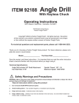
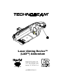
The laser exits the fixture through the same aperture as the light beam,
as shown in Figure 1. Technobeam was designed so that the laser is
visible if the dim flags are completely closed or open.
Laser aperture
Figure 1. The laser light exits the through the same aperture as the light
beam.
The laser should ideally be no more than 2” (5 cm) directly above the
center point of a perfectly round light beam, as shown in Figure 2:
Ideal laser spot
2" (5 cm) max
Figure 2. The ideal position of the laser is no more than 2” (5 cm) directly
above the center point of a perfectly round light beam.
In its ideal position, the laser path is parallel to the path of the light
and will stay 2” (5 cm) above the center point of the beam at any throw
TechnobeamLaser Aiming Device (LAD) Addendum
Overview
3
distance or mirror position.
If the laser becomes out of position, you might need to align it as
shown in the section titled “Maintenance” on page 8.
&RQWUROOLQJWKH/DVHU
You can control the laser in one of three ways:
•
•
•
The fixture’s menu system: Edit one of the fixture’s eight
onboard presets (scenes) using the PRST menu as described in the
next section.
Any DMX 512-compliant controller: See the section titled “DMX
Control of the Laser” on page 4.
The Technobeam LCD controller: See the controller’s user
manual.
0HQX&RQWURORIWKH/DVHU
Use the PRST menu to create scenes (presets) including the laser
aiming device. You access the LAD using the MACR construct from the
PRST menu.
The complete list of options controlling the laser aiming device (with
the MACR construct) is shown below:
•
•
•
LROF: laser aiming device OFF
LRON: laser aiming device ON continuously
LM01 to LM30: laser modulation levels. LM01 is “slow”
modulation at 4.25 times/sec and LM30 is “fast” modulation at 255
times/sec.
'0;&RQWURORIWKH/DVHU
This section explains how to control the laser using a DMX 512compatible controller.
1.
2.
3.
4.
4
Select a fixture number or DMX start channel for each fixture you wish
to control as described in Chapter 2 of the Technobeam User Manual.
Make sure you select the Technobeam full 18-channel protocol (TB
F from the Mode menu); otherwise, the laser aiming device will not
function.
Connect the fixtures to the controller as described in Chapter 2 of the
user manual.
See Appendix A of the user manual for details of DMX 512 control
(channels 17 and 18 in Technobeam full protocol as shown in Table A-1
of the user manual).
Controlling the Laser Technobeam Laser Aiming Device (LAD) Addendum
7URXEOHVKRRWLQJ
If laser fails to illuminate, the most likely reasons are lack of power or
a failed laser.
/DVHUJUDGXDOO\ORVHVSRZHU
This is normal; over time, the laser will gradually lose power until it
finally dims out entirely. If this is happening, contact High End
Systems Customer Service in one of the ways shown in “Getting Help”
on page 18.
/DVHULVRXWRISRVLWLRQ
Align the laser as shown in the section titled “Maintenance” on page 8.
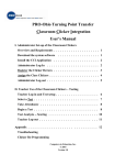
(PLVVLRQ,QGLFDWRU/('2))/DVHU2))
The laser circuit board is not receiving power. The Emission Indicator
LED is shown in Figure 3:
Laser aperture
Emission Indicator LED
Laser label
do not remove
Figure 3. Location of the laser aperture, required laser label and Emission
Indicator LED.
TechnobeamLaser Aiming Device (LAD) Addendum
Troubleshooting
5
1.
Unplug the fixture and remove the access door shown in Figure 4:
Door retaining screw
Access door
Figure 4. Removing the access door.
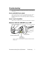
2.
Check all wiring connections shown in Figure 5:
LAD cables
Figure 5. LAD wiring connections.
6
3.
Check to make sure the cable labeled “LAD” is connected to the main
circuit board (with the LED display).
4.
Replace the access door, plug the fixture in and make sure you have
enabled the laser as shown in the section titled “Controlling the Laser”
Troubleshooting
Technobeam Laser Aiming Device (LAD) Addendum
on page 4.
5.
If the Emission Indicator LED and laser are both still OFF, contact High
End Systems Customer Service in one of the ways shown in “Getting
Help” on page 18.
(PLVVLRQ,QGLFDWRU/('21/DVHU2))
1.
The laser aiming device assembly is not receiving power. Check the
connection at the laser aiming device circuit board, shown in Figure 6.
The Emission Indicator LED is shown in Figure 3 on page 5.
LAD circuit board
Figure 6. The laser aiming device circuit board.
2.
If the cable connections are good, contact High End Systems Customer
Service in one of the ways shown in “Getting Help” on page 18.
/DVHU21(PLVVLRQ,QGLFDWRU/('2))
The most likely reason is a faulty Emission Indicator LED. Contact
High End Systems Customer Service as shown in “Getting Help” on page
18.
TechnobeamLaser Aiming Device (LAD) Addendum
Troubleshooting
7
0DLQWHQDQFH
WARNINGS
Before performing any service or
maintenance, make note of the following:
(1) Hot lamp may be an explosion hazard. Do
not open for 5 minutes after switching off.
Wear eye and hand protection when relamping.
(2) Equipment surfaces may reach
temperatures up to 70° C (158° F). Allow 5
minutes for cooling before handling.
(3) Disconnect power before re-lamping or
servicing.
(4) Never look directly at the lamp while
lamp is on.
(6) The procedures in this addendum are
intended to assist qualified service
personnel because Technobeam fixtures are
to be serviced by qualified service
personnel only.
/LYH&RPSRQHQWV
You will be accessing live components and adjusting the laser in the
next section. Take special care to avoid contacting high-voltage live
components, located in the area of the main circuit board, shown in
Figure 7.
8
Maintenance
Technobeam Laser Aiming Device (LAD) Addendum
High voltage components
are located in main
circuit board
Figure 7. High-voltage component location.
When you activate the laser, observe the following precaution:
Caution
Do not stare into the beam or view it directly
with optical instruments. Avoid accidental
exposure to laser radiation.
You must also observe the cautions in the section titled “Safety
Precautions” on page 16.
,QWURGXFWLRQ
You might need to realign the laser periodically in order to maintain its
optimal position—no more than 2” (5 cm) directly above the center
point of the light beam. If you align the laser in this way, the path of
the laser is parallel to the path of the light and will stay 2” (5 cm) above
the center point of the beam at any throw distance or mirror position.
However, the decision of whether or not to align the laser is entirely up
to you. If the laser strays from its optimal position, but it gives you
enough accuracy for your needs, you do not have to align it.
Figure 8 shows the ideal position of the laser from the center of a
TechnobeamLaser Aiming Device (LAD) Addendum
Maintenance
9
perfectly round light beam:
Ideal laser spot
2" (5 cm) max
Figure 8. The ideal position of the laser is no more than 2” (5 cm) directly
above the center of a perfectly round light beam.
$OLJQPHQW3URFHGXUH
The alignment procedure that follows takes advantage of
Technobeam’s built-in program storage capability to turn the laser ON.
1.
Follow the instructions in Chapter 1 of the user manual to select a
voltage setting and install a power cord cap, if you have not already
done so.
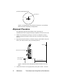
2.
Physically orient the fixture as shown in Figure 9 (the farther away the
wall is, the more accurate your positioning will be):
White wall
Stand fixture on its end handles
Sturdy, flat surface
such as a table
10 ft. (3 m) minimum
Figure 9. Orient the fixture directly facing a wall no less than 10 ft. (3 m)
away.
3.
10
Connect the fixture to an appropriately-rated power outlet. You will
Maintenance
Technobeam Laser Aiming Device (LAD) Addendum
hear sounds as wheels and motors seek their home positions; this is
normal.
4.
When the fixture has finished homing, press and hold the <Menu> key
until the LED display reads ADDR.
The next steps show how to turn the lamp ON.
5.
Use the <Up> and <Down> arrow keys to navigate to the TEST menu.
6.
Press <Enter>, then use the <Up> and <Down> arrow keys to navigate
to the LAMP option.
7.
Press <Enter>, then use the <Up> and <Down> arrow keys to select a
value of ON.
8.
Press <Enter>; the lamp should now be on (although you will not be
able to tell if the dim flags are closed).
The next steps show you how to access the fixture’s built-in
programming menu to begin aligning the laser.
9.
Keep pressing the <Menu> key until the ADDR menu is displayed.
10. Use the <Up> and <Down> arrow keys to navigate to the PRST menu.
11. Press <Enter>, then use the <Up> and <Down> arrow keys to navigate
to the EDIT menu option. The EDIT option allows you to create or edit
up to eight scenes which are stored in the fixture’s onboard memory.
12. Press <Enter>. Use the <Up> and <Down> arrow keys to select the
scene number of an unprogrammed scene. For example, selecting
SCN2 means you will edit scene number 2.
13. Press <Enter> to begin editing the scene you selected.
14. If you selected an unprogrammed scene, skip to Step 17 now;
otherwise, continue with the next step. If the fixture started making
noises of gears and wheels moving as soon as you selected the scene,
and the noises continue for more than a brief period of time, you
selected a programmed scene.
The next two steps show how to unprogram a scene; you need to
unprogram the scene in order to make sure all constructs are set to
default values. This is necessary only if all eight scenes are already
programmed.
15. Use the <Up> and <Down> arrow keys to navigate to the ZERO option.
16. Press <Enter>; you will be required to confirm the action by pressing
<Enter> again.
Step 17 through Step 22 shows how to open the shutter and set the dim
construct to full bright. You can skip these steps if you can clearly see
the light projected onto the wall.
17. Use the <Up> and <Down> arrow keys to navigate to the SHUT option.
18. Press <Enter>, then use the <Up> and <Down> arrow keys to select a
TechnobeamLaser Aiming Device (LAD) Addendum
Maintenance
11
value of OPEN.
19. Press <Enter> to accept your selection.
20. Use the <Up> and <Down> arrow keys to navigate to the DIM option.
21. Press <Enter>, then use the <Up> and <Down> arrow keys to select a
value of D255 (full bright).
22. Press <Enter> to accept your selection.
You should now see the white, round shape of the beam projected onto
the wall or white surface.
• If the beam is round (not oval) in shape, continue with Step 31.
• If the beam is not round in shape, see the next step.
23. Make sure the fixture is oriented directly at the wall, not at an angle. If
the fixture is at an angle to the wall, it might be impossible to align the
laser properly.
24. Use the <Up> and <Down> arrow keys to navigate to the TILT option.
25. Press <Enter>, then use the <Up> and <Down> arrow keys to adjust the
mirror position until the beam is round.
26. Press <Enter> to accept your selection for TILT.
27. If the beam needs further adjustment, use the <Up> and <Down> arrow
keys to navigate to the PAN option.
28. Press <Enter>, then use the <Up> and <Down> arrow keys to adjust the
mirror position.
29. Press <Enter> to accept your selection for PAN.
30. Continue adjusting the mirror using PAN and TILT until the beam is as
round as possible.
If you cannot see the beam at all, the lamp might be off. Select LAMP
from the Test menu and make sure a value of ON is displayed; see Step
5 through Step 8. (If the lamp still does not come on, wait a few
minutes and try again.)
31. Use the <Up> and <Down> arrow keys to navigate to the FCUS option.
32. Press <Enter>, then use the <Up> and <Down> arrow keys to focus on
the edge of the beam until it is sharp.
33. Continue moving the fixture and focusing on the edge of the beam
until the beam is as round as possible, and sharply in focus.
34. When you have focused the beam, press <Enter>.
12
Maintenance
Technobeam Laser Aiming Device (LAD) Addendum
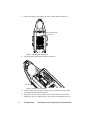
35. Find the approximate center of the beam using either a tape measure,
ruler or a piece of string, as shown in Figure 10.
1
Extend the tape measure or string down
at the widest part of the beam
2
Lightly mark on the wall
along the string
Line you made in Step 2
Ideal laser spot
2" (5 cm) max
3
Extend the string across the beam's
widest point. Laser should be no more
than 2" (5 cm) above the string, along
the center line.
Figure 10. Locating the center point of the projected light beam. The laser
should be no more than 2” (5 cm) above the center.
36. Once you have marked the center point of the beam, keep pressing the
<Menu> key until the ADDR option is displayed.
37. Use the <Up> and <Down> arrow keys to navigate to the TEST menu.
38. Press <Enter>, then use the <Up> and <Down> arrow keys to navigate
to the LAMP option.
39. Press <Enter>, then select a value of OFF.
40. Press <Enter>. The lamp now shuts off.
41. Keep pressing the <Menu> key until the ADDR option is displayed.
42. Use the <Up> and <Down> arrow keys to navigate to the PRST menu.
43. Use the <Up> and <Down> arrow keys to navigate to the EDIT option.
44. Press <Enter>, then use <Up> and <Down> arrow keys to navigate to
the SCN2 option (this selects scene number 2; select the same scene
you selected in Step 12.
Caution
Do not stare into the laser beam or view it
directly with optical instruments.
TechnobeamLaser Aiming Device (LAD) Addendum
Maintenance
13
45. Press <Enter>, then use the <Up> and <Down> arrow keys to navigate
to the MACR option.
46. Press <Enter>, then use the <Up> and <Down> arrow keys to select
LRON (laser on continuously).
47. Press <Enter> to accept your selection.
48. Look at the wall where the beam is projected onto to determine if the
laser is on.
49. If the laser does not come on, see the section titled “Troubleshooting”
on page 5; otherwise, continue with the next step.
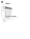
50. Figure 11 shows the 3 mounting/alignment screws located on the laser
aiming device assembly. See the instructions that follow the drawing.
2
1
3
Mounting/alignment screws
Figure 11. The laser aiming device assembly has three screws that can be
used to adjust the position of the laser.
Alignment screws 1 and 3 (shown in Figure 11) move the laser
horizontally, and screw 2 moves the laser vertically. Use the three
alignment screws to adjust the position of the laser so that it is no
more than 2” (5 cm) directly above the center point of the beam, shown
in Figure 2 on page 3.
51. After you tighten/loosen each screw, release pressure from the
screwdriver before looking at the laser position on the wall; having
pressure on the screw can change the laser’s position. Do not force the
screws or fully tighten them because the ends of the screws might
interfere with the dim flags.
Hint:
If you have difficulty aligning the laser or turning the
screws, loosen all three screws and start over.
52. Continue repeating the procedure until the laser is aligned. (If you
cannot get your laser exactly at position shown in Figure 8 on page 10,
but it is still at a position you think will give you enough accuracy for
your needs, you are finished.)
53. When you’re finished, replace the access door shown in Figure 4 on
page 6.
14
Maintenance
Technobeam Laser Aiming Device (LAD) Addendum
6SHFLILFDWLRQV
Class 3a laser product
Beam divergence angle: 0.2mRad to 0.3mRad
Maximum output (continuous): 5mW at 630-650nm
Maximum output (pulsed): <2.5mW
Pulse modulation: 4.25Hz to 255Hz @ 50% duty cycle
Pulse duration: 1.96ms to 117ms
Pulse energy: 9.8µJ to 585µJ
6DIHW\6WDQGDUGV
EN60825-1, 1994
21 CFR 1040
AVOID
EXPOSURE
Laser radiation is emitted from this aperture
Emission indicator
LASER RADIATION - AVOID
DIRECT EYE EXPOSURE
Max output: 5mW at 630-650 nm
CLASS 3a LASER PRODUCT
LASER RADIATION - DO NOT
STARE INTO BEAM OR
VIEW DIRECTLY WITH
OPTICAL INSTRUMENTS
Max output: 5mW at 630-650 nm
CLASS 3a LASER PRODUCT
Cert. to EN 60825-1, 1994
and 21 CFR 1040
Laser aiming device assembly
(inside fixture)
TechnobeamLaser Aiming Device (LAD) Addendum
Specifications
15
6DIHW\3UHFDXWLRQV
1.
CAUTION: Use of controls or adjustments or performance of
procedures other than those specified herein may result in hazardous
radiation exposure.
2.
Using the Laser Aiming Device with any fixture other than Technobeam
may result in damage to both the laser and the fixture as well as
exposure to laser radiation.
3.
Do not point the laser at an audience.
4.
Precautions should be taken to ensure that the laser beam is not
unintentionally directed at mirror-like (specular) surfaces (most
importantly, at flat mirror-like surfaces).
5.
Only qualified and trained employees approved by a laser safety
officer should be assigned to install, adjust and operate the laser
equipment.
6.
When not in use, the laser (fixture) should be stored in a location where
unauthorized personnel cannot gain access.
7.
Do not remove the label shown in Figure 3 on page 5.
8.
Areas in which this product is used should be posted with a standard
laser warning sign.
9.
Do not stare directly into the beam and do not view the beam with
optical instruments.
10. The laser path should be located well above or below eye level.
11. The laser beam should be terminated at the end of its useful path.
12. Consult local and state laws regarding laser use and possible
registration requirements.
16
Safety Precautions Technobeam Laser Aiming Device (LAD) Addendum
Declaration of Conformity
according to ISO/IEC Guide 22 and EN45104
Manufacturer’s name:
Manufacturer’s address:
Distributor’s name:
Distributor’s address:
Lightwave Research
2217 West Braker Lane
Austin, Texas 78758 U.S.A.
High End Systems Inc.
2217 West Braker Lane
Austin, Texas 78758 U.S.A.
Declares that the product
Product Name:
Product Number:
Product Options:
Laser Aiming Device
Laser Aiming Device
All
conforms to the following EEC directives:
73/23/EEC, as amended by 93/68/EEC
89/336/EEC, as amended by 92/31/EEC and 93/68/EEC
Equipment referred to in this declaration of conformity first manufactured in
1998 in compliance with the following standards:
Safety:
EN 60825-1, 1994
EMC:
EN 55022,
IEC 801-2,
IEC 801-3,
IEC 801-4,
Class A ITE
1991 Level 2 (4/8 kV)
Draft 5 Level 2 (3 V/m)
1988 Level 2 (1 kV/0.5 kV)
U.S.A., February 5, 1998
Kenneth Stuart Hansen, Compliance Engineer
TechnobeamLaser Aiming Device (LAD) AddendumDeclaration of Conformity 17
*HWWLQJ+HOS
U.S., the Americas and
Europe
Service address:
2227 West Braker Lane
Austin, TX 78758 U.S.A.
From 8 a.m. to 6 p.m. (U.S. Central time) Monday
through Friday:
(800) 890-8989
24-hour FAX:
(512) 834-9195
24-hour voice mail:
(512) 837-3063 or
(800) 890-8989
8200 Haskell Avenue
Van Nuys, California 91406
Voice:
(818) 947-0550
Fax:
(818) 908-8975
18
Singapore
Voice:+65 742 8266
FAX:+65 743 9322
24-hour Customer
Service World Wide
Web site
http://info.highend.com/service/service.html
High End Systems
World Wide Web site
http://www.highend.com
Getting Help
Technobeam Laser Aiming Device (LAD) Addendum
TechnobeamLaser Aiming Device (LAD) Addendum
Getting Help
19