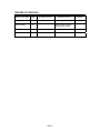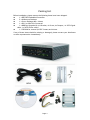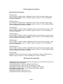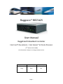
1
Ruggcore™ REC5425
User Manual
Ruggdized Embedded Controller
Intel Core™2 Duo (Merom) / Intel Celeron™ M (Yonah) Processor
(2nd Edition 03/03/2009)
All information is subject to change without notice.
Approved by
Checked by
Prepared by
Ming
Hank
Jack
Page 1
RECORD OF REVISION
Version and Date
Page
Old Description
New Description
Jan.20 2009
all
Preliminary Release
Mar.03 2009
all
Adding Product SKU &
ordering information
Page 2
Remark
Acknowledgments
All other products’ name or trademarks are properties of their respective owners.
Award is a trademark of Award Software International, Inc.
®
Intel , Core
®
TM
2 Duo, Core
TM
Duo, Core
TM
®
Solo and Celeron M are trademarks of
Intel Corporation.
®
Microsoft Windows is a registered trademark of Microsoft Corp.
IBM, PC/AT, PS/2, and VGA are trademarks of International Business Machines
Corporation.
Please be notified that all other products’ name or trademarks not be mentioned
above are properties of their respective owners.
Page 3
Packing List
Before installation, please ensure the following items have been shipped:
z
1 x REC5425 Embedded Controller
z
2 x Wallmount Brackets
z
1 x Screw Package (M3 x 16mm)
z
1 x DVI-I to VGA Port Connector
z
1 x HDD Bay Upgrade Kit (1x Bracket, 4x Screw, 4x Damper, 1x SATA Signal
cable, 1x SATA Power cable)
z
1 x CD-ROM for manual (in PDF format) and drivers
If any of these items should be missing or damaged, please contact your distributor
or sales representative immediately.
Page 4
Ordering Information
Model Number Description
REC5425-A01
Intel Celeron M 1.86GHz (440), 1GB RAM, Fanless, DC9~36V input, LANx1, Giga
LANx1, USBx4, COMx6, DVI-Ix1, HDMIx1 (option), LVDSx1, CF Slot, HDD Bayx1,
PCI Slotx1, DI/DOx4
REC5425-A01-01
Intel Celeron M 1.86GHz (440), 1GB RAM, Fanless, DC9~36V input, LANx1, Giga
LANx1, USBx4, COMx6, DVI-Ix1, HDMIx1 (option), LVDSx1, CF Slot, 80GB HDD with
XPe pre-installation, PCI Slotx1, DI/DOx4
REC5425-A02
Intel Core2Duo 2.16GHz (T7400), 1GB RAM, Fanless, DC9~36V input, LANx1, Giga
LANx1, USBx4, COMx6, DVI-Ix1, HDMIx1 (option), LVDSx1, CF Slot, HDD Bayx1,
PCI Slotx1, DI/DOx4
REC5425-A02-01
Intel Core2Duo 2.16GHz (T7400), 1GB RAM, Fanless, DC9~36V input, LANx1, Giga
LANx1, USBx4, COMx6, DVI-Ix1, HDMIx1 (option), LVDSx1, CF Slot, 80GB HDD with
XPe pre-installation, PCI Slotx1, DI/DOx4
REC5425-A03
Intel Core2Duo 1.66GHz (T5500), 1GB RAM, Fanless, DC9~36V input, LANx1, Giga
LANx1, USBx4, COMx6, DVI-Ix1, HDMIx1 (option), LVDSx1, CF Slot, HDD Bayx1,
PCI Slotx1, DI/DOx4
REC5425-A03-01
Intel Core2Duo 1.66GHz (T5500), 1GB RAM, Fanless, DC9~36V input, LANx1, Giga
LANx1, USBx4, COMx6, DVI-Ix1, HDMIx1 (option), LVDSx1, CF Slot, 80GB HDD with
XPe pre-installation, PCI Slotx1, DI/DOx4
REC5425-B01
Barebone, Fanless, DC9~36V input, LANx1, Giga LANx1, USBx4, COMx6, DVI-Ix1,
HDMIx1 (option), LVDSx1, CF Slot, HDD Bayx1, PCI Slotx1, DI/DOx4
Optional Accessories
840612073000 AC-to-DC Adapter DC12V/7.0A 84W (max), with Phoenix Power Plug
476000001001 Din-rail Bracket
810501201000 PS/2 Y Cable for Keyboard and Mouse
810218001020 DVI-I to DVI-D & DVI-I to VGA Port Y Cable
800105005010 LVDS Cable, for CM1236 & CM1555 panel, 500mm
800105005020 LVDS Cable, for AU1744 & AU1954 panel, 500mm
810518001030 HDMI cable
810618301015 Power Cable USA Type
810618301070 Power Cable Europe Type
Page 5
Safety & Warranty
1. Read these safety instructions carefully.
2. Keep this user's manual for later reference.
3. Disconnect this equipment from any AC outlet before cleaning. Do not use liquid
or spray detergents for cleaning. Use a damp cloth.
4. For pluggable equipment, the power outlet must be installed near the equipment
and must be easily accessible.
5. Keep this equipment away from humidity.
6. Put this equipment on a firm surface during installation. Dropping it or letting it
fall could cause damage.
7. Make sure the voltage of the power source is correct before connecting the
equipment to the power outlet.
8. Position the power cord so that people cannot step on it. Do not place anything
over the power cord.
9. All cautions and warnings on the equipment should be noted.
10. If the equipment is not used for a long time, disconnect it from the power source
to avoid damage by transient over-voltage.
11. Never pour any liquid into an opening. This could cause fire or electrical shock.
12. Never open the equipment. For safety reasons, only qualified service personnel
should open the equipment.
13. If any of the following situations arises, get the equipment checked by service
personnel:
a. The power cord or plug is damaged.
b. Liquid has penetrated into the equipment.
c. The equipment has been exposed to moisture.
d. The equipment does not work well, or you cannot get it to work according to
the user’s manual.
e. The equipment has been dropped and damaged.
f. The equipment has obvious signs of breakage.
14. DO NOT LEAVE THIS EQUIPMENT IN AN ENVIRONMENT WHERE THE STORAGE
TEMPERATURE IS BELOW -20°C (-4°F) OR ABOVE 70°C (158°F). IT MAY DAMAGE THE
EQUIPMENT.
FCC Safety
This device complies with Part 15 FCC Rules.
Operation is subject to the following two conditions:
(1) this device may not cause harmful interference, and
(2) this device must accept any interference received including
interference that may cause undesired operation.
Page 6
TABLE OF CONTENT
RECORD OF REVISION ........................................................................................................ 2
1.0 INTRODUCTION......................................................................................................... 8
2.0 HARDWARE INSTALLATION ......................................................................................... 10
3.0 AWARD BIOS SETUP.................................................................................................... 28
4.0 DRIVER INSTALLATION................................................................................................ 41
5.0 APPENDIX................................................................................................................... 42
Page 7
1.0 INTRODUCTION
1.1 About Ruggcore™ Embedded Controller
The REC5425 Embedded Controller system’s design concept not only focuses on the fast
expanding Machine Automation market but also the Industrial Automation industry. The
REC5425 can provide one mini PCI-E slot (internal) and one mini PCI slot (internal) for
expansion.
A solid sealed aluminum case provides vibration and dust resistance while also providing
a passive cooling solution. The REC5425 provides system integrators with a turn-key
solution and versatile application development path to fulfill the diversified market
demand.
The REC5425 can be used as a standalone system, wall-mounted, DIN-rail mounted. The
system accepts a wide range of power supplies (DC power in) and comes in a footprint of
only 262(W) x 86(H) x 184 (D) mm. The rugged aluminum case not only provides great
protection from EMI, shock/vibration, cold and heat, but also passive cooling for quiet
fanless operation.
The REC5425 equips the rich I/O by offering 1 x DVI-I (or 1 x HDMI) and 1 x LVDS interface
for dual display, 4 x USB 2.0 ports,1 x Giga LAN port, 1 x 10/100 LAN port and 6 x COM
ports; packed into a small rugged unit and powered by an Intel Core2 Duo/ Core Duo/
Core Solo/ Celeron M processor. It also supports a wide range of input voltages from 9V
DC to 36V DC. The REC5425 Embedded Computer supports Compact Flash card for
storage options and it can provide the diversified application field.
Therefore REC5425’s expandable function, compact size combined with fanless design
and highly efficient heat conduction mechanism can fulfill any rugged technical
application in industrial automation, factory control, test instrumentation and safety
surveillance.
1.2 FEATURES
z
z
z
z
Intel® Core™2 Duo/ Core Duo/ Core Solo/ Celeron M Based Fanless Design
Rich IO (4 USB, 6 COM, 2 Ethernet)
Rich Video [LVDS, DVI-I or HDMI (option)]
Stackable Chassis Upgrade Design with Easy Expansion Solution Kit
1.3 SPECIFICATIONS:
System
Processor
Intel Core 2 Duo (Merom), Core Duo, Core Solo/ Celeron M
(Yonah)
Chip Set
Intel945GME + ICH-7M
System Memory
DDRII SODIMM x 1, Max. 2GB (DDRII 400/533/667)
Ethernet
Intel EP82562ET, 10/100 Base-TX
Intel 82573 GbE (Gigabit Ethernet)
Storage
CF Card & HDD Bay
Audio
ALC655, Line-Out, MIC
Page 8
I/O Interface-Front
PWR/HDD LED, DC-In, Power on SW, KB/MS
RJ45 x2, USB x4, COMx6 (RS232 x5, RS232/422/485 x1)
I/O Interface-Rear
Audio Phone Jack (Line-out, MIC-in)
DVI-I or HDMI (option),LVDS Connector, CF Connector
BIOS
Award
Wake On LAN
YES
Watchdog Timer
Generates a time-out system reset
H/W Status Monitor
Supports power supply voltages, fan speed and
temperature monitoring
Expansion Interface
Mini PCI (internal)
Mini PCI-E (internal)
PCI Slot (external)
Power Supply
1. DC Input:
Input voltage: 9V DC ~ 36V DC
Mechanical
Construction
Rugged Aluminum Alloy chassis
Mounting
Wallmount, Desktop, DIN Rail
Dimension
262mm (W) x 86mm(H) x 184mm(D)
Net Weight
4.6Kg
Environment
Operating Temperature
-15°C ~ 55°C ( 5°F ~ 131°F) - CFD
Storage Temperature
-20°C ~ 70°C (-4°F ~-158°F)
Operating Humidity
5~90% @ 40°C, non-condensing
Vibration:
5g rms / 5~500Hz / random operation (CFD);
1g rms / 5~500Hz / random operation (HDD);
Shock:
50g peak acceleration (11msec. duration)(CFD)
20g peak acceleration (11msec. duration) (HDD)
Certification
CE/FCC class A
Page 9
2.0 HARDWARE INSTALLATION
2.1 REC5425 Dimension
Page 10
2.2 CPU Board Mechanical Drawing
Component Side
Solder Side
Page 11
2.2.1 List of Connectors
The CPU board has a number of connectors that allow you to configure your system
to suit your application.
The table below shows the function of the board's connectors:
2.2.2 Setting Jumpers
You configure your card to match the needs of your application by setting jumpers. A
jumper is the simplest kind of electric switch. It consists of two metal pins and a
small metal clip (often protected by a plastic cover) that slides over the pins to
connect them. To “close” a jumper you connect the pins with the clip.
To “open” a jumper you remove the clip. Sometimes a jumper will have three pins,
labeled 1, 2 and 3. In this case you would connect either pins 1 and 2 or 2 and 3.
A pair of needle-nose pliers may be helpful when working with jumpers.
If you have any doubts about the best hardware configuration for your application,
contact your local distributor or sales representative before you make any change.
Generally, you simply need a standard cable to make most connections.
Page 12
2.3 Carrier Board Mechanical Drawing
Jumpers and Connectors Location in Carrier Board
Component Side
Solder Side
Page 13
2.3.1 List of Connectors
Location
DC1
CN6
CN7
CN8
CN9
CN10
CN11
CN12
CN14, CN15, CN17, CN18
CN16
CN20
CN21
CN22
DVI-I
USB1, USB2
LAN1, LAN2
MPCI1
PCI1
CFD1
SATA1, 2
COM1, COM2
FAN1,2
PWR1
PWRBT1
LPT1
JP4,JP5,JP10,JP13
JP12, JP15, JP16
JP11
CMOS1
JP6
Function
DC Power Input Connector
LPC and Digital I/O Connector.
HDMI Connector
SDVO Connector
USB Connector
XTX Connector
LVDS Connector
I2C Connector
COM3,4,5,6 Connector
Front Panel Connector
Keyboard/Mouse Connector
IrDA Connector
Mini Card Connector
DVI + VGA Connector
Dual USB Ports
RJ45 Connector
MINI PCI CONNECTOR
PCI Slot
Compact Flash Connector
SATA Connectors
D-sub 9 pin Connector
FAN Connector
HDD POWER Connector
POWER BUTTON Switch
PARALLEL PORT Connector
COM Port Power +12V/+5V/RING
Selection
COM2 RS232/RS422/RS485 Selection
Compact Flash Voltage Selection
CMOS Clear Selection
Backlight / LVDS Power Selection
Page 14
2.4 External I/O Connectors
Front View
Rear View
Page 15
1. DC-IN: DC Power Input
Pin
1
2
3
Signal
+9~36V DC input (V+)
Voltage Ground (0V)
Cable Shading Ground
Please pay special attention to make sure the plus voltage input in pin1 (V+), zero
voltage input in pin2. Mix these two pins may cause product damage. Pin 3 is system
shading ground.
2. CN6: LPC and Digital IO Connector.
LPC Connector
Pin
Signal
Pin
Signal
1
+3.3V
2
LPC_FRAME#
3
LPC_AD0
4
LPC_AD1
5
LPC_AD2
6
LPC_AD3
7
GND
8
LPC_CLK33
9
INT_SERIRQ
10
ICH_DRQ#0
11
GND
12
LPC_RST#
13
PCI_PME#
14
+5V
15
+5VDUAL
16
GND
17
SIOGPIO56
18
SIOGPIO57
19
SIOGPIO60
20
SIOGPIO61
21
SIOGPIO51
22
SIOGPIO52
23
SIOGPIO45
24
SIOGPIO47
3. CN8: SDVO Connector
SDVO Connector
Pin
Signal
1
GND
3
SDVOC_CLK+
5
SDVOC_G7
GND
9
SDVOC_INT+
11
SDVOC_B-
Pin
2
4
6
8
10
12
Signal
SDVOC_CLKGND
SDVOC_G+
SDVOC_INTGND
SDVOC_B+
Page 16
13
15
17
19
21
23
25
27
29
GND
SDVOC_R+
NC
GND
SDVO_CLDATA
+3.3V
+5V
NC
NC
14
16
18
20
22
24
26
28
30
SDVOC_RGND
NC
SDVO_CLCLK
SDVO_RST#
+2.5V
GND
NC
NC
4. CN9: USB Connector (Internal Pin Header)
Pin
Signal
1
USB Power
2
USBD43
USBD4+
4
GND
5. CN11: LVDS Connector
LVDS Connector
Pin
Signal
1
BLON#
3
LVDS Power
5
LA_CLKN
7
LVDS Power
9
LA_DATAN0
11
LA_DATAN1
13
LA_DATAN2
15
LA_DATAN3
17
L_DDC_DATA
19
LB_DATAN0
21
LB_DATAN1
23
LB_DATAN2
25
LB_DATAN3
27
LVDS Power
29
LB_CLKN
Pin
2
4
6
8
10
12
14
16
18
20
22
24
26
28
30
Signal
L_BKLTCTL
GND
LA_CLKP
GND
LA_DATAP0
LA_DATAP1
LA_DATAP2
LA_DATAP3
L_DDC_CLK
LB_DATAP0
LB_DATAP1
LB_DATAP2
LB_DATAP3
GND
LB_CLKP
6. CN12: I2C Connector
Pin
1
2
3
4
Signal
+3.3V
I2C_CLK
I2C_DAT
GND
Page 17
7.
CN14: COM3 Connector (Internal)
CN15: COM4 Connector (Internal)
CN17: COM5 Connector (Internal)
CN18: COM6 Connector (Internal)
COM3,
Pin
1
3
5
7
9
8.
COM4, COM5, COM6
Signal
DCD3
TXD3
GND
RTS3
RING3
JP4:
JP13:
JP5:
JP10:
+12V
2
4
●
○
■
○
1
+5V
2
○
□
COM3
COM4
COM5
COM6
Pin
2
4
6
8
10
+12V/+5V/RING
+12V/+5V/RING
+12V/+5V/RING
+12V/+5V/RING
Signal
RXD3
DTR3
DSR3
CTS3
NC
Selection
Selection
Selection
Selection
6
○
○
3
5
4
●
●
6
○
○
1
3
5
RING (Default)
2
4
6
○
○
●
□
○
●
1
9.
3
5
COM1, COM2:
D-Sub 9 Pin COM Port Connector.
10. JP12, JP15, JP16:
JP12
JP15
JP16
1
●
1
●
1
●
COM2 RS232/RS422/RS485 Selection
Default
RS232
2
3
●
○
2
3
●
○
2
3
●
○
1
●
1
○
1
○
RS422
2
3
●
○
2
3
●
●
2
3
●
●
Page 18
1
○
1
○
1
●
RS485
2
3
●
●
2
3
●
●
2
3
●
○
11. CN16:
Front Panel Connector
Front Panel Connector
Pin
Signal
Pin
Signal
1
LCD_UP
2
LCD_DW
3
GND
4
PANSWH#
5
7
9
11
13
POWERLED
NC
SP_UP
GND
+5V
6
8
10
12
14
HDD_LED
GND
SP_DW
HWRST#
+3.3V
12. CN21:
IrDA Connector
Pin
Signal
1
+5V
2
NC
3
IRRX
4
GND
5
IRTX
13. FAN1, FAN2:
Pin
Signal
1
GND
2
FAN Power
3
FAN_TAC
FAN Connector
14. PWR1:
SATA HDD Power Connector
Pin
Signal
1
+5V
2
GND
3
+12V
4
GND
15. PWRBT1: Power on/off Button
Page 19
16. LPT1:
Parallel Port Connector
PARALLEL PORT
Pin
Signal
Pin
Signal
1
STB2
AFDX
3
PTD0
4
ERRX
5
PTD1
6
PAR_INITX
7
PTD2
8
SLINX
9
PTD3
10
GND
11
PTD4
12
GND
13
PTD5
14
GND
15
PTD6
16
GND
17
PTD7
18
GND
19
ACKX
20
GND
21
BUSY
22
GND
23
PE
24
GND
25
SLCT
26
GND
17. JP11:
Compact Flash Voltage Selection
+3.3V Power for Compact Flash
1
2
3
■
●
○
+5V Power for Compact Flash
1
2
3
□
●
●
Default
18. CMOS1: CMOS Clear Selection
Clear CMOS
1
2
3
□
●
●
Normal Operation
1
2
3
■
●
○
Default
19. JP6:
Backlight / LVDS Power Selection
+3.3V Power for Backlight
Default
2
4
6
8
10
●
○
○
○
○
■
○
○
○
○
1
3
5
7
9
+5V Power for Backlight
2
4
6
8
10
○
●
○
○
○
□
●
○
○
○
1
3
5
7
9
Page 20
+3.3V Power for LVDS
Default
2
4
6
8
10
○
○
●
○
○
□
○
●
○
○
1
3
5
7
+5V Power for LVDS
2
4
6
8
○
○
○
●
□
○
○
●
1
3
5
7
9
10
○
○
9
+12V Power for LVDS
2
4
6
8
10
○
○
○
○
●
□
○
○
○
●
1
20.
CN10:
CN7:
CN20:
CN22:
DVI-I:
USB:
LAN1:
LAN2:
MPCI:
PCI1:
CFD1:
SATA1:
SATA2:
3
5
7
9
Standard Connectors:
XTX Connector Raw A,B,C & D
HDMI Connector
PSII Key Board/Mouse Connector
Mini Card Connector (Mini PCI-e + USB)
DVI-I Connector
Dual USB Connector
RJ45 Connector
RJ45 Connector
Mini PCI Connector
PCI Slot and PCI-E Slot
Compact Flash Connector.
SATA Connector
SATA Connector
Page 21
2.5 System Installation
1. Connect the cables into the appropriate connectors as below.
2.1 Option 1: DVI-D or VGA output
Please choose DVI-I Y cable as your option. Connect the DVI-I Y cable into the DVI
connector as below if you use DVI-D or VGA input display. Before you enable DVI output
function, you need to setup BIOS. Please refer to (Chapter3 Award BIOS Setup 4) for
detail.
Page 22
2.2 Option 2: VGA Output
Please choose DVI-I to VGA converter as your option
Connect the DVI-I to VGA converter into the DVI connector as below if you choose VGA
input display as default.
Page 23
Connect the VGA cable into the DVI-I converter as below.
2.3 Option 3: HDMI Output (option)
Connect the HDMI cable into the HDMI connector as below if you choose HDMI input high
quality display. Before you enable HDMI output function, you need to setup BIOS. Please
refer to (Chapter3 Award BIOS Setup 4) for detail.
Page 24
2.4 Option 4: Choose LVDS cable as your option
Connect the LVDS cable into the LVDS connector as below if you choose LVDS input panel.
Before you enable LVDS output function, you need to setup BIOS. Please refer to
(Chapter3 Award BIOS Setup 4) for detail
Page 25
3. Compact Flash Card Installation
The Upper Side of CF Card
Please be noted that the user should turn the CF card to the bottom side (180 degree)
and then insert the CF card into the slot
Page 26
4. Power On your system
Before power on your system, please measure the power signal in advance and double
confirm the data with below table.
Pin
1
2
3
Signal
+9~36V DC input (V+)
Voltage Ground (V-)
Cable Shading Ground
Please pay special attention to make sure the plus voltage input is in pin1 (V+), and
zero voltage input is in pin2 (V-). Mix these two pins may cause product damage.
Pin 3 is system shading ground.
Press the PWR-ON button and then begin to run your system
Page 27
3.0 AWARD BIOS SETUP
3.1 Award BIOS Setup
The BIOS setup, also called CMOS setup, is a crucial part of the proper setting up of
Ruggcore. The BIOS (Basic Input Output System) tells the operating system the
characteristics of the main basic components of Ruggcore. Because of this, an
incorrectly set up BIOS can result in some devices not being recognized by the
operating system.
Getting into the Award BIOS
Cold boot Ruggcore and when you see the first screen showing in monitor, press the
Delete key repeatedly till you get a blue screen titled.
When you successfully get into the BIOS setup, you will be presented with the
following menu.
Setup 1: The Main BIOS Menu.
The sections that follow provide guidelines on how to set up the various settings in
each section of the BIOS. We have concentrated only on those settings that may
need changing, if a setting does not appear in this document, leave it as you found
it.
Press Enter on a main menu option to go into that section.
To return to the Main Menu from within a section, press Escape.
Screen 1
Page 28
Setup 2: Standard CMOS Features
Here you can setup the basic BIOS features such as date and time. Use the arrow
keys to move around and press enter to select the required option. You can specify
what IDE or SATA devices you have such as Hard drive, CF device etc. The easiest
way to setup the devices is by leaving it set to auto. This allows the BIOS to detect
the devices automatically so you don't have to do it manually. At the bottom, it also
displays the total memory in your system. Verify that your hard disk or CF device
have been correctly detected in the shaded fields.
Screen 2
Page 29
Setup 3: Advanced BIOS Features
As you can see from screen 3, there are numerous advance settings which you can
select if required. For most cases leaving the default setting should be adequate.
Screen 3
As you can see from the screen 4, the first and second boot device is set to Hard Disk.
This ensures that the hard disk is read first when the system boots, and therefore
can boot from boot disk. The third is set to CD ROM.
Screen 4
Page 30
Setup 4: Advanced Chipset Features
Here you can setup the contents of the chipset buffers. It is closely related to the
hardware and is therefore recommended that you leave the default setting unless
you know what you are doing. Having an incorrect setting can make your system
unstable.
Screen 5
Choose Boot Display in VGA Setting Selection Items
Screen 6
Page 31
Select [CRT+LCD] item for LVDS output option:
Screen 7
Select [CRT+DVI or HDMI] item for DVI or HDMI output option:
Screen 8
Page 32
Setup 5: Integrated Peripherals
This menu allows you to change the various I/O devices such as IDE controllers, serial
ports, keyboard, USB, and LAN. You can make changes as necessary.
Screen 9
Screen 10
Page 33
Setup 6: Power Management Setup
The power management allows you to setup various power saving features, when the
PC is in standby or suspend mode.
Screen 11
Screen 12
Page 34
Setup 7: PnP/PCI Configurations
This menu allows you to configure your PCI slots. You can assign IRQ's for various PCI
slots. It is recommended that you leave the default settings, BIOS can automatically
configure all the boot and plug & play compatible devices. You may choose manual
mode when you want to change PCI device resources.
Screen 13
Screen 14
Page 35
Setup 8: PC Health Status
This menu displays the current CPU, chipset, system temperature, fan speeds, and
voltages.
Screen 15
Screen 16
Page 36
Setup 9: Load Fail-Safe Defaults
If you made changes to the BIOS and your system becomes unstable as a result, you
can change it back to default. However if you made many changes and don't know
which one is causing the problem, your best bet is to choose the option "Load Fail
Safe Defaults" from the BIOS menu. This uses a minimal performance setting, but the
system would run in a stable way. From the dialog box Choose "Y" followed by enter
to load Fail-Safe Defaults.
Screen 17
Page 37
Setup 10: Load Optimized Defaults
Like the Fail-Safe mode above, this option loads the BIOS default settings, but runs
the system at optimal performance. From the dialog box Choose "Y" followed by
enter to load Optimized Defaults.
Screen 18
Page 38
Steup11: Set Password
There are two kinds of password protect your BIOS, Supervisor and User password,
you can specify a password and make sure you don't forget the password. You will be
asked for password when you into BIOS setup manual.
Screen 19
Screen 20
Page 39
Setup 12: Save and Exit Setup
To save any changes you made to the BIOS you must choose this option. From the
dialog box choose "Y".
Screen 21
Setup 13: Exit without Saving
If you don't want to save changes made to the BIOS, choose "N" from the dialog box.
Screen 22
Page 40
4.0 DRIVER INSTALLATION
The REC5425 comes with a CD-ROM that contains all drivers and utilities that meet
your needs.
Follow the sequence below to install the drivers:
Step 1 – Install INF Driver
Step 2 – Install VGA Driver
Step 3 – Install LAN Driver
Step 4 – Install Audio Driver
USB 2.0 Drivers are available for download using Windows Update for both Windows
XP and Windows 2000. For additional information regarding USB 2.0 support in
Windows XP and Windows 2000, please visit www.microsoft.com/hwdev/usb/.
Please read instructions below for further detailed installations.
4.1 Installation:
Insert the REC5425 CD-ROM into the CD-ROM Drive. And install the drivers from Step
1 to Step 6 in order.
Step 1 – Install INF Driver
1. Click on the Step 1 - INF folder and then double click on the Setup.exe
2. Follow the instructions that the window shows
3. The system will help you install the driver automatically
Step 2 – Install VGA Driver
1. Click on the Step 2 - VGA folder and select the folder of OS your system is
2. Double click on the .exe file
3. Follow the instructions that the window shows
4. The system will help you install the driver automatically
Step 3 – Install LAN Driver
1. Click on the Step 3 - LAN folder and double click on the PRO2KXP.exe
2. Follow the instructions that the window shows
3. The system will help you install the driver automatically
Step 4 – Install Audio Driver
1. Click on the Step 4 - AC97 folder and select the folder of OS your system is
2. Double click on the .exe file
3. Follow the instructions that the window shows
4. The system will help you install the driver automatically
Page 41
5.0 APPENDIX
5.1 Programming the watchdog timer
A.1 Programming
REC5425 utilizes ITE 8712 chipset as its watchdog timer controller.
Below are the procedures to complete its configuration and the REC5425 intial
watchdog timer program is also attached based on which you can develop
customized program to fit your application.
Configuring Sequence Description
After the hardware reset or power-on reset, the ITE 8712 enters the normal mode
with all logical devices disabled except KBC. The initial state (enable bit) of this
logical device (KBC) is determined by the state of pin 121 (DTR1#) at the falling edge
of the system reset during power-on reset.
There are three steps to complete the configuration setup: (1) Enter the MB PnP
Mode; (2) Modify the data of configuration registers; (3) Exit the MB PnP Mode.
Undesired result may occur if the MB PnP Mode is not exited normally.
(1) Enter the MB PnP Mode
To enter the MB PnP Mode, four special I/O write operations are to be performed
during Wait for Key state. To ensure the initial state of the key-check logic, it is
necessary to perform four write operations to the Special Address port (2EH). Two
different enter keys are provided to select configuration ports (2Eh/2Fh) of the next
step.
Page 42
(2) Modify the Data of the Registers
All configuration registers can be accessed after entering the MB PnP Mode. Before
accessing a selected register, the content of Index 07h must be changed to the LDN
to which the register belongs, except some Global registers.
(3) Exit the MB PnP Mode
Set bit 1 of the configure control register (Index=02h) to 1 to exit the MB PnP Mode.
WatchDog Timer Configuration Registers
Configure Control (Index=02h)
This register is write only. Its values are not sticky; that is to say, a hardware reset
will automatically clear the bits, and does not require the software to clear them.
WatchDog Timer Control Register (Index=71h, Default=00h)
Page 43
WatchDog Timer Configuration Register (Index=72h, Default=00h)
WatchDog Timer Time-out Value Register (Index=73h, Default=00h)
A.2 IT8712 Watchdog Timer Initial Program
.MODEL SMALL
.CODE
Main:
CALL Enter_Configuration_mode
CALL Check_Chip
mov cl, 7
call Set_Logic_Device
;time setting
mov cl, 10 ; 10 Sec
dec al
Watch_Dog_Setting:
;Timer setting
mov al, cl
mov cl, 73h
call Superio_Set_Reg
;Clear by keyboard or mouse interrupt
mov al, 0f0h
mov cl, 71h
call Superio_Set_Reg
;unit is second.
mov al, 0C0H
mov cl, 72h
call Superio_Set_Reg
; game port enable
mov cl, 9
call Set_Logic_Device
Initial_OK:
CALL Exit_Configuration_mode
MOV AH,4Ch
INT 21h
Enter_Configuration_Mode PROC NEAR
MOV SI,WORD PTR CS:[Offset Cfg_Port]
MOV DX,02Eh
MOV CX,04h
Page 44
Init_1:
MOV AL,BYTE PTR CS:[SI]
OUT DX,AL
INC SI
LOOP Init_1
RET
Enter_Configuration_Mode ENDP
Exit_Configuration_Mode PROC NEAR
MOV AX,0202h
CALL Write_Configuration_Data
RET
Exit_Configuration_Mode ENDP
Check_Chip PROC NEAR
MOV AL,20h
CALL Read_Configuration_Data
CMP AL,87h
JNE Not_Initial
MOV AL,21h
CALL Read_Configuration_Data
CMP AL,12h
JNE Not_Initial
Need_Initial:
STC
RET
Not_Initial:
CLC
RET
Check_Chip ENDP
Read_Configuration_Data PROC NEAR
MOV DX,WORD PTR CS:[Cfg_Port+04h]
OUT DX,AL
MOV DX,WORD PTR CS:[Cfg_Port+06h]
IN AL,DX
RET
Read_Configuration_Data ENDP
Write_Configuration_Data PROC NEAR
MOV DX,WORD PTR CS:[Cfg_Port+04h]
OUT DX,AL
XCHG AL,AH
MOV DX,WORD PTR CS:[Cfg_Port+06h]
OUT DX,AL
RET
Write_Configuration_Data ENDP
Superio_Set_Reg proc near
push ax
MOV DX,WORD PTR CS:[Cfg_Port+04h]
mov al,cl
out dx,al
pop ax
inc dx
out dx,al
ret
Superio_Set_Reg endp.Set_Logic_Device proc near
Set_Logic_Device proc near
Page 45
push ax
push cx
xchg al,cl
mov cl,07h
call Superio_Set_Reg
pop cx
pop ax
ret
Set_Logic_Device endp
;Select 02Eh->Index Port, 02Fh->Data Port
Cfg_Port DB 087h,001h,055h,055h
DW 02Eh,02Fh
END Main
Note: Interrupt level mapping
0Fh-Dh: not valid
0Ch: IRQ12
.
.
03h: IRQ3
02h: not valid
01h: IRQ1
00h: no interrupt selected
Page 46
5.2 Wall-Mount Bracket Installation
Step 1 – Unscrew the 4 screws as below in red circle
Step 2 – Screw the bracket with 4 screws (M3x16) as below
Page 47
5.3 DIN-Rail Mounting
Page 48
The accessory part needs installing with 3mm screws. To ensure installation
completed, screwing the parts and the product tightly is important. Levels of
load-bearing capacity vary with different type of products.
If you are interested in that, please contact your local staff of PhoneixContact for
more details.
a) First of all, to ensure the screw will be well-accommodated to the product and
accessory screw holes, please check the position. Fig.1
(Note: The Spring Release Device of UTA must align the edge with the product to
prevent from further difficulty removing!)
b) Tightly screw all the accessory and product screws to the holes to complete the
assembly. Fig.2
c) Installing the product on the DIN rail, please insert the accessory hook into the DIN
rail slot. Fig.3
d) And push the product to the DIN rail till heard "Ka" that sound means Installation is
completion. Fig.4
e) Removing the product from the DIN rail, please put a screwdriver into the hole of
Spring Release Device. Fig.5
f) Pull out the hole from the Spring Release Device to complete the removing. Fig.6
Page 49
Page 50
5.4 HDD Bay Installation Procedure
Step 1 – Install the 4 dampers into the bracket as below
Step 2 – Screw the 4 screws into the HDD with bracket as below
Page 51
Step 3 –
Connect the SATA signal and power cable with the HDD as below
Step 4 – Screw the 4 screws into the HDD bracket as below in red circle and connect
the SATA cable with SATA connectors in carrier board.
Page 52