1
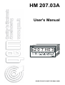
HM 207.03A
User's Manual
M2
0 7 H0 3
DOUBLE PULSE COUNT FOR SMAL SAWS
HM 207.03A
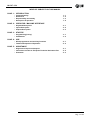
INDEX OF SUBJECTS IN THIS MANUAL
CHAP. 1 - INTRODUCTION
-
Complementarity
References
Responsibility and validity
Description of operation
1-1
1-2
1-3
1-4
CHAP. 2 - OPERATOR / MACHINE INTERFACE
- Keyboard Description
- Inputs Description
- Outputs Description
2-1
2-2
2-3
CHAP. 3 - STARTUP
- Programming (set-up)
- Calibrations
3-1
3-2
CHAP. 4 - USE
- Work programmes and auxiliary functions
- Tables and Graphics of Operation
4-1
4-2
CHAP. 5 - ASSISTANCE
- Diagnostic of inputs and outputs
- Instructions on How to Fill Up the Technical Assistance Fax
- Guarantee
5-1
5-2
5-3
Pag. 2 of 24
HM 207.03A
CHAPTER 1
INTRODUCTION
1 - 1 COMPLEMENTARITY
This manual is to be considered as a complement to the "Manual of installation, maintenance and assistance" which
supplies the indications for the performance of wirings, troubleshooting, procedures for startup and maintenance. This
manual contains indications for the instrument's use and for a correct programming.
We recommend therefore a careful reading and, in case of misunderstandings, please contact QEM for any further
explanation, by sending the Assistance Fax which you find enclosed to the manual.
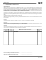
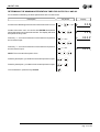
1 - 2 REFERENCES
The documentation concerning the instruments which are designed and sold by QEM has been divided into various
sheets in order to allow an effective and quick reading according to the information being seeked.
User's Manual
Hardware Structure
Manual of installation,
maintenance and assistance
Explanation of the software
described
Basic information concerning the
hardware of the series and possibility of customizations.
All what you need for Installation,
Maintenance and Assistance.
It is the present manual, which shows
all instructions for the comprehension and the use of the instrument
described. It is a manual concerning
the instrument's software; it shows
all instructions for the comprehension, programming, calibrations and
use of the instrument described.
Once you install the instrument by
following the instructions shown on
the Manual of Installation, maintenance and assistance, with this User's Manual you are supplied with all
necessary instructions for the correct use of the instrument and for its
programming.
It is a sheet enclosed to this User's
manual, describing the hardware
configuration concerning the series
of the instrument described.
It also shows the electrical, technical
and mechanical characteristics, of
the series and also the possible hardware customizations according to the
software version.
Further explanation of all necessary
subjects for a correct installation and
maintenance.
This is made to allow us to supply
valid and safe instructions which shall
allow you to perform products with a
recognized quality and safe reliability. It is also a valid support for all
those who must face a technical assistance on an application which includes a QEM's instrument.
Pag. 3 of 24
HM 207.03A
1 - 3 RESPONSIBILITY AND VALIDITY
RESPONSIBILITY
QEM is free from any responsibility for damages to people or things due to unobservance of the instructions and
prescriptions contained in this manual and in the "Manual of installation, maintenance and assistance". We also state
that the customer/purchaser must use the instrument according to the instructions supplied by QEM and in case of
doubt he must send a written application to QEM. Any authorization for further use and replacement shall be deemed
as valid by QEM, in case of contestation, only if it has been written by QEM.
No reprinting or republishing or delivery to third parties of this manual or of its parts is authorized unless a written
authorization is provided by QEM. Any infraction shall provoke a request of indemnization for damages on behalf of
QEM.
All rights generated by patents or models are reserved.
QEM reserves the right to partially or integrally modify the characteristics of the instrument described and the enclosed
documentation
Purpose
The purpose of this manual is to indicate the general rules to use the instrument described.
Indication
Write down and carefully store all parameters concerning the settings and programming of the instrument in order
to make easier the eventual operations of replacement and assistance.
VALIDITY
This manual can be applied to all designed instruments, built and tested by QEM and having the same ordering code.
This document is integrally valid except for mistakes or omissions.
Instrument's
Release
Manual
Release
2
0
Modifications made to the Manual
New manual
Modifications
Date
23 / 04 / 04
Emesso dal Responsabile Documentazione:
........................................................
Approvato dal Responsabile di Prodotto:
........................................................
Pag. 4 of 24
HM 207.03A
1 - 4 DESCRIPTION OF OPERATION
The instrument HM 207.03A displays the speed of a system sending an ON/OFF reading signal of its own speed
(Fmin. 1 Hz, Fmax. 5 Khz). The speed that is read is compared with the preset set-point and the increase or decrease
outputs are activated fto adjust the system's speed. The instrument availables by the RS232 serial port for PC
comincation (option).
Pag. 5 of 24
HM 207.03A
CHAPTER 2
OPERATOR/MACHINE INTERFACE
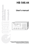
2 - 1 KEYBOARD DESCRIPTION
Key
Function
Normal operation: pressed for one second gives access to work speed programming.
Data input: confirms data imput.
Normal operation:pressed during normal functions, it displays the input and output status.
Data input:resets to zero the displayed data.
Normal operation:It increases the set-point in impulse or continuous mode.
Data input:Impulse or continuouse increase of the figures selected on the display (the
one that flashes).
Normal operation: decreases the set-point in impulse or continuous mode.
Data imput: it shifts to the right the digit selection on the display.
This is on while you are programming the set-up parameters.
Lighted while programming the work speed.
Lighted when reaching the Vmax. reading or during the adjustment phase.
Lighted when reaching the Vmin. reading.
Lighted while programming the speed table.
+
Access to the functions protected by password.
+
Access to the fselection speed table.
Pag. 6 of 24
HM 207.03A
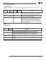
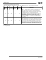
2 - 2 INPUTS DESCRIPTION
Inputs characteristics
Please refer to the chapter "Electrical characteristics" of the software leaflet "Hardware structure" enclosed to this
manual
Logical Activation Polarization
Terminal
Name status of
bloach
mode
terminal
activation
Description
4
I1
ON
C
3
RUN / WAIT. With input I1=ON speed adjustment is
enabled. If input I1=OFF the instrument is regulated by the
preset data; a variation in preset will give start to a new run.
5
I2
ON
I
3
CLOCK. Input signal for reading system speed (encoder or
proximity signal); max frequency 5 Khz.
3
TICK. Its functions are enabled with the presence of
inputs/outputs expansion (E). With input I5=ON it is the
synchronism signal for a speed transmission code (SETPOINT) with TE=2. With TE=1 it becomes the weight 22 in
the choice of speed table in binary code. Its activation time
must be more than 50 ms.
6
I4
ON
I
Legend
I = Impulsive input
C = Continuous input
Name
Terminal
bloach
+
1
Positive of transducers' power supply. Positive of voltage supplied by the
instrument for the supply of the instruments' inputs and of the transducers
-
2
Negative of transducers' power supply. Negative of voltage supplied by the
instrument for the supply of the instruments' inputs and of the transducers.
Vac
11
Voltage of instrument's power supply. Alternated voltage according to the code of
your order.
Vac
12
Voltage of instrument's power supply. Alternated voltage according to the code of
your order.
GND
13
Ground Connection. We recommend a conductor with Ø 4 mm.
Description
Pag. 7 of 24
HM 207.03A
Inputs expansion characteristics (option E)
Refer to the “Electrical characteristics” chapter of the “Hardware structure” file enclosed to this manual.
Logical Activation Polarization
Terminal
Name status of
bloach
mode
terminal
activation
15
16
I5
I6
ON
ON
P
P
Description
14
ABL / +. Enabled, when in SET-UP the parameter TE=2,
this is the enabling command for reading transmission
speed (SET-POINT). The signal must remain active during
the whole transmission; if de-activated during the
transmission it aborts the transmission itself. If in SET-UP
the parameter TE=0 this is the command for acceleration
with functions programmed in SET-UP. With TE=1 it
becomes the weight 21 in choosing the speed table with
binary code.
14
DATA / -. Enabled, when in SET-UP the parameter TE=2,
this is the signal that in synchronism with input I4 receives
the numerical speed value (SET-POINT). The data is read if
input I5=1 and when input I4 is activated. If in SET-UP the
parameter TE=0 it is the command for deceleration with the
functions programmed in SET-UP. With TE=1 it becomes
weight 20 in the choosing the speed table with binary code.
Legend
P = Programmable
Pag. 8 of 24
HM 207.03A
2 - 3 OUTPUTS
Characteristics of outputs
Please refer to the chapter "Electrical Characteristics" of the leaflet "Hardware structure" enclosed to this manual.
Terminal
bloach
Name
Logical
status of
activation
Polarization
terminal
Activation
mode
9
U1
ON
P
8
INCREASE. Increases the system speed. Its
duration is proportional to the speed error.
10
U2
ON
P
8
DECREASE. Decreases the system speed. Its
duration is proportional to the speed error .
Description
Legend
P = Programmable
Outputs expansion characteristics (option E)
Refer to the “Electrical characteristics” chapter of the “Hardware structure” file enclosed to this manual.
Terminal
Name
bloach
18
U3
Logical Activation Polarization
status of
mode
terminal
activation
ON
C
Description
17
FAST. Activated when the error between set-point and real
speed is greater than the activation range of U3 (SET-UP).
19
U4
ON
C
17
MAXIMUM SPEED LIMIT / ADJUSTMENT RANGE. Set
as a speed limit, it remains active until the speed read by
the instrument is equal or superior to the maximum limit set
in SET-UP. Set as a range of adjustment (only with the
parameter "Programming output U4"=0 in SET-UP), it is
activated when the error between the set-point and ral
speed is less than the percentage set in parameter FI.
20
U5
ON
C
17
MINIMUM SPEED LIMIT. Activated when the speed read
by the instrument is equal or inferior to the minimum limit
set in SET-UP.
Legend
C = Countinuos signal
RS232 serial port expansion characteristics (option RS)
Refer to the “Electrical characteristics” chapter of the “Hardware structure” file enclosed to this manual.
Terminal
Name
bloach
24
Description
GND Common of connection serial port
25
RX
Input of reception instrument
26
TX
Output of tramission instrument
Pag. 9 of 24
HM 207.03A
CHAPTER 3
SETTING FOR OPERATION
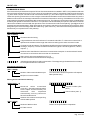
3 - 1 PROGRAMMING (SET-UP)
As these parameters set the operating mode of the instrument, access is restricted to the installer only. A password
must be entered to access the programming, with the following procedure:
Description
Keyboard
Access to the set-up programming.
+
Enter the access code "207" and confirm with ENTER.
Disables speed adjustment and outputs U1, U2.
Display
000
H
= ON
(On completion of the data input for each function, press ENTER to confirm and proceed to the next step.)
FUNCTION
DISPLAY
DESCRIPTION
C
0
F
400000
n
99999
Minimum speed
u
99999
Reading
averages
i
99
A
r 99999
Decimal digits
Maximum
frequency
Maximum speed
Minimum speed
limit for automatic
adjustment
0 = Maximum display
1 = Maximum display
2 = Maximum display
3 = Maximum display
999999
99999,9
9999,99
999,999
This indicates the value that the instrument displays at maximum
frequency. (Chaper "Setting the Tachometer").
Indicates the value that the instrument displays at maximum
frequency. It is the maxmum threshold of speed above which U4 is
activated. It is the maximum programmable speed. To exploit the
resolution of the system, enter the maximum speed value
reachable in real work conditions.
The minimum speed threshold over which output U5 is activated.
This is the minimum programmable speed
This indicates every how many readings the speed to display
(Calibration) is calculated. The higher the number of readings, the
slower the speed updating time.
= 0 adjustment is always enabled in automatic.
>0
adjustment is enabled only if the speed detected in input
exceeds this value.
In mechanical adjusters this parameter is stated by the
manufacturer to avoid mechanical breakages in the system
Minimum time of
activation for
outputs U1
t
I
99
This is the time, expressed in milliseconds for activating output U1
within which the system does not undergo any change in speed.
Each unit is equal to 5 ms.
Minimum time of
activation for
outputs U2
t
2
99
This is the time, expressed in milliseconds for activating output U2
within which the system does not undergo any change in speed.
Each unit is equal to 5 ms.
System reply time
t
r
999
This is the time, expressed in milliseconds, in which the system,
starting from zero speed, reaches the maximum speed consented
with the increase command (U1) always active.
Pag. 10 of 24
HM 207.03A
FUNCTION
DISPLAY
DESCRIPTION
U
3
0000
t
E
0
Output U3 range
of activation
This parameter is to be programmed when the instrument is
provided with input/output expansion (order code E). It determines
the activation range of output U3. The error speed is compared
with the programmed value. If the error is > the activation range,
output U3 is activated and used to increase the speed variations
(greater oil flow). If the value introduced is less than the current
range, the instrument adjusts output U3 according to the range
determined by the current band (gain)
This parameter is programmed when the instrument is provided
with input/output expansion (order code E).
0 = The programmed speed can be modified from inputs I5 and I6.
The first variation of speed occurs after 750 ms.
Transmission
set-point with
expansion
1 = With inputs I4, I5, I6 it is possible to set a speed programmed
in the instrument table (values from 1 to 7).
5 = With inputs I4, I5, I6 it is possible to set a speed with a value
transmitted from an external unit (PLC).
Type of variation
from input I5 or I6
or frome keys + -
0
H
0 = The variation of the system's speed set-point is in continuous
mode.
1 = The variation of the system's speed set-point is in impulse
mode.
Hysteresis time
outputs U4, U5
t
i
999
Programming
output U4
U
4
0
It is the minimum time, expressed in seconds, for activating or deactivating outputs U1 and U2 in comparison to the system speed
0 = The output functins as a maximum speed limi.
1 = The output functions as a sensor for the adjustment range
If parameter "Program output U4"=1 is present, this display will also be shown
Adjustment
range
RS-232C
enabled
F
i
999
r
5
0
Indicates the percentage (+, -) of eror between the set-point and
the real speed. If the error is negative, output U4 is activated.
0 = RS-232C transmission disabled. The option is not used for RS
232C transmission (order code RS).
1 = RS-232C transmission enabled.
If parameter " RS-232Cenabled"=1 is present, these displays will be shown
b
Transmission
speed RS-232-C
r
4800
110 baud
150 baud
300 baud
600 baud
1200 baud
2400 baud
4800 baud
9600 baud
Transmission speeds available;
if the speed is incorrect the
default takes the value of 9600
Pag. 11 of 24
HM 207.03A
FUNCTION
DISPLAY
Number of
data bits
d
Number of
stop bits
S
Address
code
c
b
DESCRIPTION
7
7 stop bit
8 stop bits
Number of bits available; if the number of bits is incorrect the
default takes the value of 8
b
2
1 stop bit
2 stop bits
Number of stop bits available; if the number of bits is incorrect, the
default takes the value of 2
I
00
This is the code to be assigned to the unit whenw ishing to connect
the instrument to others in a DAISY-CHAIN arrangement. If the
address is reset to zero, every command will be obeyed and it is
not necessary to send the address code
After programming the last function the screen will return to the display in use before
entering SET-UPand the PRG led goes out
Pag. 12 of 24
HM 207.03A
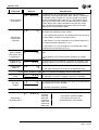
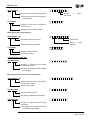
3 - 2 SETTING
SETTING THE TACHOMETER
To facilitate the installation and the inputting of the SET-UP values that establish how the speed is displayed, you can
display the frequency meter (Hz) and the total count of the clock pulses by proceeding as follows:
Description
Access to setting the tachometer.
Input the value "456". On confirms with ENTER this disables speed
adjustment and outputs U1and U2; the frequencymeter is displayed. This value is then input in SET-UP in the parameter
“Maximum frequency”.
Keyboard
+
× 1 sec.
Display
H
000
F
123
C
123456
Every 2 second display the clock pulse (the count is zeroed every
time you access the tachometer setting mode).
To exit press the key CLEAR.
To obtain a correct display it is essential to define the maximum frequency, maximum frequency display and duty cycle
parameters. To establish the maximum frequency (pulses per second) that the transducer transmits, simply bring the
transducer up to maximum speed and, in tachometer setting mode, (-) + (ENTER) + (Password 456), read the
frequency that the instrument displays. This value is then input in SET-UP in the parameter “Maximum frequency”.
This is the frequency at which the value you want to display is calculated. You consequently have to establish the value
of each clock pulse in engineering units. Said figure may be already known to the installer, or it can be calculated by
experiment; to do so, access the tachometer setting mode again, make the system turn so that the actuator elements
are moved to a measurement known to the installer (e.g. 1 m, 10 m, 100 mm, etc.) and make a record of the number
of clock pulses read by the instrument.
No. of measurements = F. max. / No. pulses read
Max. display = No. of measurements x Known measurement
The value of the max. display calculated as above is input in the corresponding SET-UP parameter, adapting it to the
time unit adopted.
N.B. The calculated value must be adapted to the number of decimal figures that you want to display.
E.g. F. max. = 1638.4 Hz
At 100 mm, the count acquired equates to 200 pulses, so 1638.4 ¸ 200 = 8.192 (No. of measurements per second).
In the interval of one second the system covers 8.192 x 100 = 819.2 mm.
The value to input in SET-UP for maximum display can be converted into:
mm/minute = 49152
m/second = 0.8192
m/minute = 49.152
N.B. If the system is moving at a rate of 0.2 m/second (real speed), the input frequency will be:
(F. max. / Vis. max.) x V. reale=(1638,4 / 0,8192) x 0,2=400 Hz
Pag. 13 of 24
HM 207.03A
CALIBRATING THE ADJUSTMENT PARAMETERS
Description
Acess to the calibrating the adjustment parameters.
Introduce the code "123". On confirm with ENTER, the display will
show the number of readings to use in calculating the system
speed used for speed regulation.
Keyboard
+
× 1 sec.
Display
000
H
L
r
99
Introduce the number of read. The higher the value introduced and
the slower the speed update time will be. On confirm with ENTER,
the display will show increment of instrument is in PID adjustment.
G
A
0000
Introduce the gain value.The value introduced is the error multiplication factor. On confirm with ENTER, the display will show the
overall time.
t
i
999
Introduce the overall time (expressed in seconds).On confirm with
ENTER, the display will show the time of derived time.
t
d
999
b
n
999
Introduce the derived time (expressed in seconds). On confirm with
ENTER, the display will show the dead centring band.
Introduce the dead centring band (expressed as a percentage of
the adjustment output value max. 200%).On confirming with ENTER, the screen returns to showing the displays currently in use.
Pag. 14 of 24
HM 207.03A
DETERMINING THE MINIMUM INTERVENTION TIMES FOR OUTPUTS U1 AND U2
For sounddess calibrating,the base speed will be at the central strais.
Description
Access to the calibrating of the minimun intervention time U1 e U2.
Display
Keyboard
+
Introduce the code "100". On confirm with ENTER this disables
speed adjustment and outputs U1and U2. The display will show
the speed currently read.
× 1 sec.
H
000
F
123
Press key "+", to access introduction of the ON time required for
the increase output.
× 1 sec.
A
0001
Press key "+", to access introduction of the ON time required for
the decrement output.
× 1 sec.
d
0001
NOTE: The unit entered is equal to 5 ms.
Press key description,you obtain the decrease impulse in output.
+
Press key description, you obtain the increase impulse in output.
+
To exit calibration, press the key CLEAR .
Pag. 15 of 24
HM 207.03A
CHAPTER 4
USE
4 - 1 WORK PROGRAMMES AND AUXILIARY FUNCTIONS
INTRODUCING MINIMUM AND MAXIMUM TARGHETS POSITIONS
Description
Access the function for the work speed. On confirming with ENTER
the display shows the work speed.
Keyboard
× 1 sec.
Display
P
12345
= ON
= OFF
N.B.The work speed can be varied with keys + and - or with inputs
I4 or I5 (input/output expansion) when not in the programming
phase. In normal functions, by pressing the key + or - the instrument
displays the work speed set-point that varies. During normal
functions the instrument displays the detected speed (tachometer)
PROGRAMMING THE SPEED TABLE
Description
Keyboard
+
Access the speed table.
× 1 sec.
Display
000
H
= ON
Introduce thecode "789". On confirm with ENTER this disables
speed adjustment and outputs U1and U2, and display will sow the
first speed in the table (max.7).
Program the first speed in the table. On confirm with ENTER, the
display shows the second speed table (max.7).
Program the first speed in the table. On confirm with ENTER, the
display shows 3th speed in the table and so up to the 7th speed in
the table.
I
12345
2
378
3
721
On confirming with ENTER the 7th speed in the table, the Set led
goes out and the screen returns to the displays currently in use.
= OFF
CHOOSING THE SPEED FROM THE TABLE
Description
Access the chose the speed from the table.
Keyboard
+
Display
1
12345
Choose the work speed, selecting the number that corresponds
with the programmed table (max. 7). On confirming with ENTER,
the speed will be executed immediately and the screen will return
to the displays currently in use.
Pag. 16 of 24
HM 207.03A
DISPLAYING
Description
Speed read.
Keyboard
Display
123456
Pag. 17 of 24
HM 207.03A
COMMANDS IN RS232
If the instrument is provided with the option RS 232-C and transmission is enabled in SET-U, it is possible to transmit
write and read commands from a PC. Every string of comands sent to the PC must always start from the character
"{" ( ascii value=123) for command code or from the character "(" ( ascii value=40) for numerical series. The first 2
characters opening transmission or of the single commands transmitted must be numerical because they are the
address code to which the message is destined or fromwhich information is arriving. If the address "00" is sent, this
means that the information is destined to all the instruments on line. The following 2 characters must be 2 capital letters
to identify the operative code of the instruction. The operative code is followed by the operand, that is the numerical
value of the variable concerned with the operative code. Characters sent without first placing "{"and @ at the end
generally are retransmitted as an "ECO" effect but do not cause any reaction by the instrument receiving them. Each
string sent by the instrument begins with the character "[" (ascii value=91). The instrument is always a slave and can
transmit only on request from the PC (master).
Main command syntax:
{ XX YY XXX @
Character at end of string
3-figure address with the first letter of command code=M or T. It becomes a numerical or
alphanumerical datum with a length that varies according to the other command codes
Command code (two letters). The first letter identifies the type of data to be transmitted (table,
message, set-point). The second letter identifies the type of command (aperture, closure,
request ...)
Address code. Identifies the instrument in transmission/reception. It can be omitted if serial
connection is not foreseen with more than one instrument
Start code for string transmitted from PC ({, ()
The first character in the transmission string is "["
Indica tes the stringa to be used in transmission. The empty string indicates that the command
is not implemented in the instrument
Command code letter "T":
{ XX TY XXX @
{ 0 1 T A 0 0 1 @
Number of the numerical table to open
A=Open a numerical table
The command T allows composition of thespeed
table (number 001)
Writing in the instrument's memory:
( XXX XXXXX ... @
( 0 0 1 1 2 3 . 5 @
Numerical
series
transmitted
(1234,55..). Several numerical values
are accepted and identified by the
instrument
then
separated
automatically, so every value must
have a fixed dimension
Register number (Setpoint)
Value number (max. 7)
Address of the datum corresponding
with the table opened
{ XX TY XXX @
{ 0 1 T C 0 0 1 @
Number of table to close
Closure of the speed table composition
C=Table closure
Pag. 18 of 24
HM 207.03A
{ XX TY XXX @
{ 0 1 T ? 0 0 1 @
Number
requested
Number of numerical table requested
?=Request from PC to instrument to
read the table
[ TY XXX @
of
table
[ T A 0 0 1 @
Number of the numerical table to
transmit to PC
A=Opening of a numerical table
Writing operation in PC memory:
[ XXX XXXXX ... @
[ 0 0 1 2 3 4 . 5 @
Value transmitted (1234,55..)
Speed value
Address of table transmitted
Speed
address
[ TY XXX @
value
[ T C 0 0 1 @
Number of table to close
C=Closing of table
Command code letter "M":
{ XX MY XXX @
Number of alphanumerical table
(messages) to open
A=Opening of an alphanumerical table
(messages)
Writing operations in the instrument memory:
( XXX XXXXX ... @
Alphanumerical code transmitted
(ALUF and C 67 AS ...)
Address of the table
{ XX MY XXX @
Number of table to close
C=Closing of alphanumerical table
{ XX MY XXX @
Number of alphanumerical table
requested
?=Request by PC to instrument to read
the alphanumerical table
Pag. 19 of 24
HM 207.03A
[ MY XXX @
Number of alphanumerical table to
transmit to PC
A=Opening of an alphanumerical table
Writing operations in PC memory:
[ XXX XXXXX ... @
Alphanumerical code transmitted
(CRS IDEA 1 ...)
Address of the alphanumerical table
transmitted
[ MY XXX @
Number of the table to close
C=Closing table transmission
Command code letter "S":
Writing operations in instrument memory:
{ XX SY XXX ... @
{ 0 1 S V 1 2 3 . 5 @
Numerical
series
transmitted
(123,5345,7)
V=Successive characters are not an
address but a series of numbers. The
letter (any) identifies the variable
transmitted
{ XX SY @
Value of set-point
Speed
write
command code
{ 0 1 S ? @
?=Request from PC to instrument to
read the numerical series. The
instrument will transmit all the
variables
Write operations in PC memory:
[ Y XXXXX ... @
Request for transmission of the variables present
in the instrument (set-point and speed)
[ S 1 2 3 . 5 @
Numerical
series transmitted
(123,5345,7). Max. 32 characters
Value transmitted( set-point
or processor variable)
V=
The letter identifies the variable
transmitted
S= Set-point
U=Speed
variable)
(processor
Pag. 20 of 24
HM 207.03A
Command code letter"P":
Writing operations in the instrument memory:
{ XX PY XXX ... @
Alphanumerical series transmitted
(ABC,5*ER9,7). Max. 32 characters
V=The successive characters are not
an address but an alphanumerical
series
{ XX PY @
?=Request by PC to instrument to read
the alphanumerical series
Writing operation in PC memory:
[ XXXXX ... @
Alphanumerical series transmitted by
the instrument. Max. 32 characters
Command code letter "C":
Used in the on-line commands
{ XX CY XXX @
{ 0 1 C T V 0 3 @
Number of command code composed
of one letter followed by two numbers
E=The successive characters are not
an address but a letter followed by two
numbers
Speed table address
The table value (set-point) transmitted
is executed and recalled with the
transmitted address
Pag. 21 of 24
HM 207.03A
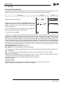
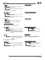
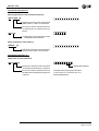
4 - 2 OPERATION GRAPHS AND TABLES
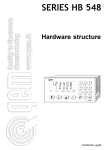
DIAGRAMMA TRASMISSIONE VELOCITÀ CON TE=2
I5=Abl
20 21 22 23 20 21 22 23 20 21 22 23 20 21 22 23 20 21 22 23
I6=Datum
I4=Tick
50 ms.
Value transmitted
8 tens
6 hundreds
5 units
1 tens of
7
thousands thousands
Speed value transmitted=17685
Minimum speed transmission time=2 seconds
Minimum transmission time of table number=0,4 seconds
The transmission of speed or the table to the instrument can be made when input and output expansion is present
(order code E).
To acquire the data, transmission must be made in succession of the presence or otherwise of the weight of the single
bit, starting from the least significant number.
When transmitting the speed, all five numbers of the value must be transmitted
N.B. If input ABL is de-activated, the data and the tick will be ignored
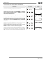
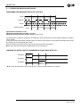
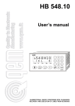
DIAGRAM OF SPEED CHOICE TRANSMISSION FROM TABLE WITH TE=1
I6=weight 2 0
50 ms.
I5=weight 2 1
I4=weight 2 2
Speed
selection 3
Speed
selection 4
N.B. It must have a duration of more than 50 ms. for the transmitted data to be accepted.
Pag. 22 of 24
HM 207.03A
CHAPTER 5
ASSISTANCE
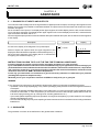
5 - 1 DIAGNOSTIC OF INPUTS AND OUTPUTS
The instrument offers a diagnostic of the logical status of digital inputs and outputs; according to the segments of the
display which are ON, it is possible to understand whether an input arrives to the instrument and whether the output
has been energised.
As for the status of the inputs, if it is displayed the upper segment of the first display from the left, it means that the
input 1 has been activated; if it is displayed the upper segment of the second display from the left, it means that the
input 2 has been activated, and so on.
As for the digital outputs, please consider as valid the description made for the inputs, but consider the lower segments
of the display
Description
Access to the display of the diagnostic for inputs/outputs.
Keyboard
Display
X 2 sec.
Status of inputs and outputs. When the upper segments of the
display are ON it indicates the adquisition of the related inputs ("^").
When the lower segments of the display are On it indicates the
energising of the related outputs ("_").
I1 I2 I3 I4
o
~~^ ^
U1 U2
INSTRUCTIONS ON HOW TO FILL UP THE FAX FOR TECHNICAL ASSISTANCE
In order to be able to provide a quick, specific and quality assistance, we need your help.
If you need QEM's assistance to face the eventual troubleshooting in your applications and even though you
performed all instructions indicated in the manual of "Installation, maintenance and assistance", the problem
still continues, please fill up every blank of the fax enclosed to the manual of Installation, maintenance and
assistance and send it to QEM's Assistance Department.
In this way you shall allow our technicians to get the necessary elements to understand your problem
(avoiding thus expensive telephone calls).
We thank you for your cooperation and here at QEM's we really wish you a good job.
REMARK
If you must send an instrument to be repaired, please strictly follow our instructions indicated here below:
- If possible, use the original packaging; in any case the packaging must protect the instrument against shocks due
to transport.
- Insert into the package a detailed description of the malfunction you found and the part of wiring diagram which
includes the instrument. In case the problem you discovered concerns data storage, please also include the
instrument's programming (set-up, working levels, auxiliary parameters, etc.).
- If you need it, please explicitely require the quotation of charges for the repairing: if you do not ask for it, the charges
shall be calculated as a whole.
- Our technicians shall give priority to the repairing of those instruments which have been sent according to the items
listed above.
5 - 3 GUARANTEE
The guarantee is conform to the definitions of the general sales conditions.
Pag. 23 of 24
HM 207.03A
NOTE
This product is an electronic instrument and, therefore, should not be considered a machine. As a consequence,
it is not subject to the requirements of EEC Directive 89/392 (Machine Directive). For this reason, we affirm that if
the QEM instrument is used as a component of a machine, it may not be turned on if the machine does not satisfy
the requirements of the Machine Directive.
The instruments marking does not relieve the customer from fulfilling the obligations of the law relative to the
finished product.
Pag. 24 of 24