1
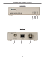
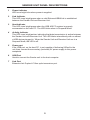
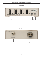
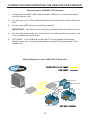
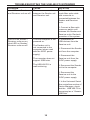
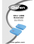
®
USB 400 FO
EXT-USB-400FON
User Manual
www.gefen.com
ASKING FOR ASSISTANCE
Technical Support:
Telephone
(818) 772-9100
(800) 545-6900
Fax(818) 772-9120
Technical Support Hours:
8:00 AM to 5:00 PM PST Monday through Friday, Pacific Time
Write To:
Gefen, LLC
c/o Customer Service
20600 Nordhoff St
Chatsworth, CA 91311
www.gefen.com
[email protected]
Notice
Gefen, LLC reserves the right to make changes in the hardware, packaging, and
any accompanying documentation without prior written notice.
USB 400 FO is a trademark of Gefen, LLC
All trademarks are the property of their respective owners.
© 2011 Gefen, LLC. All rights reserved.
All trademarks are the property of their respective companies.
Rev A7
CONTENTS
1
Introduction
2
Operation Notes
3
Features
4
Sender Unit Panel Layout
5
Sender Unit Panel Descriptions
6
Receiver Unit Panel Layout
7
Receiver Unit Panel Descriptions
8
Connecting And Operating The USB 400 FO Extender
8
Wiring Diagram
9
Troubleshooting The USB 400FO Extender
14 Specifications
15 Warranty
INTRODUCTION
Congratulations on your purchase of the USB 400 FO. Your complete satisfaction
is very important to us.
Gefen
Gefen delivers innovative, progressive computer and electronics add-on solutions
that harness integration, extension, distribution and conversion technologies.
Gefen’s reliable, plug-and-play products supplement cross-platform computer
systems, professional audio/video environments, and HDTV systems of all sizes
with hard-working solutions that are easy to implement and simple to operate.
The Gefen USB 400 FO
The USB 400 FO Extender supports all USB 2.0 devices, extending to 1640 feet
(500 meters) away from the USB source using 50/125µm multi-mode fiber, or
900 feet (275 meters) using a 62.5/125 µm multi-mode fiber. The receiver end is
also a four USB 2.0 hub.
By using fiber optic cables, the USB 400 FO extends a long distance from the
location of a computer. It provides an EMI-free solution for using USB at remote
locations.
How It Works
The USB 400 FO sender unit is connected to the source using the supplied USB
short cable. The USB peripheral(s) are connected to the receiver unit at the
remote end. Two LC-terminated multi-mode fiber optic cables are used to link the
sender to the receiver. The Receiver unit must be powered by a 5V DC power
supply. The Sender unit is powered by the USB bus.
Applications
The USB 400 FO is invaluable for applications where complete control of devices
is necessary when using USB when placing in restricted areas, such as medical
facilities and oil rigs. The USB 400 FO will connect with any USB-compliant
peripheral in all operating systems supporting USB 2.0.
1
OPERATION NOTES
READ THESE NOTES BEFORE INSTALLING OR
OPERATING THE USB 400 FO
This equipment provides outstanding extension facilities for any device or USB
application that requires a peripheral connection over a distance, such as a USB
camera or USB hard drive, keyboard, and mouse.
The USB 400 FO works like a USB hub with extension capabilities over a distance
of up to 1,640 feet. This means, for example, that a remote USB sensor can be
placed at a safe distance from the sender unit in situations that demand this type
of security.
The USB 400 FO signal controls the keyboard, mouse, trackball, and other USB
peripherals using send and receive units. The USB signal is extended by using
multi-mode fiber optic cabling.
The USB 400 FO uses dual multi-mode LC fiber optic cables to connect the sender
and receiver units.
FCC Radio Frequency Interference Statement Warning
This device complies with Part 15 of the FCC rules. Operation is subject to the
following two conditions:
(1) this device may not cause harmful interference, and (2) this device must
accept any interference received including interference that may cause undesired
operation.
Requirements:
To complete the installation, you will also require the following items that are not
included with the product:
•
USB 1.1 or 2.0 Compatible computer (host computer) with a USB compliant
operating system
•
USB 1.1 or 2.0 Compatible device
•
2-strand multi-mode fiber optic cable with Duplex LC connectors (if using
surface cabling) OR, 2-strand fiber optic cabling with two information outlets
and two 2-strand fiber optic patch cords with Duplex LC connectors (if using
premise cabling) .
The Sender Unit and Receiver Unit are interconnected by up to 500 meters of
fiber optic cabling. Two strands of 50/125μm (1640 feet max.) multi-mode fiber or
62.5/125μm (900 feet max.) multi-mode fiber cabling are required. The cabling
subsystem must provide a duplex connection with crossover, and must be
terminated with Duplex LC connectors at both ends.
2
FEATURES
Features
•
“Extreme USB” technology is used to extend the range of USB 2.0 devices
up to 1640 feet (500 meters) using 50/125μm fiber-optic cables
•
Receiver unit is also a USB 2.0 four-port hub
•
Provides support for both low-speed and high-speed USB devices
•
Fully backward-compliant with USB 1.1 and USB 2.0 specifications as
certified by the USB Implementation.
•
Number of USB devices can be expanded using standard USB hubs
•
Supports all operating systems including Windows®, Mac OS®, and Linux®
•
Supports other USB peripherals and are used in devices such as PlayStation
and Wii.
•
A secure method of USB control in areas where environmental conditions
prohibit access by people
•
Metal box for better RF shielding
•
Ideal as optical isolation from over-voltage and static electricity
•
Supports High Speed devices up to 480Mbps
Package Includes
(1) Gefen USB-400FO Sender Unit
(1) Gefen USB-400FO Receiver Unit
(1) 6 ft. USB Cable (A-B)
(2) 5V DC Power Supplies
(1) Quick-Start Guide
3
SENDER UNIT PANEL LAYOUT
Front Panel
1 2
Back Panel
5
6
7
4
3 4
SENDER UNIT PANEL DESCRIPTIONS
1
Power Indicator
LED turns bright blue when power is supplied.
2
Link Indicator
This LED turns bright green when a valid ExtremeUSB® link is established
between the Sender Unit and Receiver Unit.
3
Host Indicator
This LED turns bright green when the USB 400 FO system is properly
enumerated on the host PC. The LED blinks when in Suspend Mode.
4
Activity Indicator
This LED turns bright amber, indicating that data transmission is active between
the Sender Unit and Receiver Unit. The LED blinks intermittently with or without
a USB device plugged in. When the Sender Unit and Receiver Unit are in a
Suspend Mode, the LED is off.
5
Power port
If the USB port, on the host PC, is not capable of delivering 500mA to the
unit, then connect the secondary (included) 5V power supply to this power
receptacle.
6
USB Port
Used to connect the Sender unit to the host computer.
7
Link Port
Extension link Duplex LC fiber optic transceiver port.
5
RECEIVER UNIT PANEL LAYOUT
Front Panel
1
2
3 4 5 6
Back Panel
7
8
6
RECEIVER UNIT PANEL DESCRIPTIONS
1
USB Port (1-4)
USB device input ports.
2
USB Indicator (1-4)
This LED indicates when a USB device is connected to the Device Port. Solid
green when device is plugged in and active. Off when device is in a suspend
mode or Receiver unit is powered off. Orange when the Receiver unit detects an
overcurrent condition, or if the attached USB device attempts to draw more than
the 500mA current.
3
Power Indicator
This LED turns bright blue when power is supplied.
4
Link Indicator
This LED turns bright green when a valid ExtremeUSB® link is established
between the Sender Unit and Receiver Unit.
5
Host Indicator
This LED turns bright green when the USB 400 FO system is properly
enumerated on the host PC. The LED blinks when in Suspend Mode.
6
Activity Indicator
This LED turns bright amber, indicating that data transmission is active between
the Sender and Receiver. The LED blinks intermittently with or without a USB
device plugged in. When the Sender Unit and Receiver Unit are in a Suspend
Mode, the LED is off.
7
Power port
Connects to the 5V DC power supply.
8
Link Port
Connect one end of a duplex LC fiber optic cable to this port.
7
CONNECTING AND OPERATING THE USB-400FON EXTENDER
Connecting the USB 400 FO Extender
1. Connect the included USB cable between USB port on the host computer
and the Sender Unit.
2. Connect two (2) LC-fiber cables between the Sender Unit and the Receiver
Unit.
3. Connect the USB devices to the Receiver Unit.
IMPORTANT: The Sender Unit must be powered before the Receiver Unit.
4. Connect the power supply to the Receiver Unit and connect the power cord
to an available electrical outlet.
5. OPTIONAL: If the USB port on the host PC is not capable of delivering
500mA to the unit, connect the secondary (included) 5V power supply to the
Sender unit.
Wiring Diagram for the USB 400 FO Extender
FIBER OPTIC LC-LC CABLE
(Up to 1640 ft.)
USB CABLE
Receiver
USB Peripheral
USB Peripheral
Computer
Sender
USB Peripheral
USB Peripheral
8
EXT-USB-400FON
TROUBLESHOOTING
Verifying Installation on PC or Macintosh Computers
1. For Windows users (2000, XP, Vista, Windows 7), open the Device Manager
to confirm that the USB 400 FO has installed correctly. Expand the entry for
Universal Serial Bus controllers by clicking the + sign. If the USB 400 FO has
been installed correctly, you should find it listed as a “Generic USB Hub”.
2. For Mac OS X users, open the System Profiler to confirm that the
USB 400 FO has installed correctly. In the left hand column under Hardware,
select “USB” and inspect the right hand panel. If the USB 400 FO has been
installed correctly, you should find it listed as a “Hub” under the USB high-Speed
Bus/USB Bus.
The following table provides additional troubleshooting tips. The topics are
arranged in the order in which they should be executed in most situations. If
you are unable to resolve the problem after following these instructions, please
contact technical support for further assistance.
PROBLEM
CAUSE
SOLUTION
All LEDs on
Sender unit are
off.
The Sender unit is not
receiving power from the
USB port or the 5VDC
power supply.
1. Ensure that the USB
connection between the
Sender and host computer is
properly installed.
2. Move the USB connector to
another USB port on the host
computer.
All LEDs on
Receiver unit
are off.
The Receiver unit is not
receiving power from the
5VDC power supply.
1. Ensure that the 5VDC
power supply is properly
connected to the Receiver
unit.
2. Check that the 5VDC
power supply is connected
to a live source of electrical
power. Check that the
Receiver power LED is
illuminated.
9
TROUBLESHOOTING THE USB 400 FO EXTENDER
PROBLEM
CAUSE
SOLUTION
Link LEDs on Sender unit There is no connection
and Receiver unit are off. between the Sender unit
and Receiver unit.
1. Ensure that a multimode fiber optic cable
with crossover is
connected between the
Sender and Receiver
units.
2. Connect a fiber optic
crossover patch cord
between the Sender and
Receiver units. Recheck
operation of the system.
Link LED on Sender /
Receiver units are on,
Host LED on Sender/
Receiver units are off.
The host computer is not
powered on.
The Sender unit is
not connected to the
computer (when used
with the 5VDC power
supply).
The computer does not
support USB hubs.
The USB 400 FO is
malfunctioning.
1. Disconnect all
USB devices from the
Receiver unit.
2. Disconnect the Sender
unit from the computer.
3. Disconnect the
Receiver unit from the
5VDC power supply.
4. Reconnect the Sender
unit to the computer.
5. Reconnect the
Receiver unit to the
5VDC power supply.
6. In the Universal Serial
Bus controllers section of
Device Manager, check
that the USB 400 FO is
recognized as a “Generic
USB Hub”.
10
TROUBLESHOOTING THE USB 400 FO EXTENDER
PROBLEM
CAUSE
SOLUTION
USB 400 FO units were
working, but the Host
LED on Sender/Receiver
units are suddenly
blinking
The Receiver unit is
in suspend mode. The
operating system may
put the USB 400 FO in
suspend mode when
computer is put into
Suspend/Standby state
or when no USB devices
are attached.
1. Recover/Resume the
operating system from
Suspend/Standby mode
(see your operating
system’s documentation).
2. Attach a USB device to
the USB 400 FO.
All LEDs on both the
Sender unit and Receiver
unit are on but the USB
device does not operate
correctly, or is detected
as an “Unknown Device”
in the operating system.
The USB device is
malfunctioning.
1. Disconnect the
USB-400FO from the
computer.
2. Connect the USB
device directly to the USB
port on the computer.
3. If the device does not
operate properly, consult
the user documentation
for the device.
4. Update your system
BIOS, chipset, or USB
Host controller drivers
from your System/Mother
board manufacturer’s
website.
5. If device operates
properly when directly
connected to computer,
connect another device
to the USB 400 FO.
Connect the USB
400 FO to computer.
6. If the second device
does not operate, the
USB 400 FO may
be malfunctioning.
Contact Technical
Support for assistance.
7. If the second device
does operate properly,
the first device may not
be compatible with the
USB 400 FO.
The computer does
not recognize the USB
device.
The application software
for the device is not
operating.
11
TROUBLESHOOTING THE USB 400 FO EXTENDER
PROBLEM
CAUSE
SOLUTION
USB device
is attached to
Receiver USB
port but Receiver
device LED is off
A USB device must have
the appropriate driver
installed on the computer
operating system
1. Install the required
USB device driver on the
computer operating system
prior to attaching the USB
device to the Receiver unit.
Please see your USB device
manufacturer’s website for
details.
2. Consult your USB device
documentation and power
your USB device with the
additional, USB device
manufacturer supplied, power
supply (if available).
Device LED is
orange and units
are no longer
functioning.
Overcurrent condition has
occurred because USB
device draws more power
than can be supplied
per USB specification
(500mA).
1. Power-cycle Receiver.
LED Host and
LINK LEDs on
Sender/Receiver
units blink
intermittently.
Firmware mismatch
between the Sender and
Receiver.
1. Use a different Sender/
Receiver pair which have the
same firmware revision.
2. Upgrade the Sender/
Receiver firmware, contact
technical support for
assistance.
12
SPECIFICATIONS
USB Maximum Transfer Rate....................................................................480Mbps
USB Connector (Sender).........................................................................(1) Type B
USB Connector (Receiver) .....................................................................(4) Type A
Link Connector............................................................................(2) Fiber, Type LC
Power Supply (Sender / Receiver.).................................................5V DC, Locking
Operating temperature range....................................................................0 - 50 °C
Dimensions (Sender / Receiver)............................................4” W x 3” D x 1.25” H
Shipping Weight...............................................................................................2 lbs
Range.........................1640ft. (500m) over 50/125µm multi-mode fiber optic cable
900ft. (275m) over 62.5/125µm multi-mode fiber optic cable
13
WARRANTY
Gefen warrants the equipment it manufactures to be free from defects in material
and workmanship.
If equipment fails because of such defects and Gefen is notified within two (2)
years from the date of shipment, Gefen will, at its option, repair or replace the
equipment, provided that the equipment has not been subjected to mechanical,
electrical, or other abuse or modifications. Equipment that fails under conditions
other than those covered will be repaired at the current price of parts and labor in
effect at the time of repair. Such repairs are warranted for ninety (90) days from
the day of reshipment to the Buyer.
This warranty is in lieu of all other warranties expressed or implied, including
without limitation, any implied warranty or merchantability or fitness for any
particular purpose, all of which are expressly disclaimed.
1. Proof of sale may be required in order to claim warranty.
2. Customers outside the US are responsible for shipping charges to and from
Gefen.
3. Copper cables are limited to a 30 day warranty and cables must be in their
original condition.
The information in this manual has been carefully checked and is believed to
be accurate. However, Gefen assumes no responsibility for any inaccuracies
that may be contained in this manual. In no event will Gefen be liable for
direct, indirect, special, incidental, or consequential damages resulting from
any defect or omission in this manual, even if advised of the possibility of such
damages. The technical information contained herein regarding the features and
specifications is subject to change without notice.
For the latest warranty coverage information, refer to the Warranty and Return
Policy under the Support section of the Gefen Web site at www.gefen.com.
PRODUCT REGISTRATION
Please register your product online by visiting the Register Product page
under the Support section of the Gefen Web site.
14
Rev A7
20600 Nordhoff St., Chatsworth CA 91311
1-800-545-6900
818-772-9100
www.gefen.com
Pb
This product uses UL listed power supplies.
fax: 818-772-9120
[email protected]