1
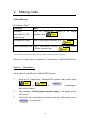
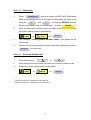
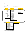
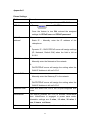
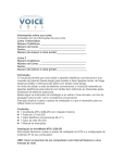
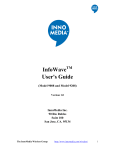
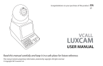
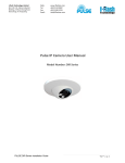
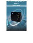
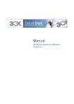
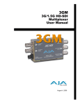
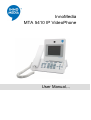
InnoMedia
MTA 5410 IP VideoPhone
User Manual
[v 1.0]
IMPORTANT SAFETY INSTRUCTIONS
When using your telephone equipment, basic safety precautions should
always be followed to reduce the risk of fire, electric shock and injury to
persons, including the following:
•
All the safety and operating instructions should be read before the
appliance is operated.
•
Do not use this product near water for example, near a bathtub,
washbowl, kitchen sink or laundry tub, in a wet basement or near a
swimming pool.
•
Avoid using a telephone (other than a cordless type) during an
electrical storm. There may be a remote risk of electric shock from
lightning.
•
Do not use the telephone to report a gas leak in the vicinity of the leak.
•
Use only the power cord and batteries indicated in this manual. Do not
dispose of batteries in a fire. They may explode. Check with local
codes for possible special disposal instructions.
•
Dangerous high voltages are present inside the enclosure. Do not open
the cabinet.
•
This appliance contains no user serviceable parts. Refer servicing to
qualified personnel only.
SAVE THESE INSTRUCTIONS
CAUTION: To reduce the risk of fire, use only No. 26 AWG or larger (e.g., 24
AWG) UL Listed or CSA Certified Telecommunication Line Cord.
Introduction
MTA 5410 IP VideoPhone, the 3rd generation of InnoMedia videophones,
beside inheriting its predecessor features to continue the offer of real-time
face-to-face Video or Voice call over a broadband IP/3G/PSTN network, this
new model also comes with a sleek, slim LCD panel and stylish casing design
to produce a sophisticated look. In addition, with the Icon based Menu, it
enhance the product user friendliness
Unbeatable user-friendliness
Great viewing pleasure – with MTA 5410 IP VideoPhone, you can enjoy the
comfort of a 4 inch LCD during your video call. Hence when calling another
VideoPhone† you are able to view the remote party.
Up-close and personal – bringing your loved ones up-close on the phone
and let your true expression be seen. MTA 5410 IP VideoPhone gives you a
direct video line to derive pleasure from the warm experience of a face-to-face
conversation.
Icon based Menu – Besides inheriting the plug and play feature from its
predecessor, MTA 5410 IP VideoPhone have a new icon-based menu which
makes it even easier to navigate through the rich spread of features. You can
find Contacts, Settings, Tones & Volume, Info, and Connect/Disconnect
available in the menu.
†
The VideoPhone models in reference are MTA 5531, MTA 5410 and MTA 3368 IP VideoPhone
1
I. Usage Environment
Design to suit both residential and enterprise environment, MTA 5410 IP
VideoPhone achieves best performance when it is being deployed in a
broadband network with the following conditions:
Network that supports 10/100Base Tx Interface
Broadband Internet connections with minimum 64kbps upload and
download speed
NO Firewall configured within the Local Area Network (LAN)
environment
Network that is NOT operating behind Network Address Translation
(NAT)
Provision of a public IP address by DHCP or PPPoE or static
assignment
RJ45 plug required
2
II. MTA 5410 IP VideoPhone Feature
Figure 2.1 MTA 5410 IPVP keyboard panel
S
Feature in reference is applicable to SIP SW only
H
Feature in reference is applicable to H.323 SW only
~ Feature in reference requires check on availability
Number
Components
Function Description
1
< SPEAKER >
To activate speakerphone mode. Press this
button again deactivates the speaker phone
mode and VideoPhone returns to on-hook
status
2
< MENU >
The icon based menu provides access to
various VideoPhone features which include
Contacts, Settings, Tones & Volume,
Info, and Disconnect/Connect
3
< PHONEBOOK >
[SIP] To store and provide reference
functions to phone numbers and respective
names. Accompanying features include,
Search S - specific stored numbers
New
S
– Create and store new phone
numbers
3
Number
Components
Function Description
Manage
S
- Standard phonebook editing
functions (Remove, Edit Name, Edit Tel)
[H.323] To store and provide reference
functions to phone numbers and respective
names. Accompanying features include,
Search H - specific stored numbers
New
H
– Create and store new phone
numbers
H
Options
- Standard phonebook editing
functions (Remove, Edit Name, Edit Tel)
4
< FLASH > ~
Enable line toggling during call waiting
between 2 concurrent calls
5
< MESSAGE > ~
Voicemail function enables incoming PSTN
call only to be diverted to VideoPhone’s
Answering
message
Machine.
retrieval
It
and
also
provide
management
functions to Voicemail
On/Off – To enable/disable the feature
Playback – After scroll to and select the
specific message in the Voicemail list,
press <Playback> or <Enter> button to
listen to the message
Greeting
–
Play/Record/Set
Select
default
either
to
greeting
message
6
< VIEW >
To toggle between SELF view, REMOTE
view or Picture-in-Picture views during
Video calls
7
< MUTE >
To disable the audio transmission on the
VideoPhone, hence remote user will not
hear anything when you speak. Function is
4
Number
Components
Function Description
only applicable to Video and Voice Calls
8
< Function keys >
4 function keys located at the top of the
keyboard panel
To activate the corresponding functions
as shown in the menu bar displayed at
the bottom of the LCD screen
S
9
To dial out the selected numbers and
Video
establish a videoconference session. Video
Call
is
accessible
in
Direct
Dial,
Phonebook, Received Calls and Dialled
Calls mode.
S
10
To dial out the selected numbers and
Voice
establish a voice session via broadband
connection. Voice Call is accessible in
Direct Dial, Phonebook, Received calls
Dialled Calls mode.
11
< Number keypad >
To dial out the remote device contact
number.
To make entries in Phonebook and
configure VideoPhone in Settings
12
< VOLUME + >
To increase the hearing volume of the
speaker
or
handset
mode
during
a
conversation
To increase the ringer volume when
VideoPhone is in idle mode
Up scroll function
13
< VOLUME - >
To decrease the hearing volume of the
speaker
or
handset
mode
during
a
conversation
To decrease the ringer volume when
VideoPhone is in idle mode
Down scroll function
5
Number
14
Components
Function Description
Provide a list of incoming calls to
< Received Calls > S
VideoPhone.
< Incoming Calls > H
Other features available include Call
Details, Add phone number from the list
to Phone Book and standard Call list
management functions
Left scroll function
15
Provide a list of outgoing calls from
< Dialled Calls > S
VideoPhone.
< Incoming Calls > H
Other features available include Call
Details, Add phone number from the list
to Phonebook and standard Call list
management functions
Right scroll function
16
< SELECT >
Located at the middle button of the
navigation key pad
Press once to make selection or activate
setting changes S,H
Press again to store configured setting S,H
During outgoing call, after entering the
phone number press once to activate
calling function H
17
Lighted in green when VideoPhone is power
Power LED
ed up
18
Network LED
Lighted in red when VideoPhone loses
network connection or not ready to make
Video/Voice call
Ring Indicator – LED flashes to notify of
an incoming call
19
Message LED
Blink in amber when VideoPhone receives an
incoming message
20
CCD camera
High quality camera with a ¼" CCD sensor
6
Number
Components
Function Description
21
LCD screen
4 inch TFT colour LCD mounted on a 90
degrees angle adjustable panel
22
Contrast control
To adjust the contrast of the video image.
23
Brightness control
To adjust the brightness of the video image.
7
III. Installation
Below is an illustration of the back panel of the MTA 5410 IP VideoPhone.
Figure 3.1 MTA 5410 IP VideoPhone back panel
On the back of your MTA 5410 IP VideoPhone,
1.
Connect from the WAN port to the broadband modem (if any) by using a
RJ45 Ethernet cable
2.
Plug the power adapter^ into the 12VDC 1.5A power connector
3.
Switch on the MTA 5410 IP VideoPhone
4.
The POWER LED (green) will light up while your VideoPhone starts to
boot up and conducts a series of diagnostic tests
5.
Once the boot-up process is completed, the LCD screen will display a
self-view
^ Check that you have the correct power rating for your power adapter
8
IV. Configuration
The following will explain the user settings for 3 different types of Broadband
service connection:
A1.
DSL users with PPPoE login
A2.
DSL users without login
A3.
Cable modem users
9
A1. DSL users with PPPoE login
For initial PPPoE set-up. User should enter the user name and password
provided by user ISP
1.
On the default self-view mode, press
MENU
button to access
SELECT
button to open
the Menu page
2.
Navigate to Settings icon and press
Settings option
Phone Settings
3.
Scroll cursor to select
4.
Scroll cursor with
+
5.
Press
to change PPPoE setting to ON
6.
Scroll cursor to PPPoE user setting
7.
Press
SELECT
and
buttons to PPPoE setting
−
and enter the assigned PPPoE username
SELECT
provided by your ISP via the number pad
SELECT
8.
Once setting is configured press
9.
Scroll cursor to PPPoE password setting
10.
Press
SELECT
to store configuration
and enter the assigned PPPoE password
provided by your ISP via the number pad
11.
Once setting is configured press
12.
Re-enter the PPPoE password again, follow by
store the PPPoE password and
to confirm configuration
SELECT
Done
SELECT
to
to continue with other
settings configuration
13.
Press
Exit
to return to Settings page
Remarks: Refer to MTA 5410
NAT Settings
to work behind VideoPhone NAT mode
10
configuration to allow PC
A2. DSL users without login
By default, there is no additional setting and the MTA 5410 IP VideoPhone is
ready to make calls.
Remarks: Refer to MTA 5410
NAT Settings
configuration to allow PC to
work behind VideoPhone NAT mode
If user is using fixed IP address, please refer to *Fixed IP set-up before
making any calls.
A3. Cable modem users
By default, there are no additional settings and the MTA 5410 IP VideoPhone
is ready to make calls.
Remarks: Refer to MTA 5410
NAT Settings
configuration to allow PC to
work behind VideoPhone NAT mode
If user is using fixed IP address, please refer to *Fixed IP set-up before
making any calls.
11
*Special case: Fixed IP set-up
1.
On the default self-view mode, press
button to access
MENU
the Menu page
2.
Navigate to Settings icon and press
SELECT
button to open
Settings option
3.
Scroll cursor to select
4.
Scroll cursor with
Phone Settings
+
and
−
buttons to WAN IP
address S setting
5.
Press
SELECT
and enter the assigned IP address as provided
by your ISP via the number pad
6.
Once setting is configured press
7.
Repeat step 4 – 6 to configure WAN Netmask
settings
12
SELECT
to store configuration
S
and Default GW
MTA 5410 IP VideoPhone NAT Settings
To enable the NAT Settings on MTA 5410 IP VideoPhone
1.
On the default self-view mode, press
MENU
button to access
the Menu page
2.
Navigate to Settings icon and press
SELECT
button to open
Settings option
3.
Scroll cursor to select
4.
Scroll cursor with
NAT Settings
+
and
the following settings
NAT – ON
Priority Switch – ON
DHCP – ON
13
−
buttons and turn ON
When your MTA 5410 IP VideoPhone NAT and DHCP modes are switched
OFF, to share your videophone and PC with a single network connection:
a.
Disconnect MTA 5410 IP VideoPhone
If user wants to disconnect the Internet connection on the MTA 5410,
press
SELECT
MENU
and scroll cursor to
Disconnect
icon, press
to disconnect and swap the Ethernet cable from the
MTA 5410 WAN port to other devices, e.g. PC, before establishing an
Internet connection on the PC
b.
Connect MTA 5410 IP VideoPhone
User has to disconnect the Internet connection on the PC, and swap
the Ethernet cable to the MTA 5410, and establish an Internet
MENU
connection on the MTA 5410 by pressing
cursor to
SELECT
icon, press
Connect
and scroll
to connect
Connect and Disconnect an Internet connection on the PC
a.
To disconnect an Internet connection on the PC, you should release
the IP address from the PC by typing the following in the command
prompt window:
b.
Window 98/ME:
“ipconfig /release_all”
Window 2000/XP:
“ipconfig /release”
To establish an Internet connection on the PC, you should get an IP
address from the service provider by typing the following in the
command prompt window:
Window 98/ME:
“ipconfig /renew_all”
Window 2000/XP:
“ipconfig /renew”
14
B. After set-up
When all the above settings are correctly configured, MTA 5410 IP
VideoPhone will perform configuration work and reboot automatically, and will
display the following messages on the LCD
< Initializing network, please wait… >
< Profile updating, please wait… >
< Upgrading system, please DO NOT switch off… >
< Registering, please wait… >
Once successfully registered to Service Provider’s network, the MTA 5410 is
ready to make calls
15
V. Making Calls
Calling Methods
At-A-Glance Table S
Calling to
Dial
Another IP
Dial <IP VideoPhone† number or 3G mobile
VideoPhone† or 3G
number> and
Video
mobile phone
Local/Mobile number
Dial <Local /Mobile number> and
Voice
Other countries by IDD
Dial < IDD prefix> <Country code> <Area code>
<Phone number> and
†
Voice
The VideoPhone models in reference are MTA 5531, MTA 5410 and MTA 3368 IP VideoPhone
There are 3 simple ways to call another IP VideoPhone†, Mobile/PSTN phone:
Method 1 - Direct Dial S, H
Call another IP VideoPhone† or Mobile/PSTN phone
1.
Enter the IP VideoPhone† /Mobile/PSTN number, then select either
dsfdsfs
S
S
Video
or
Voice
SELECT
or
H
accordingly to
dial out the number
2.
The message < Dialing (phone number, name) > will appear on the
LCD screen
3.
Wait for the call to be picked up at the remote end. Alternatively, press
SPEAKER
to cancel call
16
Method 2 - Phonebook
1.
PHONEBOOK
Press
button to access the MTA 5410 Phonebook.
Either scroll through the list to the name of the person you wish to call
using the
and
+
or using the SEARCH function
−
[Entering the name using the number pad S or press
2.
Search
H
]
Once the name of the person whom you wish to call is selected, select
the correct calling mode to start dialling.
S
Video
3.
S
or
H
Voice
or
SELECT
The message < Dialing (phone number, name) > will appear on the
LCD screen
4.
Wait for the call to be picked up at the remote end. Alternatively, press
SPEAKER
to cancel call
Method 3 – Received /Dialled Calls
1.
Press either button
or
2.
Scroll through the call records and select the contact numbers to call
3.
Select the correct calling mode to start dialing
S
Video
S
or
Voice
H
or
S
Feature in reference is applicable to SIP SW only
H
Feature in reference is applicable to H.323 SW only
17
SELECT
VI. Receiving Calls
A. Manual answering using handset or speakerphone
When there is an incoming call, the MTA 5410 IP VideoPhone will ring and
the Network indicator (red LED) will start flashing. At the same time, the LCD
screen will display the contact number of the caller.
simply pick up the handset or press . SPEAKER
To answer the call,
to engage in speakerphone
mode.
B. Auto answer mode
User may also enable the Auto Answer feature so that MTA 5410 IP
VideoPhone user will automatically answer an incoming call. To enable this
feature, press the
MENU
button, scroll cursor to select
scroll to Auto answer and press
SELECT
Call Settings ,
button to set either 1 ring, 2 rings,
3 rings, 4 rings or 5 rings. An indicator "A" will be shown on the screen when
the feature is activated.
To disable Auto Answer feature, select Never.
To enable Auto Answer password
password
dgSELECT
S
S
mode, scroll and select AutoAns
setting, configure a password (maximum 6 digits) and press
button to save the password
When a call is made from another VideoPhone, a blue page with a key-shape
pattern will be shown on the caller’s screen, the caller can activate the Auto
Answer feature by entering the correct password followed with the # key. The
call will be terminated in 30 seconds if no correct password is being entered.
To disable the password protection, simply leave the AutoAns Password
field blank.
*Note: Auto Answer password protection is a Video Call feature.
18
S
C. During calling session
Once the call is successfully established with another MTA 5410 IP
VideoPhone, user will immediately see the image of the person you are
talking to. There are some features that user can tune or adjust to optimise
your videoconferencing experience:
i)
Volume
The
+
−
and
buttons allows you to adjust the loudness
of the speaker or handset
ii)
Audio Mute
Press
MUTE
to disable your voice from being transmitted if you
do not wish to be heard by the remote user
iii)
Privacy mode
Press
Privacy
blocks your image from being transmitted so that
the remote user sees only a blue screen
iv)
Brightness & Contrast
The brightness and contrast can be controlled using the respective
buttons by the top of the LCD panel
19
VII. Other Functions
MTA 5410 IP VideoPhone – One Connection
Able to connect with TV set
for enlarging video size
VIII. Other Functions
Simultaneous usage
of VideoPhone &
Internet
MTA 5410 – One Connection
Able to connect with digital
camcorder, video recorder or
other Audio/Video appliance
20
Frequently Asked Questions
Q1:
MTA 5410 IP VideoPhone displays a message “Searching …” on
the bottom right hand corner of the LCD screen, and the LED
indicator turns red.
A1:
There are some possibilities:
1. On the VideoPhone, go to “About” page and ensure the user can
see a value in the Phone number and IP address. If not, switch off
the VideoPhone, reset the DSL/cable modem (if any), and switch on
the VideoPhone again.
2. Make sure the VideoPhone has proper network settings according
to the “Configuration” section of the manual.
Q2:
MTA 5410 IP VideoPhone has no self-view.
A2:
Please try the followings:
1. Press
MENU
button , scroll and select
Settings
and
Phone Settings to ensure the “Video source” is set to
“Internal” camera mode.
2. Ensure the camera shutter is open
Q3:
MTA 5410 IP VideoPhone is unable to call another VideoPhone.
A3:
Make sure the message “Searching …” is not shown on the LCD
screen. Check if the RJ-45 Ethernet cable is connected properly to the
WAN port of the VideoPhone. If problem persists, reboot the
VideoPhone and try again.
Q4:
MTA
5410
IP
VideoPhone
displays
a
message
“Network
Unavailable” on the LCD screen when trying to make an outgoing
call.
A4:
Make sure the message “Searching …” is not shown on the LCD
screen. Check if the RJ-45 Ethernet cable is connected properly to the
WAN port of the VideoPhone. If problem persists, reboot the
VideoPhone and try again.
21
Q5:
MTA
5410
IP
VideoPhone
displays
a
message
“Number
Unavailable” on the LCD screen when trying to make an outgoing
call.
A5:
The VideoPhone of the called party is not reachable temporarily due to
network outage, or it may be switched off. Try calling the remote party
at a later time.
Q6:
Cannot see the VideoPhone user from the other end.
A6:
There are some possibilities:
1. Ensure the “Privacy” mode of the other end is not activated.
2. Make sure the LCD screen is displaying the remote view, or the
picture-in-picture view by pressing the
VIEW
button.
Q7:
Cannot hear the VideoPhone user from the other end.
A7:
Ensure the
Q8:
During PPPoE login, LCD display message <PPPoE login failed >
A8:
Ensure the correct PPPoE user and PPPoE password are configured
MUTE
mode of the other end is not activated.
in the VideoPhone and try the PPPoE login again
22
Appendix A:
[SIP] Navigation Menu
The following chart is an overview of the SIP SW Navigation Menu
Contacts
Phonebook
Video
Voice
Search
Options
New
Manage
Remove
Edit Name
Edit Tel
Received Call
Dialled Call
Video
Voice
Clear all
Call Details
Remove
Add to Phbk
Settings
Tones & Volumes
Call Settings
Auto answer
AutoAns password
Tones Selection
Telephone Ring Tone
VCall RingTone
Phone Settings
User name
PPPoE
PPPoE user
PPPoE password
WAN IP address
WAN Netmask
Default GW
Pri DNS address
Sec DNS address
Timezone GMT
Screensaver
Video source
Language
Time
Tones Volume
NAT Settings
NAT
LAN IP address
LAN Netmask
Priority Switch
DHCP
LAN IP start
LAN IP end
IP Lease Time
Info
About
Phone number
WAN IP Address
WAN Netmask
Default GW
Pri DNS address
Sec DNS address
MAC address (WAN)
MAC address (LAN)
Connect / Disconnect
Yes
No
Version (Model No - Protocol)
OS version
Video version
Audio version
SW version
HW version
Config version
23
Handset Volume
Speaker Volume
Appendix B:
[H.323] Navigation Menu
The following chart is an overview of the H.323 SW Navigation Menu
Contacts
Settings
Phonebook
Search
Options
Remove
Edit Name
Edit Tel
New
Incoming Call History
Outgoing Call History
AddPhbk
Delete
Details
•
Name
•
Telephone or IP
•
Start time
•
Duration
•
Status
Tones & Volumes
Call Settings
Auto answer
Phone Settings
IP address
Netmask
Default GW
Pri DNS address
Sec DNS address
PPPoE
PPPoE user
PPPoE password
Timezone GMT
Screensaver
Video source
Language
Tone Selection
Telephone Ring Tone
VCall RingTone
Tones Volume
Handset Volume
Speaker Volume
NAT Settings
NAT
LAN IP address
LAN Netmask
Priority Switch
DHCP
LAN IP start
LAN IP end
IP Lease Time
Info
Connect / Disconnect
About
Phone number
IP Address
Netmask
Default GW
DNS address 1
DNS address 2
MAC address 1
MAC address 2
Yes
No
Version (Model No - Protocol) **
OS version
Video version
Audio version
SW version
HW version
** Press F1 and F2 buttons to access Version
24
Appendix C:
Phone Settings
Fields
Remarks
User name
A generic name that is assigned to your MTA 5410
PPPoE
Press
SELECT
to turn ON/OFF feature
Once the feature is turn ON, entered the assigned
settings for PPPoE user and PPPoE password
WAN IP
Either
address^
Static IP – Manually enter the IP address of the
videophone.
Or
Dynamic IP – DHCP/PPPoE server will assign settings
(IP, Netmask, Default GW) when the field is left as
0.0.0.0
WAN Netmask^
Either
Manually enter the Netmask of the network
Or
DHCP/PPPoE server will assign the setting when the
WAN IP Address is left as 0.0.0.0
Default GW^
Either
Manually enter the Gateway IP in the network
Or
DHCP/PPPoE server will assign the setting when the
WAN IP Address is left as 0.0.0.0
Timezone GMT
Scroll and select one out of the 29 pre-configured time
zones
Screensaver
This feature enables the LCD to activate screensaver
when VideoPhone is engaged in power save mode.
Selectable settings are 2 mins, 10 mins, 30 mins, 1
hour, 2 hours and Never
Video source
Select Internal to enable the embedded camera in
25
Fields
Remarks
VideoPhone or External for other external camera source
Language
Select English or Simplified Chinese for the preferred
language display in Menu and LCD messages
Time
Configure the time and date on the VideoPhone
Call Settings
Fields
Remarks
Auto answer
Select 1 ring, 2 rings, 3 rings, 4 rings or 5 rings. To
enable the VideoPhone to auto answer mode. Select Off
to disable feature
AutoAns
Configure a password (1-6 digits). Any received calls
password S ↵
would require incoming caller to enter the password
before the VideoPhone allows video image transmission
NAT Setting
Fields
NAT
Remarks
Turn ON NAT mode, the VideoPhone will provide basic
routing functions for LAN devices (e.g. PC) that are
connected via VideoPhone’s PC port
Turn OFF NAT mode, the VideoPhone will assume
bridge mode function, hence other end devices
connected to the VideoPhone will either alternate the
same set of network settings or have a separate sets
of settings
LAN IP address~
Configure a LAN IP address for the VideoPhone
LAN Netmask~
Configure a LAN Netmask for the VideoPhone and other
LAN devices
Priority Switch
Turn ON to give priority for media packets (Voice and
Video) transmission
Turn OFF to assign same priority to both media and
data packets transmission
26
DHCP~
Turn ON for the VideoPhone to assign a dynamic IP
settings to PC LAN devices (e.g. PC)
LAN IP Start~
The first IP address within the range of LAN setting
LAN IP End~
The last IP address within the range of LAN setting
IP Lease Time~
The duration for LAN devices to assume the LAN settings
assigned by the VideoPhone
^ Compulsory settings
~ Require NAT turn ON in MTA 5410 IP VideoPhone
↵
Require Auto Answer turn ON in MTA 5410 IP VideoPhone
S
Feature in reference is applicable to SIP SW only
H
Feature in reference is applicable to H.323 SW only
Appendix D:
Character Map
Number keys
0
1
2
3
4
5
6
7
8
9
Characters
0 @ _ & ~ ( ) + * / = < > # $ % ^
. 1 ? ! , ' " - : ;
A B C 2
D E F 3
G H I 4
J K L 5
M N O 6
P Q R S 7
T U V 8
W X Y Z 9
27
Product Approval Information
1.
FCC PART 68 INFORMATION
This equipment is Hearing Aid Compatible.
This equipment complies with Part 68 of the FCC Rules and the requirements adopted by ACTA. On the bottom of
this equipment is a label that contains, a product identifier in the format US:AAAEQ##TXXXX. If requested, this
information must be provided to your telephone company.
A plug and jack use to connect this equipment to the premises wiring and telephone network must comply with the
applicable FCC Part 68 rules and requirements adopted by ACTA. A compliant telephone cord and modular plug
is provided with this product. It is designed to be connected to a compatible modular jack that is also compliant.
See installation instructions for details.
The REN is used to determine the number of devices that may connect to a telephone line. Excessive RENs on a
telephone line may result in the devices not ringing in response to an incoming call. In most but not all areas, the
sum of the RENs should not exceed five (5.0). To be certain of the number of devices that may be connected to a
line, as determined by the total RENs, contact your local telephone company. For product approved after July 23,
2001, the REN for this product is part of the product identifier that has the format US:AAAEQ##TXXXX. The
digits represented by ## are the REN without the decimal point (e.q., 03 is a REN of 0.3). For earlier products, the
REN is separately shown on the label.
If this equipment MTA 5XXX-XYX IP VideoPhone(where X= any number 0-9 and Y= any alphabet A-Z) causes
harm to the telephone network, the telephone company will notify you in advance that temporary discontinuance
of service may be required. But if advance notice is not practical, the telephone company will notify the customer
as soon as possible. Also, you will be advised of your right to file a complaint with the FCC if you believe it is
necessary.
The telephone company may make changes in its facilities, equipment, operations or procedures that could affect
the proper functioning of your equipment. If they do, you will be notified in advance in order for you to make
necessary modifications to maintain uninterrupted service. If trouble is experienced with this unit, for repair or
warranty information, please contact customer service at the address and phone listed below. If the equipment is
causing harm to the network, the telephone company may request that you disconnect the equipment until the
problem is resolved.
DO NOT DISASSEMBLE THIS EQUIPMENT. It does not contain any user serviceable components.
We recommend the installation of an AC surge arrester in the AC outlet to which this equipment is connected.
Telephone companies report that electrical surges, typically lighting transients, are very destructive to customer
terminal equipment connected to AC power sources.
Attn: Customer Service Dept
InnoMedia, Inc.
186 Topaz Street
Milpitas, CA 95035-5429
Tel: (408) 432-5400
Fax: (408) 432-5404
II. FCC DECLARATION OF CONFORMITY
PRODUCT NAME: Multifunctional Telephone with IP Videophone
MODEL NUMBER: MTA 5XXX-XYX (where X= any number 0-9 and Y= any alphabet A-Z)
FCC RULES: TESTED TO COMPLY WITH FCC PART 15, CLASS B
OPERATING ENVIRONMENT: FOR HOME OR OFFICE USE
FCC COMPLIANCE STATEMENT:
This device complies with part 15 of the FCC Rules. Operation is subject to the following two conditions: (1) This
device may not cause harmful interference, and (2) this device must accept any interference received, including
interference that may cause undesired operation.
28
INFORMATION TO USER:
This equipment has been tested and found to comply with the limits of a Class B digital device, pursuant to Part 15
of the FCC Rules. These limits are designed to provide reasonable protection against harmful interference in a
residential installation. This equipment generates, uses and can radiate radio frequency energy and, if not installed
and used in accordance with the instructions, may cause harmful interference to radio communications. However,
there is no guarantee that interference will not occur in a particular installation, if this equipment does cause
harmful interference to radio or television reception, which can be determined by turning the equipment off and
on, the user is encouraged to try to correct the interference by one or more of the following measures:
1. Reorient/Relocate the receiving antenna.
2. Increase the separation between the equipment and receiver.
3. Connect the equipment into an outlet on a circuit difference from that to which the receiver is connected.
4. Consult the dealer or an experienced radio/TV technician for help.
CAUTION: Changes or modifications not expressly approved by the manufacturer responsible for compliance
could void the user’s authority to operate the equipment.
THE PARTY RESPONSIBLE FOR PRODUCT COMPLIANCE
InnoMedia, Inc.
186 Topaz Street
Milpitas, CA 95035-5429
Tel: (408) 432-5400
Fax: (408) 432-5404
29