1
06/2009
Mod:TGV/35DW
Production code: PROFIGEL 350 WATER
3
Dear customer,
we congratulate you for choosing a high quality product
which will surely satisfy your expectations.
With our thanks for choosing us,
we kindly invite you to examine the present operating
instructions manual before operating your new device.
SUMMARY
1
2
IMPORTANT SAFETY SUGGESTIONS AND
PRECAUTIONS ...................................................... 4
Lid's magnetic sensor ..................................... 5
Chute with protection flap ................................ 5
Extraction door's grill....................................... 6
6.6
6.7
6.8
6.9
TECHNICAL DATA .................................................. 6
3.1
3.2
DEVICE’S OPERATION .........................................12
6.1
6.2
6.3
6.4
6.5
SAFETY DEVICES .................................................. 5
2.1
2.2
2.3
3
6
Technical data plate and CE marking .............. 6
Acoustic pressure level ................................... 6
7
4
CARRYING AND UNPACKING ............................... 7
4.1
4.2
5
INSTALLATION ...................................................... 8
5.1
5.2
5.3
5.4
5.5
Placing and check of the parts ........................ 8
Device’s parts reassembling ............................ 9
Electrical connection ....................................... 9
Connecting to water supply
(water condensing machines) ......................... 10
Initial functioning check .................................. 11
WASHING .............................................................19
7.1
7.2
7.3
7.4
7.5
Transportation of the packed device ................ 7
Unpacking ....................................................... 7
Warnings ....................................................... 12
Controls and indicators ..................................12
Setting Up......................................................14
Setting up for production ................................16
ECONOMIZER function (ECOGEL and
EUROGEL models only) ................................16
TEMPERATURE Cycle production .................16
TIME Cycle production ................................... 17
SLUSH (Crushed ice-drink) production ...........18
Extracting the product ....................................19
8
Rinse - preliminary wash ................................19
Parts disassembling ......................................20
Washing ........................................................20
Parts reassembling ........................................ 22
Sanitation ......................................................22
MAINTENANCE .....................................................23
8.1
8.2
8.3
9
Maintenance during the components
disassembling ................................................23
Check of safety devices .................................24
Yearly maintenance .......................................24
PERIODS OF INACTIVITY ....................................24
10 MALFUNCTIONS .................................................. 25
WARNING:
GENERAL/MECHANICAL
DANGER
DANGEROUS
VOLTAGE
A TEXT IN UPPER-CASE, IDENTIFIED BY ONE OF THE SYMBOLS ABOVE, CONTAINS INSTRUCTIONS
THAT, IF NOT FOLLOWED, MAY CAUSE HARM TO PEOPLE.
A text in lower-case, identified by this symbol, contains instructions that, if not followed, could cause
damages or malfunctions to the device, or falls in its quality.
English
Vertical batch freezer
4
1
IMPORTANT SAFETY
SUGGESTIONS AND PRECAUTIONS
CAREFULLY READ THE INSTRUCTIONS CONTAINED IN THE PRESENT OPERATING INSTRUCTIONS
MANUAL BEFORE INSTALLING AND OPERATING THIS DEVICE. THESE INSTRUCTIONS HAVE BEEN
DRAFTED FOR THE SAFETY OF INSTALLATION, OPERATION AND MAINTENANCE OF THIS DEVICE.
The present manual of Operating Instructions, placed on the device in the packing and supplied with the Technical
Handbook, the EC’s conformity certification and the electrical tests schedule, is an essential part of the Batch Freezer
(also defined, in the present manual of operating instructions, simply with the term, device) and must be preserved for
any future consultation.
The Technical Handbook must always be given, together with the device, to the Assistance Service’s personnel or to
the technicians to whom you will eventually request assistance.
In case of selling or transferring to other user, all the above mentioned documentation must be handed to the new
user, so that he can be informed of the operation and relative technical information and safety instructions.
DO NOT INTRODUCE YOUR FINGERS OR OBJECTS IN THE DEVICE’S LOOPHOLES.
DO NOT REMOVE OR HIDE, FOR ANY REASON, ANY LABEL APPLIED ON THE DEVICE.
NEVER OPEN THE PROTECTING PANELS. THE DEVICE DOES NOT CONTAIN, IN ITS INSIDE, PARTS
WHICH CAN BE OPERATED BY THE USER.
THE USER MUST NOT EXECUTE OPERATIONS WHICH ARE NOT CLEARLY CONTAINED IN THE
PRESENT USER’S MANUAL. ANY OPERATION WHICH REQUIRES TOOLS NOT GIVEN IN THE DEVICE’S
EQUIPMENT IS TO BE CARRIED OUT ONLY BY THE ASSISTANCE SERVICE OR BY TECHNICALLY
AUTHORISED PERSONNEL.
Always turn power supply off before undertaking any operation requiring access to the device’s moving parts (beater,
cylinder or extracting door).
Any modifying of the electrical supply must be exclusively performed by professionally qualified and certified personnel.
Any use of the device that is not for the production of ice-cream, ice-cream cake or slush, is to be considered
improper.
The device has been made to be operated by adults, prohibit children to play with it.
Modifying, or attempting to modify this device, can be dangerous and would void any type of warranty.
Always use original spare parts.
It is important to adopt the following precautions to avoid damages at the cylinder, at the beater or any
other mechanical part:
-
Do not drop them and do not expose them to bumps;
-
do not operate the device dry, with a bad quality mixture or in a quantity lower or higher to that recommended:
while inside the cylinder, the ice-cream lubricates the cylinder’s sides as well as cooling down the beater, thus
stabilizing its temperature;
-
The beater and the cylinder are disposals built and paired with precision: for this reason they are very sensible to
temperature changes, that may cause eventual damages at the mechanical parts of the device. NEVER expose
to abrupt temperature changes the parts subject to refrigeration: DO NOT pour water in the cylinder immediately
after ice-cream has been produced.
In the event of the use of the device being no longer required, deactivate the machine by severing the electric cable
(after unplugging it from wall socket). In addition, follow these recommendations:
-
avoid dispersing the freezing gas and the oil contained in the device;
-
carry out the draining and/or recycling according to the local provisions of the law currently in force on this matter.
English
Operating instructions
2
5
SAFETY DEVICES
DO NOT ALTER THE SAFETY DEVICES AND DO NOT UTILIZE THE MACHINE IF THE SAFETY DEVICES
ARE DAMAGED OR MALFUNCTIONING.
THE MANUFACTURER IS NOT RESPONSIBLE FOR POSSIBLE DAMAGES CAUSED TO PEOPLE OR
OBJECTS BY THE ALTERING OR BYPASSING SUCH DEVICES OR RELATIVE CIRCUITS.
2.1
Lid's magnetic sensor
This safety device, featuring an approved type magnet [1] and a magnetic contact [2]
avoids accidents caused by the accidental starting of the beater when the lid is open.
In consequence the device can't operate when the lid is open, and if it is opened during
its functioning the beater immediately stops.
In any case the lid's magnetic sensor MUST NOT be considered a control to be used
for the normal stop of the device.
DURING THE NORMAL USE, THE DEVICE MUST BE STOPPED ONLY
BY USING THE BUTTONS ON THE CONTROL KEYPAD, AND NOT BY
OPENING THE LID.
The magnet [1] and the magnetic contact [2] MUST be assembled as follows: the grooves [3] and the stencilled semicircle
[5] on the bottom of the magneto [1] must coincide with the grooves [4] (marked by a white line down the side) and the
stencilled semicircle [6] on top of the magnetic contact [2]. The device will not work unless all parts have been correctly
assembled in accordance with these instructions.
2.2
Chute with protection flap
The extraction door chute has a tilting protection flap [A]. The product during extraction lifts this. The flap together with the
fixed grill [F] prevents fingers or objects from being ACCIDENTALLY inserted through the extraction door.
In order to ensure a regular operation no protection was possible as to prevent fingers and objects from being VOLUNTARILY inserted through the extraction door (according to Machines Directives 89/392/CEE and ensuing modifications, appendix I, Art. 1.1.2.b, 3 rd paragraph). Due to its thickness and small pieces of dried or fresh fruit, the finished
product must be completely extracted through a short, wide and unobstructed aperture.
INELIMINABLE HAZARD: WHEN THE MACHINE IS OPERATING YOU MUST NOT MANUALLY
RAISE THE PROTECTION COVER [A]; YOU MUST NOT UNDER ANY CIRCUMSTANCES WHATSOEVER INSERT HANDS OR OBJECTS THROUGH THE FIXED GRID [F] OR THE HATCH. IF THIS
ADVICE IS NOT ADHERED TO THE OUTCOME COULD BE FINGER AMPUTATION (THE BEATER/
MIXER PASSES VERY CLOSE TO THE HATCH ) OR SERIOUS DAMAGE TO THE MACHINE (WHERE
OBJECTS ARE USED).
Note:
The machine will not operate without the protection flap since the flap includes a safety magnetic contact
[C] and its magnet [B] (89/392/CEE and ensuing modifications, Appendix 1, Art. 1.1.2.b, 2nd paragraph).
THE MAGNETS AND THEIR CONTACTS ARE IMPORTANT SAFETY DEVICES!
The user is warned of the above INELIMINABLE HAZARD (89/392/CEE and ensuing modifications, Appendix. I,
Art. 1.1.2.b, 3rd paragraph and 1.7.2) by a plate [E] affixed next to the extraction chute, which is in position even
when no protection flap is installed.
English
Vertical batch freezer
6
2.3
Extraction door's grill
In some models, a fixed protection grill [3] prevents fingers or objects from being
ACCIDENTALLY caught inside the extraction chute. In order to insure normal operation it is not possible to adjust the fixed grill as to prevent fingers and objects from
being VOLUNTARILY inserted through the extraction chute (according to Machines
Directive 89/392/CEE and ensuing modifications, Appendix I, Art. 1.1.2.b, 3rd paragraph).
RESIDUAL HAZARD: DO NOT FOR ANY REASON INSERT FINGERS
OR OBJECTS THROUGH THE GRILL OF THE EXTRACTION DOOR
WHEN THE DEVICE IS IN FUNCTION.
The user is warned of the above residual hazard (89/392/CEE and ensuing modifications, Appendix. 1, Art. 1.1.2.b, 3rd paragraph and 1.7.2) by a plate [30] affixed next to the extraction chute.
DO NOT HANDLE OR REMOVE THE GRILL [3] FROM ITS SETTING IN
THE EXTRACTION DOOR!
3
3.1
TECHNICAL DATA
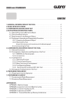
Technical data plate and CE marking
The technical data plate and CE marking must not be removed. It is located on the back part of the device and identifies:
-
the name and address of the manufacturer [1];
-
the designation of the model [2] and the relative series number [3];
-
the type and quantity of freezing gas contained [4];
-
the year of construction [5];
-
the values of voltage and frequency [6], and the power [7] and current [8] consumption;
-
the CE marking [9].
3.2
Acoustic pressure level
The average equivalent continuous acoustic pressure level of this device is quoted in the Technical Handbook (Technical
Data section). This data has been measured at 1 meter from the surface of the device and at 1.60 meters from groundlevel, during the device’s functioning.
English
Operating instructions
4
7
CARRYING AND UNPACKING
Note:
We suggest you to let the Assistance Service or qualified technicians carry out the transportation, unpacking
and installation.
TO LIFT THE DEVICE ALWAYS USE AN ADEQUATE LIFTING DEVICE.
ATTEMPTING TO LIFT IT MANUALLY IS DANGEROUS AND CAN DAMAGE YOUR HEALTH.
The device’s weight specifications, both inclusive of packaging and net, can be found
in both the supplied documents and on the packaging itself.
To prevent the oil contained in the compressor to flow into the refrigerating circuit, it is necessary to
always keep the device in upright position, both during carrying and during the installation and operation. Always follow the instructions on the packing.
4.1
Transportation of the packed device
The packing has been projected to assure at the device the highest protection.
It is therefore suggested to transport the device while it is packed as near as possible
at the place where it will be installed.
To carry the packed device, use an elevator, or a bench trolley, inserting its forks in
the basement’s holes.
4.2
Unpacking
-
WOOD PACKING: unnail the top panel, then separate the lateral panels.
-
CARDBOARD PACKING; cut the strips and remove the cardboard from the top;
After having opened the packing, make sure the device isn’t damaged. In case of doubt, do not use it, and call the Seller.
THE OPENING OF THE LATERAL PANEL IS ONLY ALLOWED TO THE ASSISTANCE SERVICE OR TO
QUALIFIED TECHNICIANS AND MUST BE MADE BEFORE CONNECTING IT. MAKE SURE NOT TO DAMAGE THE INTERNAL PARTS OF THE DEVICE.
-
Remove both the lateral panels unscrewing the relevant fixing screws [21];
-
Find and unscrew the bolts [22] which fix the device’s frame at the packing’s basement;
The outlet of the supply cable is placed on the device’s lower side. During the lifting make sure not to
damage it.
English
Vertical batch freezer
8
-
Lift the device from the basement, possibly working on the lower side, near the wheels, and however, only on the
frame’s carrying parts. Remove the basement, and lean the device on the floor avoiding bumps;
DO NOT insert objects, ropes or brackets for the lifting THROUGH the device, since these could damage
the inside parts.
-
Re-close the lateral panels;
-
Replace or move the packing, which is produced with entirely recyclable materials (
5
).
INSTALLATION
THE INSTALLATION MUST BE CARRIED OUT ONLY BY THE ASSISTANCE SERVICE OR BY TECHNICALLY AUTHORISED PERSONNEL AND IN COMPLIANCE WITH THE LAWS IN FORCE, ALWAYS FOLLOWING INSTRUCTIONS OF THE MANUFACTURER.
5.1
Placing and check of the parts
Place the device on the floor, on a flat and steady surface.
Install the device away from any source of heat, avoiding a direct exposition to sun
radiation and making sure that air can freely circulate around each side of the device
itself.
The devices with AIR CONDENSING need at least a 50 cm free space in
front of the condenser’s grill, to assure the refrigerating plant correct
functioning. Further information are reported on the Technical Book
(Technical Data section).
Check that the machine is supplied with the lid [5] and that the beater [6] is correctly fixed inside the cylinder with its knob
[7]. The bigger models are supplied with a tilting blade [23] and its fixing knob [24].
Also make sure that in the packing there are the device’s following parts:
-
the extraction door’s chute [9], including extraction lid’s protection flap [29] (in some models the chute is already preinstalled);
-
basin support [10] complete with storage cup [11];
-
tube-brush [12] and ice cream’s blade [13];
-
all the technical documentation (in addition to this handbook): the Technical Handbook, the CE’s Conformity Certification and Electrical Test’s Schedule.
English
Operating instructions
5.2
9
Device’s parts reassembling
REASSEMBLY MUST BE CARRIED OUT BEFORE CONNECTING MACHINE TO ELECTRIC OUTLET.
-
Bring lever [8] in operative position (perpendicular to the extraction door) by loosening and then tightening bolt [39].
Use the 3mm allen key [40] provided.
-
if the chute [9] is furnished dismantled, install it below the extraction door [14] fixing it at the frontal panel through the
hand screw [15];
-
install the basin support [10] fixing it at the frontal panel through the hand screws [16].
Note:
5.3
The machine will not operate without the protection flap since the flap includes a safety magnetic contact and its
magnet.
Electrical connection
THE SUPPLY VOLTAGE REQUIRED BY THE DEVICE IS HIGH, SO, IT IS PARTICULARLY DANGEROUS.
THE WORKS ON THE ELECTRICAL SUPPLY CIRCUITS MUST BE MADE WORKMANLIKE BY QUALIFIED STAFF.
THE ELECTRICAL SAFETY OF THIS AUTOMATIC CREAM-WHIPPER
IS REACHED ONLY WHEN THE SAME IS CORRECTLY CONNECTED,
BY QUALIFIED AND CERTIFIED PERSONNEL, TO AN EFFICIENT
EARTHING SYSTEM, MADE AS PROVIDED FOR IN FORCE SAFETY
REGULATIONS.
The manufacturer must not be considered responsible for eventual damages
caused by an inadequate electric plant or earthing.
All the device’s electrical features required for the system’s proportioning are reported
on the Technical Data Plate and on the Technical Handbook.
FOR THE PREPARATION OF THE ELECTRICAL PLANT WHICH SUPPLIES THE DEVICE, IT IS COMPULSORY TO FOLLOW THE PRESCRIPTIVE STANDARDS IN FORCE. IN PARTICULAR:
-
The electrical capacity of the plant must exactly match the supply’s voltage and frequency required by the device;
-
the current capacity of the plant must be suitable for the device’s input;
-
the plant must end with an accepted 5 pole (380V-415V-3~), or 4 pole (200V-220V-3~), or 3 pole (220V-1~), electrical
socket and with electrical and mechanical suitable characteristics. The electrical socket’s poles must be marked with
appropriate letters (phases R-S-T + neutral N + earth); the earth’s pole must be recognizable;
-
The electrical socket must prevent, through appropriate mechanical measures, the plug’s wrong connection;
-
the electrical socket must have, above or annexed, a breaker, conformed to the in force safety laws, with an associated gearing positioned near the device, in a place easily reachable by the operator. It must also be protected by
fuses, above or annexed, with characteristics suited at the current absorbed by the device.
A WRONG CONNECTION ON THE EARTH TERMINAL MAY CAUSE SERIOUS DANGER.
English
Vertical batch freezer
10
A 5 pole (380V-415V-3~), or 4 pole (200V-220V-3~), or 3 pole (220V-1~) plug, suitable
with the current socket, must be installed at the end of the device's power supply
cable.
The device’s power supply cable is composed by 5 or 4 or 3 coloured wires, and
eventually marked with appropriate bands, which must be connected to the relevant
plug’s terminals, as shown in the following table.
A WRONG CONNECTION IN THE PLUG’S INSIDE MAY CAUSE SERIOUS DANGER. FOR THE CONNECTION, ONLY ADDRESS YOURSELVES TO QUALIFIED AND AUTHORIZED TECHNICIANS.
Kind
of supply
Wire
colour
Wire
marking band
EARTH
GREEN/YELLOW
None
Phase R
BLACK
R or L1
Phase S
BROWN
S or L2
Phase T
BLACK
T or L3
BRIGHT or SKY BLUE
N
NEUTRAL
Code marked near
plug’s terminal
PE or
Before using the device it is necessary to:
-
connect it to the water network, if the device features a water condensator (Ref. Par. 5.4);
-
carry out the initial functioning check (Ref. Par. 5.5).
5.4
Connecting to water supply
(water condensing machines)
If your machine is supplied with a water condensing system, supply and waste pipes must be set up.
Pipe unions are placed on the machine's rear panel, they are labelled
IN:
[A] and marked:
fresh water INLET
OUT: waste water OUTLET
Use linen-rubber pipes suitable to bear 15 bar pressure, placing a valve or faucet [B] BEFORE inlet pipe; use a 3/4 rubber
holder [C] tightly fixed with a band [D] to connect pipes to the machine's unions.
Follow these precautions:
— Do not reverse tubes and avoid tight bends and bottlenecks.
—
The machine has been built to use WELL or AQUEDUCT water, at a MAXIMUM temperature of + 25…+28°C.
Don’t put hotter water (i.e. TOWER TANK water) in your machine if it hasn’t got the SPECIAL system to use it
(supplied only if asked): in this case, in the Technical Handbook, Par. Technical Data, it is indicated the right
water temperature to use your machine.
—
Unsuitable pipes and joints may cause leaks and cause damage to your workroom and, in case of major leaks
and splashes, to your machine. You can easily find household appliances' pipes (i.e. washing machines') on
the market, which have all the requirements, including rubber holders, as well as being economical.
— If the local water is hard and contains impurities, have a suitable water softener system or a filter fitted at the
top of the inlet pipe.
English
Operating instructions
11
— Unless otherwise specified in the Technical Handbook, inlet water pressure must be 1.5 to 6 Bar (optimal
pressure: 3 Bar). If water pressure and quantity are inadequate, the machine will have CONDENSING PROBLEMS and will stop. If water pressure is higher, it is necessary to fit a pressure limiting device, appropriately
adjusted, above the delivery pipe, otherwise machine will be DAMAGED or anyway it will stop working.
IMPORTANT: When room temperature is below 0°C, remove any water from machine in order to
avoid freezing inside the condenser or pipes and causing SERIOUS DAMAGES. Please call the
authorized Assistance Service.
5.5
Initial functioning check
At the end of the installation, and before utilising the device, it is indispensable to let a qualified technician check the correct connection, by performing the following procedure.
-
Before starting, check that the socket's breaker is in the position “0”;
-
Insert the plug in the socket, and put the general Breaker in position “1”;
-
only the green POWER [Z1] indicator on the control panel must turn on;
-
close the cover and press the ON/OFF Pushbutton [K1]. The machine is ready to be used and items on the Display
appear;
Remove the beater from the cylinder before carrying on the check, to avoid letting it function dry. ATTENTION: Follow the directions reported on Par. 7.2 - Disassembly of parts.
-
Open the lid, unscrew the fixing knob [7], pull out the beater [6] from the cylinder, then close the lid.
Note:
-
Press the BEATING Pushbutton [K4] and check that beater’s shaft turns CLOCKWISE (as shown in the picture). In
this case, the device is correctly connected and ready to be used;
Note:
-
The device will not operate when the lid is open or the chute with protection flap is not in place.
do not unnecessarily start the refrigerator.
If the rotation is COUNTERCLOCKWISE, the connection to the three-phase electrical supply is wrong, and
must be changed proceeding as follows:
-
Turn off the device by pressing the ON/OFF Pushbutton [K1];
TURN THE SOCKET'S BREAKER TO THE “0” POSITION, THEN UNPLUG MACHINE;
-
Open the plug’s shell and invert TWO of the THREE conductors connected at the
phases (R-S, R-T or S-T);
-
Close the plug’s shell, plug in the device and repeat the check.
English
Vertical batch freezer
12
6
6.1
DEVICE’S OPERATION
Warnings
WHEN USING THE DEVICE, AS WITH ALL ELECTRICAL APPARATUS, ESSENTIAL RULES MUST BE
COMPLIED WITH, PARTICULARLY:
-
never touch it if your feet or hands are wet;
-
never operate it while barefoot;
-
never pull the supply cable to disconnect it from the mains network;
-
avoid liquids to penetrate in the device, for example during its cleaning;
-
forbid children and unable people to operate it.
In case of failure and/or malfunctioning of the device - and every time you notice damages, mainly at the supply cable or
at the safety devices - turn off the power supply. Contact qualified and certified personnel for assistance.
EDIBLE FATS ARE GROUND FOR BACTERIA PROLIFERATION. WE RECOMMEND TO WASH AND CLEAN
WITH THE MAXIMUM CARE EVERY PART IN CONTACT WITH PRODUCT, WHEN THE USE OF THE
DEVICE IS SUSPENDED.
NEVER operate the machine in DRY conditions or with an amount of mixture other than the one recommended.
NOT RESPECTING THESE RULES, IN ADDITION TO VOIDING ANY FORM OF WARRANTY, CAN SERIOUSLY COMPROMISE THE SAFETY, PERFORMANCES AND FUNCTIONING OF THE SAME DEVICE.
The machine is designed to operate two separate main Cycles: the TEMPERATURE CYCLE and the TIME CYCLE:
-
with Temperature Cycle the machine cools the mixture down to Final Temperature [Tf] which is set to the desired final
thickness;
-
with Time Cycle the machine cools the mixture down according to Whipping Time [M] which is set according to the
product’s quantity and type.
Before starting production, we recommend to carefully read Par. 6.2 - “Controls and Indicators” and Par. 6.3 - “Setting
Up” of this manual.
6.2
Controls and indicators
All controls and indicators for the use of the device are grouped in a
single control panel placed on the front panel. Its functioning is
low-voltage electronically managed.
I
In this manual, the buttons and indicators are identified with the relative symbol, and/or with an imprint ([K…] for pushbuttons, [Z…] for
indicators).
The functioning of every command is described hereby: to obtain the
best results, an acknowledgment is suggested.
ON/OFF Pushbutton [K1] - POWER Indicator [Z1]
When the electric supply is connected, the machine is ready to be turned on, the green indicator light [Z1] is on. By
pressing the button, the device turns on and the other buttons are enabled.
English
Operating instructions
13
BEATING Pushbutton [K4] - BEATING Indicator [Z4]
By pressing the pushbutton, the beater only will start rotating (clockwise). To stop, press pushbutton again.
When the pushbutton’s indicator [Z4] is on the beater is rotating (clockwise).
Note:
When the production cycle is stopped by pressing EXTRACTION Pushbutton [K9], press BEATING Pushbutton
to continue cycle from where it stopped.
TEMPERATURE CYCLE Pushbutton [K5] - TEMPERATURE CYCLE Indicator [Z5]
By pressing the pushbutton, the TEMPERATURE CYCLE is activated, together with BEATING: the cylinder’s content is
refrigerated at Final Temperature [Tf] as follows:
-
when indicator [Z5] is on, Temperature Cycle is in operation:
-
REFRIGERATION indicator [Z7] is also on to indicate that refrigerating system is in operation.
-
on completion of the cycle the product is stirred inside the cylinder: the indicator [Z5] is on to show the cycle is still
operative;
-
press pushbutton to end the cycle and stop the machine or to manually stop the cycle.
TIME CYCLE pushbutton [K7] - REFRIGERATION Indicator [Z7]
By pressing the pushbutton, the TIME CYCLE is activated, together with BEATING: the cylinder’s content is refrigerated
for the set Whipping Time [M] as follows:
-
when indicator [Z7] is on, refrigerating system is in operation;
-
the cycle automatically stops on completion of the Whipping Time and the refrigerator turns off. The beater continues
to work to prevent the formation of ice inside the cylinder (BEATING indicator [Z4] remains on). Press BEATING
Pushbutton [K4] to stop beater.
-
by pressing TEMPERATURE CYCLE again, the total set Whipping Time is resumed.
EXTRACTION Pushbutton [K9] - EXTRACTION Indicator [Z9]
By pressing the pushbutton the beater starts rotating quickly COUNTERCLOCKWISE in order to let the finished icecream out of the extraction door, at the same time its indicator [Z9] turns on.
DO NOT USE this control button when product inside the cylinder is in LIQUID form. Failing to do so
would cause the product to splash from inside the cylinder.
The beater’s quick counterclockwise rotation can also be used to fold in any ingredients (i.e. chocolate) added towards the
end of the cycle. Proceed as follow:
-
add ingredients through lid’s grill without stopping machine;
-
press EXTRACTION [K9], and let beater rotate counterclockwise no longer than required;
-
press BEATING [K4] to resume cycle from the point where it stopped.
BUZZER Pushbutton [K6] - BUZZER Indicator [Z6]
The machine features a buzzer to inform when cycle is completed. To enable it, press this button (the [Z6] indicator lights
up).
ECONOMIZER Pushbutton [K10] - ECONOMIZER indicator [Z10] (ECOGEL-EUROGEL models only)
The machine is provided with an energy-saving function (1 refrigerating circuit only). Press this button to enable it (the
respective indicator light [Z10] turns on).
English
Vertical batch freezer
14
SET UP Pushbutton [K8]
By pressing the pushbutton, the Display shows the operative cycles’ main values. Should the need arise to modify them,
press ADJUSTMENT [K2] and [K3]. For more details see Par. 6.3 - “Setting Up”.
ADJUSTMENT Pushbutton - [K3]
This button functions only after the PROGRAMMING button [K8] has been pressed. Once pressed, the selected value
decreases. For further details see Par. 6.3 – Programming.
ADJUSTMENT Pushbutton + [K2]
MAINTENANCE Pushbutton F [K2]
The regulation button functions only after the PROGRAMMING button [K8] has been pressed. Once pressed, the selected
value increases. For further details see Par. 6.3 – Programming.
The MAINTENANCE button functions only once the other functions have been deactivated. On being pressed, maintenance
of the cylinder is activated at 0°C. For further details see Par. 6.3 – Programming.
Digital display
A) when the machine is not operating, the Display shows the previous cycle’s readings;
B) DURING and AT THE END of a TEMPERATURE Cycle, the Display shows the
product’s temperature;
C) DURING a TIME Cycle, the Display shows any Whipping Time left, which is
preceded by an animated square symbol;
D) AT THE END of a TIME Cycle, the Display shows the entire Whipping Time,
which is preceded by a fixed “t”;
E) when TIME CYCLE stops (timer is on pause) the Display shows any whipping
time left, which is preceded by a flashing “t”;
F)
6.3
when Display shows “ooo” (three small squares), the machine is not working due
to an operational irregularity:
•
the lid is not correctly closed;
•
the chute with protection flap is not correctly installed;
•
a protection device has come into operation. See Section 10 - Malfunctions.
Setting Up
The machine has been adjusted during testing with optimal settings. Do not modify settings unless
strictly necessary.
Note:
-
Set up the machine when not in function, before starting production.
Press ON/OFF [K1], the machine is now on. Press SET UP [K8]. On the display “P1” will flash, showing that you are
now in SET UP mode and can proceed to set up the required temperature for the TEMPERATURE Cycle;
English
Operating instructions
Note:
-
15
If you wait longer than 7…8 seconds without pressing any pushbutton, any new setting will be automatically stored
and the SET UP mode will terminate.
press SET UP [K8] again. The display shows the Final Temperature [Tf]. If required, adjust temperature by pressing
ADJUSTMENT [K2] or [K3]. The manufacturer’s preset temperature is –7°C (suitable to ice-cream production). The
adjustment range is –12°C…+6°C;
The Final Temperature [Tf] needs programming in accordance to the antifreezing ingredients (i.e. sugar,
alcohol) contained in the mixture. As a guideline, mixtures with LOW content of antifreezing ingredients
can reach –5…–6°C, mixtures with MEDIUM content of antifreezing ingredients can reach –7…–8°C,
mixtures with HIGH content of antifreezing ingredients can reach –9…–10°C.
-
press SET UP [K8] again. On the display “P2” will flash, showing that you can proceed to set up the required time for
the TIME Cycle.
-
press SET UP [K8] again. The Display shows Whipping Time [M] (in minutes). If needed, adjust it by pressing ADJUSTMENT [K2] or [K3]. The manufacturer’s setting is 8'. The adjustment range is 1'…60';
-
press the PROGRAMMING button [K8] once again. The figure “P3” appears flashing on the display. On again pressing
the PROGRAMMING button [K8], the apparatus’s operating time can be viewed from the figure “H-0” (expressed in
thousands of hours) followed by the figure “000” (expressed in hundreds, tens and units of hours). The time refers to
cooling phase.
On ECOGEL and EUROGEL models only
-
press the SET UP [K8]again. The figure “P3” will appear flashing on the display, and the operator can now proceed to
the setting of acoustic signal duration.
-
press the SET UP [K8]again . The functioning time of the sounding mechanism (in seconds) will appear on the display.
Set it at will by pressing the SETTING buttons [K2] or [K3], the setting range is 0”.....30”. The sounding mechanism
comes into operation automatically at the end of every cycle.
-
press the SET UP [K8] once again. The figure “P4” will appear flashing on the display, signalling that the operator can
now proceed to the programming of GELATO RETAIN TIME (only with TIMED CYCLE production).
-
press the SET UP [K8], whereupon will appear refrigeration circuit operating and stopping times, for the retain of the
gelato (expressed in seconds), the advised time (and one which has been pre-set in the factory) for both operating and
stopping is 15 seconds. The regulation field is 0” . . . 60” for both settings.
-
press the PROGRAMMING button [K8] once again. The figure “P5” appears flashing on the display. On again pressing
the PROGRAMMING button [K8], the apparatus’s operating time can be viewed from the figure “H-0” (expressed in
thousands of hours) followed by the figure “000” (expressed in hundreds, tens and units of hours). The time refers to
cooling phase.
CYLINDER TEMPERATURE RETAIN FUNCTION (pushbutton F)
By pressing the “F” key at the end of a working cycle (only with cold cylinder) the operator activates the CYLINDER
TEMPERATURE RETAIN function. Use of this optionis advised in cases of continuous gelato production. Once inserted, the
machine keeps cylinder temperature at 0°C, and hence ready for another production cycle.
ATTENTION: THE CYLINDER TEMPERATURE RETAIN DOES NOT GO AT ROOM TEMPERATURE INSERTED
WITH RESIDUAL OF REMAINED GELATO/WATER INSIDE OF THE CYLINDER, BECAUSE THE BEATER
WOULD COME DAMAGED.
On all the models
-
when you press SET UP [K8] again (or wait for a few seconds), the Display briefly shows [- - -], indicating that set up
data have been stored, the SET UP mode terminates and the machine is ready to be used.
English
Vertical batch freezer
16
6.4
Setting up for production
In devices with water condensation, check that the condensation water’s faucet is open;
-
check that POWER indicator [Z1] is on. If not, check that machine is plugged in and Main Breaker is turned on (on “1”);
-
Check the lid is closed and the chute with protection flap is in position, otherwise the device will not operate.
NO “ooo” (three small squares) should show on the Display;
-
press the ON/OFF Pushbutton [K1].
Do not start beater before pouring mixture into the cylinder. The beater must not function dry, otherwise
it will be damaged.
-
before beginning the production, wash, rinse and proceed at the hygienisation
with a detergent and disinfecting solution (see Section 7 - WASHING).
Note:
If you plan to have more than one consecutive production cycles, you can
avoid the washing between a cycle and the other, making sure you begin
with the clearer mixtures.
Before starting production ALWAYS check that beater’s fixing knob [7]
and the tilting blade’s fixing knob [24] (when supplied) are FIRMLY
TIGHTENED and that all the relevant gaskets are intact and clear of any
fat. If the knobs should accidentally unscrew and fall in the cylinder
during the functioning, they would cause serious damages at the device.
-
check that extraction door is firmly closed and pour mixture in the cylinder. Only
use suitable perfectly preserved ingredients, in the correct amount. The maximum and minimum amounts are indicated in the Technical Handbook, in the
“Technical Data” section.
Unsuitable mixture or insufficient amount of it can cause the development of ice, and cause damages or irregular functioning at the cylinder
and beater, while an excessive amount of mixture can forbid the correct whipping, in addition to causing an excessive stress at the motor
and beater and overflows of product.
6.5
ECONOMIZER function (ECOGEL and EUROGEL models only)
-
6.6
The ECONOMIZER function provides both power and water-saving, by only using
very small amounts of mixture. It is therefore recommended to use this function
for mixture amounts under 10 litres. It comes into operation by pressing the button
[K10]. Whenever the function is enabled, a compressor stops working immediately
and only one refrigerating circuit continues to work.
TEMPERATURE Cycle production
During TEMPERATURE CYCLE the machine stirs and refrigerates mixture at the set Final Temperature [Tf] until the
required thickness is reached. Stop cycle by pressing the cycle’s pushbutton.
English
Operating instructions
-
17
Close cylinder’s lid;
The Final Temperature [Tf] needs programming in accordance to the antifreezing ingredients (i.e. sugar,
alcohol) contained in the mixture. As a guideline, mixtures with LOW content of antifreezing ingredients
can reach –5…–6°C, mixtures with MEDIUM content of antifreezing ingredients can reach –7…–8°C,
mixtures with HIGH content of antifreezing ingredients can reach –9…–10°C.
-
check and adjust, if required, the previously set Final Temperature (ref. 6.3 - Setting Up). The manufacturer’s setting (–
7°C) is suitable for the majority of ice-cream mixtures;
On EXTRAGEL and PROFIGEL models only
-
press the BUZZER Pushbutton [K6] to enable the buzzer at the end of the whipping cycle (the relative indicator [Z6]
lightens);
On all the models
-
press TEMPERATURE CYCLE Pushbutton [K5];
-
wait for the end of the processing, that is when the programmed Final Temperature [Tf] is reached, when the REFRIGERATING SYSTEM indicator [K7] turns off and when you hear a sound signal.
-
press TEMPERATURE CYCLE Pushbutton [K5] to end cycle and stop machine.
Note:
6.7
At the end of the cycle, it is recommended to immediately remove product to avoid curdling due to prolonged
beating.
TIME Cycle production
During TIME CYCLE, the machine stirs and refrigerates mixture for the set Whipping Time [M]. Refrigeration automatically stops at the end of the set time.
-
close the cylinder’s lid;
-
check and adjust, if required, the previously set Whipping time [M] (ref. 6.3 - Setting Up). The manufacturer’s setting
(8 min.) is suitable for the majority of ice-cream mixtures;
On EXTRAGEL and PROFIGEL models only
-
press the BUZZER Pushbutton [K6] to enable the buzzer at the end of the whipping cycle (the relative indicator [Z6]
lightens);
On all the models
-
press TIME CYCLE Pushbutton [K7];
-
wait for the end of the processing, that is when the REFRIGERATING SYSTEM indicator [Z7] turns off, when the letter
“t” appears on the display and when you hear a sound signal.
-
press BEATING Pushbutton [K4] to stop machine.
English
Vertical batch freezer
18
6.8
SLUSH (Crushed ice-drink) production
SLUSH (Crushed ice-drink) cycle
Note:
-
Set up the machine when not in function, before starting production.
Press ON/OFF [K1], the machine is now on. Press SET UP [K8]. On the display “P1” will flash, showing that you are
now in SET UP mode and can proceed to set up the required temperature for the TEMPERATURE Cycle;
Note:
If you wait longer than 7…8 seconds without pressing any pushbutton, any new setting will be automatically
stored and the SET UP mode will terminate.
-
press SET UP pushbutton [K8]. The final temperature [TF] will appear on the display. If necessary, this can be regulated
by pressing [K2] or [K3] pushbuttons. For slush production the advised setting is -2°C in a field ranged between -12
....+6°C.
-
to set compressor functioning time (indicated on the display as "P3") press SET UP pushbutton [K8].
-
press SET UP pushbutton [K8] once again. Compressor functioning time [FC] will then appear expressed in seconds.
It can be regulated by pressing [K2] or [K3] pushbuttons.
-
compressor stopping time can be setted by pressing SET UP pushbutton [K8] once again. It will appear on the display
as "P4".
-
press SET UP pushbutton [K8] once again. Compressor stopping time [AC] will appear on the display, expressed in
seconds. It can be regulated by pressing [K2] or [K3] pushbuttons.
-
once you press SET UP pushbutton [K8] again (or wait for a few seconds), the display briefly shows [- - -], indicating
that set up data have been stored, the SET UP mode comes to the end and the machine is ready to be used.
TEMPERATURE SLUSH production cycle
Temperature's application cycle allows the machine to agitate and refrigerate the slush mix at the final temperature [Tf],
guaranteeing the consistency of the product. The cycle arrives to the conclusion by pressing the relative pushbutton.
-
Close cylinder’s lid;
-
check and modify the final temperature [Tf] (see above). Factory setting is -7°C, while the advised setting for slush mix
is -2°C.
-
press the BUZZER Pushbutton [K6] to enable the buzzer at the end of the whipping cycle (the relative indicator [Z6]
lightens);
-
press TEMPERATURE CYCLE Pushbutton [K5];
-
wait for the end of the cycle which is indicated when the preset Final Temperature [Tf] is reached, when REFRIGERATION Indicator [Z7] turns off and when the alarm rings (when enabled);
-
press TEMPERATURE CYCLE Pushbutton [K5] to end cycle and stop machine.
-
the slush can be removed using the K4 pushbutton.
ONCE PRODUCTION HAS BEEN TERMINATED, COMPRESSOR FUNCTIONING AND STOPPING TIMES
("P3" AND "P4" RESPECTIVELY) MUST BE RESET AT "0".
English
Operating instructions
6.9
19
Extracting the product
-
Position an idoneous basin on the support;
-
FIRSTLY fully open the extraction door and THEN press EXTRACTION Pushbutton [K9]. Transfer mixture into the
basin using the scoop provided.
-
stop the beater by pressing the EXTRACTION Pushbutton [K9];
-
open the lid and detach the product eventually left on the beater’s blades (by using the scoop provided letting it settle
on the bottom of the cylinder.
-
press the EXTRACTION Pushbutton [K9] to extract the left over product;
-
stop the beater by pressing the EXTRACTION Pushbutton [K9] and close the extraction door.
Carry out an accurate cleaning:
-
rinse - preliminary wash (par. 7.1) if you soon proceed with another production;
-
parts disassemblings (par. 7.2) and washing (par. 7.3) if the production has come to an end.
7
WASHING
7.1
Rinse - preliminary wash
The beater, the tub and the extraction lid can be quickly rinsed.
This procedure is recommended:
•
between consecutive cycles;
•
to have easy access to the machine’s components before disassembling (in order to prepare machine for washing
and sanitation operations).
QUICK RINSING IS NOT SUFFICIENT TO ENSURE HYGIENE.
—
Close extraction door. A quarter of tub with warm water;
—
close lid and press BEATING
. Stop beater after a while;
Do not operate beater for long periods of time during washing. Lack of lubrication (ordinarily
provided by the ingredients during production) may damage and wear the beater or the tub.
Do not unnecessarily turn refrigerating system on.
ATTENTION: do NOT press EXTRACTION
—
as water would spin out of the tub.
Stop beater, place a container under the extraction door and slowly open it to let water out of the tub.
English
Vertical batch freezer
20
7.2
Parts disassembling
To simplify washing procedures, all those parts coming into contact with the product can be quickly and effortlessly dismantled by the operator, without the aid of any tool.
—
Carry out preliminary washing operations (ref. Par. 7.1) for easy access to all parts.
IT IS DANGEROUS TO CARRY OUT THE FOLLOWING OPERATIONS WHILE MACHINE IS POWERED. TURN
MAIN SWITCH OFF BEFORE PROCEEDING.
—
Remove pins [13] from hinges and remove lid [1].
— Remove and disassemble the movable blade. Proceed as follow:
•
unscrew knob [23] and remove the entire movable blade section;
•
remove movable blade [20] from its support [22] by removing safety peg [21].
— Remove and disassemble beater:
•
unscrew knob [16] and pull central hub to remove beater [15]
—
•
remove bottom scraper [19] from the beater’s blade;
•
remove the adaptation runners [40] from the center [41];
•
turn all side scrapers [18] to remove them from beater’s blades.
Remove basin support:
•
loosen knobs [29];
•
pull basin support [7] up to remove it.
— Do not remove flap chute as yet.
7.3
Washing
You must thoroughly wash and sanitize all parts which come into contact with the product to comply with the current norms
in force.
—
DO NOT USE:
•
NON-FOOD COMPATIBLE cleaning products;
•
Any SOLVENT (they are poisonous, flammable and can damage the machine’s plastic components);
•
ABRASIVE cleaning products and brushes.
DO NOT DO THE FOLLOWING OPERATIONS WHEN MACHINE IS ON.
DO NOT ALLOW WATER OR LIQUIDS THROUGH THE SIDE OPENINGS AND THE BACK FAN/CONDENSER TO
PREVENT THE INTERNAL COMPONENTS’ (MOTORS, FANS, COMPRESSOR, ELECTRIC WIRING) GETTING
WET.
Extra care should be taken with all AIR condensing system machines, as there are wide condenser holes
on the back panel and wide side holes.
— Clean with care all machine’s parts which come into contact with the product: inside tub, extraction door and
outlet pipe. Use food-compatible detergents, warm water and /or steam jet:
English
Operating instructions
21
•
place a container under chute and open extraction door;
•
wash tub inside;
•
clean outlet tube and its grill. Use the tube brush supplied and clean from inside the tub;
•
unscrew knob [26] and remove chute with protection flap [6]. Put all components aside together;
•
clean extraction door [25];
•
dry all components.
— Clean outside surfaces:
• in case of an air condensing system,
DRY remove dust and grime from the
condensers’ grills (on the back panel).
Firstly, vacuum clean and then, if necessary, use a soft brush to remove any
remaining dust working FROM THE
INSIDE OUT;
Do NOT use liquid products (dust would become stuck on the condenser) and do NOT push dust
INSIDE, to avoid damage to the refrigerating system and dropping of its performance. Air condenser is SUCTION type, therefore dirt accumulates on the outer side and must be removed
away from it.
•
clean side panels and back panel;
•
clean front panel in all its parts.
— Separately wash ALL other components previously disassembled (par. 7.2). You can either wash them in a
dishwater or by hand in warm water with a food-compatible detergent. Rinse with fresh water and dry.
Remember to:
• CAREFULLY CLEAN inside the central hub with the tube brush supplied.
• Remove any product traces from the
plastic scrapers with a brush.
• Wash and remove grease from the
beater and the movable blade fixing
knob’s gaskets [31].
•
Wash chute with protection flap. Do NOT dismount it.
•
Wash lid taking care not to scratch it with abrasive products or brushes. Do NOT remove grill and small steel lid
from the lid.
•
Wash the lids, avoiding the use of rough objects which might scratch them.
English
Vertical batch freezer
22
7.4
—
Parts reassembling
Assemble and install the beater:
•
Snap ALL side scrapers [18] on beater’s blade [15]. They must click on. If you do not hear a clicking noise the
scraper may be damaged or worn and therefore needs replacing.
•
put bottom scraper [19] onto the blade with the SHARP edge [15]. It is possible that bottom scraper needs to be
kept in place, due to the normal wear of its seating: check it for damages;
•
proceed to place the beater in the tub by holding ONLY the central hub and keeping it in an upright position and
taking care not to drop it. Check that the blades are in the correct position.
DO NOT HOLD BEATER’S BLADES! IT COULD BE HARMFUL FOR YOUR HANDS WHEN YOU INSERT IT!
•
insert the beater’s hub slot [28] into the shaft’s graft [27];
•
FIRMLY tighten the beater’s knob [16].
Always make sure that the fixing knob’s [16] gasket [31] is in good condition and firmly in place.
Moreover it should NOT BE GREASY; this is necessary to prevent the knob accidentally becoming loose. If the gasket is worn, replace it immediately as it would cause great DAMAGE to the
machine if the knob fell in the tub during production.
—
Assemble and install the movable blade:
•
place movable blade [20] on its support [22] and clip in safety peg [21];
•
put the movable blade section in position and tighten knob [23].
— Place lid [1] and insert the hinge pins [13].
—
Slightly, uniformly lubricate the sealing surface [A] with FOOD-COMPATIBLE LUBRICANT such as Vaseline. Close lid.
Lubrication is necessary to prevent the door wearing which
would lead to LEAKS of product during production.
—
Place chute [6] and fix knob [26];
— Place basin support [7] and fix knobs [29].
7.5
Sanitation
Sanitization is carried out the same way as rinsing but with a warm water and food-machine disinfectant solution.
Follow the disinfectant's instructions for its use. If required, rinse with water only.
Following sanitization, close lid and do not touch or wipe with cloths or paper towels any part
coming into contact with food.
Check that the water has completely come out of the tub. If necessary, briefly operate beater to let water out completely.
English
Operating instructions
8
23
MAINTENANCE
The device requires a very limited maintenance. Periodically, we suggest to:
-
check the good state of the parts of the device. The disassembly, for example during the accurate washing, is an
ideal opportunity for a similar check (ref. Par. 8.1);
-
check that electric power cable, pipe fittings (rubber holder) and water pipes (where present) are not damaged;
-
Try the efficiency of the safety disposals (ref. Par. 8.2).
It is then useful to maintain the external panels clean and the surrounding area. Dust, paper fragments or other small objects
may penetrate in the device through the ventilation loopholes (in particular if equipped with air condensation and rapidly
compromise its correct functioning.
The inside parts, to which the user MUST NOT accede, must be checked by the Assistance Service (ref. Par. 8.3)
8.1
Maintenance during the components disassembling
Check the integrity of gaskets (indicated with [G] in the figure) and substitute those
that are deteriorated.
Use exclusively original, compatible with food, rubber gaskets. The spare bag
contains a complete series of gaskets approved by the manufacturer.
G
G
093
To correctly replace the gaskets it is necessary to:
-
remove the old gaskets by using a sharp tool, possibly non-metallic, paying attention not to scratch the seating of the
gaskets themselves;
-
clean the seatings and the gaskets from any kind of grease before inserting the new gaskets.
Check that the plastic runners' scraping edges are not scratched or dented, and that the
side runners are not worn as shown in the picture. If they appear worn, replace them.
A thorough scraping of the cylinder will provide BEST PERFORMANCE
by the batch freezer and HIGH QUALITY ICE-CREAM. Therefore we
recommend to frequently replace plastic runners (at least once every
THREE MONTHS).
A yearly preventive replacement of all wearing parts and all gaskets is recommended. We suggest you to always keep a
spare supply: to order it, refer to the Spares Section contained in the Technical Handbook.
English
Vertical batch freezer
24
8.2
Check of safety devices
Check proper functioning of all safety devices every three months. Do so by following this procedure:
-
if necessary stop the device by pressing the ON/OFF Pushbutton [K1]. Rotate the
Main Breaker in “0” position. When Main Breaker is correctly working, the POWER’s indicator [Z1] must be off.
-
open the lid and remove the beater;
-
check that protection grill [3] is intact and firmly fixed;
-
close the lid and take the Main Breaker in “1” position;
-
press the ON/OFF Pushbutton [K1] and, afterwards, the BEATING Pushbutton
[K4] (the beater’s shaft will start). Then open the lid. Provided that the lid’s magnetic contact is correctly working, the beater’s shaft will stop immediately and the
Display will show “ooo” (three small squares).
-
remove chute with protection flap, close the lid and turn the Beating on again.
Provided that the chute’s magnetic contact is correctly working, the machine will
NOT start and the Display will show “ooo” (three small squares);
If the machine’s functioning is as described, the safety devices are efficient.
THE MACHINE MUST NOT BE USED IF ONE OR MORE OF THE SAFETY DEVICES SHOULD RESULT
DAMAGED OR MALFUNCTIONING!
8.3
Yearly maintenance
Periodically (basing yourself on the environmental conditions in which the device operates) and in any case once every
year, make sure to have a general checkup.
THE CHECK-UP MUST BE MADE BY THE AUTHORISED ASSISTANCE SERVICE, OR, IN ANY CASE, BY
TECHNICALLY AUTHORISED PERSONNEL WITH ADEQUATE TOOL. THE MAINTENANCE OPERATIONS
RESERVED TO THE SERVICE ASSISTANCE CAN BE DANGEROUS IF CARRIED OUT BY NON-PROFESSIONALS, THEREFORE, FOR HIS OWN SAFETY, THE USER MUST NEVER CARRY THEM OUT.
9
PERIODS OF INACTIVITY
If long periods of inactivity are foreseen, proceed as follows:
-
wash up completely the device (see Section 7);
-
switch off the power breaker and unplug the device;
-
devices with WATER condensation: close the water faucet and relieve pressure from inside the delivery pipe by unscrewing one of the pipe fittings. Remove both delivery and drain pipes and let all water out. Before using the pipes again,
following a long period of inactivity, check for any damages or cracks and replace, if necessary, pipe fittings’ gaskets.
-
if the device will be stored in a different place, group all the documentation, together with the present manual, and
enclose it at the device (i.e. in the cylinder).
Before storing machine (supplied with water condensation) at temperature lower than 0°C it is ABSOLUTELY necessary to release all water from condenser and from feed and drain pipes, failure to do so
will cause water to freeze and SERIOUSLY DAMAGE refrigerating system. Call Assistance Service.
English
Operating instructions
25
10 MALFUNCTIONS
WE RECOMMEND YOU TO CALL IMMEDIATELY THE ASSISTANCE SERVICE IF A MALFUNCTION DIFFERENT FROM THOSE HERE DESCRIBED IS FOUND.
Note:
the following malfunctions do not refer to problems noticed in the installation phase, but ONLY on correctly
installed - and already functioning - devices.
THE DEVICE DOES NOT WORK OR STOPS WORKING.
With the Main Breaker on 1 the POWER indicator [Z1] DOES NOT TURN ON.
Cause:
The plug is not correctly plugged.
The plug is defective. A qualified technician should substitute it.
Power in the socket is missing. Check that the breakers, the omnipolar switches and the
differentials (lifesavers) on the electric plant are closed. If they aren’t, before closing them,
make sure that no one is making electrical maintenance.
A protective fuse of the electric plant is blown. Find and eliminate the eventual cause of overload. Substitute blown fuses with others of the same kind.
The supply cable is defective. BEFORE, cut down electrical feeding at the socket by opening
the breaker above it, then disconnect the plug and call the Assistance Service.
DO NOT TOUCH THE DAMAGED ELECTRICAL CABLES BEFORE HAVING CUT DOWN
THE ELECTRICAL SUPPLY!
With the Main Breaker on 1 the POWER indicator [Z1] TURNS ON, but the display shows 3 small squares
and the device does not work.
Cause: The lid is not correctly closed or tends to open;
The product lifts the lid due to an excessive quantity or an excessive volume increase. Use
a smaller amount of mixture or more suitable ingredients.
The lid’s magnet is damaged. Call the Assistance Service.
Cause: The chute with protection flap is not correctly in place.
The magnet or the chute’s magnetic contact is damaged. Please call Assistance Service.
THE MAGNETS AND THEIR CONTACTS ARE IMPORTANT SAFETY DEVICES!
Cause:
The refrigerator’s safety pressure switch comes on. Check the machine’s air/condensing
water supply. See also par. Malfunctions: “The refrigeration is insufficient…”
The compressor’s back up relay switches off, following excessive stress (repeated starts,
high pressure, overheating). Stop the device, wait a few minutes and try again. If the fault
should not be eliminated, or should frequently repeat, call the assistance service.
Note:
it may be necessary to wait up to 30 minutes for the thermal protections to cool down.
Cause:
The Beater’s back up relay switches off, following overuse or mechanical overload. Check that
the eventual product in the cylinder is not excessively dense and that there are no other
causes of mechanical stress.
Overloading of the beater motor during TEMPERATURE CYCLE can be caused by the
product excessive thickness. This is because the Final Temperature is too low for the type of
mixture in use. Set Final Temperature to a higher setting (less cold).
English
Vertical batch freezer
26
Stop the device, wait a few minutes and try again. If the fault should not be eliminated, or
should frequently repeat, call the assistance service.
Note:
it may be necessary to wait up to 30 minutes for the thermal protections to cool down.
With the Main Breaker on 1 the POWER indicator [Z1] TURNS ON, but the device does not work.
Cause:
Break down of inside parts or at the electronic controls. Call the Assistance Service.
THE TEMPERATURE CYCLE DOESN'T AUTOMATICALLY END BECAUSE PRODUCT
DOES NOT REACH PRESET FINAL TEMPERATURE.
Cause:
Final Temperature [Tf] is too low. Final Temperature [Tf] needs programming in accordance
to the antifreezing ingredients (i.e. sugar, alcohol) contained in the mixture. As a guideline,
mixtures with LOW content of antifreezing ingredients can reach –5…–6°C, mixtures with
MEDIUM content of antifreezing ingredients can reach –7…–8°C, mixtures with HIGH content of antifreezing ingredients can reach –9…–10°C.
THE DEVICE CAUSES REPEATED RELEASES OF THE MAINS ELECTRICAL PROTECTIONS OR THE INTERRUPTION OF MAINS FUSES.
Cause:
The capacity of the electrical plant is not sufficient to feed the device.
The electrical characteristics of protections and fuses are not adequate.
Inside breakdown of the device. Call the assistance service.
THE REFRIGERATION IS INSUFFICIENT OR DISACTIVATES IN AN ANOMALOUS WAY.
AIR CONDENSATION devices
Cause:
Obstacles are placed at the air conditioning’s opening, at a distance lower than that described. Restore the minimal distance reported in the Technical Handbook.
The room temperature is too high and condensation is inadequate.
The air condensator is dirty. Request the cleaning at the Assistance Service.
The condensator’s fan is broken. Call the Assistance Service.
Break down of the refrigerating system or at the electrical controls. Call the Assistance Service.
WATER CONDENSATION devices:
Cause:
The flow of condensation water is interrupted or insufficient.
The water tubes present constrictions. Avoid constrictions.
The water condensation faucet/s are partially or totally closed.
The static pressure valve must be newly regulated, otherwise it is broken. Call the Assistance Service.
Note:
To check if the water correctly flows and if the static pressure valve is regulated, it is sufficient
to temporarily detach the water outlet tube (at the end not connected at the device). Water
must flow only when the refrigerating plant is in function.
The incoming water’s temperature is higher than that prescribed in the Technical Handbook.
Cause:
The compressor is overheated due to a lack of ventilation. Clean the loopholes and restore
the minimal distances for the circulation of air at the sides of the device.
Note:
it may be necessary to wait up to 30 minutes for the thermal protections to cool down.
Break down at the refrigerating plant, or at the electrical controls. Call the Assistance Service.
English
Operating instructions
27
The Display shows an alarm code PEE.
TAKE THE POWER SUPPLY OFF at once by the Main Breaker.
Note:
Alarm signals are unusual but possible under special circumstances. Before deciding that machine is out
of order, switch machine off for as long as it takes to normalize temperatures (30...60 minutes), turn back
on and check for alarm signals.
Alarm code “PEE”: the TUB’s temperature probe detects a temperature LOWER than the safety limits.
Cause:
Tub’s temperature probe is not working (due to a short circuit) or wiring is damaged. Call Assistance
Service.
Cause:
The control circuits can't take the power supply off to the compressor (it is kept on). Relevant power relay
has likely locked. Call the Assistance Service.
UNUSUAL NOISINESS.
The noisiness comes, mainly, from the cylinder, when the beating is activated.
Cause:
A layer of ice has developed between the beater and the cylinder: the mixture is not idoneous,
or is not sufficient.
The Beater’s runners might be damaged or too worn. Check that the runners’ scraping
edges are not scratched or dented, and that the side runners are not worn as shown in the
picture. If they appear worn, replace them.
The beater and/or the cylinder are damaged or excessively worn. Call the Assistance Service.
Cause:
The tilting blade’s fixing knob (where featured) is loosened. Check the state of the gasket(s)
(eventually substitute them) and tighten again the fixing knob(s).
The beater and/or the cylinder have gone through a sudden temperature change, and stress
mechanically. Stop the device and wait a few minutes.
The noisiness DOES NOT come from the cylinder, or is also present when the beating is not activated.
Cause:
Inside break down. Call the Assistance Service.
COSTRUTTORE:
CONSTRUCTEUR:
CONSTRUCTOR:
Servizio Assistenza:
Service d’Assistance:
Servicio Asistencia:
MANUFACTURER:
HERSTELLER:
FABRIKANT:
Technical Service:
Kundendienst:
Servicedienst: