1
ROUTER-B CARD FOR AM3440
USER'S MANUAL
LOOP TELECOMMUNICATION INTERNATIONAL, INC.
8F, NO. 8, HSIN ANN RD.
SCIENCE-BASED INDUSTRIAL PARK
HSINCHU, TAIWAN
Tel:
+886-3-578-7696
Fax:
+886-3-578-7695
© 2010 Loop Telecommunication International, Inc. All rights reserved.
Version v4, 04 OCT 2010
TABLE OF CONTENTS
1
PRODUCT DESCRIPTION ..................................................................................................................... 1
1.1
DESCRIPTION ..................................................................................................................................... 1
1.2 APPLICATION ............................................................................................................................................. 1
1.3 SPECIFICATIONS ........................................................................................................................................ 1
2
INSTALLATION ........................................................................................................................................ 1
2.1
SITE SELECTION ................................................................................................................................. 1
2.2
MECHANICAL INSTALLATION ................................................................................................................ 1
2.3 ETHERNET CONNECTION ............................................................................................................................ 1
3
OPERATION............................................................................................................................................. 1
3.1
USING A TERMINAL ............................................................................................................................. 1
3.1.1 VT-100 Monitor Connection............................................................................................................. 1
3.1.2 VT-100 Monitor Serial Port Setup.................................................................................................... 1
3.2
SYSTEM OPERATION ........................................................................................................................... 1
3.3.1 Setting crossconnect on AM3440 Controller. .............................................................................. 1
3.3.2 Assigning timeslots for a WAN port on Router-B card. ............................................................... 1
3.3
EFFECTING NEW CONFIGURATION ....................................................................................................... 1
3.4
LED OPERATION ................................................................................................................................ 1
4
PPP/MLPPP.............................................................................................................................................. 1
4.1
4.2
5
OVERVIEW ......................................................................................................................................... 1
STEP BY STEP SETUP INSTRUCTIONS .................................................................................................. 1
ROUTER-B CARD SETUP....................................................................................................................... 1
5.1
CONFIGURATION -SAVE AND RESET..................................................................................................... 1
5.1.1 Save the configuration ................................................................................................................. 1
5.1.2 Resetting the Configuraton .......................................................................................................... 1
5.2
WAN INTERFACE SETUP ..................................................................................................................... 1
5.2.1 Interfaces in bridge mode ............................................................................................................ 1
5.2.2 Interfaces in router mode............................................................................................................. 1
5.3
LAN INTERFACE SETUP ...................................................................................................................... 1
5.3.1 Interfaces in bridge mode ............................................................................................................ 1
5.3.2 Interfaces in router mode............................................................................................................. 1
6
FRAME RELAY SETUP............................................................................................................................ 1
6.1
6.2
7
IP ROUTING SETUP ................................................................................................................................ 1
7.1
7.2
8
OVERVIEW ......................................................................................................................................... 1
STEP BY STEP SETUP INSTRUCTIONS .................................................................................................. 1
OSPF SETUP ........................................................................................................................................... 1
8.1
8.2
9
OVERVIEW ......................................................................................................................................... 1
STEP BY STEP SETUP INSTRUCTIONS .................................................................................................. 1
OVERVIEW ......................................................................................................................................... 1
STEP BY STEP SETUP INSTRUCTIONS .................................................................................................. 1
DHCP SETUP........................................................................................................................................... 1
9.1
9.2
9.3
9.4
DHCP SERVER OVERVIEW.................................................................................................................. 1
DHCP SERVER SETUP ....................................................................................................................... 1
DHCP RELAY OVERVIEW ................................................................................................................... 1
DHCP RELAY SETUP ......................................................................................................................... 1
i
10
NETWORK ADDRESS TRANSLATION SERVICE.................................................................................. 1
10.1
10.2
11
PORT FORWARDING - VIRTUAL SERVICE .......................................................................................... 1
11.1
11.2
12
OVERVIEW ......................................................................................................................................... 1
STEP BY STEP SETUP INSTRUCTIONS .................................................................................................. 1
OVERVIEW ......................................................................................................................................... 1
STEP BY STEP SETUP INSTRUCTIONS .................................................................................................. 1
TRAFFIC FILTERING SETUP.................................................................................................................. 1
12.1
OVERVIEW ......................................................................................................................................... 1
12.2
POLICY ACL SYNTAX .......................................................................................................................... 1
12.2.1
Policy create ............................................................................................................................ 1
12.2.2
Policy add ................................................................................................................................ 1
12.2.3
Policy delete ............................................................................................................................ 1
12.2.4
Policy display........................................................................................................................... 1
12.3
ADDING ACL ENTRIES......................................................................................................................... 1
12.4
STEP BY STEP SETUP INSTRUCTIONS .................................................................................................. 1
13
QOS SETUP ............................................................................................................................................. 1
13.1
OVERVIEW ......................................................................................................................................... 1
13.2
POLICY SYNTAX .................................................................................................................................. 1
13.2.1
Policy add ................................................................................................................................ 1
13.2.2
Policy delete ............................................................................................................................ 1
13.2.3
Policy display........................................................................................................................... 1
13.3
STEP BY STEP SETUP INSTRUCTIONS .................................................................................................. 1
14
REMOTE BRIDGE SETUP OVERVIEW .................................................................................................. 1
14.1
15
STP/RSTP SETUP .................................................................................................................................. 1
15.1
15.2
16
STEP BY STEP SETUP INSTRUCTIONS .................................................................................................. 1
OVERVIEW ......................................................................................................................................... 1
STEP BY STEP SETUP INSTRUCTIONS .................................................................................................. 1
VLAN......................................................................................................................................................... 1
16.1
OVERVIEW ......................................................................................................................................... 1
16.2
VLAN SETUP INSTRUCTIONS .............................................................................................................. 1
16.2.1
Application #1 (Fig. 16-1) Step by Step Setup Instructions .................................................... 1
16.2.2
Application #2 (Fig. 16-2) Step by Step Setup Instructions .................................................... 1
16.3
VLAN and Port Tables ................................................................................................................. 1
16.3.1
VLAN Table ............................................................................................................................. 1
16.3.2
Vlan Port Table........................................................................................................................ 1
17
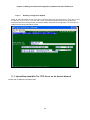
SETTING UP FIRMWARE/CONFIGURATION UP/DOWNLOAD WITH TFTP SERVER ....................... 1
17.1
OVERVIEW ......................................................................................................................................... 1
17.2
UPLOAD/DOWNLOAD WITH THE TFTP SERVER ON THE LAN SIDE ........................................................ 1
17.2.1
Step by Step Setup Instructions .............................................................................................. 1
17.2.1.1 File Transfer ........................................................................................................................ 1
17.2.1.2 Firmware Download ............................................................................................................ 1
17.2.1.3 Configuration Download...................................................................................................... 1
17.2.1.4 Startup Configuration Upload.............................................................................................. 1
17.2.1.5 Working Configuration Upload ............................................................................................ 1
17.3
UPLOAD/DOWNLOAD WITH THE TFTP SERVER ON AN OUTSIDE NETWORK ........................................... 1
18
APPENDIX A: OPERATION COMMANDS............................................................................................... 1
18.1
18.2
18.3
PING COMMAND ................................................................................................................................. 1
TRACEROUTE COMMANDS................................................................................................................... 1
BRIDGE COMMANDS ........................................................................................................................... 1
ii
18.4
18.5
18.6
18.7
18.8
18.9
18.10
DHCP COMMANDS ............................................................................................................................. 1
INTERFACE COMMANDS ...................................................................................................................... 1
NAT COMMANDS ................................................................................................................................ 1
POLICY COMMAND .............................................................................................................................. 1
ROUTE COMMANDS ............................................................................................................................ 1
SHOW COMMANDS ............................................................................................................................. 1
SYSTEM COMMAND............................................................................................................................. 1
COMMAND LIST ............................................................................................................................................... 1
19
APPENDIX B: CONVERTING A SUBNET MASK TO BINARY CODE................................................... 1
20
APPENDIX C: ROUTER-ACTIVATION PROCEDURE............................................................................ 1
GLOSSARY ....................................................................................................................................................... 1
iii
LIST OF FIGURES
Figure 1- 1 Application Diagram ------------------------------------------------------------------------------ 1
Figure 2- 1 Router-B Card Front Panel -------------------------------------------------------------------- 1
Figure 3- 1 VT-100 Monitor Connection -------------------------------------------------------------------- 1
Figure 4- 1 MLPPP Application -------------------------------------------------------------------------------- 1
Figure 6- 1 Frame Relay Application ------------------------------------------------------------------------ 1
Figure 7- 1 IP Routing Setup ---------------------------------------------------------------------------------- 1
Figure 8- 1 Router Setup (OSPF) ---------------------------------------------------------------------------- 1
Figure 9- 1 DHCP Application--------------------------------------------------------------------------------- 1
Figure 9- 2 DHCP Relay Setup ------------------------------------------------------------------------------- 1
Figure 10- 1 Setting Up IP Routing with Network Address Translation ----------------------------- 1
Figure 11- 1 Port Forwarding - Virtual Service Application -------------------------------------------- 1
Figure 12- 1 Traffic Filtering Example Network ----------------------------------------------------------- 1
Figure 13- 1 QoS Application --------------------------------------------------------------------------------- 1
Figure 14- 1 Remote bridge mode Setup ------------------------------------------------------------------ 1
Figure 15- 1 Normal RSTP Link ------------------------------------------------------------------------------ 1
Figure 15- 2 Restored RSTP Link---------------------------------------------------------------------------- 1
Figure 16- 1 VLAN Application #1---------------------------------------------------------------------------- 1
Figure 16- 2 VLAN Application #2---------------------------------------------------------------------------- 1
Figure 17- 1 Firmware/Configuration Up/Download with TFTP Server on LAN Side------------ 1
Figure 20- 2 VT-100 Terminal--------------------------------------------------------------------------------- 1
LIST OF TABLES
Table 2- 1 RJ45 10/100M Ethernet Connector Pin Assignment ------------------------------------- 1
Table 3- 1 VT-100 Monitor Parameters Default Setting ------------------------------------------------- 1
Table 3- 2 Front Panel LED Indication----------------------------------------------------------------------- 1
Table 3- 3 Front Panel Active LED Indication ------------------------------------------------------------- 1
Table 15- 1 Transit and transmission delays -------------------------------------------------------------- 1
Table 15- 2 (Rapid) Spanning Tree algorithm timer values -------------------------------------------- 1
Table 15- 3 Bridge and port priority parameter values -------------------------------------------------- 1
Table 16- 1 VLAN Table---------------------------------------------------------------------------------------- 1
Table 16- 2 VLAN Port------------------------------------------------------------------------------------------- 1
Table 19- 1 Subnet mask and prefix length conversion ------------------------------------------------ 1
iv
D
GB
F
ES
P
Bitte führen Sie das Gerät am Ende seinerLewbensdauer den zue Verfügung
stehended Rückgabeund Sammelsystemen zu.
At the end of the product's useful life, please dispose of it at appropriate collection
points provided in your country
Une fois le produit en fin devie, veuillez le déposer dans un point de recyclage
approprié.
Para preservar el medio ambiente, al final dela vida útil de su producto, depositelo
en los laguares destinado aello de acuerdo con la legislación vigente.
No final de vida útil do producto, por favor coloque no ponto de recolha apropriado.
I
Onde tutelare l'ambiente, non buttate l'apparecchio trai i normali rifiuti al termine
della sua vita utile, ma portatelo presso i punti do taccolta specifici per questi rifiuti
previsti dalla normativa vigente.
NL
Wij raden u aan het apparant aan het einde van zijn nuttige levensduur, niet bij hey
gewone huisafval te deponeren, maar op de dearvoor bestemde adressen.
DK
Når produktet er udtjent, bor det børtskaffes via de sæ rlige indsamlingssteder i
landet.
N
Ved slutten av produktets levetid bør det avhendes på en kommunal miljøstasjon
eller leveres til en elektroforhandler.
S
Lämna vänligen in produkten på lämplig återvinningsstation när den är förbrukad.
FIN
Hävitä tuote käytöiän päättyessä viemällä se asianmukaiseen keräyspisteeseen.
PL
Gdy produkt nie nadaje sie juz do dalszego uzytku, nalezy zostawic go w jednym ze
specjalnych punktów zajmujacych sie zbiórka zuzytych producktów w wybranych
miejscach na terenie kraju.
CZ
Po skončení jeho životnosti odložte prosím výrobek na přislušném sbĕrném místé
zřízeném dle předpisů ve vaší zemi.
SK
Po skončení jeho životnosti odovzdajte prosím zariadenie na príslušnom zbernom
mieste podía platných miestnych predpisov a noriem.
SLO
Ko se izdelku izteče življenska doba, ga odnesite na ustrezno zbirno mesto oziroma
ga odvrzite v skladu z veljavnimi predpisi.
GR
Στο Тέλος тης λειτουργικής Ζωής του προϊόντος παρακαλώ
Πετξτε το στα ειōικά σημεία που Παρέχονται οτη χωρα σας.
PRC
當產品使用壽命結束,請在你的國家所提供的適當地點做好回收處理
v
Chapter 1 Product Description
1 Product Description
1.1 Description
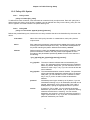
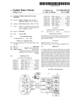
Loop Telecom’s Router-B card is designed for the Loop-AM3440 series. It occupies one regular slot of the
Loop-AM3440. When used within the Loop-AM3440, this card combines the function of a router and directs
Ethernet traffic to/from multiple WAN channels. With this card, access from LAN to WAN is accomplished
within one card, resulting in savings in cost and in space.
1
Chapter 1 Product Description
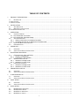
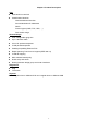
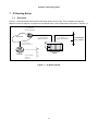
1.2 Application
Application A: As a Router
WAN
WAN
E1/ T1
E1/ T1
Loop-AM3440
Router-B
1
8
LAN 8
LAN 1
Application B: As an Inband Management Element
Loop-AM3440
Router -B
E1/T1
LAN
Network
Element
WAN
Network
Management
Workstation
Application C: As a LAN Bridge
LAN
Bridge
LAN
Loop-AM3440
E1/T1
WAN
Loop-AM3440
E1/T1
Bridge
Router-B
Router-B
Figure 1- 1 Application Diagram
2
Chapter 1 Product Description
1.3 Specifications
WAN Interface
z
Up to 64 WAN ports
z
Each WAN port has data rate nX64K bps, 1≤ n ≤32
z
The total bandwidth of all 64 WAN ports is up to 8Mbps
z
Layer-two protocol: HDLC, PPP/MLPPP, Frame Relay, Cisco compatible HDLC
z
Up to 64 Frame Relay PVCs
z
Each interface can be configured as a bridge port or router port
LAN Interface
z
Eight 10/100BaseT interfaces
z
Auto MDI/MDI-X crossover
z
Speed auto-sensing
z
Half/full duplex auto-negotiation
z
Speed/duplex force mode
z
Compliant to IEEE 802.3u
z
One RJ45 connector per Ethernet port
z
Each interface can be configured as a bridge port or router port
Router
z
Routing protocol: RIP-I, RIP-II, OSPF
z
Static route
Address Translation
z
NAT/NAPT
z
Static address table for NAT
z
Port forwarding table for NAPT (Virtual Service)
DHCP
z
DHCP server support for LAN users (RFC2131, RFC2132)
z
BOOTP compatible
z
DHCP relay
Access Control and Firewall
z
Policy based on
Inbound/outbound direction
Source/destination IP addresses
Protocol types (ICMP, TCP, UDP, …)
Port number range
z
Up to 64 control lists
3
Chapter 1 Product Description
QoS
z
QoS based on rate limit
z
Classification based on
Inbound/outbound direction
Source/destination IP addresses
DSCP
Protocol types (ICMP, TCP, UDP, …)
Port number range
Remote Bridge
z
User configurable aging time
z
Up to 16K MAC table
z
Cisco ISL packet transparent
z
VLAN packet transparent
z
Padding/un-padding Ethernet FCS
z
Rapid Spanning Tree Protocol support (IEEE 802.1w)
z
VLAN-ID mapping
z
MAC address based policy
z
DHCP relay and server
z
Routing between bridge group and router interfaces
Diagnostics
z
Ping
z
Traceroute
Physical
z
12 regular slots on AM3440-CHA and 3 regular slots on AM3440-CHB
4
Chapter 2 Installation
2 Installation
2.1 Site Selection
The following list indicates a site selection guideline. Users need to follow this guideline to select a proper
installation site.
z
z
Location of the Rack should be part of the central office equipment layout design. Considerations
should be given to entrance cable routing and -48 Vdc power.
The installation site should have -48 Vdc power. An optional AC/DC power converter can be used. Use
Only with Class 2 power source, -48 Vdc, 100 watts.
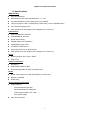
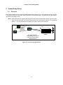
2.2 Mechanical Installation
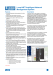
The Router-B card is designed to be plugged into any of the available slots from 1 to 12 in the Loop-AM3440
devices. The front panel is shown in the following figure.
Figure 2- 1 Router-B Card Front Panel
5
Chapter 2 Installation
2.3 Ethernet Connection
RJ45 10/100M Ethernet connection pin assignents are listed in Table 2-1 below.
Table 2- 1 RJ45 10/100M Ethernet Connector Pin Assignment
Pin Number
1
2
3
4
5
6
7
8
Signal
Transmit Data +
Transmit Data Receive Data +
No Connection
No Connection
Receive Data No Connection
No Connection
Note: The Ethernet interface supports Auto MDI/MDI-X and will work with either a parallel or a
crossover cable.
6
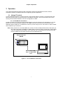
Chapter 3 Operation
3 Operation
This chapter describes the Router-B card configuration options and operational functions. Refer to
subsequent chapters for detailed instructions regarding specific applications.
3.1 Using A Terminal
To use the RS232 interface to configure the unit, use a straight cable to connect a VT100 terminal to the
DB-9 jack (Console Port) on the front panel of the AM3440 controller. The VT100 terminal can be a PC
running VT100 emulator software. The unit is configured as a DCE.
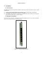
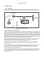
3.1.1 VT-100 Monitor Connection
In order to properly set up the set up the Router-B plug-in card you will need a VT-100 Monitor. A VT-100
Monitor is a PC running emulator software. Use a DB-9 cable to connect the front Console Port of the
AM3440 to either COM Port 1or COM Port 2 of the PC you are using as a VT-100 monitor. It doesn’t matter
which COM Port you connect to.
Note: Many newer PCs come with USB Ports. If user’s PC has a USB port rather than COM ports you
will need to purchase a available PC USB to DB-9 conversion cable commercially. These cables
come with software which loaded in a PC, allow the user to send keyboard commands through
the PC’s USB Port to the DB-9 Console Port of the Router-B card.
Router-B Card for
AM3440
CC
PP
UU
1
2 3
4
5
6
7
8
9
1
0
1
1
1
2
12
DB- 9 to PC's COM
Port or Laptop USB
Port
Figure 3- 1 VT-100 Monitor Connection
7
Chapter 3 Operation
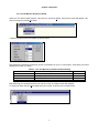
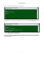
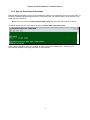
3.1.2 VT-100 Monitor Serial Port Setup
Open your VT-100 emulator program. Left-click your mouse on Setup. A drop-down menu will appear. Left
click your mouse on Serial port Setup.
A Serial port setup screen will appear as shown below.
Set COM Port to whichever COM Port you are connected to on your VT-100 monitor. Then select your other
settings from Table 3-1 below.
Item
Baud
Data Bit
Stop Bit
Parity Bit
Table 3- 1 VT-100 Monitor Parameters Default Setting
Options
38400, 19200, 9600, 2400, 1200
8, 7 bit per byte
2, 1 bit
NONE, EVEN, ODD
Default
9600
8
1
NONE
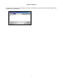
After selecting your settings left-click your mouse on OK. The setup screen will disapear.
To save your setup, left-click Save setup with your mouse, as shown in the screen bleow.
8
Chapter 3 Operation
You can save the setup in any directory you choose. For the sake of convenience we saved our setup in the
Loopterm file on our desktop.
9
Chapter 3 Operation
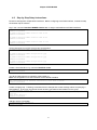
3.2 System Operation
Main menu is needed if the terminal connected to the controller. If the main menu cannot display, the user
have to set the terminal parameter to default value as Table3-1.
Press “O” to Log On, the following screen will show up.
10
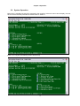
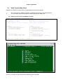
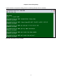
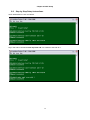
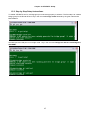
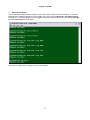
Chapter 3 Operation
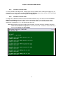
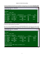
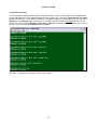
Under the Controller Menu, press “U” to select a slot for the Router-B port. Then the port menu will show as
below. In the example, the Router-B Card is installed in slot-2.
LOOP AM3440-A
=== Controller Menu ===
14:16:50 11/05/2007
Serial Number
: 1014
Hardware Version: Ver.F
Software Version: V7.01.01 11/01/2007
Redundant Controller: Enabled
Start Time : 17:56:38 11/01/2007
Device Name: LOOP AM3440-A
[DISPLAY]
C -> System Configuration
B -> Clock source Configuration
Q -> Alarm Queue Summary
I -> Information Summary
[SETUP]
S -> System Setup
M -> System Alarm Setup
W -> Firmware Transfer
V -> Store/Retrieve Configuration
K -> Clock source Setup
T -> Bit Error Rate Test
[LOG]
U -> Choose a Slot
F -> Log Off [SETUP],[MISC] Menu
O -> Log On [SETUP],[MISC] Menu
[MISC]
A -> Alarm Cut Off
X -> Clear Alarm Queue
Y -> Controller Return to Default
Z -> Controller Reset
==>> Input the unit number (A~D or 1~12): 2
Then the port menu will show as below.
Under the Port Menu, press “L” to select the command line interface. A blank screen with a flashing cursor
will appear. Key in the command “exit” to return to port menu. See section 4 for further details.
11
Chapter 3 Operation
12
Chapter 3 Operation
3.3
WAN Timeslot Map Setup
There are two steps for Router-B Card to setup WAN port’s timeslot assignment.
1.
2.
Set crossconnect on AM3440 controller. The Router-B supports up to 8 Mbps TDM bus.
CLI commands instruct the Router-B timeslot assignment for WAN ports.
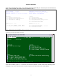
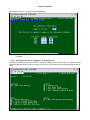
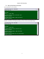
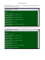
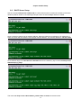
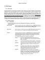
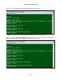
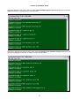
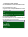
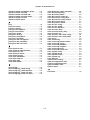
3.3.1 Setting crossconnect on AM3440 Controller.
Press “S” from Controller Menu to enter Controller Setup.
LOOP AM3440-A
=== Controller Menu ===
14:16:50 11/05/2007
Serial Number
: 1014
Hardware Version: Ver.F
Software Version: V7.01.01 11/01/2007
Redundant Controller: Enabled
Start Time : 17:56:38 11/01/2007
Device Name: LOOP AM3440-A
[DISPLAY]
C -> System Configuration
B -> Clock source Configuration
Q -> Alarm Queue Summary
I -> Information Summary
[SETUP]
S -> System Setup
M -> System Alarm Setup
W -> Firmware Transfer
V -> Store/Retrieve Configuration
K -> Clock source Setup
T -> Bit Error Rate Test
[LOG]
U -> Choose a Slot
F -> Log Off [SETUP],[MISC] Menu
O -> Log On [SETUP],[MISC] Menu
[MISC]
A -> Alarm Cut Off
X -> Clear Alarm Queue
Y -> Controller Return to Default
Z -> Controller Reset
>>SPACE bar to refresh or enter a command ===>
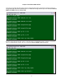
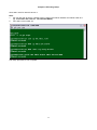
The following screen will show up in Controller Setup.
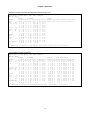
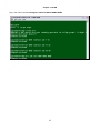
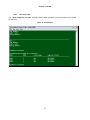
Press “C” to enter TSI map Setup and the following screen will appear.
13
Chapter 3 Operation
LOOP AM3440-A
=== System Setup (MAP) ===
11:41:41 09/13/2007
ARROW KEYS: CURSOR MOVE, TAB: ROLL OPTIONS
MAP NO: MAP_1
Target
OCT-RTB
Source
Target
PO/TS D SL/PO TS PO/TS D SL/PO TS PO/TS D SL/PO TS PO/TS D SL/PO TS
Slot : 2 ===== ========== ===== ========== ===== ========== ===== ==========
Port : P1
1 d
17 d
T.S. : 01
2 d
18 d
3 d
19 d
4 d
20 d
T.S.# : 01
5 d
21 d
Clear : No
6 d
22 d
d/v
: d
7 d
23 d
8 d
24 d
9 d
25 d
Source
10 d
26 d
Slot :
11 d
27 d
Port :
12 d
28 d
T.S. : 01
13 d
29 d
14 d
30 d
Confirm?Yes
15 d
31 d
16 d
32 d
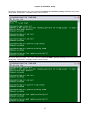
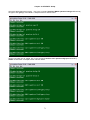
<< Press ESC to return to Controller Setup menu, then Press D to active >>
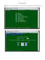
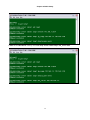
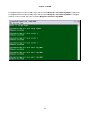
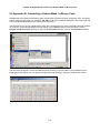
Move the cursor to Target Slot and then down to Target Port. The following screen will appear.
LOOP AM3440-A
=== System Setup (MAP) ===
11:45:05 09/13/2007
ARROW KEYS: CURSOR MOVE, TAB: ROLL OPTIONS
MAP NO: MAP_1
Target
OCT-RTB
Source
Target
PO/TS D SL/PO TS PO/TS D SL/PO TS PO/TS D SL/PO TS PO/TS D SL/PO TS
Slot : 2 ===== ========== ===== ========== ===== ========== ===== ==========
Port : P1
1 1 d 4 1 1 1 17 d 4 1 17
T.S. : 01
1 2 d 4 1 2 1 18 d 4 1 18
1 3 d 4 1 3 1 19 d 4 1 19
1 4 d 4 1 4 1 20 d 4 1 20
T.S.# : 01
1 5 d 4 1 5 1 21 d 4 1 21
Clear : No
1 6 d 4 1 6 1 22 d 4 1 22
d/v
: d
1 7 d 4 1 7 1 23 d 4 1 23
1 8 d 4 1 8 1 24 d 4 1 24
1 9 d 4 1 9 1 25 d 4 1 25
Source
1 10 d 4 1 10 1 26 d 4 1 26
Slot : 4
1 11 d 4 1 11 1 27 d 4 1 27
Port :
1 12 d 4 1 12 1 28 d 4 1 28
T.S. : 01
1 13 d 4 1 13 1 29 d 4 1 29
1 14 d 4 1 14 1 30 d 4 1 30
Confirm?Yes 1 15 d 4 1 15 1 31 d 4 1 31
1 16 d 4 1 16
32 d
<< Press ESC to return to Controller Setup menu, then Press D to active >>
14
Chapter 3 Operation
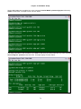
Move the cursor to Source Slot and then down to Source Port.
LOOP AM3440-A
=== System Setup (MAP) ===
11:46:37 09/13/2007
ARROW KEYS: CURSOR MOVE, TAB: ROLL OPTIONS
MAP NO: MAP_1
Target
OCT-RTB
Source
Target
PO/TS D SL/PO TS PO/TS D SL/PO TS PO/TS D SL/PO TS PO/TS D SL/PO TS
Slot : 2 ===== ========== ===== ========== ===== ========== ===== ==========
Port : P1
1 1 d 4 1 1 1 17 d 4 1 17
T.S. : 01
1 2 d 4 1 2 1 18 d 4 1 18
1 3 d 4 1 3 1 19 d 4 1 19
1 4 d 4 1 4 1 20 d 4 1 20
T.S.# : 01
1 5 d 4 1 5 1 21 d 4 1 21
Clear : No
1 6 d 4 1 6 1 22 d 4 1 22
d/v
: d
1 7 d 4 1 7 1 23 d 4 1 23
1 8 d 4 1 8 1 24 d 4 1 24
1 9 d 4 1 9 1 25 d 4 1 25
Source
1 10 d 4 1 10 1 26 d 4 1 26
Slot :
1 11 d 4 1 11 1 27 d 4 1 27
Port :
1 12 d 4 1 12 1 28 d 4 1 28
T.S. : 01
1 13 d 4 1 13 1 29 d 4 1 29
1 14 d 4 1 14 1 30 d 4 1 30
Confirm?Yes 1 15 d 4 1 15 1 31 d 4 1 31
1 16 d 4 1 16
32 d
<< Press ESC to return to Controller Setup menu, then Press D to active >>
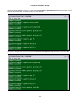
The following screen will appear.
LOOP AM3440-A
=== System Setup (MAP) ===
11:46:37 09/13/2007
ARROW KEYS: CURSOR MOVE, TAB: ROLL OPTIONS
MAP NO: MAP_1
Target
OCT-RTB
Source
Quad-E1 NON-CAS
Target
PO/TS D SL/PO TS PO/TS D SL/PO TS PO/TS D SL/PO TS PO/TS D SL/PO TS
Slot : 2 ===== ========== ===== ========== ===== ========== ===== ==========
Port : P1
1 1 d 4 1 1 1 17 d 4 1 17
1 1 d 2 1 1 1 17 d 2 1 17
T.S. : 01
1 2 d 4 1 2 1 18 d 4 1 18
1 2 d 2 1 2 1 18 d 2 1 18
1 3 d 4 1 3 1 19 d 4 1 19
1 3 d 2 1 3 1 19 d 2 1 19
1 4 d 4 1 4 1 20 d 4 1 20
1 4 d 2 1 4 1 20 d 2 1 20
T.S.# : 31
1 5 d 4 1 5 1 21 d 4 1 21
1 5 d 2 1 5 1 21 d 2 1 21
Clear : No
1 6 d 4 1 6 1 22 d 4 1 22
1 6 d 2 1 6 1 22 d 2 1 22
d/v
: d
1 7 d 4 1 7 1 23 d 4 1 23
1 7 d 2 1 7 1 23 d 2 1 23
1 8 d 4 1 8 1 24 d 4 1 24
1 8 d 2 1 8 1 24 d 2 1 24
1 9 d 4 1 9 1 25 d 4 1 25
1 9 d 2 1 9 1 25 d 2 1 25
Source
1 10 d 4 1 10 1 26 d 4 1 26
1 10 d 2 1 10 1 26 d 2 1 26
Slot : 4
1 11 d 4 1 11 1 27 d 4 1 27
1 11 d 2 1 11 1 27 d 2 1 27
Port : P1
1 12 d 4 1 12 1 28 d 4 1 28
1 12 d 2 1 12 1 28 d 2 1 28
T.S. : 01
1 13 d 4 1 13 1 29 d 4 1 29
1 13 d 2 1 13 1 29 d 2 1 29
1 14 d 4 1 14 1 30 d 4 1 30
1 14 d 2 1 14 1 30 d 2 1 30
Confirm?Yes 1 15 d 4 1 15 1 31 d 4 1 31
1 15 d 2 1 15 1 31 d 2 1 31
1 16 d 4 1 16
32 d
1 16 d 2 1 16
<< Press ESC to return to Controller Setup menu, then Press D to active >>
15
Chapter 3 Operation
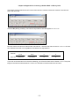
Press ESC to return to Controller Setup Menu. Press “D” from Controller Setup and go to Select a new TSI
map.
The following screen will appear.
16
Chapter 3 Operation
Press ESC and press “Y” to activate TSI MAP setting.
Note: Router-B Card and Quad-E1 card do the MAP setting in Port 1. Now the MAP setting is now
complete.
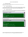
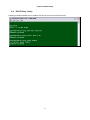
3.3.2 Assigning timeslots for a WAN port on Router-B card.
After the user setup the AM3440 TSI MAP in main board, please go to Router-B card’s Port Menu to select
Router-B Card and set the timeslot in order for the user to crossconnect the Controller card with Router-B
card.
17
Chapter 3 Operation
Press “L” from Port Menu and go to Command Line screen.
A blank screen with a flashing cursor will appear. Key in the command interface WAN1 timeslot set 132.
3.3 Effecting New Configuration
All changes of Router-B card configuration take effect imediately except for the following feature: system
activate routing and configuration download. The feature take effect after the unit is powered down and
then powered up again.
18
Chapter 3 Operation
3.4 LED Operation
The front panel of the Router-B has two LEDs for each LAN port They are for: Ethernet Link/Active, and
Ethernet speed. LED Indications are listed in Table 3-2, below.
LED
L
A
N
LINK/ ACT
10/100
LED
Active LED
Table 3- 2 Front Panel LED Indication
Indication
Off
No Ethernet connection or Link fail
Green
Link
Flashing Green
Active
Off
10Mbps
Green
100Mbps
Color
Table 3- 3 Front Panel Active LED Indication
Color
Indication
Off
Power Off
Green
System is functioning
Amber
Power on self test
19
Chapter 4 PPP/MLPPP
4 PPP/MLPPP
4.1
Overview
Multilink PPP can connect multiple links between two systems as needed to provide extra bandwidth.
Remotely accessing resources through PPP Multilink allows for the increase in overall throughput by
combining the bandwidth of two or more physical communication links.
Example: To bundle the four WAN interfaces (WAN1~WAN4) in a virtual interface(m1) and make the virtual
interface become bridge mode. When the data packets transmit from LAN to bundle interface, MLPPP will
split and recombine the packets and transmit to WAN1~WAN4.
Figure 4- 1 MLPPP Application
20
Chapter 4 PPP/MLPPP
4.2
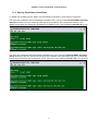
Step by Step Setup Instructions
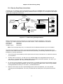
Router B card supports multiple WAN interfaces. Before configuring each WAN interface, it needs to setup
the timeslot map in advance.
Key in the command interface WANXX timeslot set to assgin 128 timeslots to all WAN interfaces.
[2]admin>interface WAN1 timeslot add 1-32
Command succeeded
[2]admin>interface WAN2 timeslot add 33-64
Command succeeded
[2]admin>interface WAN3 timeslot add 65-95
Command succeeded
[2]admin>interface WAN4 timeslot add 97-128
Command succeeded
Set the interfaces to use PPP for layer-two encapsulation.
[2]admin>interface WAN1 encapsulation ppp
Command succeeded
[2]admin>interface WAN2 encapsulation ppp
Command succeeded
[2]admin>interface WAN3 encapsulation ppp
Command succeeded
[2]admin>interface WAN4 encapsulation ppp
Command succeeded
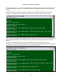
Create a virtual bundle m1 by command multilink create.
[2]admin>multilink create m1
Command succeeded
Join all the WAN ports to be members of the bundle m1.
Note: the configuration on those interfaces will be cleared to default.
[2]admin>multilink virtual m1 add WAN1 WAN2 WAN3 WAN4
The configurations of bundled interface(s) have been cleared!
Command succeeded
Create a bridge group. Following command show an example that creates a bridge without a specifying a
MAC address. In the case, the Router B card randomly generates a MAC address for the group.
[2]admin>bridge create br1
WARNING: A MAC address has been randomly generated for bridge group!
conflict
with other device!!
Command succeeded
Add lan1 and m1 into bridge.
[2]admin>bridge br1 add lan1 m1
Command succeeded
21
It might
Chapter 5 ROUTER-B CARD SETUP
5 ROUTER-B CARD SETUP
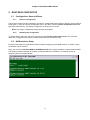
5.1
Configuration -Save and Reset
5.1.1
Save the configuration
The Router-B card stores all configuration changes in volatile RAM. After the device reboots, all the changes
will be gone. In order to save this configuration, key in the admin comand system configuration save and
then press the Enter key. The startup configuration is stored as a CLI script.
Note: The shartup configuration saving space is about 895K.
5.1.2
Resetting the Configuraton
To restore factory settings in the future use the command system configuration reset. The command
resets the configuration to the factory default setting and then reboots the card.
5.2
WAN Interface Setup
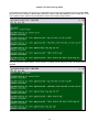
Router-B card supports mutiple WAN interfaces. Before configuring each WAN interface, it needs to setup
the timeslot map in advance.
Key in the command interface WAN1 and WAN2 timeslot set to assgin timeslots to WAN interface WAN1.
The following example assigns 32 timeslots to interface WAN1 from timeslot 1 to timeslot 32 and 32
timeslots (33-64) to interface WAN2.
22
Chapter 5 ROUTER-B CARD SETUP
The following example shows how to configure the encapsulation PPP on interface WAN1 and WAN2.
Note: make sure to follow the above setup step, otherwise the internet cannot work properly.
The above settings are the basic settings for a valid WAN interface.
An interface can be in either router mode or bridge mode, the following sections show how to set the
interface to router mode and bridge mode.
23
Chapter 5 ROUTER-B CARD SETUP
5.2.1
Interfaces in bridge mode
To set any interfaces to bridge mode, a bridge group must be created. After creating the bridge group, for
example br1, key in the admin command bridge br1 add WAN1 and press the enter key. Then the WANxx
interface will be in bridge mode and belong to the bridge group br1.
5.2.2
Interfaces in router mode
To assign an IP address and subnet mask to the WAN interfaces, key in the admin command interface
WAN1 ip and WAN2 ip followed by the IP address and subnet mask. In the following screen below,
interface wan1 is assigned an IP address 10.1.1.1 with subnet mask 255.0.0.0 and interface wan2 is
assigned an IP address 20.1.1.1 with subnet mask 255.0.0.0.
Note: WAN interface could be in bridge mode as default. The user can key in the admin command
show interface WAN1 configuration to check current mode. To switch to router mode, key in
the command bridge xxx delete WAN1.
24
Chapter 5 ROUTER-B CARD SETUP
The users may enable the RIP routing protocol to allow Router-B card automatically exchange dynamical
routing tables with other RIP-enabled routers. To enable RIP routing protocol, key in the command interface
WAN1 and WAN2 route rip setup enable.
Router-B card supports both RIP version 1 and RIP version 2. The default version is version 2 in Router-B
card. To change the RIP version, key in the command interface WAN2 route rip version.
25
Chapter 5 ROUTER-B CARD SETUP
5.3
LAN interface Setup
An interface can be either in router mode or bridge mode, the following sections shows how to set the
interface to router mode and bridge mode.
5.3.1
Interfaces in bridge mode
To set any interfaces to bridge mode, a bridge group must be created. Please refer to Chapter 14 for details.
After creating the bridge group, for example br1, key in the admin command bridge br1 add lan1 and press
the enter key. Then the LAN1 interface will be in bridge mode and belong to the bridge group br1.
5.3.2
Interfaces in router mode
To assign an IP address and subnet mask to the LAN interfaces, key in the admin command interface lan1
ip followed by the IP address and subnet mask. In the following screen below interface lan1 is assigned with
IP address 192.168.1.254 with subnetmask 255.255.255.0.
The users may enable the RIP routing protocol to allow Router-B card automatically exchange dynamical
routing tables with other RIP-enabled routers. To enable RIP routing protocol, key in the command interface
lan1 route rip setup enable.
Router-B card supports both RIP version 1 and RIP version 2. The default version in Router-B card is
version 2. To change the RIP version, key in the command interface lan1 route rip version.
26
Chapter 5 ROUTER-B CARD SETUP
27
Chapter 6 Frame Relay Setup
6 Frame Relay Setup
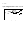
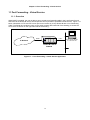
6.1
Overview
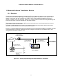
Each Router-B WAN port can support multiple Frame Relay PVCs up to 16. The maximum number of PVCs
in a Router-B card is 64. Figure 6-1, below, illustrates a Frame Relay setup. The dashed lines in the diagram
represent Frame Relay PVCs.
Note: Router-B cards only support user site protocol and cannot communicate directly with each other.
They must be connected to a Frame Relay network that includes devices that run on FR network
protocol. The Loop-AM3440 Frame Relay card can be used as such a device.
User
Frame
Relay
Network
The Loop-AM 3440
Frame Relay card can be
used as a Frame Relay
network device.
Figure 6- 1 Frame Relay Application
28
Router-B card for
AM3440
Chapter 6 Frame Relay Setup
6.2
Step by Step Setup Instructions
Set the WAN port to run Frame Relay.
Set Frame Relay polling protocol as Q.933 Annex A and its parameters n391, n392, n393, and t391. Please
note that these parameters must match the parameters on the network side.
29
Chapter 6 Frame Relay Setup
Then create a PVC and set its bandwidth parameters.
Note: In the above screen the first 512 is the value for the CIR (Committed Information Rate in Kbps)
of PVC1. The total sum of the CIR values for all PVCs must not exceed the total physical
bandwidth of the WAN port. Physical bandwidth can be calculated by using the formula.
Physical bandwidth= n (Where n represents number of timeslots assigned for the WAN port) x 64k.
If you are not sure how many timeslots you used in your WAN port mapping, you can check by using
the command show timeslot.
Assign an IP address for the PVC.
30
Chapter 6 Frame Relay Setup
A PVC can also run a dynamic routing protocol. In following example, RIP II is enabled.
This setup procedure is now complete.
31
Chapter 7 IP Routing Setup
7 IP Routing Setup
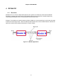
7.1
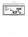
Overview
Figure 7-1 below illustrates the Router-B card being used in router mode. The IP address and gateway
address used in the diagram correspond to the sample step by step configuration instructions in Section 7.2.
Peer Router
IP 100.2.254.253
WAN 1
IP: 100.2.254.254
MASK: 255.255.0.0
IP Network
IP: 160.2.254.253
Gateway: 255.255.0.0
LAN 1
IP: 192.168.1.1
MASK: 255.255.255.0
1
2
3
4
5
6
7
8
9
1
0
C C
P P
U U
1 2
Router-B card for
AM3440
IP Router
Network Address
100.3.0.0
255.255.0.0
Figure 7- 1 IP Routing Setup
32
1
1
1
2
Local Network
with IP Address
Chapter 7 IP Routing Setup
7.2
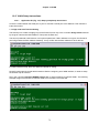
Step by Step Setup Instructions
Set IP addresses for LAN1 and WAN1.
In example, we disable routing protocol. If the RIP 1 or RIP 2 protocol are used, the setup procedure is
complete. If RIP protocol is not supported by the peer router, the user must use static routing.
33
Chapter 7 IP Routing Setup
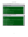
Set a static route for network 100.3.0.0.
Note:
1.
the user are able to specify a default route by setting the network address and subnet mask as 0
(eg. route static add 0.0.0.0/0. 100.2.254.253 WAN1).
2.
max static route number: 64
This setup procedure is now complete.
34
Chapter 8 OSPF Setup
8 OSPF Setup
8.1
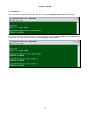
Overview
Figure 8-1 below illustrates the Router-B card being used in router mode. The IP address and gateway
address used in the diagram correspond to the sample step by step configuration instructions in Section 8.2.
Peer Router
IP 100.2.254.253
WAN 1
IP: 100.2.254.254
MASK: 255.255.0.0
IP Network
IP: 160.2.254.253
Gateway: 255.255.0.0
LAN 1
IP: 192.168.1.1
MASK: 255.255.255.0
1
2
3
4
5
6
7
8
9
1
0
1
1
Local Network
with IP Address
1
2
C C
P P
U U
1 2
Router-B card for
AM3440
IP Router
Network Address
100.3.0.0
255.255.0.0
Figure 8- 1 Router Setup (OSPF)
Open Shortest Path First Protocol (OSPFv2)
OSPF is an interior gateway protocol used for routing between routers belonging to a single Autonomous
System. OSPF uses link-state technology in which routers send each other information about the direct
connections and links which they have to other routers. Each OSPF router maintains an identical database
describing the Autonomous System's topology. From this database, a routing table is calculated by
constructing a shortest- path tree. OSPF recalculates routes quickly in the face of topological changes,
utilizing a minimum of routing protocol traffic. OSPF provides support for equal-cost multi-path. An area
routing capability is provided, enabling an additional level of routing protection and a reduction in routing
protocol traffic. In addition, all OSPF routing protocol exchanges are authenticated.
OSPF has been designed expressly for the TCP/IP internet environment, including explicit support for CIDR
and the tagging of externally-derived routing information. OSPF also provides for the authentication of
routing updates, and utilizes IP multicast when sending/receiving the updates.
OSPF routes IP packets based solely on the destination IP address found in the IP packet header. IP
packets are routed "as is" - they are not encapsulated in any further protocol headers as they transit the
Autonomous System.
OSPF allows sets of networks to be grouped together. Such a grouping is called an area. The topology of an
area is hidden from the rest of the Autonomous System. This information hiding enables a significant
reduction in routing traffic. Also, routing within the area is determined only by the area's own topology,
lending the area protection from bad routing data.
OSPF enables the flexible configuration of IP subnets. Each route distributed by OSPF has a destination and
mask. Two different subnets of the same IP network number may have different sizes (i.e., different masks).
This is commonly referred to as variable length subnetting. A packet is routed to the best (i.e., longest or
most specific) match.
35
Chapter 8 OSPF Setup
8.2
Step by Step Setup Instructions
Set IP addresses for LAN1 and WAN1.
Key in the admin command route ospf area add 1 to create an area with ID 1.
36
Chapter 8 OSPF Setup
Set up the WAN1 interface. Key in the admin command interface wan1 route ospf setup enable 1 to add
WAN1 into area 1. Then press the Enter key.
Save the configuration. Key in the command system configuration save. Then press the Enter key.
This setup procedure is now complete.
37
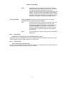
Chapter 9 DHCP Setup
9 DHCP Setup
9.1
DHCP Server overview
DHCP (Dynamic Host Configuration Protocol) can be used to automatically assign IP addresses, to deliver
TCP/IP stack configuration parameters (ie. subnet mask and default router), and to provide other
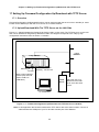
configuration information. Figure 9-1, below, illustrates the Router-B card set up in a DHCP server
application. All hosts (shown on the right hand side of the network diagram) can get IP addresses from the
Router-B card when its DHCP Server is enabled.
Router-B Card for
AM3440
1
WAN1
IP Network
2
3
4
5
6
7
8
9
1
0
1
1
1
2
CC
PP
UU
LAN1
Host (DHCPClient)
12
Network Address: 192.168.1.0
Subnet Mask : 255.255.255.0
Host (DHCPClient)
..........
Figure 9- 1 DHCP Application
38
Chapter 9 DHCP Setup
9.2
DHCP Server Setup
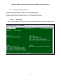
Use the command dhcp server subnet add to create a subnet which contains all necessary information
needed by DHCP clients. In the following example screen the subnet loop1 had been created.
Once a subnet is created, we set network address. When the DHCP server allocate an IP address for a
client, the server will also send the client proper network address. The network address is 192.168.1.0/24.
An IP address range from 192.168.1.5 to 192.168.1.20 is for the subnet by key in command dhcp server
subnet loop1 ip_range.
The command dhcp server subnet domain_name works set works for domain name.
39
Chapter 9 DHCP Setup
A DNS server 192.168.1.2 is set by command dhcp server subnet loop1 dns_server add.
40
Chapter 9 DHCP Setup
To use command dhcp server interface add to add all LAN interfaces which offer DHCP service. As
following example, only the LAN1 is enabled for the service.
The command dhcp server enables the DHCP service.
When the DHCP server is running, the hosts on network connected to LAN1 can use the DHCP to obtain IP
addresses.
41
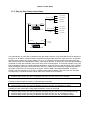
Chapter 9 DHCP Setup
9.3
DHCP Relay Overview
Deploying DHCP in a single subnet network is straightforward. DHCP messages are IP broadcast
messages, and all computers on the subnet can listen to and respond to these broadcasts. A single DHCP
server is all that is required.
It is complicated when there is more than one subnet on your network. This is because the DHCP broadcast
messages do not (by default) cross the router interfaces. The DHCP relay agent allows you to place DHCP
clients and DHCP servers on different subnets of your network or even to put them on different networks.
Router-B card for
AM3440
IP Network
WAN1
CC 1
PP
UU
2 3
4
5 6 7 8 9
1
0
1 1
1 2
LAN1
Host (DHCP Client)
12
DHCP Server
10.3.2.10
DHCP Relay Server
Host (DHCP Client)
..........
Figure 9- 2 DHCP Relay Setup
42
Chapter 9 DHCP Setup
9.4
DHCP Relay Setup
Following example illustrate how to enable a DHCP relay service in the Router-B card.
43
Chapter 10 Network Address Translation Service
10 Network Address Translation Service
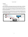
10.1 Overview
The Router-B card Network Address Translation (NAT) service allows IP clients on your local network to
access the Internet without requiring you to assign globally unique IP addresses to each system. This
feature is used when the user's network only needs to have a few addresses available to access the
Internet. In addition, NAT acts as a filter, allowing only certain outbound connections and guaranteeing that
inbound connections cannot be initiated from the public network.
This chapter will describe how to setup NAT service to allow clients on your private network to access a
public network, such as the Internet.
In Chapter 11 will describe how to setup port fordwarding (virtual service) to allow clients on the public
network to access selected resources on your private network.
Figure 10-1 below illustrates the Router-B card being used to provide Network Address Translation services.
The IP addresses and gateway addresses used in the diagram correspond to the sample step by step
configuration instructions in Section 10.2.
Peer Router
IP 100.2.254.253
LAN 1 with Private IP Address
IP: 192.168.1.1
MASK: 255.255.255.0
WAN 1 with Public IP Address
IP: 100.2.254.254
MASK: 255.255.0.0
IP Network
IP: 160.2.256.253
MASK: 255.255.0.0
1
2
3
4
5
6
7
8
9
1
0
1
1
1
2
CC
PP
UU
12
Router-B interface
Card for AM3440
IP Router
Network Address
100.3.0.0
255.255.0.0
Figure 10- 1 Setting Up IP Routing with Network Address Translation
44
Local Network
with IP Address
Chapter 10 Network Address Translation Service
10.2 Step by Step Setup Instructions
Network address translation service is only available on WAN or PVC interfaces which is in router mode. To
implement network address translationservice on Router-B card, the relevant WAN or PVC interface must
setup properly in advance.
Note: Key in the command show interface XXX config and then press the Enter key to check.
To enable the service, key in the admin command interface XXX napt setup enable.
When network translation service is enabled, all routing protocols (including RIP 1 and RIP 2) are
automatically disabled. This setup procedure is now complete.
45
Chapter 11 Port Forwarding - Virtual Service
11 Port Forwarding - Virtual Service
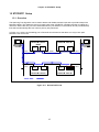
11.1 Overview
When NAPT is enabled, the user is able to set up a static port forwarding table in the Loop Router-B card
that instructs the Router-B card to forward specific service packets to specified internal servers. Figure 11-1
below, illlustrates a HTTP and FTP server put into an intranet by a Loop Router-B with a Port Forwarding
Table. The Router-B card allows users on the public network (left-hand side of the drawing) to access the
HTTP and FTP Server on the right-hand side of the drawing.
1
2
3
4
5
6
7
8
9
1
0
1
1
1
2
WAN1
LAN1
IP Network
Router-B Card for
AM3440
Figure 11- 1 Port Forwarding - Virtual Service Application
46
HTTP & FTP Server
IP 192.168.1.25
Chapter 11 Port Forwarding - Virtual Service
11.2 Step by Step Setup Instructions
To enable port forwrding service, NAPT must be enabled in the WAN or PVC interface in advance.
The user have to establish where http packets forwarded. Key in the command interface WAN1 napt static
add http followed by the port number and the http server ip address. Then press the Enter key. In the
sample screen below the packets are forwarded to port 80, then key in the IP address 192.168.1.25 for http
server.
The user have to establish where ftp packets forwarded. Key in the command interface WAN1 napt static
add ftp followed by the port number and the ftp server ip address. Then press the Enter key. In the sample
screen below the packets are forwarded to port 21, then key in the IP address 192.168.1.25 of our ftp server.
47
Chapter 11 Port Forwarding - Virtual Service
To view the results of setup, key in the command show interface WAN1 nat. The setup configuration will
be displayed as the screen below.
48
Chapter 12 Traffic Filtering Setup
12 Traffic Filtering Setup
12.1 Overview
The Router-B card provides basic traffic filtering capabilities, such as access control lists (ACL). Traffic
filtering is the process of deciding the disposition of each packet that can possibly pass through a router with
the access control lists. With this feature, Router-B card provides the basic protection mechanism for a
routing firewall host, allowing the user to determine what traffic passes through it based upon the contents of
the packet, thereby potentially limiting access to each of the networks controlled by the lists.
The access control lists are a group of entries. Each entry defines a pattern that would be found in an IP
packet and associates an action with the packets. As each packet comes through an interface with an
associated access list, the list is scanned from top to bottom for a pattern that matches the incoming packet.
A permit or deny rule associated with the pattern determines that packet's disposition. The user can also use
a mask, which is like a wild card, to determine how much of an IP source or destination address to apply to
the pattern match. The pattern statement also include a TCP or UDP destination port number.
Also, keep in mind that once you associate the list with an interface, any packet not matched by the list is
dropped by default.
49
Chapter 12 Traffic Filtering Setup
12.2 Policy ACL Syntax
12.2.1
Policy create
policy acl create [list_name]
To define an access control list, user first needs to create the list by a unique name. Each ACL policy list is
referenced by this name. Once the list is created, user can add the new entry into the list by “policy acl <listname> append” command to define new packet filtering rule.
12.2.2
Policy add
policy acl <list-name> append [action] [selector]
Defines the packet filtering rule; instructs the new entry to add at the tail of the list defined by the name <listname>
<list-name>
Name of the ACL policy list which is created above, each policy list has
unique name.
action
Each statement’s parameter is started with the action field; specify packets
matching the criteria should permit or deny. This decides the disposition of
the packet matching the pattern definition described by selector.
selector
Packet matching criteria, the selector sets some matching condition. If the
packet matches the condition, then the packet will be applied an action
according to the parameters specified by action. Format of the selector is
as following:
"[src_ip/prefix] [dst_ip/prefix] [protocol] [service]"
src_ip/prefix
The source network address that are interested by the
policy. The parameter will be matched with source address
field of IP packets. With prefix, you can indicate a host or a
network to match. Key in ‘any’ if you do not want to filter the
source address.
dst_ip/prefix
The interested destination network address. The parameter
will be matched with destination address field of IP packets.
With prefix, you can indicate a host or a network to match.
Key in ‘any’ if you do not want to filter the destination
address.
protocol
Interested protocol type carried by an IP packet. If you are
interested on filtering only on IP addresses, this field can be
ignored. Otherwise if you are trying to filter TCP, UDP or
ICMP packets, specify the appropriate name of protocol.
service
If protocol is TCP or UDP, you can mention the specific
destination port number carried by an IP packet for filtering;
otherwise this field has no meaning. You can mention
destination port number in minimum-maximum format for a
range of port number or ‘any’ if you are not interested for a
particular destination port number.
50
Chapter 12 Traffic Filtering Setup
12.2.3
Policy delete
policy acl <list-name> delete [start_index] [end_index]
Instructs the policy to be deleted. Each policy is indexed by the policy number in the ACL policy list, user
should mention the policy number which one to be removed.
12.2.4
<list-name>
unique name of the ACL policy list.
start_index
Start index of the policy list. If end_index is not mentioned,
only one policy with index “start_index” will be removed
from the list.
end_index
Optional end index; if mentioned, all entries between start
and end index will be removed from the list.
Policy display
show policy <list-name>
Display all the filtering rules defined in the ACL list named “list-name”
51
Chapter 12 Traffic Filtering Setup
12.3 Adding ACL entries
Before adding any ACL entry, an ACL list must be created first. Key in the command policy acl create
followed by the name you WANt to gice. Then press the Enter key. In the following example, the list name
“list1” is given.
After creating the control list, ACL entris are able to be appended.
A screen with a flashing cursor will appear. Key in the command policy acl list-1 append followed by the
packet source IP address plus its subnet mask prefix length, the packet destination IP address (ie. your
HTTP server) plus its subnet mask prefix length, and finally the number of the port where the packet will be
received. Press the Enter key.
In our sample screen below we keyed in any as the source address, 192.168.1.11/32 as the destination
HTTP IP address, 32 as the destinatrion address subnet mask prefix length, and 80 as the port number.
52
Chapter 12 Traffic Filtering Setup
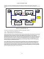
12.4 Step by Step Setup Instructions
In section12.2, an example is given to illustrates how to filter out unWANted traffic and permit certain traffic
in this situation. The IP addresses and gateway addresses used in the Figure 12-1 correspond to the sample
step by step configuration instructions.
Peer Router
IP 100.2.254.253
Company
Head Office
Customer
IP: 140.1.x.x
MASK: 255.255.0.0
IP Network
WAN 1
IP Address
IP: 100.2.254.254
MASK: 255.255.0.0
LAN 1
IP Address
IP: 192.168.1.1
MASK: 255.255.255.0
IP Router
IP: 160.2.254.253
Gateway: 255.255.0.0
Remote User
I P: 140.100.5.5
Company Branch
Network Address
100.3.0.0
255.255.0.0
Router-B Card for
AM3440
HTTP Server
IP: 192.168.11
FTP Server
IP: 192.168.22
TELNET Server
IP: 192.168.33
Figure 12- 1 Traffic Filtering Example Network
Before configuring the access control lists, you need to setup relevent interfaces in router mode.
In Figure 12-1, three servers are located in the local network. Their IP addresses are as follows:
HTTP Server:
192.168.11
FTP Server:
192.168.22
TELNET Server:
192.168.33
Note: This is a sample setup only. Your setup will have IP addresses relevant to your own situation.
Our goal in this example is to protect your local network behind the LAN1 interface but still privide some
traffic to access certain servers in the local network. More specifically, the following statements are given to
illustrates our security requirement.
1.
The HTTP server is accessible by all PCs (also known as hosts) in the network, no matter from internet
or local network.
2.
TELNET Server access (IP: 192.168.100.33) is available only to the designated Remote User (IP:
140.100.5.5 ). No other devices, including those at thecompany head office (Network: 192.168.1.0) or
branch office (Network: 100.3.0.0), can reach that server.
3.
IP: 100.3.0.0 is the network for company branch office, so all traffic from that site is permitted to access
PCs in company head office (Network: 192.168.1.0) except the TELNET server, which is only available
to designated Remote User (IP: 140.100.5.5 ), as desbribed above.
4.
Because TFTP Server Access is provided only for the custmer site (Network: 140.1.0.0) and the
company branch office(Network: 100.3.0.0), the Router-B card shall permit TFTP packets from those
sites.
53
Chapter 12 Traffic Filtering Setup
Before adding any ACL entry, an ACL list must be created first. Key in the command policy acl create
followed by the name you WANt to give. Then press the Enter key. In the following example, the list name
“list1” is given.
After creating the control list, ACL entries are able to be appended. Press the Enter key.
In the example entry shows below, any TCP packets with port number 80 is permitted to access the HTTP
server, i.e. the HTTP session to HTTP server is allowed.
In the example entry shows below, packets with source IP address 140.100.5.5, destination IP address
192.168.1.11, TCP port number 23 is permitted, i.e. the TELNET session requests from 140.100.5.5 to
192.168.1.11 are allowed.
54
Chapter 12 Traffic Filtering Setup
In the following example, one more entry is appended to the access control list list1. That entry denies all
TCP packets with port number 23, i.e. the TELNET session is prohibitted to any location on the company
network.
Combining the last two entrise, this access list accepts only the TELNET session from 140.100.5.5 to
192.168.1.11 and drops all other TELNET session currently, which meets the 2nd security request.
Key in the command policy ac1 list1 append followed by the permit action, the selector specified the packet
source IP address and binary code subnet mask with the branch office network to meet the 3rd security
request.
The entries are scanned from top to bottom when packets passing through the Router-B card.
The following command will allow any packets from a branch office to pass through to head office. However,
TELNET sessions are prohibited because the command above is appended.
55
Chapter 12 Traffic Filtering Setup
In the following example, one more entry is appended to the access control list list1.That entry allows UDP
packets with source address 140.1.0.0/16, destination address 192.168.1.22/32 and port number 69, i.e. the
TFTP sessions from custmer site are allowed to access the company branch office.
The final command, shown below, can be omitted. If a packet cannot match any rules, the packet will be
dropped.
56
Chapter 12 Traffic Filtering Setup
In case of checking the rule entries in the control list, the user can key in the command show policy XXX,
where XXX shall be the name of access control list. For example, key in the command show policy list1.
The access list will be active when it is associated with a port or interface. The ACL can be applied to
incoming or outgoing packets on the interface.
Key in the command interface XXX policy acl inbound/outbound YYY, where XXX is the interface name
and YYY is the access list name. For exmaple, key in the command where XXX is WAN1 and YYY is list1.
57
Chapter 13 QoS Setup
13 QoS Setup
13.1 Overview
In packet networks, one important requirement for link sharing is to share bandwidth on a link between
multiple agencies, where each agency wants to receive a guaranteed share of the link bandwidth during
congestion. But where bandwidth that is not being used by one agency should be available to other
agencies sharing the link. Quality of Service (QoS) is the idea that transmission rates, error rates can be
measured, improved, and to some extent guaranteed in advance. QoS enables you to provide better service
to certain flows and helps user to control the use of the outbound traffic on a given link. Router-B QoS is
policy based where the traffic type defines each policy. In AM3440, we have classified the outgoing traffic
(i.e. policy) by packet’s IP address, network protocol and/or TCP/UDP port number. User can configure the
committed bandwidth for a particular class of traffic by mentioning the minimum and maximum bandwidth.
Make sure total configured bandwidth of all such policy must not exceed the link’s physical bandwidth.
Note: QoS is supported for WAN interface only and it supports maximum 32 WAN interfaces at a time.
13.2 Policy Syntax
13.2.1
Policy add
interface wan1~64 policy qos rate_limit append/insert [policy_num] selector
action_parameter
append/insert
Instructs where to put the newly created policy entry. If append is specified,
the new entry is put at the tail of the policy list. If insert is specified, the new
entry is put before the policy number specified by policy_num.
policy-num
When the policy is inserted into the list, policy_num specifies insert point of
the new policy entry, for append user should not skip this parameter.
selector
Outgoing packet match criteria, the selector sets some matching condition.
If the packet going through the interface matches the condition, then the
packet will be applied an action according to the parameters specified by
action-parameter. Format of the selector is as following:
src_ip dest_ip protocol [src_port] [dst_port] [dscp]
src_ip
The source network address that are interested by the
policy. The parameter will be matched with source address
field of IP packets.
dst_ip
The interested destination network address. The parameter
will be matched with destination address field of IP packets.
protocol
Interested protocol type carried by an IP packet. The field
can be a decimal value or a protocol name, like TCP or
UDP.
src_port
If protocol is TCP or UDP, user can mention the specific
source port number carried by an IP packet. User can
specify a range of source port or ‘any’ if he/she is not
interested for a particular source port number.
dst_port
Interested destination port number for an IP packet if
protocol is TCP or UDP. User can mention destination port
number in minimum-maximum format for a range of port
number or ‘any’ if he/she is not interested for a particular
destination port number. Both source/destination port
number is a decimal value (1~65535)
58
Chapter 13 QoS Setup
dscp
action_parameter
13.2.2
Diffrentiated Services Code Point (DSCP) is an integer
value encoded in the DS field of an IP header. The DSCP
is an example of traffic marking because its value
corresponds with a prefred QoS as the packet traverses the
network. The DSCP value corresponds to a specific QoS.
The six most significant bits of the DiffServ field is called as
the DSCP, which is basically the six most significant bits of
TOS byte in IP header. So DSCP value range is 0-63.
action_parameter controls the outgoing traffic flow rate for IP packet
matched the policy criteria specified by selector.
rate
Committed access rate in minimum-maximum format. The
minimum rate is guaranteed the minimum rate of the
selected policy. When the maximum_rate is mentioned in
the action-parameter, the parameter is specified the
maximum rate of the selected policy. If maximum_rate is
not mentioned, it is used that maximum rate is same as
minimum rate.
type
Unit of rate in kbps or mbps, specify the unit of bandwidth in
bits per sec.
Policy delete
interface wan1~64 policy qos rate_limit delete [policy_num]
Instruct the policy to be deleted. Each policy is indexed by the policy number in the policy list, user
should mention the policy number which one to be removed.
13.2.3
Policy display
show interface wan1~64 policy qos
This CLI is used to display all policies user ever entered for a particular interface, shows all policy in
the policy list sequentially according to the policy number.
59
Chapter 13 QoS Setup
13.3 Step by Step Setup Instructions
10% Telnet
192.168.1.0/24
A(60%)
20% WWW
20% FTP
50% other
WAN1
LAN1
1 2 3
4
5 6 7 8 9
1 1 1
0 1 2
15% Telnet
192.168.2.0/24
Router B card for AM3440
B(40%)
30% WWW
30% FTP
25% other
LAN1
WAN1
1 2 3
4
5 6 7 8 9
Local
network
1 1 1
0 1 2
Router B card for AM3440
Figure 13- 1 QoS Application
Two subnetworks, A and B are accessed through the WAN1 interface of our ROUTER-B card as depicted in
the figure i.e. all traffics of these networks are passed through WAN1 interface. Again each of A and B have
different types of traffic, say Telnet, WWW, FTP or so on. Suppose Telnet of subnet A has high traffic rate
and consume most of the bandwidth of WAN1, other will be blocked, as WAN1 don’t have enough bandwidth
compared to LAN1 and eventually some traffic from LAN1 will be dropped. To solve this problem, Policy rate
limit is installed on WAN1 to control bandwidth distribution. Suppose subnet A will have 60% of the available
WAN1 bandwidth guarnteed; subnetwork B the rest (40%). Within each subnetwork the guarantee flows for
each type of service are as is indicated in the figure. Assume WAN1 has 1Mbps bandwidth, so telnet in
subnet A will have 60 Kbps (10% of 60% of 1Mbps) guaranteed bandwidth, while FTP will have 120 Kbps.
Corresponding commands for these Telnet and FTP for subnet A are as follows:
1. interface WAN1 policy qos rate_limit append 192.168.1.0/24 any TCP 23 any 60-60 kbps
2. interface WAN1 policy qos rate_limit append 192.168.1.0/24 any TCP 21 any 120 kbps
For other 2 class of traffic in subnet A, type following commands:
1. interface WAN1 policy qos rate_limit append 192.168.1.0/24 any any 80 any 120-120 kbps (for www)
2. interface WAN1 policy qos rate_limit append 192.168.1.0/24 any any 300 kbps (for other)
Following are the commands to setup traffic distribution control for subnet B:
1. interface WAN1 policy qos rate_limit append 192.168.2.0/24 any TCP 23 any 60 kbps (for telnet)
2. interface WAN1 policy qos rate_limit append 192.168.2.0/24 any TCP 21 any 120-120 kbps (for ftp)
3. interface WAN1 policy qos rate_limit append 192.168.2.0/24 any any 80 120 kbps (for www)
4. interface WAN1 policy qos rate_limit append 192.168.2.0/24 any any 100-100 kbps (for other)
Chapter 14 Remote Bridge Setup Overview
14 Remote Bridge Setup Overview
Figure 14-1 below illustrates the Router-B card being used in bridge mode. There are two AM3440s with
Router-B cards in this application. Their setup procedures are identical. The IP addresses and gateway
addresses used in the diagram correspond to the sample step by step configuration instructions in section
14.1.
SNMP
IP Network
Router-B
IP address: 140.132.1.1
Mask: 255.255.0.0
E1
LAN 1
WAN 1
1
2
3
4
5
6
7
8
9
1
0
1
1
Local Network 1
1
2
CC
PP
UU
TDM
Network
1 2
Loop-AM3440 # 1
Management IP: 140.132.254.254
Mask: 255.255.0.0
E1
WAN 1
LAN 1
1
2
3
4
5
6
7
8
9
1
0
1
1
Local Network 2
1
2
CC
P P
UU
1 2
Loop-AM3440 #2
Management IP
Gateway
Figure 14- 1 Remote bridge mode Setup
Chapter 14 Remote Bridge Setup Overview
14.1 Step by Step Setup Instructions
The first step is to create a bridge group for the Router-B card. Key in the command bridge create followed
by the given name and a MAC address. Then press the Enter key.
The second parameter, MAC adress, is an optional parameter. If MAC address is not given, the Router-B
card will generate the MAC address randomly. It may conflict with the MAC address of other devices.
The following command can be setted up once every time for Router-B card.
Set the bridge fcs. Key in the command bridge br1 fcs followed by the parameter you require. Disabled
have been selected as parameter in the following screen.
59
Chapter 14 Remote Bridge Setup Overview
Set the bridge MAC age. Key in the command bridge br1 age followed by the bridge age value. Then press
the Enter key. The value range is from 10 to 1000000. 300 seconds had been setup as the IEEE 802.1d
default aging time in five minutes.
60
Chapter 14 Remote Bridge Setup Overview
To setup management on bridge mode, the user have to enable bridge management feature as above.
61
Chapter 15 STP/RSTP Setup
15 STP/RSTP Setup
15.1 Overview
The Spanning Tree Algorithm can be used to detect and disable network loops and to provide backup links
between bridges. This allows the device to interact with other STP/RSTP-compliant switches or bridges in a
network to ensure that only one route exists between any two stations on the network and to provide backup
links which automatically take over when a primary link goes down.
In Figure 15-1, below, the forwarding port in Router-B #4 is blocked so that there can only be one path
between PC#1 and PC #2.
Router-B Card #1
ROOT
PC #1
Fwd.
Router-B Card #2
Root
Fwd.
Fwd.
Fwd.
WAN1
LAN 1
PC #2
PC #2
LAN 1
WAN1
LAN 1
Root
Fwd.
Root
Fwd.
Fwd.
Router-B Card #3
Blocked
Router-B Card #4
Traffic Path
Figure 15- 1 Normal RSTP Link
62
LAN 1
Chapter 15 STP/RSTP Setup
In Figure 15-2, below, the WAN link between Router-B #1 and Router-B #2 has broken. The system
immediately removes the forwarding port block in Router-B #4 so that there is still a path between PC #1 and
PC #2
Router-B Card #1
ROOT
PC #1
Fwd.
Fwd.
LAN 1
Router-B Card #2
WAN1
Link
Broken
Root
Fwd.
PC #2
PC #2
Fwd.
LAN 1
PC1 to PC2
link is
recovered
LAN 1
LAN 1
WAN1
Root
Fwd.
Root
Fwd.
Fwd.
Router-B Card #3
Fwd. Port Block is
removed
Router-B Card #4
Traffic Path
Figure 15- 2 Restored RSTP Link
The spanning tree algorithms supported by this device include these versions:
• STP – Spanning Tree Protocol (IEEE 802.1d)
• RSTP – Rapid Spanning Tree Protocol (IEEE 802.1w)
Spanning tree algorithm uses a distributed algorithm to select a bridging device that serves as the root of the
spanning tree network. It selects a root port on each bridging device (except for the root device) which incurs
the lowest path cost when forwarding a packet from that device to the root device. Then it selects a
designated bridging device from each LAN, which incurs the lowest path cost when forwarding a packet from
that LAN to the root device. All ports connected to designated bridging devices are assigned as designated
ports. After determining the lowest cost spanning tree, it enables all root ports and designated ports, and
disables all other ports. Network packets are therefore only forwarded between root ports and designated
ports, eliminating any possible network loops.
Once a stable network topology has been established, all bridges listen for Hello BPDUs (Bridge Protocol
Data Units) transmitted from the Root Bridge. If a bridge does not get a Hello BPDU after a predefined
interval (Maximum Age), the bridge assumes that the link to the Root Bridge is down. This bridge will then
initiate negotiations with other bridges to reconfigure the network topology. RSTP is designed as a general
replacement for the slower, legacy STP. RSTP achieves much faster reconfiguration (i.e., around one tenth
of the time required by STP) when a node or port fails.
63
Chapter 15 STP/RSTP Setup
Performance of the Bridges recommends default operational values for performance parameters. These
have been specified in order to avoid the need to set values prior to operation, and have been chosen with a
view to maximizing the ease with which Bridged LAN components interoperate. Recommended default,
absolute maximum, and ranges of parameters are specified in Tables 15-1 through 15-3.
Table 15- 1 Transit and transmission delays
Parameter
Maximum bridge transit delay
Maximum BPDU transmission delay
Maximum Message Age increment overestimate
All times are in seconds.
Recommended value
1.0
1.0
1.0
Absolute maximum
4.0
4.0
4.0
Table 15- 2 (Rapid) Spanning Tree algorithm timer values
Parameter
Bridge Hello Time
Bridge Max Age
Bridge Forward Delay
Transmission Limit
All times are in seconds.
Recommended or
default value
2.0
20.0
15.0
3
Fixed value
Range
—
—
—
—
1.0-10.0
6.0-40.0
4.0-30.0
—
Table 15- 3 Bridge and port priority parameter values
Parameter
Bridge Priority
Port Priority
Recommended or default value
32768
128
64
Range
0-61440 in steps of 4096
0-240 in steps of 16
Chapter 15 STP/RSTP Setup
15.2 Step by Step Setup Instructions
To enable STP/RSTP service, a bridge group must be setup properly in advance. The first step is to create a
bridge group for the Router-B card. Key in the command bridge create followed by the given name and a
MAC address.
Set WAN port and LAN port to run bridge mode. Key in the command bridge br1 add lan1 and bridge br1
add WAN1.
65
Chapter 15 STP/RSTP Setup
Key in the command bridge br1 spantree to enable spanning tree protocol.
Note: Key in the command show bridge br1 config and then press the Enter key.
Key in the command bridge br1 spantree priority followed by the bridge priority value you decide to use.
Then press the Enter Key. We used 32768. In the sample screen below.
66
Chapter 15 STP/RSTP Setup
Set up the LAN port priority. Key in the command interface lan1 spantree priority followed by the priority
value (127). Press Enter. A sample screen is shown below.
Set up the WAN port firstly. Key in the command interface WAN1 spantree priority followed by the priority
value (127). Press Enter. A sample screen is shown below.
67
Chapter 15 STP/RSTP Setup
Set up the span tree Bridge Max Age, key in the command bridge br1 spantree age followed by a time
value in seconds (25). Press Enter. A sample screen is shown below.
Set up the span tree Bridge Forward Delay, key in the command bridge br1 spantree delay followed by a
time value in seconds (20). Press Enter. A sample screen is shown below.
68
Chapter 15 STP/RSTP Setup
Set up the span tree Hello Time, key in the command bridge br1 spantree hello followed by a time value in
seconds (4). Press Enter. A sample screen is shown below.
Set up the LAN port cost. Key in the command interface lan1 spantree cost followed by the cost value
(100). Press Enter. A sample screen is shown below.
69
Chapter 15 STP/RSTP Setup
Set up the WAN port cost. Key in the command interface WAN1 spantree cost followed by the cost value
(100). Press Enter. A sample screen is shown below.
Set up the LAN span tree link type. Key in the command interface lan1 spantree link-type followed by the
type of link (p-to-p). Press Enter. A sample screen is shown below.
70
Chapter 15 STP/RSTP Setup
Set up the WAN span tree link type. Key in the command interface WAN1 spantree link-type followed by
the type of link (p-to-p). Press Enter. A sample screen is shown below.
Set the LAN edge-port to enable. Key in the command interface lan1 spantree edge-port followed by
enable. Press Enter. A sample screen is shown below.
71
Chapter 15 STP/RSTP Setup
Set the WAN edge-port to enable. Key in the command interfae WAN1 spantree edge-port followed by
enable. Press Enter. A sample screen is shown below.
The setup procedure is now complete. If you WANt to see what your setup looks like, key in the command
show bridge br1 spantree and press Enter. A sample display is shown below.
72
Chapter 16 VLAN
16 VLAN
16.1 Overview
VLAN is used to subdivide a LAN into smaller entities known as VLAN1, VLAN2, VLAN3, ….. VLAN 4094. A
device in a particular VLAN can monitor traffic in that VLAN only, and cannot monitor packets in any other
VLANs. This provides an important level of security and also assists the user to do certain kinds of QoS.
In Figure 16-1, below, VLAN1 and VLAN2 both feed into the VLAN-aware Ethernet Switch. The switch
assigns a Port VID to each port. VLAN1 is assigned VID:3 and VLAN2 is assigned VID:5. Transmissions
from VLAN1(VID:3) and VLAN2(VID:5) are put into tagged packets by the switch and then passed on to the
Ethernet Port of the Router-B card.
The Router-B card reads the tag on the packets and uses this VLAN id to make packet forwarding decisions.
In the diagram below, the packets are to be sent via an E1 or DS1 interface to the Network. A physical
interface such as an E1 or DS1 interface can carry multiple logical channels. Each of these channels can
carry VLAN traffic(eg. VID:3, WAN1). The router-B forwards packets of a VLAN to a proper logical chanel
according to the tags on the packets.
VLAN1
(VID:3)
VLAN1
(VID:3)
WAN 1
VLAN-aware
Ethernet Switch
Network
VLAN2
(VID:5)
Frame Relay
WAN Link
WAN 2
Tagged
Packets
Tagged
Packets
1
2 3
CC
PP
UU
12
4
5
6
7
8
9
1
0
1
1
1
2
Router-B Card
for AM3440
Figure 16- 1 VLAN Application #1
73
VLAN2
(VID:5)
Chapter 16 VLAN
Figure 16-2, below, is much like Figure 16-1, except that it contains both tagged and untagged packets on
the ethernet side. The Router-B assigns a default VLAN ID to untagged packets (ie.VLAN3 packets in the
diagram). The default VID is always the the Port VID of the Ehernet Port.
VLAN1
(VID:3)
VLAN2
(VID:5)
WAN 1
(VID:3)
VLAN1
(VID:3)
VLAN-aware
Ethernet Switch
Network
WAN 2
(VID:5)
VLAN3
(VID:7)
WAN 3
(VID:7)
VLAN2
(VID:5)
Tagged
Packets
Tagged
Packets
1
2
3
4
5
6
7
8
9
1
0
1
1
1
2
CC
PP
UU
10/100 Ethernet Hub
1 2
Router-B Card for AM3440
Figure 16- 2 VLAN Application #2
74
Untagged
Packets
VLAN3
(untagged)
Chapter 16 VLAN
16.2 VLAN Setup Instructions
16.2.1
Application #1 (Fig. 16-1) Step by Step Setup Instructions
Connect a cable between the COM port of your PC and the Console port of the AM3440. Then follow the
instructions below.
1. bridge mode and Timeslot Setting
The first step is to create a bridge group for the Router-B card. Key in the command bridge create followed
by the given name and a MAC address. Then press the Enter key.
The second parameter, MAC adress, is an optional parameter. If MAC address is not given, the Router-B
card will generate the MAC address randomly. It may conflict with the MAC address of other devices.
For WAN interface setup, there are WAN1and WAN2 for setting.
Router-B card supports mutiple WAN interfaces. Before configuring each WAN interface, it needs to setup
the timeslot map in advance.
Key in the command interface WANXX timeslot set to assgin timeslots to interface WAN1. The following
example assigns 32 timeslots to interface WAN1 from timeslot 1 to timeslot 32.
75
Chapter 16 VLAN
Key in the command interface WANXX timeslot set to assgin timeslots to interface WAN2. The following
example assigns 32 timeslots to interface WAN2 from timeslot 33 to timeslot 64.
Key in the admin command bridge br1 add lan1 WAN1 WAN2.
76
Chapter 16 VLAN
2. VLAN Setup
The VLAN have to enable on the bridge. Key in the command bridge br1 vlan followed by enable.
You must create a VID for each VLAN. To create VID:3 key in the command bridge br1 vlan create 3 and
press Enter. To create VID:5 key in the command bridge br1 vlan create 5.
77
Chapter 16 VLAN
You must setup the WAN Port to allow it to process VLAN1 (VID:3) or VLAN2 (VID:5).For tagged member of
VID:3 VLAN1. Key in the command Bridge br1 vlan add 3 tag WAN1. Press Enter. For tagged member for
VID:5 VLAN2. Key in the command Bridge br1 vlan add 5 tag WAN2.
78
Chapter 16 VLAN
3.
Ethernet Port Setup
You must setup the Ethernet Port to allow it to process VLAN1 (VID:3) and VLAN2 (VID:5). To set LAN1
Ethernet to be a tagged member for VID:3 VLAN1, key in the command Bridge br1 vlan add 3 tag lan1.
Press Enter. To set LAN1 Ethernet to be a tagged member for VID:5 VLAN2, key in the command Bridge
br1 vlan add 5 tag lan1. Press Enter.
The setup of Application #1 (Figure 16-1) is now complete.
79
Chapter 16 VLAN
16.2.2 Application #2 (Fig. 16-2) Step by Step Setup Instructions
Connect a cable between the COM port of your PC and the Console port of the AM3440. Then follow the
instructions below.
1. bridge mode and Timeslot Setting
The first step is to create a bridge group for the Router-B card. Key in the command bridge create followed
by the given name and a MAC address. Then press the Enter key.
The second parameter, MAC adress, is an optional parameter. If MAC address is not given, the Router-B
card will generate the MAC address randomly. It may conflict with the MAC address of other devices.
For WAN interface setup, there is WAN1and WAN2 for setting.
Router-B card supports mutiple WAN interfaces. Before configuring each WAN interface, it needs to setup
the timeslot map in advance.
Key in the command interface WANXX timeslot set to assgin timeslots to interface WAN1. The following
example assigns 16 timeslots to interface WAN1 from timeslot 1 to timeslot 16.
80
Chapter 16 VLAN
Key in the command interface WANXX timeslot set to assgin timeslots to interface WAN2. The following
example assigns 16 timeslots to interface WAN2 from timeslot 17 to timeslot 32.
Key in the command interface WANXX timeslot set to assgin timeslots to interface WAN3. The following
example assigns 16 timeslots to interface WAN3 from timeslot 33 to timeslot 48.
81
Chapter 16 VLAN
Key in the admin command bridge br1 add lan1 WAN1 WAN2 WAN3.
82
Chapter 16 VLAN
2. VLAN Setup
You must set the VLAN mode. Key in the command bridge br1 vlan followed by the parameter you require.
In our sample screen we chose to use enable as our parameter.
You must create a VID for each port. To create VID:3 key in the command bridge br1 vlan create 3 and
press Enter. To create VID:5 key in the command set vlan create 5. To create VID:7 key in the command
bridge br1 vlan create 7.
83
Chapter 16 VLAN
For tagged member of VID:3 VLAN1, key in the command Bridge br1 vlan add 3 tag WAN1. Press Enter.
For tagged member of VID:5 VLAN2, key in the command Bridge br1 vlan add 5 tag WAN2. For tagged
member of VID:7 VLAN2, key in the command Bridge br1 vlan add 7 tag WAN3.
84
Chapter 16 VLAN
3. Ethernet Port Setup
You must setup the Ethernet Port to allow it to process VLAN1 (VID:3), VLAN2 (VID:5) and VLAN3 (VID:7)
To set LAN1 Ethernet to be a tagged member for VID:3 VLAN1, key in the command Bridge br1 vlan add 3
tag lan1. Press Enter. To set LAN1 Ethernet to be a tagged member for VID:5 VLAN2, key in the command
Bridge br1 vlan add 5 tag lan1. Press Enter. To set LAN1 Ethernet to be an untagged member for VID:7
VLAN3, key in the command Bridge br1 vlan add 7 untag lan1. Press Enter. Finally, to set LAN1’s PVID to
be VID:7, key I the command interface lan1 vlan pvid 7.
The setup of Application #2 (Figure 16-2) is now complete.
85
Chapter 16 VLAN
16.3
VLAN and Port Tables
16.3.1
VLAN Table
The “show bridge br1 vlan table” command can be used to access the VLAN Table. The VLAN table
displays the tagged/untagged member for each VLAN ID. There can be as many as 4094 VLAN IDs. The
VID1 appears in the table is automatically generated. The others must be created.
Table 16- 1 VLAN Table
86
Chapter 16 VLAN
16.3.2
Vlan Port Table
The “show bridge br1 vlan port” command can be used to display a port’s parameters in the VLAN
environment.
Table 16- 2 VLAN Port
87
Chapter 17 Setting Up Firmware/Configuration Up/Download with TFTP Server
17 Setting Up Firmware/Configuration Up/Download with TFTP Server
17.1 Overview
Firmware/Configuration Up/Download functions can be performed with the server on the LAN side (ie. same
location as the AM3440) or with the TFTP server on an outside network.
17.2 Upload/Download With The TFTP Server on the LAN Side
Figure 17-1, below illustrates the Router-B card being used in router mode. The TFTP Server is on the LAN
side. The IP addresses and gateway addresses used in the diagram correspond to the step by step
configuration instructions found in Section 17.3 below.
Local
Network
Loop-AM3440
1
Ethernet
Console
2
3
4
5
6
7
8
9
10
11
12
IP: 100.1.254.254
Gateway: 255.255.0.0
DB-9 to PCs COM Port.
Newer laptop PCs will
require a DB-9 to
USB cable.)
TFTP
Server
VT-100 Monitor
Note: Both the LoopAM3440 and the TFTP
Server are at the same
location
IP: 100.1.1.1
Figure 17- 1 Firmware/Configuration Up/Download with TFTP Server on LAN Side
Note: In this application the Router-B card and the TFTP Server are at the same location. Connect a
cable between the COM port of your PC and the Console port of the AM3440.
88
Chapter 17 Setting Up Firmware/Configuration Up/Download with TFTP Server
17.2.1
Step by Step Setup Instructions
To download firmware proceed to section 17.2.1.2 Firmware Download.
To upload configuration proceed to section 17.2.1.3Configuration Upload.
To download configuration proceed to section 17.2.1.4 Configuration Download.
17.2.1.1
File Transfer
Press “D” from the Router-B main menu to enter into the submen of the File Transfer, as below shows.
89
Chapter 17 Setting Up Firmware/Configuration Up/Download with TFTP Server
The following screen will appear.
90
Chapter 17 Setting Up Firmware/Configuration Up/Download with TFTP Server
17.2.1.2
Firmware Download
Press “A” from the screen of File Transfer to Download Firmware. Then key in the IP address of
the TFTP and the file name. Your screen will tell you how many bytes were transmitted and if the
download was successful.
91
Chapter 17 Setting Up Firmware/Configuration Up/Download with TFTP Server
17.2.1.3
Configuration Download
Press “B” from the screen of File Transfer to Download Configuration. Then key in the IP
address of the TFTP and the file name Your screen will tell you how many bytes were transmitted
and if the download was successful. Before download the configuration, the user have to make sure the
Config File Name is exist.
92
Chapter 17 Setting Up Firmware/Configuration Up/Download with TFTP Server
17.2.1.4
Startup Configuration Upload
Press “C” from the screen of File Transfer to Upload Startup Configuration. Then key in the
IP address of the TFTP and the file name. Your screen will tell you how many bytes were
transmitted and if the upload was successful.
93
Chapter 17 Setting Up Firmware/Configuration Up/Download with TFTP Server
17.2.1.5
Working Configuration Upload
Press “D” from the screen of File Transfer to Upload Working Configuration. Then key in the
IP address of the TFTP and the file name Your screen will tell you how many bytes were
transmitted and if the download was successful. Before download the configuration, the user have to
make sure the Config File Name is exist.
17.3 Upload/Download With The TFTP Server on An Outside Network
Please refer to AM3440 Controller board.
94
Chapter 18 Appendix A: OPERATION COMMANDS
18 Appendix A: OPERATION COMMANDS
This chapter describes the Router-B card configuration options and operational functions. Each command
requires a certan user privilege. The Router-B CLI assigns Admin a higher privilege than Operator. In
addition, Command list shows in the end of Chapter 18.
18.1 Ping Command
Command:
Privilege:
Syntax:
Explanation:
Parameters:
ping
operator
ping address [-l packet_size] [-w timeout]
Issue ICMP echo packets to a host.
address
The destination address of the ICMP packets.
packet_size How many bytes to be carried by the ICMP packets. (1 ~ 1500)
timeout
Timeout in milliseconds to wait for each reply (1~5000)
18.2 Traceroute Commands
Command:
Privilege:
Syntax:
Explanation:
Parameters:
traceroute
operator
traceroute address [-l max_hops] [-w timeout]
Issue trace route requests
address
The destination address of the ICMP packets.
timeout
Timeout in milliseconds to wait for each reply (1~5000)
max_hops
Maximum number of hops to search for target (1~50)
95
Chapter 18 Appendix A: OPERATION COMMANDS
18.3 Bridge Commands
In the following commands, please replace “brg_name” with the real bridge group name in your system..
Command:
Privilege:
Syntax:
Explanation:
Parameters:
bridge brg_name add
Admin
bridge brg_name add [interface]
Add interface(s) into the specified bridge group; those interface(s) will be in bridge
mode and their router feature will be invalid.
[interface] name of the interface to be added. If no interface is specified, all the
interfaces will be add to the bridge group.
Command:
Privilege:
Syntax:
Explanation:
Parameters:
bridge brg_name age
Admin
bridge brg_name age time
Set maximum age of auto-learned MAC addresses.
time
The maximum age. (in seconds)
Command:
Privilege:
Syntax:
Explanation:
Parameters:
bridge brg_name delete
Admin
bridge brg_name delete [interface]
Remove an interface from a bridge group.
[interface] name of the interface to be deleted. If no interface is specified, all the
interfaces will be deleted from the bridge group.
Command:
Privilege:
Syntax:
Explanation:
Parameters:
bridge brg_name fcs
Admin
Bridge brg_name fcs setting
Enable/disable the original Ethernet frame checksum.
setting
enable/disable
Command:
Privilege:
Syntax:
Explanation:
Parameters:
bridge brg_name ip
Admin
bridge brg_name ip address
Set IP address on the virtual management interface for this bridge group. After
setting the ip address, this bridge group can be managed remotely.
address The management IP. (nnn.nnn.nnn.nnn/prefix)
Command:
Privilege:
Syntax:
Explanation:
Parameters:
bridge brg_name management
Admin
bridge brg_name management enable/diable
Enable/disable bridge management feature.
enable/diable enable/disable
Command:
Privilege:
Syntax:
Explanation:
bridge brg_name policy mac
Admin
bridge brg_name policy mac direction list_name
With this command, while packets coming in or out of the virtual management
interface will be checked and dropped if the mac address(es) matches those in the
list.
If a list is binding on “inbound” direction, the source mac address of incoming
packets will be checked; if a list is binding on “outbound” direction, the destination
mac address of outgoing packets will be checked.
direction Set inbound or outbound
list_name list name or ”off” to disable access control
Parameters:
Command:
bridge brg_name spantree age
96
Chapter 18 Appendix A: OPERATION COMMANDS
Privilege:
Syntax:
Explanation:
Parameters:
Admin
bridge brg_name spantree age value
Sets the maximum age of received protocol information before it is discarded. That
is, when this router is the root bridge, if a non-root bridge has not received a hello
message within the time period set by maximum age, the non-root bridge assumes
that a network failure has occurred and the bridges can begin reconfiguring the
network.
value
the maximum age (in seconds) of received protocol information before it
is discarded. The possible values range from 6 to 40.seconds. The
default value is 20 seconds
Note: The default value of 20 seconds is recommended in the STP/RSTP. If you
change this value, the following relationship must be observed: 2 x
(Bridge_Forward_Delay – 1.0 seconds) >= Bridge_Max_Age
Bridge_Max_Age >= 2 x (Bridge_Hello_Time + 1.0 seconds)
Command:
Privilege:
Syntax:
Explanation:
Parameters:
bridge brg_name spantree delay
Admin
bridge brg_name spantree delay value
Set a bridge’s spanning tree delay value
value
the time in seconds that bridge use for forward delay. The possible valus
range from 4 to 30 seconds. The default value is 15 seconds
Note: The default value of 15 seconds is recommended in the STP/RSTP. If you
change this value, the following relationship must be observed:
2 x (Bridge_Forward_Delay – 1.0 seconds) >= Bridge_Max_Age
Command:
Privilege:
Syntax:
Explanation:
bridge brg_name spantree hello
Admin
bridge brg_name spantree hello value
This command sets how often (in seconds) the root bridge sends out BPDU hello
messages. At any instant in STP/RSTP, one bridge is the root bridge. The root
bridge generates a hello message periodically. All other network bridges wait for
hello messages. If a bridge does not get a hello message in the expected time, it
presumes network malfunctions and notifies other bridges that the network
transmission paths must be reconfigured. When this device is the root bridge, all
other bridges use this device's hello time value.
value
the time interval for the root bridge sends out BPDU hello messages.
The possible value is 1 to 10. The default value is 2 seconds
Parameters:
Note: A hello time value that is too low results in many BPDU hello messages being
sent over the network, possibly creating excessive traffic on the network. A
value that is too high slows the response to network topology changes. The
default value of 2 seconds is recommended in 802.1d/802.1w. If you change
this value, the following relationship must be obeyed:
Bridge_Max_Age >= 2 x (Bridge_Hello_Time + 1.0 seconds)
Command:
Privilege:
Syntax:
Explanation:
Parameters:
Command:
bridge brg_name spantree priority
Admin
bridge brg_name spantree priority value
Set a bridge’s spanning tree priority value.
Sets the priority for specified bridge group. The lower the bridge’s priority, the more
likely it is to be selected as the root bridge
value
the value can be set from 0 to 65535. The value 0 is the highest priority.
Default value is 32768.
bridge brg_name spantree setup
97
Chapter 18 Appendix A: OPERATION COMMANDS
Privilege:
Syntax:
Explanation:
Parameters:
Admin
bridge brg_name spantree setup setting
Enable/disable spanning tree feature
setting
enable/disable
Command:
Privilege:
Syntax:
Explanation:
bridge brg_name vlan add
Admin
bridge brg_name vlan add vid tag/untag interface
Add one port to be a tagged or untagged member of one created VLAN in a bridge
group.
vid
bridge brg_name VLAN ID. Range from 1-4094
tag/untag
Tagged port or untagged port
interface
Interface Name. (lan1~2/WAN1~WAN64/WANX pvc1-16)
Parameters:
Command:
Privilege:
Syntax:
Explanation:
Parameters:
bridge brg_name vlan create
Admin
bridge brg_name vlan create vid
Except VLAN 1(default VLAN), each VLAN needs to be created before use.
This command will create a VLAN in a bridge group.
vid
bridge brg_name VLAN ID. Range from 1-4094
Command:
Privilege:
Syntax:
Explanation:
Parameters:
bridge brg_name vlan delete
Admin
bridge brg_name vlan delete vid tag/untag interface
Delete a tagged or an untagged port from a created VLAN in a bridge group.
vid
bridge brg_name VLAN ID. Range from 1-4094
tag/untag
Tagged port or untagged port
interface
Interface Name (lan1~2/WAN1~WAN64/WANX pvc1-16)
Command:
Privilege:
Syntax:
Explanation:
bridge brg_name vlan destroy
Admin
bridge brg_name vlan destroy vid
If a created VLAN will not be used, use this command to destroy it. Default VLAN
(vid:1) cannot be destroyed.
vid
VLAN ID. Range from 1-4094
Parameters:
Command:
Privilege:
Syntax:
Explanation:
Parameters:
Command:
Privilege:
Syntax:
Explanation:
Parameters:
bridge brg_name vlan mgmt
Admin
bridge brg_name vlan mgmt vid
For each bridge group, it will have a interface for management. This interface should
belong to one created VLAN. It means only hosts in this VLAN could communicate
with the interface. By default, this interface will belong to VLAN 1.
vid
bridge brg_name VLAN ID. Range from 1-4094
bridge brg_name vlan regencrc
Admin
bridge brg_name regencrc setting
Enable/disable regenerating CRC on WAN interface for bridge brg_name frames.
setting
enable/disable (Default: disabled)
Note: Enable this feature will reduce the performance for bridge forwarding.
98
Chapter 18 Appendix A: OPERATION COMMANDS
Command:
Privilege:
Syntax:
Explanation:
Parameters:
Command:
Privilege:
Syntax:
Explanation:
Parameters:
Command:
Privilege:
Syntax:
Explanation:
Parameters:
bridge brg_name vlan setup
Admin
bridge brg_name vlan setup
Enable/disable VLAN Fearure. After enabling the VLAN feature, the default
VLAN(vid:1) will be created automatically, and all ports will become untagged
members of VLAN 1. If you disable the VLAN feature, the bridge group will become
VLAN-unware .
Enable/disable
bridge create
Admin
bridge create name [mac]
This command will create a bridge group with a management interface, the virtual
interface, which will use the mac address specified. If the MAC address is not
specified, a random address will be generated for the bridge group. This generated
address might conflict with other device.
Note: The Router-B only supports one bridge group.
name
The bridge group name to be created
[mac]
MAC address for this bridge group. If no MAC address is specified, a
random address will be generated for the bridge group.
bridge destroy
Admin
bridge destroy name
Destroys the specified bridge group. All the interfaces belonging to this bridge group
will be removed from this bridge group first.
name
The bridge brg_name group name will be destroyed.
99
Chapter 18 Appendix A: OPERATION COMMANDS
18.4 DHCP Commands
Command:
Privilege:
Syntax:
Explanation:
Parameters:
Command:
Privilege:
Syntax:
Explanation:
Parameters:
Command:
Privilege:
Syntax:
Explanation:
Parameters:
Command:
Privilege:
Syntax:
Explanation:
Parameters:
Command:
Privilege:
Syntax:
Explanation:
dhcp relay interface add
Admin
Dhcp relay interface add interface
Add interface(s)/bridge mgmt(s) which the DHCP relay should listen to so that any
request from a DHCP client on that interface(s) will be forwarded to the server. If no
interface names are specified, it will identify all network interfaces/bridge mgmt
interfaces and exclude those interfaces which have no IP address
Interface lan1/lan2/bridge_group_name
dhcp relay interface delete
Admin
Dhcp relay interface delete interface
Exclude the interface(s)/bridge mgmt(s) from theDHCP relay so that any request
from a DHCP client on that interface(s) will not be forwarded to server
Interface lan1/lan2/bridge_group_name
dhcp relay server
Admin
Dhcp relay server address
Set DHCP server IP address to which DHCP and BOOTP requests should be
relayed
address IP address (xxx.xxx.xxx.xxx)
dhcp relay setup
Admin
Dhcp relay setup setting
Enable/Disable DHCP relay features on the device. Note that DHCP server and
relay cannot be enabled simultaneously. Once the relay feature is enabled, any
configuration change for the relay will not take affect until the user disables and
enables it again
Setting
enable/disable
Parameters:
dhcp server host add
Admin
Dhcp server host add name
Hosts which require special configuration options can be added by this command.
If no address is specified in the following command, the address will be allocated
dynamically (if possible), but the host-specific information will still come from the
host declaration
Name
unique name of host (<16 bytes)
Command:
Privilege:
Syntax:
Explanation:
Parameters:
dhcp server host delete
Admin
Dhcp server host delete name
Delete the DHCP host so that all configurations for the host will be lost
Name
host name in configuration
Command:
Privilege:
Syntax:
Explanation:
dhcp server host host_name bootfile
Admin
Dhcp server host host_name bootfile filename
Specifies the name of the file that is used as a boot image which is to be loaded by a
client from the next-server
filename bootstrap file name (< 64 bytes) or NULL to remove setting
Parameters:
100
Chapter 18 Appendix A: OPERATION COMMANDS
Command:
Privilege:
Syntax:
Explanation:
Parameters:
Command:
Privilege:
Syntax:
Explanation:
Parameters:
Command:
Privilege:
Syntax:
Explanation:
Parameters:
Command:
Privilege:
Syntax:
Explanation:
Parameters:
Command:
Privilege:
Syntax:
Explanation:
Parameters:
Command:
Privilege:
Syntax:
Explanation:
Parameters:
dhcp server host host_name client_id
Admin
Dhcp server host host_name client_id id
Sets the DHCP host client identifier. This client id is matched to the actual DHCP or
BOOTP client’s identifier supplied by the client, or, if the host declaration or the
client does not provide a dhcp-client-identifier, by matching the hardware parameter
in the host declaration to the network hardware address supplied by the client.
id
client identifier (may be htype/chaddr) or NULL to remove s
etting
dhcp server host host_name fixed_addr
Admin
Dhcp server host host_name fixed_addr address
Sets the DHCP host ip address. The fixed-address command is used to assign one
fixed IP addresses to a client
address IP address (xxx.xxx.xxx.xxx) or NULL to remove setting
dhcp server host host_name hardware
Admin
Dhcp server host host_name hardware type address
Sets the host hardware type/address. Specifies the MAC address of the client's
hardware and the physical hardware interface type in order for a BOOTP client to be
recognized
type
ETHERNET/TOKEN-RING/FDDI or NULL to remove setting
address h/w address specific to h/w type
dhcp server host host_name lease
Admin
Dhcp server host host_name lease time
Sets the DHCP host default duration of the lease; i.e., the duration of the lease for
an IP address that is assigned from a DHCP Server to a DHCP client
time
default lease time in secs or NULL to remove setting
dhcp server host host_name next_server
Admin
Dhcp server host host_name next_server address
Specifies the IP address of the next server in the boot process, which is typically a
Trivial File Transfer Protocol (TFTP) server
address IP address (xxx.xxx.xxx.xxx) or NULL to remove setting
dhcp server host host_name option
Admin
Dhcp server host host_name option code value
Sets the DHCP host option by code (max 8 options). Apart from the above settings
for a host, if the user needs to mention some special configurations, he/she can use
this command, but the user needs to take care that the option code and
corresponding value are in proper format
code
option code from RFC 2132 (1 to 255)
value
option value (< 64 bytes) or NULL to remove setting
101
Chapter 18 Appendix A: OPERATION COMMANDS
Command:
Privilege:
Syntax:
Explanation:
Parameters:
Command:
Privilege:
Syntax:
Explanation:
Parameters:
Command:
Privilege:
Syntax:
Explanation:
Parameters:
Command:
Privilege:
Syntax:
Explanation:
dhcp server interface add
Admin
Dhcp server interface add interface
Add interface(s)/bridge mgmt(s) to the DHCP server. The name of the network
interface(s)/ bridge mgmt(s) on which the DHCP server should listen for client’s
request may be specified by this command line. If no interface names are specified it
will identify all network interfaces/bridge mgmt interfaces and exclude those
interfaces which have no IP address.
Interface lan1/lan2/bridge_group_name
dhcp server interface delete
Admin
Dhcp server interface delete interface
Exclude the interface(s)/bridge mgmt(s) from DHCP server so that any request from
a DHCP client on that interface(s) will be ignored by the server
Interface lan1/lan2/bridge_group_name
dhcp server setup
Admin
Dhcp server setup setting
Enables/Disables the DHCP server feature on the device. Note that the DHCP
server and relay cannot be enabled simultaneously. Once the server is enabled, any
configuration change for the server will not take effect until the user disables and
enables it again
Setting
enable/disable
Parameters:
dhcp server subnet add
Admin
Dhcp server subnet add name
Add the DHCP subnetto the server, so that when a request is received from a DHCP
client, the server can assign an IP address and other necessary parameters to the
client. Note that user must add a subnet for each configured interface on which
he/she WANts to run DHCP server
Name
unique name of subnet (<16 bytes)
Command:
Privilege:
Syntax:
Explanation:
Parameters:
dhcp server subnet delete
Admin
Dhcp server subnet delete name
Deletes the DHCP subnet so that all configurations for the subnet will be lost
Name
subnet name in configuration
Command:
Privilege:
Syntax:
Explanation:
dhcp server subnet subnet_name bootfile
Admin
Dhcp server subnet subnet_name bootfile filename
Specifies the name of the file that is used as a boot image which is to be loaded by a
client from next-server
filename bootstrap file name (< 64 bytes) or NULL to remove setting
Parameters:
Command:
Privilege:
Syntax:
Explanation:
Parameters:
dhcp server subnet subnet_name bootp
Admin
Dhcp server subnet subnet_name bootp support
Enables/disables the BOOTP support for the subnet. If enabled, any request from a
BOOTP client will be accepted by the DHCP server, otherwise it will be silently
discarded.
support
enable/disable
102
Chapter 18 Appendix A: OPERATION COMMANDS
Command:
Privilege:
Syntax:
Explanation:
Parameters:
dhcp server subnet subnet_name dns_server add
Admin
Dhcp server subnet subnet_name dns_server add address
Configures the Domain Name System (DNS) IP servers available to the client. User
can add 4 DNS servers by this command. If the DNS server is not configured, the
client cannot correlate host names to IP addresses
address IP address (max 4 address)
Command:
Privilege:
Syntax:
Explanation:
Parameters:
dhcp server subnet subnet_name dns_server delete
Admin
Dhcp server subnet subnet_name dns_server delete address
Deletes the DNS servers already configured
address ip address or “all” to delete all setting
Command:
Privilege:
Syntax:
Explanation:
Parameters:
dhcp server subnet subnet_name domain_name
Admin
Dhcp server subnet subnet_name domain_name name
Specifies the client's domain name string
name
domain name system (<32 bytes) or NULL to remove setting
Command:
Privilege:
Syntax:
Explanation:
dhcp server subnet subnet_name ip_range
Admin
Dhcp server subnet subnet_name ip_range start_addr end_addr
Specifies the pool of IP addresses in the subnet that can be assigned to DHCP
clients. The address pool must be in the same network segment or subnet
start_addr start IP address or NULL to remove setting
end_addr end ip address
Parameters:
Command:
Privilege:
Syntax:
Explanation:
Parameters:
Command:
Privilege:
Syntax:
Explanation:
dhcp server subnet subnet_name lease
Admin
Dhcp server subnet subnet_name lease time
Set DHCP subnet default duration of lease
Sets the default duration of a lease for an IP address that is assigned from a DHCP
Server to a client
time
default lease time in secs to remove setting
Parameters:
dhcp server subnet subnet_name nbns add
Admin
Dhcp server subnet subnet_name nbns add address
Specifies the IP address of the NetBIOS WINS name server. This is used to
configure NetBIOS Windows Internet Naming Service (WINS) name servers for
Microsoft DHCP clients.
address IP address (max 4 address)
Command:
Privilege:
Syntax:
Explanation:
Parameters:
dhcp server subnet subnet_name nbns delete
Admin
Dhcp server subnet subnet_name nbns delete address
Deletes the NetBIOS WINS name server already configured
address ip address or “all” to delete all setting
103
Chapter 18 Appendix A: OPERATION COMMANDS
Command:
Privilege:
Syntax:
Explanation:
Parameters:
Command:
Privilege:
Syntax:
Explanation:
Parameters:
Command:
Privilege:
Syntax:
Explanation:
Parameters:
Command:
Privilege:
Syntax:
Explanation:
Parameters:
dhcp server subnet subnet_name netb_type
Admin
Dhcp server subnet subnet_name netb_type type
Specifies the NetBIOS node type for Microsoft DHCP clients. Valid types are:
• B-node
Broadcast
• P-node
Peer-to-peer
• M-node
Mixed
• H-node
Hybrid
type
B-node, P-node, M-node or H-node or NULL
dhcp server subnet subnet_name network
Admin
Dhcp server subnet subnet_name network address
Configures the network number and prefix for a DHCP address pool. The networknumber/prefix uniquely identifies the subnet so that DHCP server first identifies the
subnet from a client request it receives, and assigns a IP address from that subnet
address pool
address subnet IP address (xxx.xxx.xxx.xxx/xx) or NULL to remove setting
dhcp server subnet subnet_name next_server
Admin
Dhcp server subnet subnet_name next_server address
Specifies the IP address of the next server in the boot process, which is typically a
Trivial File Transfer Protocol (TFTP) server
address IP address (xxx.xxx.xxx.xxx) or NULL to remove setting
dhcp server subnet subnet_name option
Admin
Dhcp server subnet subnet_name option code value
Sets DHCP options by code (max 8 options). Apart from the above settings for a
host, if the user needs to mention some special configurations, he/she can use this
command, but the user needs to take care the option code and corresponding value
are in the proper formats.
code
option code from RFC 2132 (1 to 255)
value
option value (<64 bytes) or NULL to remove setting
Command:
Privilege:
Syntax:
Explanation:
Parameters:
dhcp server subnet subnet_name router add
Admin
Dhcp server subnet subnet_name router add address
Specifies the IP address of the default router in the subnet
address IP address (max 4 address)
Command:
Privilege:
Syntax:
Explanation:
Parameters:
dhcp server subnet subnet_name router delete
Admin
Dhcp server subnet subnet_name router delete address
Deletes the router for the subnet already configured
address IP deleteress (max 4 deleteress)
104
Chapter 18 Appendix A: OPERATION COMMANDS
18.5 Interface Commands
The interface commands are always associated with an interface name (ex. interface lan1). Following
commands use ifname to represent an interface name.
Command:
Privilege:
Syntax:
Explanation:
Parameters:
interface ifname alias add
Admin
Interface ifname alias add address
Adds an alias IP address. This command allows multiple IP addresses can be
assigned to an interface. A maximum of 5 alias IP address are supported
address IP address (xxx.xxx.xxx.xxx/xx)
Command:
Privilege:
Syntax:
Explanation:
Parameters:
interface ifname alias delete
Admin
Interface ifname alias delete address
Deletes alias IP address
address IP address (xxx.xxx.xxx.xxx/xx)
Command:
Privilege:
Syntax:
Explanation:
Parameters:
interface ifname ip
Admin
interface ifname ip address
Sets an interface’s IP address.
address The IP address. (xxx.xxx.xxx.xxx/xx)
Command:
Privilege:
Syntax:
Explanation:
interface ifname policy acl
Admin
Interface ifname policy acl direction list_name
Sets access control for router interface. Not valid for interfaces in bridge mode.
If a list is binding on the “inbound” direction, all incoming packets to this interface will
be checked with the entries in the list; if a list is binding on the “outbound” direction,
all outgoing packets from this interface will be checked.
direction Set inbound or outbound
list_name list_name or "off" to disable access control
Parameters:
Command:
Privilege:
Syntax:
Explanation:
Parameters:
Command:
Privilege:
Syntax:
Explanation:
interface ifname policy mac
Admin
Interface ifname policy mac direction list_name
Sets access control for the bridge interfaces. Not valid for interfaces in router mode.
Packets coming in or out of the virtual management interface, will be checked and
dropped if the mac address(s) matches those in the list.
If a list is binding on the “inbound” direction, the source mac address of all incoming
packets to this interface will be checked with the entries in the list; if a list is binding
on the “outbound” direction, the destination mac address of all outgoing packets
from this interface will be checked.
direction Set inbound or outbound
list_name List name or "off" to disable access control
Interface ifname route ospf auth-key message-digest-key
Admin
interface ifname route ospf auth-key message-digest-key
Set OSPF MD5 authentication key. Assign a password to be used by neighboring
OSPF routers on a network segment that is using OSPF’s MD5 password
authentication.
Parameters:
105
Chapter 18 Appendix A: OPERATION COMMANDS
Command:
Privilege:
Syntax:
Explanation:
Interface ifname route ospf auth-key text-key
Admin
interface ifname route ospf auth-key text-key
Set OSPF text format authentication key. Assign a password to be used by
neighboring OSPF routers on a network segment that is using OSPF’s simple
password authentication.
Parameters:
Command:
Privilege:
Syntax:
Parameters:
Interface ifname route ospf cost
Admin
interface ifname route ospf cost value
the number of seconds to wait before sending another packet (Valid
value
values are 1 to 65535)
Command:
Privilege:
Syntax:
Explanation:
Interface ifname route ospf dead
Admin
interface ifname route ospf dead value
Set the number of seconds that a device’s hello packets must not have been seen
before its neighbors declare the OSPF router down. This value must be the same for
all routers attached to a common network. The default value is 40 seconds.
the number of seconds to wait before sending another packet (Valid
value
values are 1 to 65535)
Parameters:
Command:
Privilege:
Syntax:
Explanation:
Parameters:
Command:
Privilege:
Syntax:
Explanation:
Parameters:
Command:
Privilege:
Syntax:
Explanation:
Parameters:
Interface ifname route ospf hello
Admin
interface ifname route ospf hello value
Set the number of seconds between hello packets sent on an OSPF interface. This
value must be the same for all routers attached to a common network. The default
value is 10 seconds.
the number of seconds to wait before sending another packet ( Valid
value
values are 1 to 65535)
Interface ifname route ospf prior
Admin
interface ifname route ospf prior value
Set priority to help determine the OSPF designated router for a network. By setting a
higher value, the router will be more eligible to become the Designated Router. By
setting the value to 0, the router will no longer be eligible to be the Designated
Router. The default value is 1.
( Valid values are 0 to 255)
value
Interface ifname route ospf retransmit
Admin
interface ifname route ospf retransmit value
Specify the number of seconds between link state advertisement retransmissions for
adjacent OSPF routers linked to this interface. This value is used when retransmitting Database Description and Link State Request packets. The default
value is 5 seconds.
the number of seconds to wait before sending another packet ( Valid
value
values are 1 to 65535)
106
Chapter 18 Appendix A: OPERATION COMMANDS
Command:
Privilege:
Syntax:
Explanation:
Parameters:
Interface ifname route ospf transmit
Admin
interface ifname route ospf transmit value
Set the estimated number of seconds it takes to transmit a link state update packet
on an OSPF interface. The LSAs’ age should be incremented by this value when
transmitting. The default value is 1 second.
the number of seconds to wait before sending another packet ( Valid
value
values are 1 to 65535)
Command:
Privilege:
Syntax:
Explanation:
Parameters:
Interface ifname route ospf setup
Admin
interface ifname route ospf setup setup [area_id]
Enable/Disable OSPF for a specified interface
enable/disable
setup
0~4294967295
[area_id]
Command:
Privilege:
Syntax:
Explanation:
Parameters:
interface ifname route rip setup
Admin
interface ifname route rip setup setting
Enables/disables the RIP routing protocol
setting
Enable/disable.
Command:
Privilege:
Syntax:
Explanation:
Parameters:
interface ifname route rip version
Admin
interface ifname route rip version setting
Configure RIP routing protocol version
setting
Version number. (1/2)
Command:
Privilege:
Syntax:
Explanation:
Parameters:
interface ifname spantree cost
Admin
interface ifname spantree cost value
Sets port cost for spanning tree
value
cost value. Assign lower number to faster media (1-65535)
Command:
Privilege:
Syntax:
Explanation:
interface ifname spantree edge_port
Admin
interface ifname spantree edge_port setting
Enable/disable edge-port feature. This indicates that this port/interface is known to
be on the edge of a bridged LAN.
setting
enable/disable
Parameters:
Command:
Privilege:
Syntax:
Explanation:
Parameters:
interface ifname spantree link_type
Admin
interface ifname spantree link_type type
Sets link type in the following three ways.
type
type of link (auto/p-to-p/shared)
- auto: The switch will auto detect the link type. (This is the default value)
- p-to-p: The link is a point-to-point link to another device.
- shared: The link is a shared segment and can contain more than one
device.
107
Chapter 18 Appendix A: OPERATION COMMANDS
Command:
Privilege:
Syntax:
Explanation:
Parameters:
Command:
Privilege:
Syntax:
Explanation:
Parameters:
Command:
Privilege:
Syntax:
Explanation:
interface ifname spantree priority
Admin
interface ifname spantree priority value
Sets a spanning tree priority for a port, which will be used to break the tie when two
(or more) ports connected to the same bridge towards the root bridge tie for position
as the root port. The port with the lowest port priority will be forwarded (become the
root port) and the other port(s) will blocked (become the alternate port).
value
port priority (0-255). Default value is 128.
interface ifname vlan frame-type
Admin
interface ifname vlan frame-type type
Sets the acceptable frame type of a given interface. Two options con be chosen: all
means this interface could accept tagged, untagged or pure-priority packets; tagonly means this interface could only accept tagged packets.
type
all/tag-only
Parameters:
interface ifname vlan ingress-filter
Admin
interface ifname vlan ingress-filter setting
Enables/disables ingress filtering of a given interface. If enabled, it will check
whether the incoming packet belongs to the VLAN which the interface belongs to. If
not, it discards the packet.
setting
enabled/disabled
Command:
Privilege:
Syntax:
Explanation:
Parameters:
interface ifname vlan pvid
Admin
interface ifname vlan pvid vid
Sets an Interface’s PVID. This PVID will be used in port-based VLAN.
vid
VLAN ID(range from 1 to 4094)
Command:
Privilege:
Syntax:
Explanation:
Parameters:
interface ifname chdlc
Admin
interface ifname chdlc interval timeout
Sets Cisco HDLC Parameters
interval
Keep-alive interval (1-3600, default is 10 secs)
timeout
Interface restart timeout (seconds, should be multiple of interval)
Command:
Privilege:
Syntax:
Explanation:
Parameters:
interface ifname encapsulation
Admin
interface ifname encapsulation protocol
Sets layer2 encapsulation protocol
protocol
Layer 2 encapsulation (hdlc/ppp/chdlc/frame_relay)
Command:
Privilege:
Syntax:
Explanation:
Parameters:
interface ifname frame-relay
Admin
interface ifname frame-relay lmi_type [n391 value] [n392 value] [n393 value]
[t391 value]
Sets Frame Relay LMI parameters
lmi_type Frame Relay LMI protocol (ansi/q933)
[n391 value] LMI full-status polling interval (1~255)
[n392 value] LMI error threshold (1~10)
[n393 value] LMI monitored event threshold (1~10)
[t391 value]
LMI link integrity polling interval (5~30)
Command:
interface ifname nway auto
108
Chapter 18 Appendix A: OPERATION COMMANDS
Privilege:
Syntax:
Explanation:
Parameters:
Admin
interface ifname nway auto
Enables auto negotiation to set up link speed/duplex.
none
Command:
Privilege:
Syntax:
Explanation:
Parameters:
interface ifname nway force
Admin
interface ifname nway force speed duplex
Force mode to set up link speed and duplex.
speed
10/100
duplex
full/half
Command:
Privilege:
Syntax:
Explanation:
Parameters:
interface ifname timeslot add
Admin
interface ifname timeslot add timeslot
Add more timeslots to original setting
timeslot - Timeslot number (1~128)
Command:
Privilege:
Syntax:
Explanation:
Parameters:
interface ifname timeslot delete
Admin
interface ifname timeslot delete timeslot
Delete some time slots from original setting
timeslot - Timeslot number (1~128)
Command:
Privilege:
Syntax:
Explanation:
Parameters:
interface ifname timeslot set
Admin
interface ifname timeslot set timeslot
set new timeslots setting regardless of original setting
timeslot - Timeslot number (1~128), 0 to clear.
Command:
Privilege:
Syntax:
Explanation:
Parameters:
interface ifname tci
Admin
interface ifname tci value
set TCI value to switch
value – tci (1~65535)
109
Chapter 18 Appendix A: OPERATION COMMANDS
18.6 NAT Commands
Command:
Privilege:
Syntax:
Explanation:
Parameters:
interface ifname napt setup
Admin
interface ifname napt setup setting
Enables/disables the Network Address Port Translation
setting
enable/disable
Command:
Privilege:
Syntax:
Explanation:
Parameters:
interface ifname napt static add
Admin
interface ifname napt static add name lo_port [hi_port] private_addr
Adds an entry into the static port forwarding list
name
The entry name
lo_port
The starting port number
[hi_port]
The ending port number
private_addr The IP address of the server offering the services (xxx.xxx.xxx.xxx)
Command:
Privilege:
Syntax:
Explanation:
Parameters:
interface ifname napt static delete
Admin
interface ifname napt static delete name
Deletes entries from thestatic port forwarding list
name
The entry name
Command:
Privilege:
Syntax:
Explanation:
Parameters:
interface ifname nat address add
Admin
interface ifname nat address add index start_addr [end_addr]
Adds a pool of public IP addresses for NAT
index
The pool index (1 ~ 8)
start_addr The starting IP address
[end_addr] The ending IP address
Command:
Privilege:
Syntax:
Explanation:
Parameters:
interface ifname nat address delete
Admin
interface ifname nat address delete index
Deletes a pool of public IP addresses for NAT
index
The pool index (1 ~ 8)
Command:
Privilege:
Syntax:
Explanation:
Parameters:
interface ifname nat setup
Admin
interface ifname nat setup setting
Enables/disables Network Address Translation
setting
enable/disable
Command:
Privilege:
Syntax:
Explanation:
Parameters:
interface ifname nat static add
Admin
interface ifname nat static add public_addr private_addr
Adds a static NAT map
public_addr
The public IP address
private_addr The private IP address
Command:
Privilege:
Syntax:
Explanation:
Parameters:
interface ifname nat static delete
Admin
interface ifname nat static delete public_addr
Deletes entries from the NAT static list
public_addr
The public IP address to be deleted
110
Chapter 18 Appendix A: OPERATION COMMANDS
Command:
Privilege:
Syntax:
Explanation:
Parameters:
interface ifname pvc1 dlci
Admin
interface ifname pvc1 dlci DLCI [CIR] [Bc] [Be] [Qdepth]
Sets/deletes a Frame Relay PVC.
DLCI
The PVC's DLCI (0/16~991). The parameter specifies DLCI of the PVC
in the WAN link. DLCI=0 will delete the PVC from the bearer channel.
[CIR]
Committed Information Rate (kbps). This specifies how much bandwidth
will be provided by the PVC. It can not be greater than physical
bandwidth of the WAN link.
[Bc]
Committed Burst Size (kbits). The Router-B computes graduation of
bandwidth calculation by this parameter and CIR. The calculation
graduaton is (CIR/Bc) seconds.
[Be]
Excess Burst Size (kbits)
[Qdepth] Max. queue length. When the PVC can offer enough bandwidth for user
traffic, it buffers the exceeded packets in internal queue. This parameter
specifies maximum number of packets can be put in the buffer. When
the queue length exceeds the limit all packets coming later will be
dropped.
Command:
Privilege:
Syntax:
Explanation:
Parameters:
interface ifname queue
Admin
interface ifname queue method parameter
Sets output queue management method
method
Management method (tb/sfq)
parameter Discipline paramters
111
Chapter 18 Appendix A: OPERATION COMMANDS
18.7 Policy Command
Command:
Privilege:
Syntax:
Explanation:
Parameters:
policy acl create
Admin
policy acl create name
Creates an access control list with a given name. This list is combined with several
rules and those rules will be checked accordingly.
A maximum of 64 lists can be created.
name
list_name (<6 bytes)
Command:
Privilege:
Syntax:
Explanation:
Parameters:
policy acl destroy
Admin
policy acl destroy name
Destroys the specified access control list. Those rules in the list will disappear.
name
list_name in configuration
Command:
Privilege:
Syntax:
Explanation:
policy acl list1 append
Admin
policy acl list1 append action selector
Appends an entry on the specified list. If a packet matches the selector described in
the rule, action will be taken.
A maximum of 32 entries can be added to a list.
action
{ permit | deny }
selector "[src_ip/prefix] [dst_ip/prefix] [protocol] [service]"
Parameters:
Command:
Privilege:
Syntax:
Explanation:
Parameters:
Command:
Privilege:
Syntax:
Explanation:
policy acl list1 delete
Admin
policy acl list1 delete start_index [end_index]
Deletes entry(s) by indicating the index number.
The rule in the back will follow the procedure to move forward step by step.
start_index
The starting index number. 0 to delete all rules in the list.
[end_index]
The end index number
Parameters:
policy mac create
Admin
policy mac create name
Creates an access control list for mac address. This list is used only for interfaces in
bridge mode.
Maximum 6 lists can be created.
name
list_name (<6 bytes)
Command:
Privilege:
Syntax:
Explanation:
Parameters:
policy mac destroy
Admin
policy mac destroy name
Destroys an access control list for mac address
name
list_name in configuration
Command:
Privilege:
Syntax:
Explanation:
policy mac mac_list append
Admin
policy mac mac_list append selector
Adds a MAC address to be blocked to a specified list
Maximum 32 entries can be added for a list.
selector "XX : XX : XX : XX : XX : XX"
Parameters:
112
Chapter 18 Appendix A: OPERATION COMMANDS
Command:
Privilege:
Syntax:
Explanation:
Parameters:
policy mac mac_list delete
Admin
policy mac mac_list delete selector
Deletes a MAC address from a specified list
selector "XX : XX : XX : XX : XX : XX"
Command:
Privilege:
Syntax:
Explanation:
Parameters:
policy qos rate_limit append
Admin
policy qos rate_limit append src_ip dest_ip protocol [src_port] [dst_port] [dscp]
Append a traffic control policy
src_ip any | source IP address/prefix
dest_ip
any | destination IP address/prefix
protocol
tcp | udp | icmp | any | 0~255
[src_port]
any | min[-max] only for TCP/UDP
[dest_port]
any | min[-max] only for TCP/UDP
[dscp] Optional Diffserv code point value(s) in decimal, starts with keyword dscp
i.e. dscp val1 val2-val3 val4...space to separate DSCP values, but no
space for action_parameter rate type rate Committed access rate in min[max] format type of bandwidth for rate in bits per sec
Command:
Privilege:
Syntax:
Explanation:
Parameters:
policy qos rate_limit delete
Admin
policy qos rate_limit delete policy num
Delete a traffic control policy
policy_num – policy index, starts from 1
Command:
Privilege:
Syntax:
policy qos rate_limit insert
Admin
policy qos rate_limit insert policy num src_ip del_ip protocol [scr_port]
[del_port] [dscp]
Insert a traffic control policy
policy_num
Policy index before which new policy will be inserted selector
src_ip
dest_ip protocol [src_port] [dst_port] [dscp]
src_ip
any | source IP address/prefix
dest_ip
any | destination IP address/prefix
protocol
tcp | udp | icmp | any | 0~255
[src_port]
any | min[-max] only for TCP/UDP
[dest_port]
any | min[-max] only for TCP/UDP
[dscp] Optional Diffserv code point value(s) in decimal, starts with keyword 'dscp'
i.e. dscp val1 val2-val3 val4...space to separate DSCP values
action_parameter rate type rate Committed access rate in min[-max]
format type kbps | mbps type of bandwidth for rate in bits per sec
Explanation:
Parameters:
113
Chapter 18 Appendix A: OPERATION COMMANDS
18.8 Route Commands
Command:
Privilege:
Syntax:
Explanation:
Parameters:
route ospf area add
Admin
route ospf area add area_id
Add an OSPF area
area_id
Command:
Privilege:
Syntax:
Explanation:
Parameters:
route ospf area authentication
Admin
route ospf area authentication area_id type
Enable authentication for an OSPF area
0~4294967295
area_id
null | password |md5
type
Command:
Privilege:
Syntax:
Explanation:
Parameters:
route ospf area cost
Admin
route ospf area cost area_id cost
Assign a specific cost to the default summary route used.
0~4294967295
area_id
0~16777215
cost
Command:
Privilege:
Syntax:
Explanation:
Parameters:
route ospf area delete
Admin
route ospf area delete area_id
Delete an OSPF area
0~4294967295
area_id
Command:
Privilege:
Syntax:
Explanation:
Parameters:
route ospf area type
Admin
route ospf area type area_id type
Specify an address range for which a single route will be advertised.
area_id 0~4294967295
type normal | stub | stub-no-summary
normal | stub | stub-no-summary
type
Command:
Privilege:
Syntax:
Explanation:
Parameters:
route ospf redistribute
Admin
route ospf redistribute type
Redistribute routing information from a specified place to the OSPF tables
kernel | static | connected | rip | default | null
type
Command:
Privilege:
Syntax:
Explanation:
Parameters:
route ospf router-id
Admin
route ospf router-id id
Set the OSPF router id
IP address that identifies this OSPF router
id
Command:
Privilege:
Syntax:
Explanation:
Parameters:
route static add
Admin
route static add network gateway interface
Adds a static route
network Destination network (nnn.nnn.nnn.nnn/prefix)
gateway Routing gateway
interface Output interface (lan1~lan8/WAN1~WAN64/WANX pvc1-16/brg_group)
Command:
route static delete
114
Chapter 18 Appendix A: OPERATION COMMANDS
Privilege:
Syntax:
Explanation:
Parameters:
Admin
route static delete network
Deletes a static route
network Destination network (nnn.nnn.nnn.nnn/prefix)
115
Chapter 18 Appendix A: OPERATION COMMANDS
18.9 Show Commands
Command:
Privilege:
Syntax:
Explanation:
Parameters:
show bridge
Admin
show bridge
Shows bridge configuration
none
Command:
Privilege:
Syntax:
Explanation:
Parameters:
show bridge brg_name config
Admin
show bridge brg_name config
Shows bridge group configuration
none
Command:
Privilege:
Syntax:
Explanation:
Parameters:
show bridge brg_name spantree
Admin
show bridge brg_name spantree
Shows RSTP status of brg_name
none
Command:
Privilege:
Syntax:
Explanation:
Parameters:
show bridge brg_name vlan port
Admin
show bridge brg_name vlan port
Shows each port's VLAN information
none
Command:
Privilege:
Syntax:
Explanation:
Parameters:
show bridge brg_name vlan state
Admin
show bridge brg_name vlan state
Shows bridge state
none
Command:
Privilege:
Syntax:
Explanation:
Parameters:
show bridge brg_name vlan table
Admin
show bridge brg_name vlan table
Shows VLAN table
none
Command:
Privilege:
Syntax:
Explanation:
show dhcp relay config
Admin
show dhcp relay config
shows dhcp relay configuration including the interface/bridge mgmt on which the
user WANts to run the DHCP relay and the DHCP server IP address
none
Parameters:
Command:
Privilege:
Syntax:
Explanation:
Parameters:
show dhcp relay status
Admin
show dhcp relay status
Shows the DHCP relay current status, enabled or disabled. Also it displays a short
description of error messages encountered when starting up the DHCP relay if it
fails to enable the relay
none
116
Chapter 18 Appendix A: OPERATION COMMANDS
Command:
Privilege:
Syntax:
Explanation:
Parameters:
show dhcp server config all
Admin
show dhcp server config all
Shows all the DHCP server configurations including all subnets and hosts
none
Command:
Privilege:
Syntax:
Explanation:
Parameters:
show dhcp server config host
Admin
show dhcp server config host
Shows the DHCP server specific host configuration specified by its name
name
host name in configuration
Command:
Privilege:
Syntax:
Explanation:
Parameters:
show dhcp server config subnet
Admin
show dhcp server config subnet
Shows specific subnet configuration specified by its name
name
subnet name in configuration
Command:
Privilege:
Syntax:
Explanation:
show dhcp server lease
Admin
show dhcp server lease
Shows the DHCP server lease information given to the clients. This is test file format
describing IP address and client h/w address and start of lease time, end of lease
time for each client etc.
none
Parameters:
Command:
Privilege:
Syntax:
Explanation:
Parameters:
show dhcp server status
Admin
show dhcp server status
Shows the DHCP server current status, enabled or disabled. Also it displays a short
description of error messages encountered while starting up the DHCP server if it
fails to enable the server
none
Command:
Privilege:
Syntax:
Explanation:
Parameters:
show interface ifname config
Admin
show interface ifname config
Shows LAN configuration
none
Command:
Privilege:
Syntax:
Explanation:
Parameters:
show interface ifname speed
Admin
show interface ifname speed
Shows LAN speed/duplex setting
none
117
Chapter 18 Appendix A: OPERATION COMMANDS
Command:
Privilege:
Syntax:
Explanation:
Parameters:
show interface ifname statistics
Admin
show interface ifname statistics
Shows LAN traffic statistics
[interval] Timing interval in secs to refresh display (1~60)
If the parameter is absent, the command only shows statistics once.
Command:
Privilege:
Syntax:
Explanation:
Parameters:
show interface ifname chdlc
Admin
show interface ifname chdlc
Shows Cisco HDlC parameters
none
Command:
Privilege:
Syntax:
Explanation:
Parameters:
show interface ifname frame_relay
Admin
show interface ifname frame_relay
Shows current Frame Relay configuration
none
Command:
Privilege:
Syntax:
Explanation:
Parameters:
show interface ifname nat
Admin
show interface ifname nat
Shows NAT/NAPT configuration
none
Command:
Privilege:
Syntax:
Explanation:
Parameters:
show interface ifname ospf config
Admin
show interface ifname route ospf config
Show the network interface related OSPF configurations
Command:
Privilege:
Syntax:
Explanation:
Parameters:
show interface ifname ospf status
Admin
show interface ifname route ospf status
Show the network interface related OSPF status
Command:
Privilege:
Syntax:
Explanation:
Parameters:
show policy
Admin
show policy
Shows policy configuration
[list_name]
Show rules in the list_name
Command:
Privilege:
Syntax:
Explanation:
Parameters:
show route entry
Admin
show route entry
Shows routing entries
[all]
Show all routing entries including dynamic entries
Command:
Privilege:
Syntax:
Explanation:
Parameters:
show route ospf border-routers
Admin
show route ospf border-routers
Show the border and boundary router current status
118
Chapter 18 Appendix A: OPERATION COMMANDS
Command:
Privilege:
Syntax:
Explanation:
Parameters:
show route ospf config
Admin
show route ospf config [area_id] [intf_name]
Show the OSPF configuration
Command:
Privilege:
Syntax:
Explanation:
Parameters:
show route ospf database
Admin
show route ospf database
Show the OSPF database summary
Command:
Privilege:
Syntax:
Explanation:
Parameters:
show route ospf neighbor
Admin
show route ospf neighbor
Show the OSPF neighbor list
Command:
Privilege:
Syntax:
Explanation:
Parameters:
show route ospf route
Admin
show route ospf route
Show the OSPF routing entries
Command:
Privilege:
Syntax:
Explanation:
Parameters:
show route ospf router-info
Admin
show route ospf router-info
Show the OSPF router current status
Command:
Privilege:
Syntax:
Explanation:
Parameters:
show system config
Admin
show system config
Show system configuration
[file] working_cfg / startup (default is working_cfg)
Command:
Privilege:
Syntax:
Explanation:
Parameters:
show system fwinfo
Admin
show system fwinfo
Shows card firmware information
none
Command:
Privilege:
Syntax:
Explanation:
Parameters:
show system hwinfo
Admin
show system hwinfo
Shows card hardware information
none
Command:
Privilege:
Syntax:
Explanation:
Parameters:
show system log
Admin
show system log
Show startup config error log
none
119
Chapter 18 Appendix A: OPERATION COMMANDS
Command:
Privilege:
Syntax:
Explanation:
Parameters:
show timeslot
Admin
show timeslot
Shows current timeslot assignment
none
120
Chapter 18 Appendix A: OPERATION COMMANDS
18.10System Command
Command:
Privilege:
Syntax:
Explanation:
Parameters:
system active routing
Admin
system active routing key
Activates the routing feature. If users already ordered a Route-A interface card with
the bridge function only, the users are able to enable the routing function by ordering
an activation key from Loop Telecom then entering the key by the command. The
newly entered key will enable the routing function after system reboot and hide the
command.
key
The activation key.
Command:
Privilege:
Syntax:
Explanation:
Parameters:
system configuration reset
Admin
system configuration reset
Resets configuration to factory default values
Command:
Privilege:
Syntax:
Explanation:
system configuration save
Admin
system configuration save
Saves working configuration as startup configuration. Usually, the Router-B
immediately makes configuration changes effective and stores the change in volatile
RAM. The command stores the newest working configuration into nonvolatile
memory to make them effective after the system reboots.
Parameters:
Command:
Privilege:
Syntax:
Explanation:
Parameters:
system firmware load
Admin
system firmware load url
Upgrades system firmware from a TFTP server.
url
URL of the firmware image. (tftp://server_ip/file_name)
server_ip: IP address of the TFTP sever
file_name: file name of the new firmware image
Command:
Privilege:
Syntax:
Explanation:
Parameters:
system reboot
Admin
system reboot
Reboots the system.
none
121
Chapter 19 Command List
19 Command List
dhcp server subnet subnet_name nbns add
..................................................................... 103
dhcp server subnet subnet_name nbns delete
..................................................................... 103
dhcp server subnet subnet_name netb_type
..................................................................... 104
dhcp server subnet subnet_name network 104
dhcp server subnet subnet_name next_server
..................................................................... 104
dhcp server subnet subnet_name option ... 104
dhcp server subnet subnet_name router add
..................................................................... 104
dhcp server subnet subnet_name router delete
..................................................................... 104
B
bridge brg_name add .......................................96
bridge brg_name age .......................................96
bridge brg_name delete ...................................96
bridge brg_name fcs ........................................96
bridge brg_name ip ..........................................96
bridge brg_name managemet .........................96
bridge brg_name policy mac...........................96
bridge brg_name spantree age .......................97
bridge brg_name spantree delay ....................97
bridge brg_name spantree hello .....................97
bridge brg_name spantree priority.................97
bridge brg_name spantree setup....................98
bridge brg_name vlan add...............................98
bridge brg_name vlan create...........................98
bridge brg_name vlan delete...........................98
bridge brg_name vlan destroy ........................98
bridge brg_name vlan mgmt ...........................98
bridge brg_name vlan regencrc ......................98
bridge brg_name vlan setup............................99
bridge create .....................................................99
bridge destroy...................................................99
I
interface ifname alias add............................. 105
interface ifname alias delete......................... 105
interface ifname ip ......................................... 105
interface ifname policy acl............................ 105
interface ifname policy mac.......................... 105
interface ifname route ospf auth-key messagedigest-key.................................................... 105
interface ifname route ospf auth-key text-key
...................................................................... 106
interface ifname route ospf cost .................. 106
interface ifname route ospf dead ................. 106
interface ifname route ospf hello ................. 106
interface ifname route ospf prior ................. 106
interface ifname route ospf retransmit........ 106
interface ifname route ospf transmit ........... 107
interface ifname route ospf setup................ 107
interface ifname route rip setup ................... 107
interface ifname route rip version................ 107
interface ifname spantree cost..................... 107
interface ifname spantree edge_port........... 107
interface ifname spantree link_type ............ 107
interface ifname spantree priority................ 108
interface ifname vlan frame-type.................. 108
interface ifname vlan ingress-filter .............. 108
interface ifname vlan pvid............................. 108
interface ifname chdlc................................... 108
interface ifname encapsulation .................... 108
interface ifname frame-relay......................... 108
interface ifname nway auto .......................... 109
interface ifname nway force ......................... 109
interface ifname timeslot add ....................... 109
interface ifname timeslot delete ................... 109
interface ifname timeslot set ........................ 109
interface ifname tci ........................................ 109
interface ifname napt setup .......................... 110
interface ifname napt static add................... 110
interface ifname napt static delete............... 110
interface ifname nat address add ................ 110
D
dhcp relay interface add ................................100
dhcp relay interface delete ............................100
dhcp relay server ............................................100
dhcp relay setup .............................................100
dhcp server host add .....................................100
dhcp server host delete .................................100
dhcp server host host_name bootfile ..........100
dhcp server host host_name client_id.........101
dhcp server host host_name fixed_addr .....101
dhcp server host host_name hardware .......101
dhcp server host host_name lease ..............101
dhcp server host host_name next_server ...101
dhcp server host host_name option ............101
dhcp server interface add..............................102
dhcp server interface delete..........................102
dhcp server setup...........................................102
dhcp server subnet add .................................102
dhcp server subnet delete .............................102
dhcp server subnet subnet_name bootfile ..102
dhcp server subnet subnet_name bootp .....102
dhcp server subnet subnet_name dns_server
add ...............................................................103
dhcp server subnet subnet_name dns_server
delete ...........................................................103
dhcp server subnet subnet_name
domain_name .............................................103
dhcp server subnet subnet_name ip_range 103
dhcp server subnet subnet_name lease ......103
122
Chapter 19 Command List
interface ifname nat address delete .............110
interface ifname nat setup .............................110
interface ifname nat static add......................110
interface ifname nat static delete..................110
interface ifname pvc1 dlci..............................111
interface ifname queue ..................................111
show bridge brg_name vlan table................ 116
show dhcp relay config................................. 116
show dhcp relay status ................................. 116
show dhcp server config all ......................... 117
show dhcp server config host...................... 117
show dhcp server config subnet ................. 117
show dhcp server lease ................................ 117
show dhcp server status .............................. 117
show int lan1 config ...................................... 117
show int lan1 speed....................................... 117
show int lan1 statistics ................................. 118
show int wan1 chdlc...................................... 118
show int wan1 frame_relay........................... 118
show int wan1 nat.......................................... 118
show interface wan1 ospf config................. 118
show interface wan1 ospf status ................. 118
show policy .................................................... 118
show route entry............................................ 118
show route ospf border-routers................... 118
show route ospf config ................................. 119
show route ospf database ............................ 119
show route ospf neighbor ............................ 119
show route ospf route ................................... 119
show route ospf router-info.......................... 119
show system config ...................................... 119
show system fwinfo ...................................... 119
show system hwinfo ..................................... 119
show system log............................................ 119
show timeslot................................................. 120
system active routing .................................... 121
system configuration reset........................... 121
system configuration save ........................... 121
system firmware load .................................... 121
system reboot ................................................ 121
P
ping ....................................................................95
policy acl create..............................................112
policy acl destroy ...........................................112
policy acl list1 append ...................................112
policy acl list1 delete......................................112
policy mac create............................................112
policy mac destroy .........................................112
policy mac list append ...................................112
policy mac list delete .....................................113
policy qos rate limit append ..........................113
policy qos rate limit delete ............................113
policy qos rate limit insert .............................113
R
route ospf area add ........................................114
route ospf area authentication......................114
route ospf area cost .......................................114
route ospf area delete ....................................114
route ospf area type .......................................114
route ospf redistribute ...................................114
route ospf router-id ........................................114
route static add...............................................114
route static delete...........................................115
S
show
show
show
show
show
bridge ....................................................116
bridge brg_name config ......................116
bridge brg_name spantree ..................116
bridge brg_name vlan port..................116
bridge brg_name vlan state ................116
T
traceroute ......................................................... 95
123
Chapter 20 Appendix B: Converting a Subnet Mask to Binary Code
20 Appendix B: Converting a Subnet Mask to Binary Code
IP addresses are sometimes followed by their subnet mask expressed in binary (base two) code. This binary
code is called a prefix length. For example, 192.168.1.1 16 is an IP address followed by the prefix length 16.
The prefix length 16 represents the subnet mask 255.255.0.0.
The simplest way to convert a legal subnet mask into a prefix length is to use the scientific calculator located
on most PCs. In the sample Windows screen below, click on Start and then move the cursor over the
Program and Accessories headings to arrive at the Calculator heading. Click on the Calculator heading.
The calculator will appear. Click on the Dec (Decimal) heading. A dot will mark the circle beside the Dec
heading as shown below (You can ignore the right hand side headings: Degrees, Radians and Grads.)
124
Chapter 20 Appendix B: Converting a Subnet Mask to Binary Code
The sample subnet mask that we will convert from base ten notation to base two notation is 255.255.0.0.
Key in the value 255.
Click the Bin (Binary) heading. The base two equivalent of 255 will appear as 11111111.
Now let’s look at our base ten subnet mask, 255.255.0.0. We know that 255 converts to 11111111 in base
two. We also know that 0 is 0 regardless of what base it is expressed in.
base ten
base two
255
11111111
.
255
.
11111111
0
0
.
0
0
If you look at the base two line in the above drawing you will notice that there are sixteen 1s in it. The prefix
length of the subnet mask 255.255.0.0. is thus 16. The table of subnet mask show as below.
125
Chapter 20 Appendix B: Converting a Subnet Mask to Binary Code
Subnet Mask
Prefix Length
Class A Network
255.0.0.0
8
Class B Network
255.255.0.0
16
255.255.128.0
17
255.255.192.0
18
255.255.224.0
19
255.255.240.0
20
255.255.248.0
21
255.255.252.0
22
255.255.254.0
23
255.255.255.0
24
255.255.255.128
25
255.255.255.192
26
255.255.255.224
27
255.255.255.240
28
255.255.255.248
29
255.255.255.252
30
255.255.255.254
31
Single Host Address 255.255.255.255
32
Class C Network
Table 19- 1 Subnet mask and prefix length conversion
126
Chapter 21 Appendix C: Router-Activation Procedure
21 Appendix C: Router-Activation Procedure
1. Connect a VT-100 Terminal to the Router-B card Console Port
Use a DB9 straight cable to connect the front panel Console Port of the AM3440 Router-B card to either
COM Port 1 or COM Port 2 of the PC you are using as a VT-100 monitor. It doesn’t matter which COM Port
you connect to.
1
2
3
4
5
6
7
8
9
1
0
1
1
1
2
C C
P P
U U
1 2
Straight UTP/ STP RS232 Cable
to PC's COM Port
PC running VT-100 emulation software
Figure 20- 1 VT-100 Terminal
Note: Many newer PCs use USB Ports. If your computer has a USB port rather than COM ports you
will need to purchase a commercially available PC USB to DB9 RS232 conversion cable. These
cables come with software which, when loaded into a PC, will allow you to send keyboard
commands through the PC’s USB Port to the DB9 Console Port of the Router-B card.
Make sure all communication parameters are correct (ie. baud rate, data bit, stop bit, and interface).
2. Power up the VT-100 and the Loop-AM3440 router.
When your VT-100 terminal and the Router-B card unit are powered up, the AM3440 screen will appear on
your VT-100 monitor.
127
Chapter 21 Appendix C: Router-Activation Procedure
3. Find your device serial number
Key in the command show system hwinfo. Press Enter. Hardware information will appear on the screen.
A sample screen is shown below. On our sample screen the AM3440 serial number is 27. Your serial
number will be different.
128
Chapter 21 Appendix C: Router-Activation Procedure
Write down your serial number and then match it to the serial number/activation number list that was
provided to you by Loop. Find the Router-Activation code for your unit.
Key in the command system activate routing followed by the Router-Activation code you found in step 3.
Press Enter. If the activation code is correctly entered a prompt will say “command succeeded”.
In the sample screen below we keyed in the admin command system activate routing
0BCE88FE092388EC7E63AC0F70C587D2 because that was the activation code provided by Loop for
serial number 27.
[C]admin>system activate routing 0BCE88FE092388EC7E63AC0F70C587D2
4.
Reboot system
In order to activate the router function you must reboot the Router-B card. You can do this by unplugging the
card then plugging it into the slot or by using the system reboot command.
This procedure is now complete. All router-related commands should now be available.
129
Chapter 22 Glossary
22 Glossary
ACL
CIR
CLI
DCE
DHCP
DLCI
DNS
DS1
E1
FR
FTP
HDLC
HTTP
ICMP
IP
LAN
LED
MAC
NAT
NAPT
OSPF
PING
PVCs
RAM
RIP
RSTP
STP
TDM
TFTP
URL
VID
VLAN
WAN
WINS
Access Control List
Committed Information Rate
Command Line Interface
Data Circuit-terminating Equip-connects
Dynamic host Configuration Protocol
Data Link Connection Identifier
Domain name server
Digital Signal, Level One E1 or T1
European Digital signal, Level One
Frame Relay
File Transfer Protocol
High Level Data Link Control
Hyper Text Transmission Protocol
Internet Control Message Protocol
Internet Protocol
Local Area Network
Light Emitting Diode
Media Access Control
Network Address Translation
Network Address Port Translation
Open Shortest Path First Protocol
Packets Internet Groper
Private Vitual Circuit
Random Access Memory
Router Information Protocol
Rapid Spanning Tree Protocol
Spanning Tree Protocol
Time Division Multiplexing
Trivial FTP
Universual Record Locater
VLAN ID
Virtual LAN
Wide Area Network
Windows Internet Naming Service
130