1
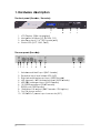
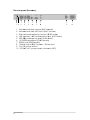
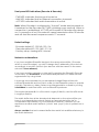
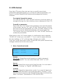
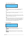
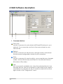
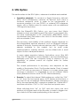
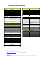
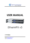
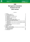
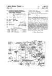
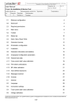
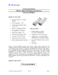
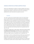
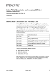
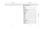
U R MA
USE
MANU
UA
AL
E herrMP
Eth
PX v3
3
We
ebsite: http:://www.sigm
macom.gr
Co
ontact: info@
@sigmacom
m.gr
Sup
pport: supp
port@sigmac
com.gr
OCUMENT REVIEWS
R
DO
Date
01 Mar
M 2014
20 Feb
F
2015
10 Mar
M 2015
2
Version
V
1.0
1.1
1.2
Notes
Initial releasse
Rephrase of
o some sections
Merged witth SFN optio
on User Man
nual
Dea
ar customerr,
Afte
er introducing our DDS-30 FM Exxciter in 201
10, the first in the wo
orld capable to
acc
cept Digital MPX (MPX over AES), it was time to solve an
nother prob
blem: there was
no Digital
D
MPX
X STL in the market! Alsso, the existting Analog
g MPX STLs c
could not meet
m
our high standa
ards in orde
er to exploit the full cap
pabilities of DDS-30.
D
o design a Digital
D
MPX STL,
S which could
c
transp
port Digital MPX,
M
That’s why we decided to
g MPX, anallog L/R, and
d digital L/R
R (over AESS) modes. Since
beside the classic analog
ns of the “e
everything IP”
I concep
pt, we could
dn’t select something else
we are big fan
n IP transmisssion!
than
y
hands, you have the
t
EtherMP
PX IP STL, which
w
is the result of ou
ur research and
In your
dev
velopment. Since versiion 3, an LCD
L
user interface and SFN overr IP capabilities
add
ded, so you don’t need
d GPS receiv
vers any mo
ore!
ways with 24bit professio
onal high-end audio performance
e and minim
mal latency
y, we
Alw
cou
uld comparre the perrformance of EtherMP
PX to a ca
able! Even if EtherMP
PX is
designed to be
e a perfect match with
h our DDS-3
30 FM Excite
er, you can use it to de
eliver
alog MPX to
o any othe
er exciter, and
a
you wiill notice im
mmediately the differe
ence
ana
com
mpared to any
a analog FM STL.
MPX and tha
ank you for selecting us
u for your business!
So, enjoy using your EtherM
macom Broa
adcast
Sigm
Marrch 2014
3
Contents
Page
4
1. Hardware description
a. The front panel
b. The rear panel (Encoder)
c. The rear panel (Decoder)
5
5
5
6
2. Installation instructions
a. Encoder connections
b. Decoder connections
c. Audio level adjustments
d. Rear panel LED indicators
e. Front panel LED indicators
f. Default settings
g. Network considerations
7
7
7
7
7
8
8
8
3. LCD menus
a. Navigate the menus
b. Modify parameters
c. The operational mode menu
d. The audio level menu
e. The network settings menu
f. The system information menu
9
9
9
9
10
10
11
4. NMS Description
a. Command buttons
b. Devices list
c. Device properties
d. Silence Detector configuration
e. Diagnostics
12
12
13
13
14
15
5. SFN Option
a. Operation principals
b. Encoder
c. Decoder
17
17
17
18
6. Implementation examples
a. Multicast with VLANs
b. Unicast
19
19
20
7. Technical specifications
21
1. Hardw
ware de
escription
e front pan
nel (Encod
der / Deco
oder):
The
1
1.
2.
3.
4.
2
3
4
LCD Display
D
[20
0x4 charac
cters]
Naviga
ation butttons [UP, DOWN,
D
OK]
Monito
or output [1/4” TRS Female ja
ack]
Status LEDs [ACT, LINK, PW
WR]
The
e rear pan
nel (Encod
der):
1 2
3
4
5
6
7
8
1. Unbala
anced MP
PX input (BNC fema
ale)
2. Excesssive input level alarrm LEDs (L//R)
3. Right channel
c
b
balanced
input (XLR
R3 female
e)
4. Left ch
hannel / MPX
M balan
nced inpu
ut (XLR3 fe
emale)
5. AES/EB
BU balanc
ced input (XLR3 fem
male)
6. 10/100
0 Ethernett port (RJ4
45 female)
7. RS232 port (DB9
9 female)
8. 10MHzz input & output
o
(BN
NC female
e – SFN op
ption)
9. On/Offf power switch
s
10. 100-24
40VAC po
ower input connector (IEC)
5
9
10
The
e rear pan
nel (Decod
der):
1 2
3
4
5
6
7
8
1. Unbala
anced MP
PX outputt (BNC fem
male)
2. Unbala
anced AU
UX MPX input (BNC female)
3. Right channel
c
b
balanced
output (X
XLR3 male
e)
4. Left ch
hannel / MPX
M balan
nced outp
put (XLR3 male)
5. AES/EB
BU balanc
ced outpu
ut (XLR3 male)
m
6. 10/100
0 Ethernett port (RJ4
45 female)
7. RS232 port (BD9
9 female)
8. 10MHzz output (B
BNC fema
ale – SFN option)
o
9. On/Offf power switch
s
10. 100-24
40 VAC power inpu
ut connec
ctor (IEC)
6
9
10
2. Installa
ation in
nstructions (E
Encode
er & De
ecoderr):
b
Encod
der & Deco
oder in a 19” rack.
1. Install both
2. Conne
ect power and
a
Ethern
net cables as shown below:
Enc
coder con
nnections
[1]
•
•
•
•
[2
2]
[4]
[3]
Connect the MPX ou
utput of you
ur audio pro
ocessor / ste
ereo encoder
Connect the RJ45 LA
AN cable off your local network
Connect the IEC pow
wer cable (100-240VAC
(
C, 50-60Hz)
Turn the power
p
switc
ch on
Dec
coder con
nnectionss
[1] [2]
•
•
•
•
•
[3
3]
[5]
[4]
Connect the MPX ou
utput of the
e EtherMPX Decoder
D
to
o your FM Exxciter
Connect your backu
up audio so
ource to AUX
X IN
Connect the RJ45 LA
AN cable off your local network
Connect the IEC pow
wer cable (100-240VAC
(
C, 50-60Hz)
Turn the power
p
switc
ch on
dio levels adjustment
a
t at Encode
er
Aud
Ana
alog audiio input at
a Encoder should not exc
ceed +6dB
Bu (4.37Vpp).
Sug
ggested no
ominal rang
ge is 0dBu (2.19Vpp) to +4dBu (3.47Vpp)..
The
e audio outputs at th
he Decode
er will prov
vide the sa
ame audio
o level (1:1) as
fed into the Encoder.
E
A
Analog
and digital outputs
o
of Decoder are opera
ating
simultaneously.
ar panel LED indicatio
ons at Enco
oder:
Rea
- OV
VFL LEDs (ttwo, one fo
or each an
nalog inpu
ut): Indicate
es extreme
ely audio le
evel
that needs im
mmediate attention,, otherwise
e damage
e may occ
cur at ana
alog
ut stages of
o the Enco
oder.
inpu
7
Front panel LED indications (Encoder & Decoder):
- PWR LED: Indicates that power is turned on
- LINK LED: Indicates that an Ethernet connection is present.
- ACT LED: Indicates that audio transmission is active.
Note: When Encoder is configured in “Unicast” mode and powered on,
it searches for the Decoder (ACT LED is blinking every second). When a
connection is established, ACT LED at Encoder & Decoder stay always
on. If connection is lost, Encoder will cease transmission after 10 minutes
and will start the search sequence each 17 seconds.
Default settings:
- Encoder default IP: 192.168.1.90 / 24
- Decoder default IP: 192.168.1.91 / 24
- Factory setup: Analog MPX, Unicast
Network considerations:
If you have multiple EtherMPX devices in the same network (like 1 Encoder
and 2 or more Decoders), you MUST change the IP addresses of the devices
accordingly to avoid IP conflicts (two devices with the same IP in the same
network is never allowed).
If you have multiple networks or other traffic reaching the EtherMPX Encoder
or Decoder, you must filter it. A recommended practice is to make network
segmentation by using VLANs.
It is strongly recommended to use transparent bridge Ethernet links with
sufficient bandwidth and low jitter in order for the EtherMPX system to operate
normally. The latency, delay variance and fragmentation caused by routing,
is forbidden for real-time traffic such as EtherMPX produces.
The required bandwidth for L/R mode is roughly 2.5Mbit/s, and for MPX mode
is roughly 4.8Mbit/s.
The audio buffer size at the decoder side depends on the network jitter you
have in your transmission network. Select an appropriate buffer size to
compensate the instability of your transmission network, otherwise you will
experience audible audio artifacts (“clicks” and “pops”) due to packet loss or
drops.
Always consider that an increased buffer size results into additional latency to
the audio delivered.
8
3. LCD menus:
From the LCD menus the user can view or modify some basic
parameters (described below). To control all system parameters, you
have to use the EtherMPX NMS (Network Management System)
software.
To navigate through the menus:
You can use the “UP” and “DOWN” buttons in the front panel, to
navigate through the User Interface menus displayed in the LCD.
To modify a parameter:
Press once the “OK” button and a blinking cursor should appear
in the screen. Use the “UP” and “DOWN” arrow buttons to move
the cursor over the parameter you want to modify. When you set
the cursor over the desired parameter, click once again the
“OK” button. Now you can use the “UP” and “DOWN” buttons to
modify the parameter.
When done, click “OK” button again. A confirmation menu appears
“SAVE? Y/N” where you can select “Y” if you want to apply and save
the new settings, or “N” to discard any changes you made.
If you don’t push any button within 30 seconds, the system discards any
changes and returns to the main menu.
1. Menu: Operational mode
Format :
Source :
IP Mode:
MPX
Analog
Unicast
More>
Format:
Enc & Dec: Select the audio format you need to transport
through EtherMPX. You can select between “MPX” or “L/R”.
Source:
Enc only: Select the source port of the Encoder. You can select
between “Analog” or “Digital” (AES/EBU) input.
IP Mode:
Enc only: Select the transmission mode. If you want to feed only
one EtherMPX Decoder in your network, select “Unicast”. If you
need to feed more than one EtherMPX Decoders simultaneously,
select “Multicast” (Destination IP: 239.255.255.239).
9
2. Menu: Audio level
Input
A
B <Back
dBFS
-10.3
More>
A: Displays the audio level of L/MPX channel
B: Displays the audio level of Right channel (only in L/R mode)
Audio levels are displayed as a bar graph (VU meter) and as
numerical value in dBFS. Please note that this is a display only
menu. You cannot modify any parameter.
3. Menu: Network settings (Encoder)
ID :
SIGMACOM ENCODER
IP :
192.168.001.090
Clk: Int
SFN:Off
<Back
More>
ID:
Displays the device name. You cannot modify this parameter
from the LCD menu, you have to use the EtherMPX NMS
software.
IP:
Displays the device IP address. You can modify this parameter
within the range of 1.0.0.1 to 254.255.255.254.
Clk:
Selects the reference clock source “Int” or “Ext”. You cannot
modify this parameter from NMS to avoid loss of communication.
Only local modification is allowed. When selecting “Int”, the
Encoder uses the internal 10MHz TCXO reference. When
selecting external, uses an external 10MHz reference connected
at the rear “10MHz INPUT” female BNC connector. If the external
10MHz reference is lost, system halts.
SFN:
Displays the operational status of the SFN option (if installed). The
“Off” status disables the Master Clock. When “On” the Master
Clock is enabled.
10
Menu: Network settings (Decoder)
ID :
SIGMACOM DECODER
IP :
192.168.001.091
Att: 0.0
SFN:Off
<Back
More>
ID:
Displays the device name. You cannot modify this parameter
from the LCD menu, you have to use the EtherMPX NMS
software.
IP:
Displays the device IP address. You can modify this parameter
within the range of 1.0.0.1 to 254.255.255.254.
Att:
Displays the analog output attenuation setting. A value of 0dB
means no attenuation. You can modify this parameter in steps of
0.5dB within the range 0.0dB to Mute.
SFN:
Displays the operational status of the SFN option (if installed). The
“Off” status means that the device is running on the internal
clock. When “On” the device is synchronized to the Best Master
clock elected from the network (please refer to IEEE1588v2
protocol specifications for more details on this).
4. System information
DSP =
CPU =
<Back
Sigmacom EtherMPX v3
v3.42
v3.42
DSP:
Enc & Dec: Displays the firmware version running in the main
processor. You cannot modify this parameter.
CPU:
Enc & Dec: Displays the firmware version running in the O&M
(Operation & Maintenance) processor. You cannot modify this
parameter.
11
4. NMS Software description
1
2
3
4
1. Command buttons
Discovery
Use this command to auto detect all EtherMPX devices in your
network. Your computer must be in the same subnet as your
devices are.
Refresh
Use this command to discard any changes made, and reload
the last saved configuration stored in your computer.
Save
Use this command to save locally in your computer any changes
made, and simultaneously send them to the selected device
(Encoder or Decoder).
Play
This command is available only when the selected device is an
Encoder device. Use this command to start audio level capture
and display it in real time at the VU meter located at the down
right corner of the “Diagnostics” area.
12
Stop
This command is available only when the VU meter is running.
Use it to stop audio level capture from Encoder.
2. Devices list
In this area will be displayed all the devices discovered in your
network after you used the “Discovery” command button.
icon: Indicates an Encoder device
icon: Indicates a Decoder device
Next to each icon, the device name and MAC address is displayed.
3. Device properties
When you click on a device in the “Devices list” area, its properties
and parameters are displayed here.
•
•
•
•
•
•
•
•
•
•
•
13
System type: ENCODER or DECODER (non modifiable)
DSP version: The firmware version running in the main processor
of the selected device (non modifiable)
MAC address: The MAC address of the network interface of the
selected device (non modifiable)
Serial number: The production serial number of the selected
device (non modifiable)
System name: View or modify the human friendly name of the
selected device. Highly recommended if you have more than
one Encoder or more than one Decoder in your network. This
helps you to identify the proper device to manage.
System IP: View or modify the IP address of the selected device.
Gateway IP: View or modify the network gateway IP address of
the selected device.
Network mask: View or modify the network mask of the selected
device.
VLAN: Reserved for future releases. User cannot modify this.
SFN option: Only available when SFN option is installed in the
selected device.
Audio routing: This is a Decoder only functionality. View or modify
the audio route of the selected Decoder. Use the drop down
menu to select between the available options:
o Force external: Take the audio from AUX IN and pass it to
the MPX OUT
o Force internal: Take the audio from Ethernet and pass it to
the MPX OUT
o Auto detect: Enables the Silence Detector (see below).
•
•
•
•
•
•
•
•
Audio type: View or modify the audio format of the selected
device. Use the drop down menu to select between “MPX” or
“L/R”.
Audio source: This is an Encoder only functionality. View or
modify the input source of the Encoder. Use the drop down
menu to select between “Analog” or “Digital” (AES/EBU) inputs.
TX type: This is an Encoder only functionality. View or modify the
audio over IP transmission mode at the Encoder. Use the drop
down menu to select between “Unicast” (one Encoder to one
Decoder) or “Multicast” (one Encoder to many Decoders). When
in “Multicast” packets sent from Encoder, will have destination IP
as defined in the “Multicast IP” field box (see below).
Remote / Multicast IP: This field has a double purpose. In Encoder
with TX Type = Unicast, you type the IP address of the target
Decoder to transmit to. In Encoder with TX Type = Multicast you
type the destination Multicast IP address in the range of 239.0.0.1
to 239.255.255.254. The Decoders participating in this group, must
be also configured to “listen” to the same multicast IP address.
Bounded to: Reserved for future releases, has no effect.
Buffer size: This is a Decoder only functionality. View or modify the
audio buffer size of the selected Decoder. Please refer to
“Network considerations” section above.
Threshold: This is a Decoder only functionality and it is enabled
only when “Auto detect” audio routing is selected. This is a
parameter of the integrated Silence Detector in the Decoder,
and defines the audio level threshold to start a countdown timer
before it bridges the AUX IN to the MPX OUT connector
(assuming that the audio over IP is lost).
Timeout: This is a Decoder only functionality and it is enabled only
when “Auto detect” audio routing is selected. This is a parameter
of the integrated Silence Detector in the Decoder, and defines
the initial value of the countdown timer.
Silence Detector example: Threshold = -18dBu, Timeout = 20 sec.
If the audio level coming from the EtherMPX encoder is below
-18dBu for 20 consecutive seconds, the Silence Detector will assume
that the audio over IP is lost, and will bridge the AUX IN to the MPX
OUT connector.
When the audio level is restored above -18dBu for 5 consecutive
seconds, the Silence Detector assumes that the audio over IP is OK
and disconnects the AUX IN from the MPX OUT connector.
If your program has long periods of silence or long pauses between
songs and talent, it is recommended to set the audio routing of the
Decoder to “Force internal”.
14
Note: The 5 seconds restoration timer is factory fixed and cannot be
modified by the user.
4. Diagnostics
When you have selected a device in the “Devices list” area, you
can use the following tools:
•
•
Ping response: Click with your mouse this button, to perform
an ICMP ping towards to the IP address of the selected
device. The ping is originating from your computer IP address,
so it must be in the same subnet as the device is.
If there is a ping response, the button turns in green color and
the response time is displayed.
If there is no response within a second, the button turns into
red color with a “Failure” caption.
Statistics: Every EtherMPX device keeps statistical counters
about Ethernet packets being transmitted or received. If the
SFN option is installed, statistical counters about the
synchronization performance are displayed. Click on the
“Get" button, and a new window will appear (see below):
-
15
Good TX Frames: Ethernet frames transmitted OK from the device (no
internal underruns / overruns, network collisions).
Bad TX Frames: Ethernet frames that failed to be transmitted from the
device (possible causes: internal underrun /overrun, or network
collisions).
Good RX Frames: Ethernet frames received OK from the device (no
CRC errors, no underruns / overruns, no network collisions).
Bad RX Frames: Ethernet frames received, but dropped by the device
(possible causes: CRC errors, internal underrun / overrun, network
collisions).
Good PTP Sync: (Only available if SFN option is installed and enabled).
Number of PTP SYNC messages received OK and took into account by
-
-
-
•
16
the device algorithms to calculate and calibrate on-the-fly the sync
parameters.
Bad PTP Sync: (Only available if SFN option is installed and enabled).
Number of PTP SYNC messages received, but rejected by the device
algorithms. Possible causes: Glitching Master Clock, heavy loaded
network, many irrelevant Ethernet packets that must be filtered out.
Clock difference: (Only available if SFN option is installed and
enabled). The measured mismatch between the Master Clock and the
local clock, expressed in nanoseconds (nS). This value must be as low
as possible to indicate that there is a good sync with the Master Clock.
Cases of >100nS difference, indicate a network problem. Possible
causes: excessive latency fluctuations caused by Ethernet switches or
wireless transmission.
Measured delay: (Only available if SFN option is installed and
enabled). The delay between local device and Master Clock device.
Reset Button: Click this button to reset counters to zero. A confirmation
dialog appears to verify this operation.
Refresh Button: Click this button to update the counters (fetch from
device).
Audio level: This is an Encoder only functionality. This is a real
time VU meter, which displays the audio level of the selected
Encoder. To start monitoring the audio level, select the
Encoder device you want, and click the “Play” button on the
top strip. To stop the audio monitoring, just click the “Stop”
button next, or select some other device from the “Devices
list”. Keep in mind that audio monitoring causes a reverse
direction IP traffic of about 100-200kbit/s.
5. SFN Option
This section refers to the SFN Option, wherever is installed and enabled.
•
Operation principals: To construct a Single Frequency Network
(SFN), a.k.a. isofrequency network, all devices must have a
common reference clock in order to be synchronized. A
common practice is to use GPSDO, or external GPS reference
clocks, with a 10MHz output (in some cases, with an additional
1PPS signal output also).
With the EtherMPX SFN Option, you can have that 10MHz
reference clock, provided by each Decoder. To accomplish this,
we have implemented a PTP mechanism (IEEE1588v2) which
synchronizes each Decoder to the clock of the Encoder, which
acts as a Master Clock.
The accuracy and stability of this method, heavily depends on
the intermediate network elements, such as Ethernet switches,
wireless IP links etc. Special network devices with PTP support are
already available in the market, but for small scale
implementations, ordinary devices can be utilized with a small
impact to the overall performance.
In cases where excessive latency fluctuations occur (like WiFi
links), the PTP algorithms cannot handle it, and synchronization is
extremely poor. We are constantly trying to improve our PTP
algorithms, so please consult our support team for further
information.
The overall performance & accuracy, also depends on the
quality of the Master Clock. The Encoder Master Clock is based
on a TCXO with an accuracy of 2.5ppm, so in cases where more
accuracy is required, it is suggested to use an external 10MHz
clock (Rubidium atomic clock, or GPS 10MHz reference).
•
Encoder: To select the internal 10MHz reference, switch the “CLK”
to “Int” from the front panel menu (LCD display and buttons). If
you want to use an external 10MHz reference, please connect it
first to the rear female BNC connector marked as “10MHz INPUT”
and then switch the “CLK” to “Ext” from the front panel menu.
When switching from “Int” to “Ext” and vice versa, user must
perform a full power reset of the Encoder, in order to trigger a resync state to all Decoders participating in the network.
17
The rear female BNC connector marked as “10MHz output”
provides 10MHz 3.3Vpp CMOS signal (AC coupled) to drive any
other device needed.
In case you are using an external 10MHz reference and it is lost,
the system switches into a st-by mode (no audio or SYNC packets
are transmitted). As a protection measure, you cannot modify
“Int” / “Ext clock selection from the NMS software – only local
modifications are allowed.
To turn on the PTP operation, switch the “SFN” selection to “On”
(this can be modified from the front panel menu or the NMS, see
previous sections). When enabled, the PTP mechanism is sending
every 2 seconds a UDP port 319 SYNC message with a
destination multicast IP of 224.0.1.129. The time stamping engine
is capable of 8nS discrimination.
•
Decoder: To turn on the PTP operation, switch the “SFN” selection
to “On” (this can be modified from the front panel menu or the
NMS - see previous sections).
When enabled, the device captures SYNC messages and the
PTP algorithms process them on-the-fly and apply corrections to
the local clock. After a short (15-30 minutes) to a medium (30-60
minutes) period of time, the averaging errors should be
minimized and the 10MHz output of the Decoder will be in close
sync to the Master Clock (Encoder).
The accuracy and stability of the synchronization, heavily
depends on the intermediate network elements, such as
Ethernet switches, wireless IP links etc. The environment
temperature can also affect the accuracy and stability of
synchronization.
If after 1 hour of operation, the “Clock Difference” counter (see
“Statistics” section above) is over 100nS, then you need to
investigate what causes this instability in your network.
Also, an excess of 10:1 ratio between “Good PTP Sync” and “Bad
PTP Sync”, also indicates a network issue that disturbs the
operation of the PTP mechanism.
In cases where excessive latency fluctuations occur (like WiFi links), the
PTP algorithms cannot handle it, and synchronization is extremely poor.
We are constantly trying to improve our PTP algorithms, so please
consult our support team for further information.
18
6. Implem
menta
ation ex
xample
es
Exa
ample 1:
Two
o different radio pro
ograms must
m
be tra
ansported
d to two different TX
X
site
es over sing
gle IP radio links. We
W need both
b
progrrams at ea
ach TX site
e.
Bec
cause two
o Encoderrs are ope
erating in “Multicast” mode ((this is
nee
eded in order to feed more than
t
one Decoderr), these tw
wo stream
ms
mu
ust be logically sepa
arated insside the ne
etwork.
a
t
this,
you need Etherrnet switches that support
s
VLLANs.
To achieve
u will need
d to define separatte VLANs - one for each
e
radiio program
m
You
(VLLAN 10 forr radio pro
ogram 1, and
a
VLAN
N 20 for rad
dio progra
am 2 in ou
ur
exa
ample). Ev
ven if you have isolated netw
work segm
ments, you
u should
deffine uniqu
ue IP addrresses to each
e
deviice.
Notte that the
e ports co
onnected to IP radiio links, mu
ust be configured as
a
trun
nk ports to
o allow all VLANs to
o pass thro
ough. The ports con
nnected to
Enc
coders & Decoders
D
s, must ad
dd the app
propriate VLAN tag
gs to ingre
ess
trafffic, and discard
d
VLLAN tags on
o egress traffic.
19
ample 2:
Exa
Two
o different radio pro
ograms must
m
be tra
ansported
d to two different TX
X
site
es over sing
gle IP radio links. We
W need only
o
one program
p
a
at each TX
X
site
e.
To achieve
a
t
this,
you can use orrdinary pla
ain Ethernet switche
es.
Bec
cause two
o Encoderrs are ope
erating in “Unicast” mode (e
each one is
paiired to on
nly one De
ecoder), th
hey can co-exist
c
in the same
e network
k
with
hout the need
n
of VLANs.
V
Of course ea
ach devic
ce must also have a
unique IP ad
ddress.
Notte:
ese are on
nly two me
ere examples. The flexibility
f
a
and
the possibilitiess of
The
usin
ng EtherM
MPX over an
a IP netw
work are endless.
If yo
ou need any
a assista
ance on designing
d
your own
n transmisssion network,
ple
ease do no
ot hesitate
e to consu
ult us!
20
7. Technical specifications
GENERAL
DECODER
Model name
EtherMPX v3
Output name
Port A
Dimensions
19” 1U chassis
Output type
Digital electrical interface
230VAC 50Hz, 12W
Connector
XLR-3 male
Operating temp
-20 to +60 Celsius
Impedance
110 Ohm balanced, transformer isolated
Transport protocol
Proprietary UDP Unicast or Multicast
Format
AES3
IETF RFC2474 compliant
Maximum data rate
12.288 Mbit/s
Audio sample rate
48kHz for L/R output, 192kHz for D-MPX
Audio sample resolution
24 bit
Output name
Port B
Output type
Analog electrical interface - 2 outputs
Connector
2 x XLR-3 male (balanced R, L/MPX)
1 x BNC (female unbalanced MPX only)
Power supply
QoS management
Audio compression
None (Linear PCM)
Audio resolution
8 – 24bit for Digital L/R & MPX input
24bit for Digital L/R & MPX output
24bit for Analog L/R & MPX output
Audio sample rate
8 – 192kHz input for Digital L/R input
174-192kHz input for Digital MPX input
48kHz internal for Analog L/R input
192kHz internal for Analog MPX input
L/R mode: 5mS (up to 40mS on busy net)
MPX mode: 2,5mS (up to 20mS on busy)
Impedance
1 kOhm
Audio latency
DAC resolution
24 bit
DAC sample rate
48kHz for L/R output, 192kHz for A-MPX
Network usage
L/R mode: 2,37 Mbit/s typ
MPX mode: 4,74 Mbit/s typ
Audio monitor
Stereo ¼” Female jack in front panel
DAC THD+N
-108dB (0.0004%) at 48kHz L/R out
-96dB (0.0015%) at 192kHz A-MPX out
DAC SNR
129dB at 48 or 192kHz
DAC Dynamic range
129 dB (A weighted) at 48 or 192kHz
ENCODER
Input name
Port A
Channel separation
124 dB at 48kHz L/R output
Infinite at 192kHz A-MPX output
Input type
Digital electrical interface
Reference output
3.47Vpp (+4dBu) for 0 dBFS
Connector
XLR-3 female
Out BW @ 48kHz SR
-0.1dB @ 21.8 kHz
Impedance
110 Ohm balanced - transformer isolated
Out BW @ 192kHz SR
-0.1dB @ 87.2 kHz
Supported formats
AES3, IEC60958, S/PDIF
Maximum data rate
12.288 Mbit/s
Audio sample rate
32 - 192 kHz (174-192kHz for D-MPX)
Audio sample
resolution
24 bit
SFN Operation
Ouputs
1x10MHz
Connector
BNC Female
Impedance
50 Ohms
Input name
Port B
Delay compensation
Auto up to 20mS (basic version)
Input type
Analog electrical interface - 2 inputs
Synchronization
PTP (IEEE-1588), <8nS accuracy
Connector
2 x XLR-3 female (balanced R, L/MPX)
1 x BNC female (unbalanced MPX only)
Impedance
1 kOhm
ADC resolution
24 bit
ADC sample rate
48kHz for L/R input, 192kHz for A-MPX
ADC THD+N
-106dB (0.0005%)
ADC Dynamic range
121 dB (no weighting)
Channel separation
135 dB
Reference input
3.47Vpp (+4dBu) for 0 dBFS
Input BW @ 48kHz
SR
-0.1dB @ 20 kHz
Input BW @ 192kHz
SR
-0.1dB @ 80 kHz
NOTE: Technical specifications are subject to change without notice. Please contact
us if you have questions, or to get latest information and updates.
Sigmacom Broadcast support:
[email protected] - or call +302312209905.
21