1
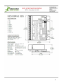
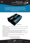
G251 STEP MOTOR DRIVE
REV 9: November 16, 2009
Thank you for purchasing the G251 drive. The G251 microstep drive is warranted to be free of manufacturing defects for 1 year
from the date of purchase. Anyone who is dissatisfied with it or is unable to make it work will be cheerfully refunded the purchase
price if the G251 is returned within 15 days of the purchase date and is in like-new condition.
PLEASE READ FIRST BEFORE USING THE G251
Before beginning, be sure to have a suitable step motor, a DC power supply suitable for the motor and a current set resistor. The
motor’s rated phase current must be between 0 amps and 3.5 amps and the current set resistor may be a 1/4 watt, 5% part.
Finally have a STEP and DIRECTION pulse source available.
G251 TERMINAL WIRING
The G251 uses a 12 position 3.5mm terminal block. The wire gauge must be between 16 and 26 (AWG) and the wire must be
stranded. Do not solder tin the wire strands as this will cause it to fatigue over time and it will eventually break. Do not exceed 30
in-oz (0.2 Nm) torque on the terminal screws.
TERMINAL 1
Power Ground
Connect the negative (black) lead of your power supply to this terminal.
TERMINAL 2
Power (+)
Connect the positive (red) lead of your power supply to this terminal. It must be between +15VDC to
+50VDC.
TERMINAL 3
Current Set
Connect one end of your current set resistor to this terminal.
TERMINAL 4
Current Set
Connect the other end of your current set resistor to this terminal.
TERMINAL 5
Motor Phase A
Connect one end of your “Phase A” motor winding here.
TERMINAL 6
Motor Phase /A
Connect the other end of your “Phase A” motor winding here.
TERMINAL 7
Motor Phase B
Connect one end of your “Phase B” motor winding here.
TERMINAL 8
Motor Phase /B
Connect the other end of your “Phase B” motor winding here.
TERMINAL 9
Direction
Connect the DIRECTION signal to this terminal.
TERMINAL 10
Step
Connect the STEP signal to this terminal.
TERMINAL 11
Disable
This terminal will force the winding currents to zero when shorted to ground (TERMINAL 12).
TERMINAL 12
Common
Connect this to your logic (controller) ground.
POWER SUPPLY CONNECTION
TERMINAL 1
Power Ground
Connect the power supply ground to this terminal
TERMINAL 2
Power (+)
Connect the power supply “+” to this terminal
1
G251 STEP MOTOR DRIVE
REV 9: November 16, 2009
The power supply voltage must be between 15VDC and 50VDC. The maximum power supply current required is 67% of the
motor’s rated phase current. An unregulated power supply may be used as long as the voltage stays between the limits; keep the
ripple voltage to 10% or less for best results.
CAUTION! Power supply voltage in excess of 50VDC will damage the G251.
CAUTION! Never put a switch on the DC side of the power supply! This will damage, if not destroy, your drive!
A very accurate calculation of power supply voltage is to find your motor’s inductance, and put it into the following equation.
32 * (√mH inductance) = Power Supply Voltage
If your motor has 2mH of inductance, the equation would look as follows.
32 * (√2) = 45.12V
In the example above 45.12V is the maximum voltage for that specific motor; any voltage above this will create unnecessary
heating and any voltage below that will get you proportionally less speed than you could otherwise get at 45.12V.
CURRENT SET RESISTOR
TERMINAL 3
Current Set
Connect the current set resistor to this terminal.
TERMINAL 4
Current Set
Connect the other end of the current set resistor to this terminal.
This input programs the G251’s current output to the motor windings. The current set resistor is a linear calculation of 1K ohms of
resistance for every amp of motor winding current. This means that a 2.3A per phase motor will require a 2.3K ohm resistor on
terminals 3 and 4. If your motor is 3.5A or above you can leave these terminals open and the drive will self limit to 3.5A; however,
you will lose the auto current reduction feature of the drive. If you require this feature then a 3.5K resistor should be put on the
drive.
MOTOR CONNECTION
TERMINAL 5
Phase A
Connect one motor winding to this terminal
TERMINAL 6
Phase /A
Connect the other end of the winding to this terminal
TERMINAL 7
Phase B
Connect the other motor winding to this terminal
TERMINAL 8
Phase /B
Connect the other end of the winding to this terminal
Connect one motor winding to terminals 5 and 6. Connect the other winding to terminals 7 and 8. Turn the power supply off when
connecting or disconnecting the motor. If the motor turns in the wrong direction, reverse the motor winding connections to
terminals 5 and 6.
CAUTION! Do not short the motor leads to each other or to ground; damage will result to the G251.
4-wire, 6-wire and 8-wire motors may be used. When 6-wire motors are used, they may be connected in half winding or full
winding. This is equivalent to an 8-wire motor connected in parallel or series. If a motor is connected in series or full winding, the
motor’s phase current rating is half of its parallel or unipolar rating. The choice depends on the high-speed performance required;
a parallel-connected motor will provide twice the power of a series-connected motor at the same power supply voltage.
STEP AND DIRECTION INPUTS
TERMINAL 9
Direction
Connect the DIRECTION line to this terminal.
2
G251 STEP MOTOR DRIVE
REV 9: November 16, 2009
TERMINAL 10
Step
Connect the STEP line to this terminal.
These terminals can be driven with 3.3V or 5V logic. If 3.3V logic is used then the input current is -1mA for logic “0” and zero for
logic “1”. If 5V logic is used then the input current is -1mA for “0” logic and 0.67mA for logic “1”.
DISABLE PIN
TERMINAL 11
Disable
This terminal will force the winding currents to zero when shorted to ground (TERMINAL 12).
Shorting this input to ground (terminals 11 to 12) forces winding currents to zero and stops all output switching activity. The G251
will continue totalizing step and direction inputs if any are sent. The power supply current drops to less than 15mA. The motor will
return to its original position when the disable input is released if no step pulses have been sent and the motor has not been
moved more than 2 full steps.
COMMON PIN
TERMINAL 12
Common
Connect this terminal to the controller signal ground
HEATSINKING
The G251 needs heatsinking for current settings greater than 3 amps. The case temperature (measured on the bottom plate)
should not exceed 70 degrees C, and for best life should be kept to 50 degrees C or less. Use heatsink compound between the
G251 and the heatsink.
CAUTION! Current settings above 3 Amps without a heatsink will result in damage to the G251.
The drive must be heatsinked to a piece of aluminum, preferably with fins and a fan to increase heat dissipation and surface area.
Do not screw the drive directly to the door of your control cabinet, as this will typically not provide adequate heatsinking
properties.
ADJUSTING THE TRIMPOT
This trimpot adjusts the motor for the smoothest possible low-speed operation. Set the motor speed to about 1/4 revolution per
second, and then turn the trimpot until a distinct null is noted in the motor’s vibration. This will result in the most even microstep
placement for a given motor and power supply voltage.
DISCLAIMER
CERTAIN APPLICATIONS USING POWER PRODUCTS MAY INVOLVE POTENTIAL RISKS OF DEATH, PERSONAL INJURY
OR SEVERE DAMAGE TO PROPERTY. GECKODRIVE INC. PRODUCTS ARE NOT DESIGNED, AUTHORIZED OR
WARRANTED TO BE SUITABLE FOR USE IN LIFE-SUPPORT DEVICES OR OTHER CRITICAL APPLICATIONS. INCLUSION
OF GECKODRIVE INC. PRODUCTS IN SUCH APPLICATIONS IS UNDERSTOOD TO BE FULLY AT THE PURCHASER’S
OWN RISK.
In order to minimize risks associated with the purchaser’s application, adequate design and operating safeguards must be
provided by the purchaser to minimize inherent or procedural hazards. GECKODRIVE INC. assumes no liability for applications
assistance or the purchaser’s product design. GECKODRIVE INC. does not warrant or represent that any license, either express
or implied, is granted under any patent right, copyright or other intellectual property right of GECKODRIVE INC.
3
G251 STEP MOTOR DRIVE
REV 9: November 16, 2009
4