1
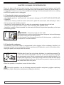
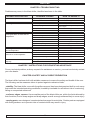
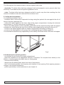
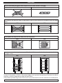
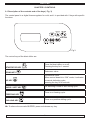
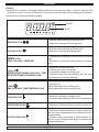
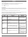
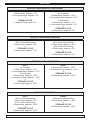
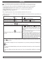
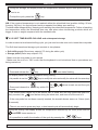
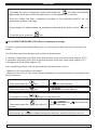
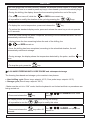
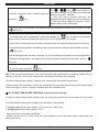
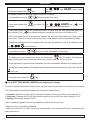
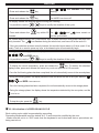
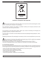
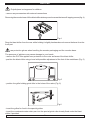
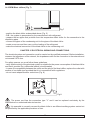
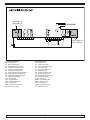
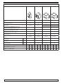
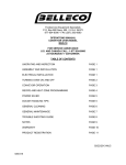
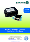
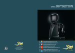
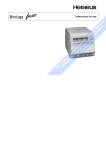
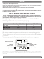
ENGLISH
Thank you for choosing this product.
Please read the warnings contained in this manual carefully, as they provide important information
regarding safe operation and maintenance.
Make sure to keep this manual for any future reference by the various operators.
In some parts of the manual, the
be observed for safety purposes.
symbol appears, indicating an important warning that must
CHAPTER 1 BOUNDARY CHARACTERISTICS OF OPERATION
The blast chiller has been designed and built to operate in optimal conditions at temperatures of
up to +43°C, with adequate air circulation. In places with characteristics that are different from the
requirements, the stated performance cannot be guaranteed.
The supply voltage must be 230V +/- 10% 50Hz as standard, or as indicated on the EC label.
The following table shows the cooling and/or freezing capacity in kg.
Model
Blast chilling +90°C / +3°C
BASIC MINI
BASIC ABF 03
BASIC ABF 05 E
BASIC ABF 05 C
Rapid freezing +90°C / -18°C
7 Kg.
10 Kg.
14 Kg.
20 Kg.
4 Kg.
5 Kg.
9 Kg.
12 Kg.
N.B.: the times and quantities in kg above are valid for products with a maximum thickness of 4 cm.
The blast chiller complies with the European directives as described in detail in the Annex “EC Declaration
of Conformity”
The data are reported on the EC label placed in the blast chiller, inside the engine compartment.
Manufacturing Company
Modello
Model
Code article
Operating voltage
Power consumption
Type of coolant
Cod.Art
Code
Model
Matricola
Ser. Number
Tensione
Tension
Assorbimento
Absorption
Registration Number
Climate class
CL.
A
Gas
Gaz
Kw
Electrical power
Kg
Quantity of coolant
The manufacturer declines any liability for improper use of the blast chiller, as well as use that could not
have been reasonably foreseen, and for all operations performed on it that disregard the instructions in
the manual.
29
ENGLISH
The main general safety standards are listed below:
- do not use or place electrical devices inside the refrigerated compartments if they are not of the
type recommended by the manufacturer
- do not touch the blast chiller with damp or wet hands or feet
- do not use the blast chiller barefoot
- do not insert screwdrivers or other objects between the guards or moving parts
- do not pull the power cord to unplug the blast chiller from the electricity network
- the blast chiller is not intended to be used by persons (including children) with physical or mental
problems, or lack of experience and knowledge, unless they are controlled or instructed in using the
unit by a person responsible for their safety. Children must be supervised to ensure that they do not
play with the appliance.
- before carrying out any cleaning or maintenance, disconnect the blast chiller from the mains power
supply by turning off the main switch and pulling the plug
- in the event of failure and/or malfunction of the blast chiller, turn it off and to refrain from any attempt
to repair or intervene directly. It is necessary to exclusively contact a qualified technician.
The blast chiller is composed of a modular monocoque coated with different materials and insulated
with polyurethane foam of density 42 kg/m3.
In the design and construction, all measures have been adopted to ensure a blast chiller that complies
with safety and hygiene requirements, such as: rounded interior corners, deep drawing with drain on
the outside for the condensate liquids, no rough surfaces, fixed guards on moving or dangerous parts.
The products must be stored in observance of the load limits given in the table, in order to ensure
an efficient circulation of air inside the blast chiller.
Load capacity
BASIC MINI
BASIC ABF 03
BASIC ABF 05 E
BASIC ABF 05 C
3 x GN 2/3
3 x GN 1/1
5 x GN 1/1
5 x GN 1/1
-
-
5 x EN 60x40
5 x EN 60x40
-
-
6x
6x
The installation must be performed exclusively by a qualified technician
1.1 It is prohibited to remove the guards and safety devices
t is absolutely forbidden to remove safety guards.
The manufacturer disclaims any liability for accidents due to failure to comply with this obligation.
1.2 Information on emergency operations in the event of fire
- disconnect the blast chiller from the electrical outlet or cut off the main power supply
- do not use water jets
- use dry chemical or CO2 extinguishers
30
ENGLISH
CHAPTER 2 CLEANING THE REFRIGERATOR
Since the blast chiller will be used to store food, cleaning is necessary for hygiene and health
protection purposes. The cleaning of the blast chiller has already been carried out at the factory. It
is suggested, however, to carry out an additional cleaning of the internal parts before use, making
sure that the power cord is unplugged.
2.1 Cleaning the interior and exterior cabinet
For this purpose the following are indicated
- the cleaning products: water and mild, non-abrasive detergents. DO NOT USE SOLVENTS AND
THINNERS
- methods for cleaning: wash the interior and exterior parts with warm water and mild soap or with a
cloth or sponge with suitable products
- disinfection: avoid substances that can alter the organoleptic characteristics of the food
- rinsing: cloth or sponge soaked in warm water. DO NOT USE WATER JETS
- frequency: weekly is recommended, the user can set different frequencies depending on the type
of food being stored.
REMARK : Clean frequently the door seals.
Some preserved products could release some enzymes that could damage
the seals causing its quick deterioration.
For the cleaning, use only specific products for this purposes, available also
on request on our sales network.
2.2 Cleaning the condenser
The efficiency of the blast chiller is compromised by the clogging of the condenser, therefore it is
necessary to clean it on a monthly basis. Before carrying out this operation, switch off the blast chiller,
unplug the power cord and proceed as follows:
Fig.1
ALCOOL
With the aid of a jet of air or dry brush, eliminate, in a vertical movement (Fig.
1), the dust and lint deposited on the fins. In the case of greasy deposits,
we recommend using a brush moistened with special cleaning agents. For
models with hinged front, loosen the locking screw and rotate the front panel
on the hinges located at the top. At this point, proceed to clean as done with
the models with fixed front panel.
When the operation is completed, restart the blast chiller.
During this operation, use the following personal protective equipment: goggles, respiratory
protection mask, chemically resistant gloves (gasoline-alcohol).
31
ENGLISH
CHAPTER 3 PERIODIC CHECKS TO BE CARRIED OUT
The following are the points or units of the blast chiller that require periodic checks:
- integrity and efficiency of door seals
- integrity of the grilles in contact with food
- integrity of the fixing hinges of the doors
- integrity of the power cord
3.1 PRECAUTIONS IN CASE OF LONG PERIODS OF INACTIVITY
A long period of inactivity is defined as a stoppage of more than 15 days.
It is necessary to proceed as follows:
- switch off the blast chiller and disconnect it from the power supply
- carry out a thorough cleaning of the interior cabinet, shelves, trays, guides and supports, paying
special attention to critical points such as the joints and magnetic gaskets, as indicated in Chapter 2.
- leave the door partly open to prevent air stagnation and residual humidity
CHAPTER 4 PREVENTIVE MAINTENANCE
4.1 Restarting after a long period of inactivity
Restarting after long inactivity is an event that requires preventive maintenance.
It is necessary to perform a thorough cleaning as described in chapter 2.
4.2 Control of the warning and control devices
We recommend that you contact your dealer for a service or maintenance contract that includes:
- cleaning of the condenser
- verification of the coolant load
- verification of the full cycle operation
- electrical safety
CHAPTER 5 EXTRAORDINARY MAINTENANCE AND REPAIR
All maintenance activities that have not been described in previous chapters are considered
“Extraordinary Maintenance.” Extraordinary maintenance and repair are tasks reserved exclusively
to the specialist personnel authorized by the manufacturer.
No liability is accepted for actions carried out by the user, by unauthorized personnel, or with the use
of non-original replacement parts.
32
ENGLISH
CHAPTER 6 TROUBLESHOOTING
Problems may occur, in the blast chiller, identified as shown in the table:
TROUBLE DESCRIPTION
the blast chiller does not turn on
the refrigeration unit does not start
the refrigeration unit runs continuously but does not reach the set
temperature
the refrigeration unit does not stop at
the set temperature
block of ice on the evaporator
accumulation of water or ice in the
drip tray
POSSIBLE CAUSES
HOW TO REPAIR IT
no power supply
check the plug, socket, fuses, line
other
contact technical support
the set temperature has been reached
set new temperature
defrosting in progress
wait until the end of cycle / turn power off
and on again
control panel failed
contact technical support
other
contact technical support
location is too hot
aerate more
condenser is dirty
clean the condenser
insufficient coolant
contact technical support
stop the condenser fan
contact technical support
insufficient sealing of doors
check the seals / provision of goods
evaporator completely frosted
manual defrosting
other
contact technical support
command panel failed
contact technical support
P1 temperature sensor failed
contact technical support
misuse
see chapter 1.
defrost heater fault
contact technical support
defrost probe P2 damaged
contact technical support
drain clogged
clean the pipette and the drain
blast chiller is not level
check levelling
CHAPTER 7 INSTRUCTIONS FOR REQUESTING ASSISTANCE
For any technical problem, and any requests for assistance or service, you must exclusively contact
your own dealer.
CHAPTER 8 SAFETY AND ACCIDENT PREVENTION
The blast chiller has been built with suitable measures to ensure the safety and health of the user.
The following are the measures taken to protect against mechanical risks:
- stability: The blast chiller, even with the grilles removed, has been designed and built in such a way
that under the intended operating conditions, its stability is suitable for use without risk of overturning,
falling or unexpected movement
- surfaces, edges, corners: the accessible parts of the blast chiller are, within the limits allowed by
their functions, free of sharp angles and sharp edges, as well as rough surfaces likely to cause injury
- moving parts: were designed, constructed and arranged to avoid risks. Certain parts are equipped
with fixed guards so as to prevent risks of contact which may result in injury
33
ENGLISH
The following are the measures taken to protect against other risks:
- electricity: The blast chiller has been designed, built and equipped so as to prevent risks from
electricity, in accordance with the specific legislation in force
- noise: The blast chiller has been designed and built in such a way that risks resulting from the
emission of airborne noise are reduced to the minimum level
8.1 safety devices adopted
It is absolutely forbidden (Fig. 2) :
- to tamper with or remove the evaporator housing casing that protects the user against the risk of
being cut by the evaporator fins
- remove the labels applied at the inner edge of the engine compartment, showing the technical
specifications (1) and the instructions for grounding (2)
- remove the label applied on the evaporator guard and near the electrical wiring inside the engine
compartment, which warns the user to turn off the power supply before working on the unit (3)
- to remove the labels applied inside the engine compartment, indicating grounding (4)
- to remove the label applied on the power cord, indicating the type of power supply (5)
The manufacturer declines any responsibility for the safety of the blast chiller if this were to happen.
Fig.2
8.2 Indications for optimal operation
- do not block the air vents of the engine compartment
- place the foodstuffs on the appropriate shelves or containers. Do not place them directly on the
bottom, or leaning against the walls, doors or fixed guards
- close the doors carefully
- always keep the defrost water drain hole clear of obstructions
- limit, to the extent possible, the frequency and duration of door opening. Each opening causes a
change in the internal temperature
- perform periodically current maintenance (see chapter 3)
34
ENGLISH
AVOID overloading the blast chiller beyond the set limits shown in the table
NO
OK
Do not place the trays too close to each other so as to avoid uneven air circulation inside the blast
chiller
NO
OK
Do not place the trays too far away from the evaporator
NO
OK
Do not concentrate the trays in one area of the blast chiller in case the load is not complete; distribute
its height evenly
NO
OK
In case of interruption or failure of the power supply circuit, prevent the opening of the doors in order to
maintain a uniform temperature inside the blast chiller.
If the problem persists longer than a few hours it is recommended to move the material to a suitable place.
35
ENGLISH
CHAPTER 9 CONTROLS
9.1 Description of the controls and of the keys ( Fig. 3)
The control panel is a digital thermoregulator for cold, and it is provided with 6 keys with specific
functions:
DEFROST
Fig.3
The control keys of the blast chiller are:
START/STOP KEY
DOWN KEY
UP KEY
HARD / SOFT KEY
FREEZING KEY
CHILLING KEY
Turns the blast chiller on or off,
Pressing the key for 1 second.
Reduces a value.
Increases a value.
When control board is in “ON” mode, it activates
a manual defrosting cycle,
pressing the key for 4 seconds.
For selecting a Hard or Soft chilling cycle.
Turns on a freezing cycle.
Turns on a positive chilling cycle.
Nb. To silence the acoustic BUZZER, press and release any key.
36
ENGLISH
Display
Visualization is carried out through a display where you can see four digits – once on, they turn blue
– and twelve icons. For ease of reference, from now on the four digits will be designed as “display”,
and each icon will be identified singularly.
ICONS
DIGIT
FREEZING ICON
CHILLING ICON
HARD ICON
HARD CHILLING / FREEZING
Flashes while selecting a freezing cycle
► Remains on during the freezing cycle
►
►
►
Flashes while selecting a chilling cycle
Remains on during the chilling cycle
Flashes while selecting a Hard chilling or freezing
cycle
► Remains on during the Hard chilling or freezing
cycle
►
Remains on while selecting:
A
chilling cycle with core probe
ICONS
TEMPERATURE-BASED CHILLING / TEM- - A temperature-based freezing cycle
► Flashes during the test attesting that the core
PERATURE-BASED FREEZING ICON
probe has been correctly inserted
►
ICONS
TIME CHILLING / TIME FREEZING ICON
Remains on:
- While selecting a time chilling cycle
- While selecting a time freezing cycle
►
STORAGE ICON
►
►
Remains on during a storage cycle
Flashes when displaying the room’s temperature
DEFROSTING ICON
►
Remains on while defrosting is being carried out
Remains on while precooling is being carried out,
and the room’s temperature has reached the preset parameters
► Flashes when precooling is being carried out,
and the room’s temperature has not reached the
pre-set parameters
►
PRECOOLING ICON
37
ENGLISH
FAHRENHEIT
°F ICON
CELSIUS
°C ICON
MINUTES
min ICON
ON / STAND BY ICON
Remains on when displaying a temperature measured in Fahrenheit degrees
►
Remains on when displaying a temperature measured in Celsius degrees
►
Remains on when displaying a time lapse expressed in minutes (e.g. the duration of a chilling /
freezing cycle)
►
►
Remains on when the unit is in “STAND BY” mode
9.2 INSTRUCTION FOR USE
9.2.1 Start-up
Before starting up the blast chiller, please make sure that the power wiring and the connection have
been performed as per dispositions in chapter 15.
When the control board is fed, a two-seconds lamp test is carried out.
There are 4 statuses of functioning:
OFF status:
►
the unit is not being fed, the display is off
Stand-by status:
►
the unit is being fed and is off
The display only shows the
in red.
icon, coloured
ON status:
the unit is being fed, is on and waiting for a The display shows the room’s temperature
working cycle to be carried out.
►
RUN status:
the unit is being fed, is on, and a working The display shows the following information:
cycle is being carried out.
► if a chilling or freezing cycle with core probe
is being carried out, the display shows the
temperature detected by the probe
► if a chilling cycle or a time-based freezing is being
carried out, the display shows the time remaining
before the end of the current cycle
► if a storage cycle is being carried out, the display
shows the room’s temperature
►
38
ENGLISH
9.2.2 Turn on/off
- Make sure the keyboard is not locked and that no procedures are being carried out.
Press the START/STOP key for 1 second to turn on and off the unit.
The icon
turns on or off.
9.2.3 Operation
The blast chiller carries out chilling or freezing cycles, which can be Hard and Soft, time-based (setting the duration of the cycle) and temperature-based (checking the core temperature of the product
via core probe).
Before each working cycle, a precooling may be carried out (Par. 9.2.10).
Before each cycle with a core probe, a test is carried out, to make sure the probe has been correctly
inserted; if it is not inserted, time-based cycles will start in a time-based mode.
Each chilling / freezing cycle is followed by a storage cycle.
CHILLING
TYPE
CHILLING
SOFT
TEMPERATURE
RANGE
Core temperature of the product +90°C /
+3°C
►
The air temperature inside the room never
goes below zero.
SUGGESTED
PRODUCTS
Delicate, thin or small products such as vegetables,
rice and fried products.
►
CHILLING
HARD
FREEZING
SOFT
Core temperature of the product +90°C /
+3°C
► The air temperature inside the room reaches -20°C.
Ideal for dense, fat, big in
size or packed products.
Core temperature of the product +90°C /
-18°C
Ideal for any foodstuff that,
once freezed, is due to be
stored for many weeks or
months.
Soft freezing is suitable for
delicate and small products,
needing a softer freezing
process
►
►
The air temperature inside the room reaches 0°C during the first phase, and reaches even -40°C during the second phase.
►
FREEZING
HARD
Core temperature of the product +90°C /
-18°C
►
The air temperature inside the room reaches -40°C.
►
39
Ideal for any foodstuff that,
once freezed, is due to be
stored for many weeks or
months.
Hard freezing is suitable for
products that are big in size
and are not affected by a fast
temperature decrease.
ENGLISH
POSITIVE CHILLING WITH CORE PROBE
SOFT
► Room temp. setpoint.: 0°C
► Core probe temp. setpoint.: 3°C
+
SORING CYCLE
► Setpoint Temp. room: 2°C
HCARD
a) 1st phase
► Room temp. setpoint.: -20°C
► Core probe temp. setpoint.: 15°C
a) 2nd phase
► Room temp. setpoint.: 0°C
► Core probe temp. setpoint.: 3°C
+
STORAGE CYCLE
► Room temp. setpoint.: 2°C
POSITIVE TIME-BASED CHILLING
SOFT
100% of time Soft chilling
► Room temp. setpoint.: 0°C
+
STORAGE CYCLE
► Room temp. setpoint.: 2°C
HARD
60% of time Hard chilling
► Room temp. setpoint.: -20°C
40% of time Soft chilling
► Room temp. setpoint.: 0°C
+
STORAGE CYCLE
► Room temp. setpoint.: 2°C
FREEZING WITH CORE PROBE
SOFT
a) 1st phase
► Room temp. setpoint.: 0°C
► Core probe temp. setpoint.: +3°C
a) 2nd phase
► Room temp. setpoint.: -40°C
► Core probe temp. setpoint.: -18°C
+
STORAGE CYCLE
► Room temp setpoint: -20°C
HARD
Room temp setpoint: -40°C
► Core probe temp. setpoint: -18°C
+
STORAGE CYCLE
► Room temp. setpoint.: -20°C
►
TIME-BASED FREEZING
SOFT
60% of time Soft chilling
► Room temp. setpoint.: 0°C
40% of time Hard chilling
► Room temp. setpoint.: -40°C
+
STORAGE CYCLE
► Room temp. setpoint.: -20°C
HARD
100% of time Hard chilling
► Room temp. setpoint.: -40°C
+
STORAGE CYCLE
► Room temp. setpoint.: -20°C
40
ENGLISH
9.2.4 POSITIVE SOFT CHILLING with core probe and subsequent storage
The time-based chilling and storage cycle consists in two phases:
►
►
Soft chilling cycle (Room temp. setpoint 0°C; Core probe temp. setpoint 3°C)
Storage (Room temp. setpoint 2°C)
- Make sure the unit is in “ON” mode, that the keyboard is not locked and that no procedures are being
carried out.
► Press
and release the
key:
the
icon starts flashing
The display shows the room’s temperature setpoint.
► It
is possible to use the
Press and release the
20 seconds:
►
keys to modify this value.
and
icons remain on, and a oneminute test is carried out, to make sure the core
probe has been correctly inserted:
► If the test has a positive outcome, the chilling
cycle with core probe does not stop.
key within ► If the test has a negative outcome (e.g. core
probe not inserted), the acoustic buzzer warns
us 3 times (each 10 seconds) that the core probe
has not been inserted. In this case there is no
need to press any keys, after 30 seconds a timebased cycle automatically begins.
During the chilling cycle, the display shows the temperature detected by the core probe, and
the
icon is on.
►
It is possible to display the room’s temperature in any moment, pressing and releasing the
key.
► To restore the standard display mode, press and release the same key or do not operate for
15 seconds.
► Once the chilling cycle has been carried out, the unit automatically switches to a storage
cycle.
► During the storage, the display shows the temperature detected by the room probe and the
icon is on.
► To
stop any cycle, press the
key.
NB: If the required temperature is not reached within the scheduled time (positive chilling: 90 min, freezing:
240 min), the control board emits a repeated loud bleep as a warning.
The blast chiller keeps chilling / freezing until reaching the scheduled temperature. Failure to reach the
temperature within the scheduled time may take place when introducing products which are bigger in size
or weight compared with the standard ones.
41
ENGLISH
9.2.5 POSITIVE HARD CHILLING WITH CORE PROBE and subsequent storage
The chilling cycle with core probe and subsequent storage consists in three phases:
Hard chilling cycle (Room temp. setpoint -20°C; Core probe temp. setpoint 15°C)
► Soft chilling cycle (Room temp. setpoint 0°C; Core probe temp. setpoint 3°C)
► Storage (Room temp. setpoint 2°C)
►
After completing a phase, the unit automatically switches to the next one.
- Make sure the unit is in “ON” mode, that the keyboard is not locked and that no procedures are
being carried out.
►Press
and release the
key
the
► Press
and release the
key
the
icon starts flashing.
HARD and
icon flash
The display shows the working setpoint during the chilling.
► It
is possible to use the
Press and release the
seconds
►
keys to modify this value.
the
, HARD and
icon remain
on, and a one-minute test is carried out, to
make sure the core probe has been correctly
inserted:
► If the test has a positive outcome, the chilling
cycle with core probe starts.
key within 20 ► If the test has a negative outcome (e.g. core
probe not inserted), the acoustic buzzer warns
us 3 times (each 10 seconds) that the core
probe has not been inserted. In this case there
is no need to press any keys, after 30 seconds
automatically begins a time-based cycle.
During the chilling cycle, the display shows the temperature detected by the core probe, and
the
icon is on.
►
It is possible to display the room’s temperature in any moment, pressing and releasing the
key.
► To
restore the standard display mode, press and release the same key or do not operate for
15 seconds.
Once the chilling cycle has been carried out, the unit automatically switches to a storage
cycle.
►
42
ENGLISH
►
During the storage, the display shows the temperature detected by the room probe and the
icon is on.
► To
stop the cycle, press the
key.
NB: If the required temperature is not reached within the scheduled time (positive chilling: 90 min,
freezing: 240 min), the control board emits a repeated loud bleep as a warning.
The blast chiller keeps chilling / freezing until reaching the scheduled temperature. Failure of reaching
the temperature within the scheduled time may take place when introducing products which are
bigger in size or weight compared with the standard ones.
9.2.5 SOFT TIME-BASED CHILLING and subsequent storage
In order to select a time-based chilling cycle, you just need to make sure not to insert the core probe.
The Soft time-based and storage cycle consists in two phases:
Soft chilling cycle (Room temp. setpoint 0°C during the whole cycle)
► Storage phase (Room temp. setpoint 2°C)
►
- Make sure the core probe is not inserted.
- Make sure the unit is in “ON” mode, that the keyboard is not locked and that no procedures are
being carried out.
► Press
and release the
key
the
icon starts flashing
The display shows the working setpoint during chilling.
► It
is possible to use the
Press and release the
seconds:
►
keys to modify this value and modify the values with the same keys
The
key within 20 starts
icons remain on and the cycle
The control board carries out a one-minute test, to make sure the core probe has been correctly inserted, the
icon flashes during the whole test, and turns off at the end of it.
►
If the core probe has not been correctly inserted, the acoustic buzzer warns us 3 times (each
10 seconds).
►
► There
is no need to press any keys, a time-based cycle will automatically begin.
During the chilling, the display shows the temperature detected by the room probe and the
and min icons remain on.
► It
is possible to modify the duration of the cycle by pressing the
43
keys.
ENGLISH
To display the room’s temperature, press and release the
. To restore the standard
display mode, press and release the same key or do not operate for 15 seconds.
►
►Once
the chilling has been completed, according to the scheduled duration, the unit
automatically switches to storage.
-During storage, the display shows the temperature detected by the probe, and the
on.
►To
stop the cycle, press the
icon is
key.
9.2.6 HARD TIME-BASED CHILLING and subsequent storage
In order to select a time-based chilling cycle, you just need to make sure not to insert the core
probe.
The Soft time-based and storage cycle consists in three phases:
1st phase: Hard chilling cycle (60% of the whole duration of the cycle; Room temp. setpoint -20°C)
2nd phase: Soft chilling cycle (40% of the whole duration of the cycle; Room temp. setpoint -0°C)
► Storage cycle (Room temp. setpoint: 2°C)
►
►
After completing a phase, the unit automatically switches to the next one.
- Make sure the core probe is not inserted
- Make sure the unit is in “ON” mode, that the keyboard is not locked and that no procedures are
being carried out.
► Press
and release the
key:
the
icon starts flashing
► Press
and release the
key
the HARD icon starts flashing
The display shows the working setpoint during the chilling.
It is possible to use the
► Press
and release the
seconds:
keys to modify this value
The
,HARD and
key within 20 and the cycle starts
► The
icon remain on
control board carries out a one-minute test, to make sure the core probe has been correctly inserted, the
icon flashes during the whole test, and turns off at the end of it.
44
ENGLISH
If the core probe has not been correctly inserted, the acoustic buzzer warns us 3 times (each
10 seconds). There is no need to press any keys, a time-based cycle will automatically begin.
► During
► The
► It
the chilling, the display shows the time remaining before the end of the cycle.
and min icons remain on.
’icon turns off, while the
is possible to modify the duration of the cycle by pressing the
► To
display the room’s temperature, press and release the
keys.
key.
► To
restore the standard display mode, press and release the same key or do not operate
for 15 seconds.
Once the Hard chilling has been completed, according to the scheduled duration, the unit
automatically switches to chilling.
►
►
display shows the time remaining before the end of the chilling, the
and min remain on
,
► Once
the chilling has been completed, according to the scheduled duration, the unit
automatically switches to storage.
► During
is on.
► To
storage, the display shows the temperature detected by the probe, and the
stop the cycle, press the
icon
key.
9.2.6 HARD FREEZING WITH CORE PROBE and subsequent storage
The freezing time-based and storage cycle consists in two phases:
Hard chilling cycle (Room temp. setpoint -40°C; Core probe temp. setpoint -18°C)
► Storage cycle (Room temp. setpoint -20°C)
►
- Make sure the unit is in “ON” mode, that the keyboard is not locked and that no procedures are
being carried out.
► Press
and release the
key
The
,
flashing
and HARD icons starts
The display shows the temperature setpoint during the chilling.
► It
is possible to use the
► Press
and release the
seconds:
keys to modify this value
The
,
key within 20 remain on.
45
, HARD and
icon
ENGLISH
A test is carried out, to make sure the core
probe has been correctly inserted:
If the test has a positive outcome, the
storing cycle with core probe is activated.
► If the test has a negative outcome, a timebased chilling cycle is activated.
►
During freezing, the display shows the temperature detected by the probe, and the
icon is on.
►
► To
display the room’s temperature, press and release the
key. To restore the
standard display mode, press and release the same key or do not operate for 15 seconds.
► Once
the freezing has been completed, the unit automatically switches to storage.
► During
is on.
► To
storage, the display shows the temperature detected by the probe, and the
stop the cycle, press the
icon
key.
NB: If the required temperature is not reached within the scheduled time (positive chilling: 90 min,
freezing: 240 min), the control board emits a repeated loud bleep as a warning.
The blast chiller keeps chilling / freezing until reaching the scheduled temperature.
Failure to reach the temperature within the scheduled time may take place when introducing
products which are bigger in size or weight compared with the standard ones.
9.2.7 SOFT FREEZING WITH CORE PROBE and subsequent storage
The Sorf temperature-based freezing and storage cycle consists in three phases:
Soft freezing cycle (Room temp. setpoint 0°C; Core probe temp. setpoint +3°C)
Freezing cycle (Room temp. setpoint -40°C; Core probe temp. setpoint -18°C)
► Storage cycle (Room temp. setpoint -20°C)
►
►
After completing a phase, the unit automatically switches to the next one.
- Make sure the unit is in “ON” mode, that the keyboard is not locked and that no procedures are
being carried out.
and release the
key
The
,
flashing
► Press
and release the
key
the HARD icon turns off
The display shows the temperature setpoint during the freezing.
►
It is possible to use the
keys to modify this value
46
and
HARD
► Press
icon starts
ENGLISH
The
,
and
icons remain on
and a test is carried out to make sure the probe
► Once the values have been modified, press and
has been correctly inserted.
► If the test has a positive outcome, the
temperature-based freezing cycle is activated.
release the
key
► If the test has a negative outcome, a timebased chilling cycle is activated.
►
During the Soft freezing phase, the display shows the temperature detected by the probe, and the
icon is on.
To display the room’s temperature, press and release the
key. To restore the standard
display mode, press and release the same key or do not operate for 15 seconds.
►
►
►
Once the Soft freezing phase has been completed, the unit automatically switches to freezing.
During the freezing phase, the display shows the temperature detected by the probe, and the
icon is on.
Once the freezing phase has been completed, too, the unit automatically switches to the storage phase.
During the storage phase, the display shows the temperature detected by the probe, and the
icon is on.
►
► To
stop the cycle, press the
key
NB: If the required temperature is not reached within the scheduled time (positive chilling: 90 min,
freezing: 240 min), the control board emits a repeated loud bleep as a warning.
The blast chiller keeps chilling / freezing until reaching the scheduled temperature.
Failure to reach the temperature within the scheduled time may take place when introducing products
which are bigger in size or weight compared with the standard ones.
9.2.8 HARD TIME-BASED FREEZING and subsequent storage
In order to select a time-based chilling cycle, you just need to make sure not to insert the core probe
The time-based freezing and storage cycle consists in two phases:
►
►
Freezing cycle (Room temp. setpoint -40°C during the whole cycle)
Storage cycle (Room temp. setpoint -20°C)
- Make sure the core probe is disabled.
- Make sure the unit is in “ON” mode, that the keyboard is not locked and that no procedures are
being carried out.
47
ENGLISH
► Press
and release the
The
,
flashing
key:
and
HARD
icons starts
The display shows the working setpoint during the freezing.
►
It is possible to use the
Press and release the
seconds:
►
keys to modify this value.
key within 20 The
,
,HARD and
remain on and the cycle starts.
icon
The control board carries out a one-minute test, to make sure the core probe has been correctly inserted. The
icon flashes during the whole test, and turns off at the end of it.
►
If the core probe has not been correctly inserted, the acoustic buzzer warns us 3 times (each
10 seconds). There is no need to press any keys, a time-based cycle will automatically begin.
►
►
During the freezing phase, the display shows the time left before the end of the freezing, and
the
► It
,
,
and min are on.
is possible to use the
keys to modify the duration of the cycle.
To display the room’s temperature, press and release the
key. To restore the standard
display mode, press and release the same key or do not operate for 15 seconds.
►
►
Once the freezing cycle has been completed, the unit automatically switches to a storage cycle.
►
During the storage phase, the display shows the temperature detected by the probe, and the
icon is on.
► To
stop the cycle, press the
key
9.2.9 SOFT TIME-BASED FREEZING and subsequent storage
In order to select a time-based chilling cycle, you just need to make sure not to insert the core probe
The time-based freezing and storage cycle consists in three phases:
1st phase: Soft freezing cycle (60% of the whole duration of the cycle; Room temp. setpoint 0°C)
► 2nd phase: Freezing cycle (40% of the whole duration of the cycle; Room temp. setpoint -40°C)
► Storage (Room temp. setpoint -20°C)
►
After completing a phase, the unit automatically switches to the next one.
- Make sure the core probe is disabled.
- Make sure the unit is in “ON” mode, that the keyboard is not locked and that no procedures are
being carried out.
48
ENGLISH
► Press
and release the
key
The
,
flashing
and
► Press
and release the
key
The HARD icon turns off
HARD
icon starts
The display shows the working setpoint during the freezing.
► It
is possible to use the
Press and release the
seconds:
►
keys to modify the duration of the cycle
key within 20 The
,
and
and the cycle starts
icons remain on
The control board carries out a one-minute test, to make sure the core probe has been correctly inserted. The
icon flashes during the whole test, and turns off at the end of it.
► If
the core probe has not been correctly inserted, the acoustic buzzer warns us 3 times (each 10 seconds). There is no need to press any keys, a time-based cycle will automatically begin.
► During
,
► It
the Soft freezing phase, the display shows the time left before the end of the cycle, and the
and min are on.
,
is possible to use the
keys to modify the duration of the cycle
To display the room’s temperature, press and release the
key. To restore the standard
display mode, press and release the same key or do not operate for 15 seconds.
►
► Once
the first freezing phase has been completed, the unit automatically moves to the second phase.
► During
,
► Once
►
the freezing phase, the display shows the time left before the end of the cycle, and the
,
and min icons are on.
the freezing phase has been completed, the unit automatically moves to the storage phase.
During the storage phase, the display shows the temperature detected by the core probe, and the
icon is on.
► To
stop the cycle, press the
key.
9.2.10 Activation of a PRECOOLING CYCLE
Each cooling cycle might be preceded by precooling
Precooling temperature is set by default at 0° C and cannot be modified by the user.
- Make sure the unit is in “ON” mode, that the keyboard is not locked and that no procedures are
being carried out.
49
ENGLISH
► Press
► To
the
key for 1 second
the
stop the precooling:
icon starts flashing
press the
working cycle
key for 1 second or start a
9.2.11 Activation of a MANUAL DEFROSTING cycle
Defrosting is activated manually, and lasts no longer than 30 minutes.
The cycle ends when the evaporator probe detects a temperature of 8°C.
- Make sure the unit is in “ON” mode, that the keyboard is not locked and that no procedures are
being carried out.
- Air defrosting is carried out: the chiller’s door must therefore be left open during the whole duration
of the cycle.
► Press
the
defrosting
key for 4 seconds to start the The display shows the
icon.
NB: It is advisable to perform a defrosting cycle daily, if possible at the end of the working day
CHAPTER 10 ALARMS
LEBEL
ALLARM
CAUSE
TIME +
Acoustic
bleep
The chilling / freezing
cycles with core probe
have not been carried out
within the scheduled time
(positive chilling: 90 min,
freezing: 240 min),
AH
Maximum temperature
alarm
HP
Only for
ABF
05 E/C
models
High pressure alarm
Pb1
Room probe error
►
Pb2
Core probe error
►
Insertion of excessively
hot foodstuff
► Refrigerating unit breakdown
►
Refrigerating circuit out
of gas
► Compressor breakdown
► Control board breakdown
►
Dirty condenser
Insertion of excessively
hot foodstuff
► Condenser fan breakdown
►
►
Room probe breakdown
Core probe not inserted
► Core probe breakdown
50
SOLUTION
►
►
Check refrigerating unit
Contact customer service
Check room temperature
► Contact customer service
►
Check the conditions of the
high-pressure input
► Contact customer service
►
►
Contact customer service
►
Contact customer service
ENGLISH
CAPITOLO 11 VISUALIZATIONS – KEYBOARD LOCK
While the unit is in “ON” mode, the display shows a series of data, for instance the room’s temperature
and the temperature detected by the core probe.
11.1 Visualization of the room’s temperature
- Make sure the keyboard is not locked and that no procedures are being carried out.
► Press
the
key for 1 second
► Select
the first label available (“Pb 1”) using the
► Press
and release the
► To
go back to menu press the
key
keys
the display shows the room’s temperature
, key, to exit press the
key or do not operate for 15 seconds.
► Once
the display shows the “Pb 1” label, press and release the
stand-by mode.
or
key to restore the
11.2 Visualizzazione detected by the core probe
- Make sure the keyboard is not locked and that no procedures are being carried out
► Press
the
key for 1 second
► Select
“Pb 2” label with the
► Press
and release the
► To
exit, press and release the
keys
key
the display shows the temperature detected by
the probe.
key or do not oprate for 15 seconds.
► Once
the display shows the “Pb 2” label, press and release the
the stand-by mode.
51
or
key to restore
ENGLISH
11.3 Lock / unlock keyboard
- Make sure the keyboard is not locked and that no procedures are being carried out
Lock keyboard
► Press
simultaneously the
and
keys until the label is displayed.
and
keys until the label is displayed.
“Loc”
Unlock keyboard
► Press
simultaneously the
“UnL”
CHAPTER 12 NOISE LEVEL
The noise threshold of the blast chiller is lower than 70 dB (A).
CHAPTER 13 MATERIALS AND FLUIDS USED
The materials in contact or which may come into contact with foodstuffs comply with the relevant
directives.
The blast chiller has been designed and built in such a way that these materials can be cleaned
before each use.
The refrigerants used R404A/R290 conform to the relevant provisions of law (see Table 1).
R404A is a fluorinated gas covered by the Kyoto Protocol with a GWP potential of 3300
For Blast chillers containing R290: R290 (Propane) is a natural gas with no effect on the
environment but it is flammable and therefore contained in the system in minimum quantities prescribed
by regulations on flammable gas and it is hermetically sealed.
Before any intervention on the refrigerant system, carefully read the attached INSTRUCTIONS FOR
REPAIRS ON UNITS WITH R290 REFRIGERANT GAS (PROPANE) supplied with the use and
maintenance manual.
The symbol
indicates that this product must not be treated as household waste.
To prevent potential negative consequences for the environment and human health, make sure that
this product is properly disposed of and recycled.
For more information regarding the disposal and recycling of this product, please contact your
Distributor, after sale Service, or waste treatment Service.
52
ENGLISH
CHAPTER 14 TRANSPORT AND HANDLING
The transport and handling of the blast chiller must only be done while maintaining the vertical
position, observing the markings on the packaging.
The manufacturer disclaims any liability for problems resulting from transport performed under
conditions other than those specified above.
The accessories of the blast chiller (guides, grilles, trays, remote condensing unit with pipes) are
packaged separately and placed inside the unit.
The blast chiller is mounted on a wooden base with screws and packaged with polyethylene, carton,
crate or boxes.
Regarding the disposal of the packaging it is necessary to refer to current regulations in your country.
The movement of the blast chiller shall be performed using a fork lift or pallet trucks equipped
with suitable forks (length of at least 2/3 of the unit).
The dimensions and masses of the refrigerated cabinets packed are shown in Table 1.
The limits of stackability and the centre of gravity are indicated on the label of the package.
14.1 Positioning operations
Since the incorrect positioning of the blast chiller can cause damage to the same, jeopardizing its proper
functioning and result in risk to the personnel, the installer must adhere to the following general rules:
- position the blast chiller keeping a minimum distance of 3 cm from any wall
- the environment must be sufficiently ventilated
- position the blast chiller away from heat sources
- avoid exposure to direct sunlight
- remove the polyethylene, cardboard or wood packaging
53
ENGLISH
Polyethylene is dangerous for children
- remove any accessories with external connections
Removing the wooden base: tilt the blast chiller sideways and unscrew the two self-tapping screws (fig. 4)
Fig.4
Drag the blast chiller from the rear while holding it slightly backwards and remove the base from the
front part.
use protective gloves when handling the wooden packaging and the wooden base.
The presence of splinters may cause damage to your hands
- remove the PVC film applied as a protection to the outer surfaces of the blast chiller
- position the blast chiller using a level with possible adjustment of the feet of the metal base (Fig. 5)
Fig.5
- position the grille holding guide fails in the holes of the racks (Fig. 6)
Fig.6
- insert the grilles for food in the special guides
- insert the condensate water drain pan into the special guide rails already fixed under the blast
chiller if provided.
54
ENGLISH
14.2 REM Blast chillers (Fig. 7)
Fig.7
- position the blast chiller as described above (Fig. 5)
- N.B.: the system is pressurized by the manufacturer with refrigerant
- prepare the two pipes that protrude from the temperature blast chiller for the connection to the
respective pipes
- connect the pipes of the condensing unit to the pipes of the blast chiller
- create a vacuum and then carry out the loading of the refrigerant
- make the electrical connection of the blast chiller to the condensing unit
CHAPTER 15 ELECTRICAL WIRING AND CONNECTIONS
The electrical system and connection must be carried out by qualified personnel. Before installation,
measure the impedance of the network, the impedance value for the connection to the network must
not exceed 0.075 ohm.
For safety reasons you must follow these guidelines:
- verify that the sizing of the electrical system is suitable for the power consumption of the blast chiller
and that it provides for a differential switch (circuit breaker)
- in case of incompatibility between the outlet and the plug of the blast chiller, replace the outlet with
another of a suitable type provided that it is in accordance with regulations
- do not insert adapters and/or reductions (Fig. 8)
Fig.8
The power cord has the connection type “Y” and it can be replaced exclusively by the
manufacturer or authorized technical service
It is essential to correctly connect the blast chiller to an efficient earthing system carried out
as specified by the applicable provisions of law.
55
ENGLISH
CHAPTER 16 INSTALLATION OPERATIONS
It is important, in order to prevent errors and accidents, to perform a series of checks before starting
up the blast chiller in order to identify any damage incurred during transport, handling and connection.
Checks to be performed:
- check the integrity of the power cord (it must not have suffered abrasions or cuts)
- check the solidity of the legs, door hinges, shelf supports
- check the integrity of the internal and external parts (pipes, heating elements, fans, electrical
components, etc.) and their fixing
- check that the seals of the doors and drawers have not been damaged (cuts or abrasions) and
close with an airtight seal
- check the integrity of the pipes and fittings (REM)
CHAPTER 17 REINSTALLATION
It is necessary to comply with the following procedure:
- disconnect the power cord from the power outlet
- the handling should be carried out as described in chapter 14
- for a new placement and connection, please refer to par. 14.1
- proceed to the possible recovery of the refrigerant gas in accordance with the regulations in force
in your country (REM)
56
SOLO ABF 05
ONLY ABF 05
SOLO ABF 05
ONLY ABF 05
Legenda componenti
CP - Compressore
K1 - Relè compressore
RP - Resistenza anticondensa
VC - Ventilatore condensatore
SL - Valvola solenoide liquido
VE - Ventilatore evaporatore
SG - Valvola solenoide sbrinamento
K2 - Relè ventilatore evaporatore
RE - Reattore lampada germicida
LG - Lampada germicida
PR1 - Sonda cella
PR2 - Sonda spillone
PR3 - Sonda evaporatore
SW1 - Pressostato
PRB4 - Sonda condensatore
RC - Resistenza carter
Components key
CP - Compressor
K1 - Compressor relay
RP - Anti-condensate heater
VC - Condenser fan
SL - Liquid solenoid valve
VE - Evaporator fan
SG - Defrost solenoid valve
K2 - Evaporator fan relay
RE - Germicidal lamp reactor
LG - Germicidal Lamp
PRB1 - Cell probe
PRB2 - Evaporator probe
PRB3 - Needle probe
SW1 - Pressostat
PRB4 - Condenser probe
RC - Housing heater
57
TABELLA 1 - TABLE 1 - TABLEAU 1 - TABELLE 1
41
0
76
0
76
0
0
850
750
70
850
0
70
0
60
modello
model
BASIC ABF MINI
BASIC ABF 03
BASIC ABF 05 E
BASIC ABF 05 C
32
32
32
32
3 x GN 2/3
3 X GN 1/1
Resa kg per ciclo di abbattimento +70° / +3°C
Output kg for blast chilling process +70° / +3°C
7
Resa kg per ciclo di congelamento +70° / -18°C
Output kg for freezing process +70° / -18°C
Temperatura ambiente max °C
Room temperature max °C
5 X GN 1/1
5 X GN 1/1
5 X EN 60X40
5 X EN 60X40
10
14
20
4
5
9
12
Potenza frigorifera W -23,3 °C / +54,4 °C
Refrigerating power W -23,3 °C / +54,4 °C
380
490
730
750
Potenza max assorbita kw
Max absorption kw
0,6
0,9
0,6
1,2
230/1/50
230/1/50
230/1/50
230/1/50
R404 A
Kg
0,4
0,6
0,9
1,1
Peso unitario
Unit Weight
Kg
53
68
93
108
Peso del materiale imballato Kg
Shipping Weight Kg
Kg
57
80
105
120
Capacità di carico
Load capacity
Tensione alimentazione
Voltage
Fluido refrigerante Kg
Cooling gas Kg
L
P
H
L
P
H
L
P
H
L
P
H
Dimensioni esterne L x P x H mm.
External Dimension L x D x H mm.
410
600
750
640
700
530
760
700
850
760
700
850
Ingombri del materiale imballato
Dimensions of packed material
500
740
950
730
840
730
850
840
1050
850
840
1050
58
EVERLASTING s.r.l.
46029 SUZZARA (MN) - ITALY - S.S. Cisa km.161
Tel.0376/521800 (4 linee r.a.) - Telefax 0376/521794
http://www.everlasting.it
59 - E-mail:[email protected]