1
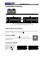
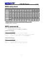
2002 MIDIator Systems UM2-BB User’s Manual MIDI OUT MIDI IN LOWER CONNECTOR A2 LOWER CONNECTOR A1 UPPER CONNECTOR B2 UPPER CONNECTOR B1 Version date: January 2002 1 UM2-BB Manual 2002 Table of Contents INSTALLATION SUMMARY............................................................................ 1 1) SELECT MODE AND CHANNEL ............................................................................1 2) CONNECT MIDI .................................................................................................1 3) CONNECT OUTPUTS ............................................................................................1 4) CONNECT POWER SUPPLY ..................................................................................2 INTRODUCTION................................................................................................. 2 INSTALLATION .................................................................................................. 2 REQUIREMENTS ......................................................................................................2 STAND-ALONE CONFIGURATION..............................................................................3 COMPUTER CONTROLLED CONFIGURATION .............................................................3 SETUP OF UM2-BB RELAY DRIVER ........................................................................4 CONNECTING WITH SCREW TERMINAL BLOCKS .......................................................5 OPERATION......................................................................................................... 6 INSTALLING THE UM2 SOFTWARE ..........................................................................6 SOFTWARE SETUP / DIAGNOSTICS ...........................................................................6 TROUBLESHOOTING ....................................................................................... 7 MECHANICAL SPECIFICATIONS ................................................................. 8 ELECTRICAL SPECIFICATIONS ................................................................... 9 MIDI CONNECTORS ................................................................................................9 INPUT/OUTPUT CONNECTORS ................................................................................10 MIDI NOTE CHART ......................................................................................... 11 MIDI COMMANDS............................................................................................ 11 ORDERING INFORMATION .......................................................................... 13 WARRANTY ....................................................................................................... 13 UM2-BB Manual 2002 Installation summary View of the front side of UM2-BB View of the back side of UM2-128-BB. Note that the upper connectors are not present in the UM2-64-BB. 1) Select Mode and Channel Because the UM2-BB does not have a mode or channel selector switch, it must be configured with the UM2 setup/diagnostics software (see page 6). 2) Connect MIDI (see page 9 for MIDI connector pinout) Connect MIDI IN to your source (i.e. MIDI OUT of computer, synthesizer, or other MIDI device). 3) Connect Outputs Connect your outputs to the 40pin headers in the back of the UM2 (see page 9 for pinout); optionally use our terminal adaptors (see page 5). 1 UM2-BB Manual 2002 4) Connect Power supply The UM2 requires 5 to 25 volts power supply; this is usually tapped from the main supply of your system. The negative of the power supply connects to the NEG pins of the 40-pin headers in the back of the UM2 (see page 9 for pinout); in most cases this is also ground of the system. We recommend that all NEG pins connect to the power supply negative; this is simplified if you use our terminal adaptors (see page 5). The positive of the power supply (5-25 volts) connects to the POS pins of the 40-pin headers in the back of the UM2 (see page 9 for pinout); usually, this is also the common to all the relays or switches in the system. The UM2 is a positive driver, it switches its outputs to POS; we recommend that all POS pins connect to the power supply positive; this is simplified if you use our terminal adaptors (see page 5). Introduction The UM2 is a MIDI decoder-driver: it receives MIDI messages and activates its outputs accordingly. The outputs can be used to drive organ pipe relays, lamps and other accessories. The UM2 has two internal partitions (the UM2-64 has only one). Each partition can be used independently as 64 outputs with each a different MIDI channel; or the two partitions can be combined into a single 128 output partition. Installation In the following sections, the examples show organ manuals (keyboards) and organ pipes (with relays) connected to UM2s. These are just the most common items used with the UM2; here are a few examples of what the UM2 can control: • Other musical instruments such as trumpets, xylophone, bells, drums, etc… • Electric lights, with or without relays, depending on voltage/power • Garage doors, alarm systems, model trains… • Other control applications involving a computer Requirements Power: the UM2 requires power from an external source; this is usually tapped from the main supply of your system. The voltage must be between 5 and 25 volts. The current used by the UM2 is less than 0.3 amps. MIDI: the UM2 receives MIDI, so it must be connected to a MIDI device; a computer, synthesizer… Computer: for diagnostics and software setup, a PC with Windows 95 or Windows 3.1 and a MIDI port is required. 2 UM2-BB Manual 2002 Stand-alone configuration The simplest system is the stand-alone configuration. In the following diagram, two UM1s are connected to manuals (keyboards), generating MIDI note messages from keys. Each UM1 corresponds to a UM2 with the same MIDI channel. Two UM2s are receiving the MIDI notes, driving the pipe relays. The limitation of this system is the one-to-one correspondence between keys pressed and pipes playing. Most organs need to be able to play multiple pipes for one key pressed. Another stand-alone example is the addition of ranks of pipes to a synthesizer system; those ranks would be equipped with relays and UM2s, connected to the MIDI OUT of the synthesizer. The pipes would play when the player sets the synthesizer’s output channel to the UM2’s MIDI channels. Computer controlled configuration This is the most powerful and flexible installation. All the MIDI note messages generated from the keyboards go through the computer before they control the relay drivers. 3 UM2-BB Manual 2002 This system allows recording and playback with sequencing software. Also, with the appropriate software each note message can be dynamically multiplied to activate several pipes in several ranks (implementing organ stops). Up to 16 UM2-BBs can be daisy chained on a single MIDI cable. In practice, we keep this number lower, because of the MIDI delay: every note message takes about one millisecond (0.001 sec) to be transmitted on the cable. This is not a problem on the console side, a single MIDI cable can keep up with ten fingers and two feet. But on the pipes side, if one key, for example, could activate 10 pipes, 5 keys pressed simultaneously can cause a delay of 0.050 sec, which is noticeable. If this applies to your system, you should have multiple MIDI output ports on your computer (we suggest 2 to 8 ranks of pipes per MIDI port, depending on the flow). Setup of UM2-BB relay driver The function of the UM2-BB is to receive MIDI note messages and drive its outputs accordingly. Choose partitions and transpose with the software setup (see page 6). The UM2 outputs are connected to relays, solenoids, valves, lights or other resistive/inductive loads (see specification page 7 for maximum load). The UM2 outputs are active high (positive driver), which means they act like a switch to the positive of the power supply (see diagram below); therefore the relays are connected between the UM2 outputs and the negative of the power supply. The positive of the power supply must connect to “POS” (see chart page 9). The negative of the power supply must connect to “NEG”, pin 1 of the 40-pin connectors; in most cases this is also ground of the system. We recommend that all POS and NEG pins connect to the power supply. If you are using our optional screw terminal blocks TERM1-128 or TERM164, those pins are already brought together to a single terminal. No “clamping” diodes are necessary, the UM2 contains diodes from NEG to each output. Vibrato output: The vibrato output is a slow oscillator whose frequency is controlled from zero to 10 pulses per second, by MIDI Modulation Bender messages (see page 11). This output can be used to control a door or device that modulates the sound. 4 UM2-BB Manual 2002 Connecting with screw terminal blocks Wiring is simplified with our optional screw terminal blocks TERM1-128 or TERM1-64, (or solder terminal blocks TERM1-S-128 or TERM1-S-64), which bring out all the input/outputs where they can connected directly to your wires. The diagram below shows screw terminals for 128 outputs, connected to a UM2. 5 UM2-BB Manual 2002 Operation When power is applied to the UM2-BB, its indicator LED should light up. Send it MIDI note messages and the corresponding outputs should turn on and off. The indicator LED should blink shortly every time the UM2-BB receives a note message. If it’s not working as planned, see troubleshooting, below. Installing the UM2 software To install the UM2 setup/diagnostics software on your PC, insert the diskette and run the file called “setup”. Software setup / diagnostics The UM2-BB should be configured with the UM2 setup/diagnostics software. Connect the UM2-BB’s MIDI IN to the PC’s MIDI OUT and the UM2-BB’s MIDI OUT to the PC’s MIDI IN (actually, several UM2-BB’s can be chained together as in the diagram page 3. You may be able to change the setup without removing the units from your installation). Power up the UM2-BB, and run the UM2 setup/diagnostics software. The software will attempt to find the UM2-BB(s) on your MIDI port, and will give you the choice between setup or diagnostics; just follow the instructions. 6 UM2-BB Manual 2002 Troubleshooting The UM2-BB does not have the display that the UM2 has, making it more difficult to troubleshoot; the only visual aid is the indicator LED. If you install a lot of UM2-BBs, contact the factory about getting a display unit that you can plug in just for diagnostic purposes. Symptom Probable cause Solution Indicator LED does not light up No power The UM2 software can’t find the unit Cables UM2-BB sometimes gets the wrong note, or ignores some notes MIDI cable interference Make sure you apply a positive voltage of 5 to 25 volts between POS and NEG of any of the 40 pin headers. Connect the UM2-BB’s MIDI IN to the PC’s MIDI OUT and the UM2-BB’s MIDI OUT to the PC’s MIDI IN. Test your PC’s MIDI port with a synthesizer if possible Try a shorter MIDI cable or one of superior quality, fully shielded. Move the UM2-BB away from motors, high current cables, high current relays/switches, CB radios. Check outputs for a direct short or a defective relay Electro-magnetic interference Indicator LED blinking on and off continuously Sending MIDI messages to the UM2-BB does not activate its outputs Output(s) shorted to the negative of the power supply or over current. Wrong MIDI channel Wrong connector No MIDI coming through cable Wrong mode of operation Notes out of range Output polarity One output does not respond Bad relay Short 7 The MIDI channel of the source should match that of the UM2-BB. If you have two partitions, the number displayed is the channel of partition A; partition B may have a different channel, according to the software setup (see page 6) MIDI OUT of the source should connect to MIDI IN of the UM2-BB Check your MIDI source by connecting a sound module or synthesizer, if you have one Check the mode of operation with software setup (see page 6). Depending on the mode of operation, you may call for transposition. Without transposition, the first output is MIDI note zero. Notes out of range do not activate outputs. The UM2-BB’s outputs switch to the positive side of the power supply, so the other side of the relay (or light or voltmeter) should be connected to the negative of the power supply. Check that relay, swap it for a known good one Check wiring of this output UM2-BB Manual Mechanical specifications 8 2002 UM2-BB Manual 2002 Electrical specifications Parameter Storage temperature Operating temperature Humidity (non-condensing) Min. -40 0 0 Max. 100 50 95 Units °C °C % Power supply The power for the UM2's internal circuits is provided at the 40-pin headers. Usually it is also the power supply of the user's external circuits. (i.e. 5 volts for a TTL interface, 12 volts or more for solenoid drive). Parameter Supply voltage Supply current Min. 4.75 Max. 25 0.3 Units Volts Amp Notes no load Driver Outputs The 128 open collector driver outputs are provided at the 40-pin headers. (The output drives low for a key on command). Active clamps enable driving solenoids or relays directly. Parameter On output voltage On output voltage duty cycle duty cycle duty cycle Typ. 1.6 1.8 Max. 1.8 2.0 100 50 30 Units Volts Volts % % % Notes at 100mA load at 350mA load all outputs at 100mA load all outputs at 200mA load all outputs at 350mA load Vibrato Output Output with same specs as driver outputs, provided at the 40-pin headers. A square wave of 0 to 10Hz is generated in response to "Modulation Bender" channel node message. A value of zero turns this output off. This output can be used to control a soleniod driven vibrato or "Leslie". MIDI connectors Pin # 1 2 3 4 5 MIDI IN MIDI OUT NO CONNECT NO CONNECT SHIELD SHIELD NO CONNECT NO CONNECT MIDI IN + MIDI OUT + MIDI IN MIDI OUT - Note: SHIELD is connected to ground through a 0.1µF capacitor, to avoid ground loop currents. 9 UM2-BB Manual 2002 Input/output connectors Pin # 1 2 3 4 5 6 7 8 9 10 11 12 13 14 15 16 17 18 19 20 21 22 23 24 25 26 27 28 29 30 31 32 33 34 35 36 37 38 39 40 Connector A1 NEG OUTPUT 0 OUTPUT 1 OUTPUT 2 OUTPUT 3 OUTPUT 4 OUTPUT 5 OUTPUT 6 OUTPUT 7 POS OUTPUT 8 OUTPUT 9 OUTPUT 10 OUTPUT 11 OUTPUT 12 OUTPUT 13 OUTPUT 14 OUTPUT 15 POS OUTPUT 16 OUTPUT 17 OUTPUT 18 OUTPUT 19 OUTPUT 20 OUTPUT 21 OUTPUT 22 OUTPUT 23 POS OUTPUT 24 OUTPUT 25 OUTPUT 26 OUTPUT 27 OUTPUT 28 OUTPUT 29 OUTPUT 30 OUTPUT 31 POS NO CONNECT VIBRATO (PWM1) POS Connector A2 NEG OUTPUT 32 OUTPUT 33 OUTPUT 34 OUTPUT 35 OUTPUT 36 OUTPUT 37 OUTPUT 38 OUTPUT 39 POS OUTPUT 40 OUTPUT 41 OUTPUT 42 OUTPUT 43 OUTPUT 44 OUTPUT 45 OUTPUT 46 OUTPUT 47 POS OUTPUT 48 OUTPUT 49 OUTPUT 50 OUTPUT 51 OUTPUT 52 OUTPUT 53 OUTPUT 54 OUTPUT 55 POS OUTPUT 56 OUTPUT 57 OUTPUT 58 OUTPUT 59 OUTPUT 60 OUTPUT 61 OUTPUT 62 OUTPUT 63 POS NO CONNECT RESERVED POS Connector B1 NEG OUTPUT 64 OUTPUT 65 OUTPUT 66 OUTPUT 67 OUTPUT 68 OUTPUT 69 OUTPUT 70 OUTPUT 71 POS OUTPUT 72 OUTPUT 73 OUTPUT 74 OUTPUT 75 OUTPUT 76 OUTPUT 77 OUTPUT 78 OUTPUT 79 POS OUTPUT 80 OUTPUT 81 OUTPUT 82 OUTPUT 83 OUTPUT 84 OUTPUT 85 OUTPUT 86 OUTPUT 87 POS OUTPUT 88 OUTPUT 89 OUTPUT 90 OUTPUT 91 OUTPUT 92 OUTPUT 93 OUTPUT 94 OUTPUT 95 POS NO CONNECT RESERVED POS Connector B2 NEG OUTPUT 96 OUTPUT 97 OUTPUT 98 OUTPUT 99 OUTPUT 100 OUTPUT 101 OUTPUT 102 OUTPUT 103 POS OUTPUT 104 OUTPUT 105 OUTPUT 106 OUTPUT 107 OUTPUT 108 OUTPUT 109 OUTPUT 110 OUTPUT 111 POS OUTPUT 112 OUTPUT 113 OUTPUT 114 OUTPUT 115 OUTPUT 116 OUTPUT 117 OUTPUT 118 OUTPUT 119 POS OUTPUT 120 OUTPUT 121 OUTPUT 122 OUTPUT 123 OUTPUT 124 OUTPUT 125 OUTPUT 126 OUTPUT 127 POS NO CONNECT RESERVED POS NEG is the negative of the power supply; in most cases this is also ground of the system and the common to all the relays in the system. We recommend that all NEG pins connect to the power supply. POS is the positive of the power supply (5-25 volts) for the UM2. We recommend that all POS pins connect to the power supply. 10 2002 UM2-BB Manual MIDI note chart Octave C C# D D# E F F# G G# 0 0 1 2 3 4 5 6 7 8 1 12 13 14 15 16 17 18 19 20 2 24 25 26 27 28 29 30 31 32 3 36 37 38 39 40 41 42 43 44 4 48 49 50 51 52 53 54 55 56 5 61 62 63 64 65 66 67 68 60 6 72 73 74 75 76 77 78 79 80 7 84 85 86 87 88 89 90 91 92 8 96 97 98 99 100 101 102 103 104 9 108 109 110 111 112 113 114 115 116 10 120 121 122 123 124 125 126 127 Shaded notes are the standard 61 note keyboard range. Additional shaded notes are the standard 88 piano keyboard range. Note 60 is middle C of keyboard A 9 21 33 45 57 69 81 93 105 117 MIDI commands Note: MIDI data numbers are hexadecimal. k is channel number 0-F; 0 is channel 1, F is channel 16 Channel voice messages: Bytes 8k nn vv 9k nn vv Ek vv vv Description Note Off event, running status accepted Note On event (vv = 0:Note Off) running status accepted Pitch bend change (lsb first) NOT IMPLEMENTED Channel Mode Messages: Bytes Bk 7B 00 Bk 01 vv Bk 40 vv Description All Note Off event Modulation Bender (Vibrato), zero is Off Sustain pedal, zero is Off, otherwise On 11 A# 10 22 34 46 58 70 82 94 106 118 B 11 23 35 47 59 71 83 95 107 119 UM2-BB Manual 2002 System Real-Time Messages: Bytes FF FE Description Reset system to power-up status. (including all notes Off) Active Sensing. Use of this message is optional. When initially sent, the receiver will expect to receive MIDI messages or another Active Sensing message at least every 300ms, or it will be assume that the connection has been terminated. At termination, the receiver will turn off all voices and return to normal (non-active sensing) operation. System exclusives (advanced users): The following are commands to output binary data to all outputs. Note that because sysex data are 7bit bytes, 8 bit data bytes are each split into 2 bytes: the first contains 7 most significant bits, the second contains the remaining bit. Dump Request (from host to UM2) Byte Description F0 7E kk 03 00 pp F7 Exclusive Non-Realtime Header kk = channel of partition A pp = 1 all 128 inputs pp = 2 partition A 64 outputs (use this for UM2-64) pp = 3 partition B 64 inputs EOX 12 UM2-BB Manual 2002 Ordering information UM2-128 UM2-64 UM2-128-BB UM2-64-BB positive output processor with 128 outputs in plastic enclosure UM2 with 64 outputs instead of 128, in plastic enclosure UM2 with 128 outputs, but no enclosure and no display UM2 with 64 outputs, but no enclosure and no display UM1-128 UM1-64 UM1-128-BB UM1-64-BB negative output processor with 128 input/outputs in plastic enclosure UM1 with 64 outputs instead of 128, in plastic enclosure UM1 with 128 outputs, but no enclosure and no display UM1 with 64 outputs, but no enclosure and no display UM1-128-P UM1-64-P UM1-128-P-BB UM1-64-P-BB double power UM1-128 double power UM1-64 double power UM1-128-BB double power UM1-64-BB TERM1-128, TERM1-64 TERM1-S-128, TERM1-S-64 CA40-17 screw terminal set for 128 outputs, 64 outputs solder terminal set for 128 outputs, 64 outputs 17 inch, 40 wire cable Warranty MIDIator Systems warrants for two years from the date of purchase this product if it does not perform satisfactorily due to defects caused by faulty materials or workmanship. Our obligation assumed under this warranty is limited to the repair, replacement or refund of this product, if it has not been misused. Disclaimer MIDIator Systems accepts no responsibility for damages resulting from the use of this product and make no warranty or representation, either express or implied, including but not limited to, any implied warranty of merchantability or fitness for a particular purpose. The product owner’s sole and exclusive remedy against MIDIator Systems shall be, at MIDIator Systems’ sole discretion, for (A) repair or replacement of defective product; or (B) repayment of the price paid for the product. No other remedy (including, but not limited to, incidental or consequential damages or lost profits, lost sales, injury to person or property, or any other incidental or consequential loss) shall be available to owner. In no event shall MIDIator Systems’ liability exceed amount paid for the product. 13 2002 MIDIator Systems MIDIator Systems P.O. Box 6065 San Diego, CA 92166-6065 Internet site: www.midiator.com Information E-mail: [email protected] support e-mail: [email protected] phone: 619-223-9000 fax: 619-223-9000