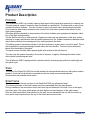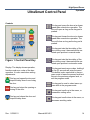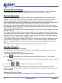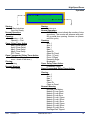
1
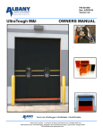
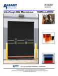
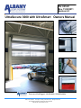
PN: 001451
Rev. 11/29/2011
Version 4.3
UltraSecure 3000 with UltraSmart Owners Manual
Doors are UltraRugged, UltraReliable, UltraAffordable.
Albany Door Systems - A Company of Albany International Corp. All Rights Reserved
975-A Old Norcross Road, Lawrenceville, Georgia 30046
800-252-2691 www.albanydoors.com
TABLE OF CONTENTS
Introduction
3
Product Description
4
Drawings
7
Inspection Plan
9
Safety Instructions
12
Troubleshooting
14
Maintenance
15
UltraSmart Control Pan-
17
Wiring
25
Wireless Safety System
31
UltraSmart Startup Procedure
32
Parts Diagram
37
ALBANY DOOR SYSTEMS
CONTACT INFORMATION
945-A Old Norcross Road, Lawrenceville, GA 30046
Phone: 800-252-2691
Fax: 770-338-5024
Technical Support & Aftermarket Parts:
Phone: 877-925-2468
Fax: 770-338-5034
www.albanydoors.com / [email protected]
1
Manual #001451
Version 4.3
High Speed Doors
Operation
INTRODUCTION
The contents of this manual are designed to help you operate and maintain Albany UltraLite™,
UltraFast™, UltraCool™, and UltraFreeze™ high speed doors.
DO NOT operate or perform maintenance on the high speed door unless you have read
through the instructions in this manual.
The safety alert symbol is used to identify safety information about hazards that can
result in personal injury. A signal word (DANGER, WARNING, or CAUTION) is
used with the safety alert symbol to indicate the likelihood and the potential severity
of injury. In addition, a hazard symbol may be used to represent the type of hazard.
DANGER indicates a hazard that, if not avoided, will
result in death or serious injury.
WARNING indicates a hazard that, if not avoided,
could result in death or serious injury.
CAUTION indicates a hazard that, if not avoided,
might result in minor or moderate injury.
CAUTION, when used without the alert symbol, indicates a situation that could result in damage to the
door.
NOTICE is used to inform you of a method, reference, or procedure that could assist with specific
operations or procedures.
Other symbols that may be used in this manual are:
Lock Out / Tag Out
Rev. 11/29/2011
Crushing
Fire
Manual #001451
Shock
Read Manual
2
Product Description
Principle
The UltraSecure 3000 is a vertically opening high-speed rolling metal door primarily for external use.
The door panel is made of aluminum slats connected to a special belt. The slats wind on up to three
variable sized disc modules. They do not stack or wind onto each other, which protects the slats
from excessive wear and produces smooth, contact-free frictionless operation that allows for the
high opening speed.
Absorbing profiles attached to the perimeter of the discs enables quiet operation and dampen vibration of the slats during winding.
The flat belt functions as a pulling device. Hinges and rollers are not necessary in this door system,
allowing for longer maintenance intervals and increased door life. Rubber connections between each
slat prevent moisture from entering and from settling between the slats.
The pulling power is transferred equally to the disc modules by a gear motor via a drive shaft. This is
also supported by tensioned springs located within the side columns. The door closes with assistance from the weight of the panel.
The panel moves vertically within special guide rails located in the side frames.
The door may be opened manually in the event of a power outage by releasing the brake via the
side column mounted egress lever.
The UltraSecure 3000 is equipped with a wireless electric reversing edge and inline safety light curtain photo eyes..
Slats
The slats of the Rapid Roll 3000 are double walled extruded anodized aluminum with rubber seals in
between. Each slat is individually connected and can be easily removed and replaced.
Window slats are available as an option.
Side Frame
The side frames and cross sections of the Rapid Roll 3000 are galvanized steel.
The various elements of the side frames come pre-assembled from the manufacturer.
During installation, the side frames must first be set up and fastened to the wall / floor in the upper
and lower area. The upper width gauge can help define the exact distance of the side frames.
After the side frames have been secured to the wall, the pre-assembled top roll with the rolled-up
door panel must be placed onto the top of the side frames and secured.
3
Manual #001451
Version 4.3
High Speed Doors
Operation
Control Unit
The UltraSecure 3000 is operated by a frequency converter control unit, which enables smooth acceleration and deceleration of the door. The maximum opening speed is 80 in/sec depending on
door size. The door’s closing speed is approximately 24 in/sec.
Manual Operation
During maintenance work, or in the event of a power outage, the door may be opened manually by
releasing the brake via the side column mounted egress lever. The door opens partly by itself after
the brake is released, and may be opened further by manually pushing the door panel upwards.
Electric Safety Devices
The door is equipped with various safety devices, which are partly based on radio – photocell systems.
Electric safety features
The UltraSecure door utilizes a minimum of two safety features. This is comprised of safety photocells and electric reversing edge.
Self-monitoring Drive Unit
The temperature of the drive unit is regulated by a thermal switch, which disrupts the power supply
of the drive unit upon overheating.
Testing the Safety Systems
Before each downward movement an internal “self-testing” of the photocells and the control unit is
made automatically (Safety classification 2 according DIN EN 954-1 "Safety relevant parts of control
units"). If a fault is detected, disruption of the power supply to the control unit occurs immediately.
The safety switches work as a closing unit and are in continuous operation.
Additional Safety Systems
Depending on the kind of application it may be advisable to utilize additional sensors for safety reasons. This will be especially valid for doors with frequent pedestrian traffic or doors less than 10 feet
high due to limited optical awareness of a closing door by the user.
Albany Door Systems offers various additional safety systems for fast running doors such as; motion
sensing detectors, floor loops, etc. We suggest individual consultation with an Albany Door Systems’
representative at the application site .
Rev. 11/29/2011
Manual #001451
4
Mechanical Safety Devices
Springs are situated in separate chambers serving as a weight balancing system. The springs are
enclosed and protected by metal covers.
The door has a multi independent weight balancing system. Disengagement of the drive unit brake
will not lead to a sudden drop of the door panel.
For doors with a height less than 8 feet a top roll
cover is absolutely necessary according to valid
regulations.
Drive Unit
An electric drive unit operates the UltraSecure 3000. The drive unit is installed in the upper area of
the door, not within reach from the floor, and has a vibration dampening attachment. The drive unit
may be positioned on either the left or right hand side, according to customer requirements.
The same drive is used for all varieties of door height. The frequency converter control unit will be
operable with various parameters depending on the size of the door.
The door may only be operated with an original
drive and control unit made by the manufacturer
of the door.
Technical Data
Door principle:
Running direction:
Application:
Available sizes:
Max. opening speed:
Closing speed:
Application:
Drive:
Connecting voltage:
Motor performance:
Control unit:
Control voltage:
Motor protection:
Side frame:
Door curtain:
Pulling device:
Sound pressure level:
Wind resistance:
Door measurements and
installation space:
5
rolling metal
vertical
fast running exterior (primarily) or interior
W min.: 2.58 ft (1250mm) W max.: 16.4 ft (5000mm)
H min.: 6.50 ft (2500mm) H max.: 16.4 ft (5000mm) Height
steps: 1/2 inch (125mm)
80”per sec (2.5 m/s)
approx. 24”per sec (0.7 m/s)
inner side of exterior wall
electric
3/(N)/PE 230/400 V ±10%, 50/60 Hz
1.1 kW
UltraSmart Control (frequency converter control unit)
24 V DC
IP55
galvanized steel
double walled anodized aluminum
flat belt with integrated steel ropes
70 dB A
110 m/h, classification 3 (EN 12424)
see enclosed drawing
Fixing points:
see enclosed fixing point plan
Technical changes to the door and the manual can occur.
If you have questions please consult with the factory.
Manual #001451
Version 4.3
High Speed Doors
Operation
UltraSecure 3000 10’ high up to 16’ high
Rev. 11/29/2011
Manual #001451
6
UltraSecure 3000 up to 10’ high
7
Manual #001451
Version 4.3
High Speed Doors
Operation
Inspection Plan
Observe the safety notices within the operation manual. Power to the door must be shut off prior to
inspection of any door component.
Installation
fixings
Before checking
the following mentioned components the cover in front of the
spring housing and eventually the existing top roll and motor cover must be
dismantled.
Drive unit
Check retainer of the torque support and buffer.
Check function of brake release lever.
Check self-opening/manual opening/egress
Drive shaft
Check flange bearing retainers of drive shaft.
Check retainer of the spiral disk on the shaft.
Check condition of sound isolation or black dampener profiles on the spiral disks.
Exchange of flat lifting belts.
Door leaf
Check surface of lamellas/slats for grinding and signs of damages.
Check exact position of lamella sealing.
Check fixing of lamellas on pulling device.
Check solid position of lamella adapter/endplates.
Guiding rails
Check for wear and tear on guidingrails, especially in the area of funnel (<4MM)
Side columns and lintel profile
Check fixing and condition of the profiles as well as fixing at the wall
Check condition and fixing of trailing chain for cable if equipped
Check condition and installation of springs and spring fixing.
Check leaf tensioning system if equipped.
Exchange rubber cable/bungee cord if equipped
Clean optic of photocells.
Counter balance system
Exchange springs H<3m.
Exchange springs H>=3m.
Check condition and fixing of the spring belts.
Lubrication of roller chain (only RR3000R).
Control Box and additional components (like safeties & actuators)
Check completeness of wiring diagram.
Check main switch/CEE-plug and control box lock.
Check fixing of control panel
Check function of staionary and/or pre-runing photocells
Verify stopping position of limits
Check function of electric reversing edge if equipped
Rev. 11/29/2011
Manual #001451
Annually or 100,000 cycles.
Annually or 100,000 cycles.
Annually or 100,000 cycles.
Annually or 100,000 cycles.
Annually or 100,000 cycles.
Annually or 100,000 cycles.
Annually or 100,000 cycles.
500,000 cycles.
Annually or 100,000 cycles.
Annually or 100,000 cycles.
Annually or 100,000 cycles.
Annually or 100,000 cycles.
Annually or 100,000 cycles.
Annually or 100,000 cycles.
Annually or 100,000 cycles.
Annually or 100,000 cycles.
Annually or 100,000 cycles.
500,000 cycles.
As necessary.
500,000 cycles.
250,000 cycles.
Annually or 100,000 cycles.
Annually or 100,000 cycles.
Annually
Annually
Annually
Every 6 months or 25,000 cycles
Annually or 50,000 cycles.
Every 6 months or 25,000 cycles
8
Safety Instructions
Area of Application and Classified Use
Unless explicitly described otherwise, Albany Door Systems’ doors are developed and tested for use
under normal operating conditions. For an application with special conditions (for example; onesided permanent load with temperatures, excessive pressure or special environmental conditions,
etc.) contact Albany Door Systems.
The door is defined primarily for use in industrial buildings.
As an exterior door with respective resistance against wind pressure and weather conditions it
opens with a speed especially suited for high frequency vehicular traffic ensuring a smooth transport
flow.
The door may also be applied as an interior door.
Duty of Care
The door has been designed and manufactured under consideration of a risk analysis according
careful selection of valid norms and further technical specifications. The system meets status of
technique and ensures the highest level of safety.
All necessary measures and precautions must be observed in order to achieve the high safety
standard. It is the duty of the door operator to plan the respective measures and check the door’s
performance. Please read the user manual carefully and keep it in a safe place for future use.
The operator is liable to ensure that:
Installation, initial operation, inspection, maintenance, repair work and dismantling are made only
by manufacturer personnel or manufacturer trained and qualified personnel.
Only sufficiently trained, qualified and authorized personnel should operate the door system.
The door is to be used only in accordance with the classified purpose (see above).
The door is to be operated only in a perfectly functioning state and that the safety features are
regularly checked for orderly operation.
The user manual is kept at the site of the door for future use and is in readable condition at all
times.
The operating personnel are continuously trained with regard to working safety and operating instructions and especially the herein-contained safety instructions.
All safety and caution notices affixed to the door will not be removed and are kept in readable
condition.
9
Manual #001451
Version 4.3
High Speed Doors
Operation
General Safety Advice
Please read the user manual carefully and keep it easily accessible for future use.
Always follow the safety instructions mentioned in the user manual.
Do not use this door for purposes it is not intended for. This user manual must also be transferred upon the transfer of this door to third parties.
The use of the emergency lever may lead to a partial self-opening or closing of the door.
The door panel may be opened upon failure of the electrical drive by disconnecting the brake using the emergency disconnect lever.
Do not put your hands on the side frames of the door during operation.
Lingering of persons in the working area of the door should be avoided. Existing man doors
should be used for pedestrian traffic.
Should it be necessary for pedestrians to utilize the door opening, they should walk through at a
normal pace.
Keep the immediate area of the door free of debris or refuse, which could cause accidents.
Do not climb on the door.
The power to the door must be shut off at the main switch and must be secured against returning
to the “on” position prior to working on the door.
Upon damage to the door (mechanical or electrical), the power must immediately be turned off.
This is especially valid when damage has occurred to the electrical cables or wiring.
The door must only be operated within the parameters of the defined voltage or net frequency.
Use only equipment or additional features which are authorized by the manufacturer of the door.
Operating the door during excessive wind pressures may be dangerous.
Safety instructions must be observed without exception, not only the general safety instructions but
also the special notices mentioned in other chapters of the manual
Additional Advise
Please call 800-252-2691 for further information about this product or about Albany Door Systems’
complete product line.
Rev. 11/29/2011
Manual #001451
10
Troubleshooting
To avoid damage to the door or injury to personnel during repair of malfunctions or errors, the following instructions should be carefully observed:
Only trained personnel should accomplish Work.
Turn off the power at the main switch prior to performing any work.
Secure the main switch against being turned on again by locking it or by having a second person present.
Secure the door’s operating area.
Read "Safety Instructions".
In the event the repair cannot be made or assistance is required, please contact the customer service department of the supplier or manufacturer of the door.
Mechanical Malfunctions
Malfunction
Door opens
independently
Manual opening not
possible
Drive not functioning
Curtain unwraps
11
Possible Causes
Necessary Measures
Brake at the drive defective
Replace the brake
Brake incorrectly adjusted
Adjust the brake
Counterbalance is oversized
Call customer service
Counterbalance defective
Replace the counterbalance device
Bowden cable hanging off or too loose
Check correct position and tension
of the bowden cable
Brake blocking
Call customer service
Power supply is off
Connect the door to the power
Electrical connections defective
Check electrical connections
Safety device is defective
Replace the safety device
Door not correctly installed
Call customer service
An object was rolled up
Close the door and check for enclosed object
Manual #001451
Version 4.3
High Speed Doors
Operation
Electrical Malfunctions
For repair of electrical malfunctions see the error code manual at the appendix of the user manual
instructions.
Malfunction
Possible Causes
Door not functioning
Door does not close
Door closes only
with next impulse
Necessary Measures
Power supply is off
Check power supply and fuse
Safety device damaged
Check control unit and replace the fuse
Main switch off
Turn (main switch) switch on
Stop-circuit interrupted
Check stop circuit. Unused stop inputs
must be bridged in accordance with the
circuit diagram.
Up impulse permanently activated
Test impulse actuator
Photocell interrupted or disconnected Test safety devices
Toggle circuit adjusted
Check adjusted control function
Maintenance
Customer Service
In the event maintenance or repair is required, please contact the supplier or the
manufacturer of the door.
Albany Door Systems
975-A Old Norcross Rd
Lawrenceville, GA 30046
Main Telephone: 800-252-2691
Customer Service Telephone: 877-925-2468
Service & Parts Fax: 770-338-5034
Rev. 11/29/2011
Manual #001451
12
Inspection and Maintenance
Maintenance and inspection work must only be performed by manufacturer trained authorized personnel.
Before beginning the above-mentioned work the power must be disconnected by turning off the
main power switch and locking it. The control unit must be checked to determine there is no power
to it with the appropriate device. All ladders, scaffoldings, or similarly used equipment should correspond with valid safety regulations.
The area around the door must be blocked for traffic. Any spilled lubricating oil, tools and other material should be removed from the floor when work has been completed.
The necessary intervals, check-ups and instructions for such work are documented in the
“Inspection Schedule“ (see Appendix).
Cleaning
Cleaning and Maintenance of the Panel
Do not use any glass cleansing liquids (contents may be
corrosive)
Never use score cleansers, scrapers, razor blades, spatulas, etc.
Clean with warm water, a small dose of mild plastic cleanser and a soft cloth.
Cleaning and Maintenance of the Side Frame
Dust may be removed with a soft cloth. Harder dirt may be removed with water and general liquid
cleanser.
Grease or oil on the metal surfaces may be removed with solvent containing cleanser.
Do not use a high-pressure cleaning machine.
Clean Door Area
The floor around the side frames may become dirty with lubricants, etc. following maintenance
work. This must be removed quickly.
Tensioning the Panel
The door is furnished with a panel tension system. The bottom profile is pulled down on both sides
by means of a rope. The ropes guard a secure run during closing of the door especially during
heavy wind force.
13
Manual #001451
Version 4.3
UltraSmart Control Panel
High Speed Doors
Operation
Controls
This key pad opens the door at a slower
speed than normal door operation. The
door will open as long as the key pad is
pushed.
This key pad closes the door at a slower
speed than normal door operation. The
door will close as long as the key pad is
pushed.
This key pad sets the time delay of the
door closing once it has reached the selected open position in manual mode.
Figure 1 Control Panel Key
This key pad sets the time delay of the
door closing once it has reached the selected open position in automatic mode.
Display: The display shows operation,
functions and error codes of the door
operation. It is also used when setting
adjustments.
This key pad resets error codes, holding it
for five (5) seconds will enter the menu.
This button is also used while in the program mode to leave the present level and
return to the previous program level, or
exit the program mode.
This key pad opens the door and
stops the delay timer from closing
the door.
This key pad stops the opening or
closing of the door.
This key pad closes the door and
stops the delay timer.
Rev. 11/29/2011
This key pad is used to select menu options while in the program mode.
This key pad scrolls up in the menu, or
increases a setting value.
This key pad scrolls down in the menu, or
decreases a setting value.
Manual #001451
14
Control Panel Display
The display on the front of the control panel shows two lines of information. The top line displays
system status and the second line displays details of the function or specifics of errors.
Normal Operation
During startup the display will show the software version programmed into the control panel and
whether or not the door is ready for normal operation. Once the software has booted the door is
ready for operation, the top line will display “Door Ready” unless there is an error detected.
During normal operation the top line will display the current door status, with respect to movement or
timers. “Door Ready” will be displayed while in standby mode, if no errors are present.
The second line on the display will show the activator name for the function, or the safety device
that triggered an action. The activator can be a manual input signal from the light curtain or reversing
edge, or a breakaway switch input.
There can be normal operation with the top line displaying “Door Ready” and the display second line
showing a warning.
The “Open: Delay timer Active” display is shown when the door is open and a timer function is operating to delay the door from closing. A “Preventer” code may be displayed if a condition exists to prevent the door from closing such as a disruption of the light curtain or a door bottom edge breakaway.
The timer is re-armed if a “Preventer” condition exists.
If any of the warnings shown on page six (6) except for “RevEdge Was Tripped” is displayed, please
contact Albany Door Systems for diagnosis and repair. If the bottom line displays “RevEdge Was
Tripped” it indicates that the door is open due to a reversing edge trip during the previous close cycle.
The diagram show on page six (6) shows examples of normal operation displays.
Operator Service
Changing the Door Closing Time Delay
In normal operation the Auto time delay selects the delay time before closing the door once it has
reached the selected open position.
To increase the time that the door waits before closing:
Press
the time delay will be displayed in seconds at a flashing cursor. If no key pad is
pressed the controller will automatically return to normal operation after approximately four (4)
seconds.
Press the
or
to change the time delay in second intervals.
After four (4) seconds the display will return to normal operation and the time will be stored in
memory. If the time is set to “00” with the Man 1 Close Delay the door will remain open until this activator is triggered.
Seating the Door in the Tracks
This function is not applicable for the UltraSecure door. Breakaway upon impact is not possible.
15
Manual #001451
Version 4.3
High Speed Doors
Operation
Line One (1) Text
Line Two (2) Text
Startup:
R-Bac Industries
Door Not Ready
Normal Operation:
Door ready
Opening:
Opening — Full
Opening — Part
Open: Delay Timer Active
Auto1 Close Delay
Auto2 Close Delay
Man1 Close Delay
Man2 Close Delay
DTC Timer
Open Commanded :Delay Timer Active:
DTO Timer (Display shown during a
count - down of the timer.)
Closing:
Closing
Normal: Warning
Door Ready
Startup:
Version n.m
Normal Operation:
0000000 The zeros indicate the number of door
operations. The counter will advance with each
full or partial door opening. Version n.m (shown
until first cycle)
Opening:
Auto 1
Auto 2
Man 1
Man 2
Open Pb
Open On Panel
Photo 1 (Front)
Photo 2 (Rear)
Reversing Edge
Breakaway
Open: Delay Timer Active:
(Preventer, if any)
Open Commanded :Delay Timer Active:
Closing:
Auto 1
Auto 2
Man 1
Man 2
Close Pb
Close on Panel
Normal: Warning
Encoder Low Battery
Module D Loop Open
Module D Loop Short
Module D Loop Error
Module D Loop1 Open
Module D Loop1 Short
Module D Loop1 Error
Module D Loop2 Open
Module D Loop2 Short
Module D Loop2 Error
RevEdge Was Tripped
Rev. 11/29/2011
Manual #001451
16
Adjustments
Door Limit Adjustments
Door limit adjustments are used to set four heights that the door opens and closes to. There are four
(4) heights that the operator can set; Closed Limit, Full Open Limit, Partial Open Limit, and Break
Away Reset Limit. The Closed Limit should always be checked for correct height or set before the
other limits are set. When any limit is set all of the limits should be checked or set.
Closed Limit
Used to set the fully closed position of the door. The door controller uses this position as the “zero”
position to establish the height that the door moves to for two (2) open positions and the break away
position. The Open, Partial, and Break Away limits are all relative to the Closed Limit. If the closed
limit is reset to a different position, all the other settings will change relative to the new Closed Limit
Setting.
Full Open Limit
Used to set the height that the door opens fully to.
Partial Open Limit
Used to set the height that the door opens to if it is programmed for a lower opening in addition to
the fully open position.
17
Manual #001451
Version 4.3
High Speed Doors
Operation
Periodic Maintenance Continued…
Quarterly Inspection
1. Perform daily inspection.
2. Check all mounting hardware and verify that all nuts and bolts are tight. Hardware includes: wall
anchors, cover hardware, motor mounting hardware, and bearing bolt nuts.
3. Check the break away function by performing the following steps:
Stop the door so the bottom rail is between waist and chest high.
Push the bottom bar out of one of the side columns.
Press the open key pad and verify that the door opens to the break away opening height
and that the bottom bar centers in the side rails.
Press the close key pad and verify that the bottom rail is centered and the door closes fully.
4. Inspect all side and top weather seals for wear or damage.
Troubleshooting
DISPLAY OR DOOR
Problem
Possible Cause
Corrective Action
No control or VFD
display.
Loss of main power.
Check with meter across L1-L2,L2-L3,L1-L3
Blown Fuse
Check with Meter:
Across 1L1-1L2, 1L2-1L3,1L1-1L3
Across 2L1-2L2, 2L2-2L3, 2L1-2L3
Loss of power.
Check with meter across 1L1-1L2 at control
transformer.
Blown fuse.
Use meter to check for 24V between wired H_
terminals on top of transformer and between
XF and X2 on bottom of transformer.
No display or LED’s
light on module panel.
E stop jumper loose or miss- Verify that jumper is between 1A and 1B on
ing.
terminal strip of module board.
Door will not open.
Rev. 11/29/2011
If E stop button present.
Check to see if E stop button activated.
No input signal at module A
Check activation input by pressing corresponding test button, LED should light and door
open. If door opens: faulty activator or wiring to
module. If door does not open by test button:
faulty module.
Manual #001451
18
Trouble Shooting Continued...
DISPLAY OR DOOR
Problem
Possible Cause
Corrective Action
Door does not close.
Held open by safety input or ac- Check display readout. Check
tivator input.
for lit LED on modules A and B.
Remove corresponding wire on
module A. For lit LED-if door
closes: faulty activator.
If LED stays lit and door stays
open: faulty module.
Held open if loop installed.
Check loop module for lit LED.
Remove loop wires from module
terminal strip.
If door closes: faulty loop wire.
If door remains open and LED
stays lit after removal of loop
wires: faulty module.
Door does not open or close.
Reversing edge activated.
Check display reset.
Check for bad wire connection.
Check that edge is not pinched.
Breakaway activated.
Check display reset.
Check for bad wire connection.
Check that edge is not pinched.
Brake not disengaging.
Check power at terminals 5 and
6 below module C for 24 VAC.
Check power at terminals B1
and B2 for 3 phase power.
No encoder change, no position Door jammed: clear jam
change.
Broken drive shaft.
Call manufacturer.
Encoder com loss of signal.
19
Manual #001451
Check for loose connections or
broken cable.
Check for encoder mounting.
Call manufacturer.
Version 4.3
High Speed Doors
Operation
Trouble Shooting Continued...
Light Curtain
Problem
Possible Cause
Corrective Action
Red alarm LED on.
Transmitter disabled no synchronization signal.
Check power supply and cable
green LED should be on at all
times.
Yellow LED flashing.
Sever electrical interference.
Remove cables from high voltage.
High ambient light.
Check and adjust alignment of
transmitter and receiver.
Yellow LED always off.
Receiver cannot see transmitter. Remove obstruction.
No green LED.
Loss of 24 VDC
Check across terminal 1 and 4
on module B:
Remove wires from terminal 1,
2, 3, 4.
If 24 VDC present at terminal 1
and 4: isolate faulty light curtain.
If 24 VDC not present at terminal 1 and 4 after removal of
wires: faulty module.
Motor Drive Fault
To clear a fault press the stop key, or cycle power.
Problem
Possible Cause
Corrective Action
Motor drive fault
F3 power loss.
Check incoming power.
F4 undervoltage.
Check incoming power for low
voltage or power interruptions.
F5 overvoltage
Check for incoming power.
F6 motor stalled.
Increase accel time or reduce
load so drive does not exceed
set current in A089.
F8 heatsink overheat.
Check for blocked or dirty heat
sink fins, check fan.
F13 ground fault.
Check the motor and external
wiring for the drive output terminals for a grounded condition.
Rev. 11/29/2011
Manual #001451
20
Trouble Shooting Continued...
Motor Drive Fault
Problem
Possible Cause
Corrective Action
Motor Drive Fault
F38 phase U to ground.
F39 phase V to ground.
Check wiring between drive and
motor. Check motor grounded
phase.
Contact manufacturer.
F40 phase W to ground.
F41 phase UV short.
F42 phase UW short.
F43 phase VW short.
F70 power unit.
21
Manual #001451
Check the motor and drive output terminal wiring for shorted
condition.
Contact manufacturer.
Recycle power. If fault does not
clear, call manufacturer.
Version 4.3
High Speed Doors
Operation
WIRE
STRIP GAUGE
MOTOR WIRING
¼”
8"
6"
¾”
MOTOR WIRE CONDUIT
BRAKE WIRES
DRILL ONLY INTO BOTTOM OF BOX
USE MINIMUM ¾” CONDUIT
¼”
T2
MG
T1
SEPARATE
FOIL SHIELD
MG
SEPARATE
FOIL SHIELD
6"
T3
B1
MG
B2
NOTE:
MOTOR WIRES
TO CHANGE DIRECTION OF MOTOR ROTATION – SWITCH T1 AND T2
ENCODER WIRING
WIRE
STRIP GAUGE
¼”
¾”
LOW VOLTAGE CONDUIT
ENCODER, SAFETY, ACTIVATION
4"
DRILL ONLY INTO BOTTOM OF
BOX
USE MINIMUM ¾” CONDUIT
TB2
TB3
TB1
TB1
TB4
Rev. 11/29/2011
Manual #001451
22
ACTIVATION WIRING
N
TOP 3 TERMINALS
H
NEXT 5 TERMINALS
MANUAL
ACTIVATORS
MODULE - A
TB2
1
2
3 4 5
CONNECT AS “NORMALLY OPEN”
6
H
MODULE - A
TB3
HERKULES™
MOTION SENSOR
H
BROWN
GREEN
N
WHITE
PINK
Connect GRAY
for Person
Detection
1
2
3 4 5
6
GRAY
RED
Connect RED for
Vehicle Detection
MODULE - A
TB3
FALCON™
MOTION SENSOR
H
1
2
3 4 5
6
GREEN
RED
WHITE
N
BLACK
REMOTE
CONTROL
H
H
N
MODULE - A
TB2
1
GRAY
2
3 4 5
6
GRAY
RED
BLACK
TB3
1
2
TB4
3 4 5
MODULE - D
6
LOOP DETECTOR
(optional)
23
Manual #001451
Version 4.3
High Speed Doors
Operation
Rev. 11/29/2011
Manual #001451
24
25
Manual #001451
Version 4.3
High Speed Doors
Operation
Rev. 11/29/2011
Manual #001451
26
27
Manual #001451
Version 4.3
High Speed Doors
Operation
ENABLING THE WIRELESS SAFETY SYSTEM
If the door is equipped with Albany’s Wireless Safety System (indicated by the lack of a coil cord),
the following steps must be taken to initialize the communications:
1.
2.
3.
4.
5.
6.
Locate the RF transceiver on the bottom slat (shown to left)
Remove the cover and locate the RFID number on the pull
strip.
Setup the UltraSmart™ Controller according to the procedure
below:
Hold the circuit board with one hand and pull out the strip.
Replace the cover and 4 screws.
Test the system.
UltraSmart™ Controller Settings
Press and hold
until “LIMIT SETUP” is shown on the display
Press
until “WIRELESS SETUP” is shown; Press
Press
until “BOTTOM BAR ID” is shown; Press
Change the number to the RFID number on the bottom bar label using
Press
to store the value and press
and
until “DOOR READY” is displayed
Thoroughly test the system to determine if all sensors/switches are functioning properly. Make
sure you can answer “yes” to the following questions:
Does the door reverse when the reversing edge is tripped upon closing?
If you cannot answer “yes” to all the above questions, check all wiring connections and ensure
the RFID is set to the same number that is labeled on the wireless bottom bar module.
Rev. 11/29/2011
Manual #001451
28
UltraSmart™ STARTUP PROCEDURE
Albany’s UltraSmart™ control system is designed to accommodate numerous option modules and future technological advances. This manual will
address necessary settings for the standard options; however, optional
modules and special applications may require additional steps to be taken
for proper setup. Refer to the control schematic shipped inside the panel
enclosure for additional electrical and setup details.
SETTING DOOR LIMITS
NOTE: SAFETY DEVICES WILL PREVENT THE DOOR FROM CLOSING IF ACTIVATED DURING
SETUP
ENABLE THE WIRELESS SYSTEM (IF EQUIPPED) PRIOR TO SETTING DOOR LIMITS
1) Press and hold
until “LIMIT SETUP” is shown on the display; Press
2) “CLOSED LIMIT” should be displayed; Press
3) Use
4) Press
5) Use
6) Press
7) Use
and/or
to bring the door to the full closed position; Press
“FULL OPEN LIMIT” should be displayed; Press
and/or
to bring the door to the full open position; Press
“PARTIAL OPEN LIMIT” should be displayed; Press
and/or
to bring the door to the partial open position or set the
same as the full open position if not used; Press
8) Press
29
until “DOOR READY” is displayed
Manual #001451
Version 4.3
High Speed Doors
Operation
The Open and Partial Limits are all relative to the Closed Limit. If
the Closed Limit is reset to a different position, all other limit settings will change relative to the new Closed Limit setting.
SETTING SYSTEM OPTIONS
1) Press and hold
2) Press
Use
until “LIMIT SETUP” is shown on the display; Press
until “SYSTEM OPTIONS” is shown; Press
and/or
to cycle through the available options; Press
and/or
to change the value; Press
to edit that
option.
Use
3) When finished—press
to store that value
until “DOOR READY” is displayed
SETTING TIMERS
1) Press and hold
2) Press
Use
until “LIMIT SETUP” is shown on the display; Press
until “SET TIMERS” is shown; Press
and/or
to cycle through the available options; Press
and/or
to change the value; Press
to edit an
option.
Use
3) When finished—press
Rev. 11/29/2011
to store that value
until “DOOR READY” is displayed
Manual #001451
30
Instructions for Using Over-Travel Brake System.
About the Over-Travel Brake System
Your UltraSecure door is fitted with an over-travel
brake system to stop your door in a controlled manner in the event a condition should arise leading to
the door traveling past its upper limits. The system
terminates the open command and immediately engages the gear motor brake. But, due to the high rotational inertia of the barrel, an additional mechanical brake is utilized, catching the bottom slat for a
controlled deceleration. This addendum shows how
to reset the system to get your door operational. Prior to resetting the brake, you must lower the door to
the open position. Follow electrical instructions for
lowering process.
Notice: Inspect the door
for damage prior to putting
it back in service. Repair
door where necessary.
Failure to perform inspections and repairs can lead
to personal injury, property
damage or death.
If an over-travel event occurs, hooks mounted on the
bottom slat engage the brake yoke. The yoke is then
dragged through the pair of brake clamps finally coming to rest at the end of the clamp (fig 2.).
Fig 2. Safety brake deployed.
31
Manual #001451
Version 4.3
High Speed Doors
Operation
Resetting the Brake
To reset the brake, first loosen the clamp
screws (Fig 3) so that you can move the
yoke up and down easily.
Clamp
Fig 3.
Move the yoke to the bottom of
the clamp and retighten clamp
Fig 4. Yoke at bottom position.
Rotate yoke rest to a
horizontal position and
snap yoke into pocket.
Reset door limits.
Your door is now
ready to go back into
service.
Rev. 11/29/2011
Manual #001451
32
Electrical Operation Instructions
When the over-travel mechanism has been engaged, the power to the control system will be
disabled. The following procedure will reset the electrical system:
1. Turn the power off (wait 20 seconds) and then back on using the
main panel disconnect switch.
2. With the power on, open the control panel and locate the over-travel
sensor relay (shown here with teal override button).
3. Press and hold the teal override switch on the sensor relay and jog
the door down using the “Emergency Jog Down” button on the face
of the C-Module.
4. Once the door has been lowered below the normal open position,
stop.
5. Reset the door limits as follows:
1) Press and hold
until “LIMIT SETUP” is shown on the display; Press
2) “CLOSED LIMIT” should be displayed; Press
3) Use
4) Press
5) Use
6) Press
7) Use
and/or
to bring the door to the full closed position; Press
“FULL OPEN LIMIT” should be displayed; Press
and/or
to bring the door to the full open position; Press
“PARTIAL OPEN LIMIT” should be displayed; Press
and/or
to bring the door to the partial open position or set the
same as the full open position if not used; Press
8) Press
33
until “DOOR READY” is displayed
Manual #001451
Version 4.3
High Speed Doors
Operation
Rev. 11/29/2011
Manual #001451
34
35
Manual #001451
Version 4.3
High Speed Doors
Operation
Rev. 11/29/2011
Manual #001451
36
37
Manual #001451
Version 4.3
High Speed Doors
Operation
Rev. 11/29/2011
Manual #001451
38
39
Manual #001451
Version 4.3
High Speed Doors
Operation
Rev. 11/29/2011
Manual #001451
40
41
Manual #001451
Version 4.3
Albany Door Systems - A Company of Albany International Corp. All Rights Reserved
975-A Old Norcross Road, Lawrenceville, Georgia 30046
800-252-2691 www.albanydoors.com