1
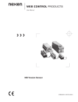
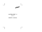
USER
UltraBlock
GUIDE
E
!
T ST
N
A IR
T F
R E
O
M
P
IM AD
R
™
N O T I C E
No part of this manual, including the products and software described in it, may
be reproduced, transmitted, transcribed, stored in a retrieval system, or translated into any language in any form or by any means, except documentation
kept by the purchaser for backup purposes, without the express written permission of Digital Intelligence, Inc. (“DI”).
DI PROVIDES THIS MANUAL “AS IS” WITHOUT WARRANTY OF ANY
KIND, EITHER EXPRESS OR IMPLIED, INCLUDING BUT NOT LIMITED TO
THE IMPLIED WARRANTIES OR CONDITIONS OF MERCHANTABILITY OR
FITNESS FOR A PARTICULAR PURPOSE. IN NO EVENT SHALL DI, ITS
DIRECTORS, OFFICERS, EMPLOYEES OR AGENTS BE LIABLE FOR ANY
INDIRECT, SPECIAL, INCIDENTAL, OR CONSEQUENTIAL DAMAGES
(INCLUDING DAMAGES FOR LOSS OF PROFITS, LOSS OF BUSINESS,
LOSS OF USE OR DATA, INTERRUPTION OF BUSINESS AND THE LIKE),
EVEN IF DI HAS BEEN ADVISED OF THE POSSIBILITY OF SUCH DAMAGES ARISING FROM ANY DEFECT OR ERROR IN THIS MANUAL OR
PRODUCT.
Product warranty or service will not be extended if: (1) the product is repaired,
modified or altered, unless such repair, modification of alteration is authorized in
writing by DI; or (2) the serial number of the product is defaced or missing.
Products and corporate names appearing in this manual may or may not be
registered trademarks or copyrights of their respective companies, and are
used only for identification or explanation into the owners’ benefit, without intent
to infringe.
• UltraBlock™ is a trademark and Digital Intelligence® is a registered trademarks of Digital Intelligence, Inc.
• Tableau® is a registered trademark of Tableau, LLC.
• Adobe® and Acrobat® are registered trademarks of Adobe Systems Incorporated.
• Intel® and Pentium® are registered trademarks of Intel Corporation.
• Windows®, Windows NT®, Windows XP®, Windows 2000®, and MSDOS® are registered trademarks of Microsoft Corporation.
Specifications and information contained in this manual are furnished for informational use only, and are subject to change at any time without notice, and
should not be construed as a commitment by DI. DI assumes no responsibility
or liability for any errors or inaccuracies that may appear in this manual, including the products and software described in it.
CAUTION: Any changes or modifications not expressly approved in this manual
could void your warranty.
UltraBlock™ User Manual
i
LIMITED WARRANTY
Digital Intelligence, Inc. (“DI”) warrants to the original end-user that the product (excluding
accessories) will be free from defects in materials and/or workmanship for a period of one
(1) year from the date of shipment. This limited warranty is non-transferable, and is issued
only to you, the first end user purchaser.
Exclusions
This warranty does not apply to: (i) DI software products; (ii) expendable components
such as power cables, FireWire, USB or UDMA cables; or (iii) third party products, hardware or software, supplied with the warranted product. DI makes no warranty of any kind
on such products, which, if included, are provided “AS IS.” THIS LIMITED WARRANTY
DOES NOT COVER, AND SHALL AUTOMATICALLY BECOME NULL AND VOID, FOR
ABUSE, MISUSE, UNUSALLY HEAVY USE, ACCIDENT, OR IMPROPER STORAGE,
INSTALLATION, APPLICATION OR MAINTENANCE.
Remedies
Your sole and exclusive remedy for a covered defect is repair or replacement of the defective product, at DI’s sole option. Any replacement parts or products will be new or serviceably used, comparable in function and performance to the original part or product. If
DI is unable to repair or replace a defective product, your alternate exclusive remedy shall
be a refund of the original purchase price less depreciation. The above is DI’s entire obligation to you under this warranty. DI SHALL UNDER NO CIRCUMSTANCES, WHETHER
FOR A FAILURE OF ITS LIMITED REMEDY OR OTHERWISE, BE LIABLE FOR SPECIAL, INCIDENTAL, DIRECT, PUNITIVE, OR CONSEQUENTIAL DAMAGES EVEN IF
DI HAS BEEN ADVISED OF THE POSSIBILITY OF SUCH DAMAGES. In no event shall
DI’s liability exceed the original purchase price. Some states do not allow the exclusion or
limitation of incidental or consequential damages, so the above limitation or exclusion
may not apply to you. DI reserves the right to modify its warranty statement at any time, in
its sole discretion. DI will be obligated to honor any such warranty only upon DI's receipt
of payment in full for the product to be warranted.
Obtaining Warranty Service
You must notify DI within the warranty period to receive service covered under this warranty. Information on warranty service is available at DI’s Technical Support line (262)
524-9363. If the DI representative determines your product is eligible for warranty service,
you will be required to return it to DI, shipping prepaid, along with proper identification, a
return authorization number provided by the representative and proof of purchase.
Limitations
THE ABOVE WARRANTY IS EXCLUSIVE AND IN LIEU OF ALL OTHER WARRANTIES,
EXPRESS OR IMPLIED. TO THE EXTENT PERMITTED BY APPLICABLE LAW, DI
SPECIFICALLY DISCLAIMS ANY IMPLIED WARRANTIES, INCLUDING ANY IMPLIED
WARRANTY OF MERCHANTABILITY OR FITNESS FOR A PARTICULAR PURPOSE.
Any implied warranty required by applicable law shall be limited in duration to the express
warranty term. Some states do not allow disclaimers of implied warranties or limitations
on how long an implied warranty lasts, so the above limitation may not apply to you. This
warranty gives you specific legal rights and you may also have other rights that vary from
state to state. Any suit for breach of any warranty on your Product must be filed within 1
year of the first date the suit could have been brought. NO WAIVER, ALTERATION, ADDITION OR MODIFICATION OF THE FOREGOING CONDITIONS SHALL BE VALID
UNLESS MADE IN WRITING AND SIGNED BY AN OFFICER OF DI.
There are no serviceable parts inside the UltraBlock. If you require service, do not attempt
to open the UltraBlock device due to a shock hazard. Opening or disassembling the UltraBlock case (except at the request of DI Technical Support) will void the warranty.
ii
©2006 Digital Intelligence, Inc.
TABLE OF CONTENTS
What is the UltraBlock?.......................................................................
1
Power Considerations ......................................................................... 1
UltraBlock Cabling to PC ..................................................................... 2
Drive Configuration ............................................................................. 2
Diagnostic LED’s ................................................................................. 2
Drivers ................................................................................................. 3
Cables ................................................................................................. 3
Attaching the UltraBlock ...................................................................... 3
Swapping Drives ................................................................................. 4
Disconnecting the UltraBlock .............................................................. 5
Modifying your UltraBlock to enable Read/Write Capabilities ............. 5
Summary of Switch Settings ............................................................... 6
Important Considerations .................................................................... 7
UltraBlock™ User Manual
iii
What is the UltraBlock?
UltraBlock is a hardware based write blocker that allows a disk drive to be
connected to a personal computer for forensic image acquisition and analysis.
Individual UltraBlock devices are available to support IDE (UltraBlock-IDE),
Serial ATA (UltraBlock-SATA), and SCSI (UltraBlock-SCSI) disk drives.
UltraBlock devices support connection to the Host PC via FireWire400(1394A),
FireWire800 (1394B), or USB 1.X/2.0 interfaces. In addition, UltraBlock can
also be customer configured to selectively provide Read-Write or Read-Only
operation.
Power Considerations
UltraBlock may be powered from EITHER of two different type power sources.
You may supply power via the 5-pin DIN connector (labeled “DC in A”) when
using the UltraBlock Power Supply. As an alternative, UltraBlock accepts a
standard 4-pin PC Power Molex type connector (labeled “DC in B”). DO NOT
connect both types of power simultaneously.
The power selection switch on top of the unit is used as an ON/OFF switch. If
you are supplying power via the “DC in A” port (UltraBlock Power Supply), then
the unit will be powered ON when the switch is placed in the “A On” position.
(Switch in “B On” position would be OFF).
If you are supplying power via the “DC in B” port (PC “Molex” Power
Connector), then the unit will be powered ON when the switch is placed in the
“B On” position. (Switch in “A On” position would then be OFF).
Do not attempt to power more than one drive and one UltraBlock from the
external power adapter. Attempting to power multiple drives and UltraBlock
devices from a single external power supply may result in physical damage to
the power supply and attached devices and will not be covered under warranty.
UltraBlock™ User Manual
1
UltraBlock cabling to PC
You should only select a single cable/interface to connect the UltraBlock to your
PC. Select EITHER a FireWire400, FireWire800, or USB connection on the
UltraBlock.
If you wish to daisy chain (cascade) multiple UltraBlock devices you must use
the FireWire interfaces. (USB devices can not be cascaded). In order to do
this, connect your first UltraBlock to the PC using either a FireWire400 or a
FireWire800 interface. Then use a bilingual FireWire800 cable to connect the
first UltraBlock to the second UltraBlock. Additional UltraBlock devices can be
daisy chained using this technique.
Drive Configuration
Note: Please consult the Hard Drive Manufacture
for information on proper jumper configuration.
Before attaching an IDE disk drive to the UltraBlock-IDE, the drive must be
configured (jumpered) as a Single Master Device.
The SCSI ID of the UltraBlock-SCSI device is factory configured to ID 7. It will
automatically scan all device ID’s from 0 to 15 in order to detect the attached
drive. Therefore, a SCSI drive attached to the UltraBlock-SCSI may have any
SCSI ID from 0 through 15 excluding ID 7. Termination on the SCSI Drive
should be enabled.
Diagnostic LED’s
Power LED’s are provided to indicate power for the Power Supply (“DC in A”)
connector and the PC “Molex” connector (“DC in B”). An additional power LED
(“Power”) is provided to indicate when a live power source has been selected
by the power switch.
2
©2006 Digital Intelligence, Inc.
The “Host Detect” LED will indicate when the connected PC interface is
properly detected.
The “ATA Detect” (UltraBlock-IDE), “SATA Detect” (UltraBlock-SATA), or “SCSI
Detect” (UltraBlock-SCSI) LED’s illuminate when a disk drive is connected and
recognized by the UltraBlock.
The “Activity” LED is used to indicate drive activity.
The “Write Block” LED will illuminate if the unit is operating in Read-Only mode.
Furthermore, if the UltraBlock is attached to the PC via one of the FireWire
interfaces it will also Flash when an attempted write is blocked. (No “write block
flashing” will be performed if connected via the USB interface)
The UltraBlock SCSI has two additional LEDs mounted on the side of the unit
between the HD68 SCSI and DC Out connectors. These LEDs indicate which
type of SCSI bus is in use, LVD (Low Voltage Differential) or SE (Single
Ended). The green LED indicates that the SCSI bus is in LVD mode, and the
yellow LED indicates the bus is in SE mode. If neither LED is illuminated, you
may be attempting to use an older HVD SCSI device that is not supported by
the UltraBlock SCSI.
Drivers
No device specific drivers are required for the UltraBlock. Full driver support is
provided by the Host Operating System and/or Interface Controller (FireWire or
USB Adapter). Normally, the required drivers will automatically be loaded by
the Operating System. (Please note that Windows 98 does not natively support
USB Storage Devices). Please refer to your Operating System, Motherboard,
or Host Adapter manufacturer for additional driver related information.
Cables
Use only high quality FireWire or USB cables. If you are connecting the
UltraBlock to a USB 2.0 controller, be sure to use cables rated specifically for
USB 2.0 transmission speeds.
Attaching the UltraBlock
1.
Confirm Power Switch is Off: If you will be providing power to the
UltraBlock using the UltraBlock Power Supply, the power switch should be
in the alternate “B On” position (OFF). If you will be providing power to the
UltraBlock using the PC “Molex” type connector, the power switch should
be in the alternate “A On” position (OFF).
2.
Connect UltraBlock to the Hard Drive: Connect the UltraBlock to the
drive using the appropriate data cable (IDE, SATA, or SCSI), and the drive
power cable (connected to the “DC Out” port). If applicable, the IDE data
UltraBlock™ User Manual
3
cable should be connected with the “Host” (Blue) connector attached to the
UltraBlock.
3.
Connect Power Supply to UltraBlock: If using an UltraBlock Power
Supply, connect power to the 5-pin DIN “DC in A” port and plug the power
supply in to 120/220V service. If you are using a PC “Molex” type power
connector, connect it to the “DC in B” port.
4.
Connect UltraBlock to PC: Connect the UltraBlock to your PC using
EITHER a FireWire400, FireWire800, or USB cable.
5.
Turn UltraBlock On: If are providing power to the UltraBlock using the
UltraBlock Power Supply, the power switch should be placed in the “A On”
position. If you are providing power to the UltraBlock using the PC “Molex”
type connector, the power switch should be in the “B On” position.
Swapping Drives
1.
“Stop”, “Unload”, or “Dismount” the associated USB or FireWire
device using the applicable Operating System Icon, Process, or
Utility. This will notify the operating system to complete any pending
transfer operations such that the device can be properly disconnected.
2.
Turn UltraBlock Off: If you are be providing power to the UltraBlock using
the UltraBlock Power Supply, the power switch should be placed in the
alternate “B On” position (OFF). If you are be providing power to the
UltraBlock using the PC “Molex” type connector, the power switch should
be placed in the alternate “A On” position (OFF).
3.
Remove existing drive: Disconnect the data and power cables from the
disk drive.
4.
Attach New Drive: Attach the data and power connectors to the new disk
drive.
5.
Turn UltraBlock On: If are providing power to the UltraBlock using the
UltraBlock Power Supply, the power switch should be placed in the “A On”
position. If you are providing power to the UltraBlock using the PC “Molex”
type connector, the power switch should be in the “B On” position.
4
©2006 Digital Intelligence, Inc.
Disconnecting the UltraBlock:
1.
“Stop”, “Unload”, or “Dismount” the associated USB or FireWire
device using the applicable Operating System Icon, Process, or
Utility. This will notify the operating system to complete any pending
transfer operations such that the device can be properly disconnected.
2.
Turn UltraBlock Off: If you are be providing power to the UltraBlock using
the UltraBlock Power Supply, the power switch should be placed in the
alternate “B On” position (OFF). If you are be providing power to the
UltraBlock using the PC “Molex” type connector, the power switch should
be placed in the alternate “A On” position (OFF).
3.
Disconnect UltraBlock from PC: Disconnect the FireWire or USB cables
from the PC and the UltraBloc
4.
Disconnect Power Supply from UltraBlock and unplug from 120/220V
service as applicable
5.
Disconnect Drive from UltraBlock: Disconnect the data and power
cables from the disk drive and UltraBlock.
Modifying your UltraBlock to enable Read/Write
Capabilities
The UltraBlock is shipped by default in a Read-Only (write blocking)
configuration. However, the units can be configured to selectively enable ReadWrite operation as well. Digital Intelligence recognizes that it may be desirable
to have a unit that can not be inadvertently altered to enable writes, and as
such, has made it necessary for the customer to make a simple modification to
the housing to enable this capability. For those customers who have stricter
requirements, dedicated firmware is also available to prevent the unit from
being configured for Read-Write Operation. Modifying the UltraBlock to enable
Read-Write capabilities will not affect the warranty provided it is done properly.
NOTE: The YELLOW UltraBlock-IDE shipped in the
UltraKit is by default preconfigured in Read-Write Mode
In order to enable Read-Only / Read-Write selectivity there is a small panel
located on the bottom edge of the unit which must be knocked out. A small
razor knife is ideal for this operation. Once this panel is removed, you can
access the device configuration dip switches with a small screwdriver or pen.
(See illustration)
The default position for all switches is OFF (Read-Only).
UltraBlock™ User Manual
5
Generally, the only switch you should need to manipulate is switch #1. When
this switch is ON the unit will operate with writes enabled (Read-Write). When
this switch if OFF the unit will operate with all writes being blocked (Read-Only).
Switches #2 and #3 control how the unit responds when placed in Read-Only
mode and are intended for diagnostic operations and to help support Operating
systems which do not fully support read-only devices. These switches are
ignored if the unit is configured for Read-Write.
Switch #2 controls whether an error code is returned when a write is attempted.
If the switch is OFF, an error will be generated when a write is attempted. If the
switch is on, a success code will be returned to make believe the write
succeeded.
Switch #3 controls what type of code page (device characteristics) is reported to
the calling process when a device query is made. If the switch is OFF, the code
page is reported appropriately to indicate that the device is write protected. If
the switch is ON, the code page is reported as if the device was not write
protected.
Summary of Switch Settings
Switch 1: OFF = Read-only (write-blocking enabled)
ON = Read-write
Switch 2: Only functions if Switch 1 = OFF, i.e., read-only
OFF = Unit reports errors if writes are attempted
ON = Unit suppresses errors if writes are attempted (no-error
Switch 3: Only functions if Switch 1 = OFF, i.e., read-only
OFF = Unit reports Write-Protect (WP) status in code page
ON = Unit suppresses Write-Protect (WP) status in code page
Switch 4: Reserved
Important Considerations
Removal of Drives. DO NOT disconnect the drive from the UltraBlock while
the unit is powered up.
Do Not Use USB Cable Extenders. When operating the UltraBlock device via
6
©2006 Digital Intelligence, Inc.
the USB interface it is important to understand that the USB communication
specification does NOT permit cable extenders such as those used to bring the
USB connector to the front of the computer. A number of name-brand
computer, motherboard, and case manufacturers have adopted the practice of
bringing the USB connector to the front of the computer by using a cable
extender even though this practice is not compliant with the official USB
specification. Unfortunately, these "remote" front-panel connections can never
be as reliable as the direct-to-the-circuit-board USB connectors typically found
at the rear of the computer. If you have trouble using a front-panel USB
connection, we advise you to use the rear USB connectors instead. Also, data
integrity issues may be more apparent when using the higher bit rates of USB
2.0 communication via these remote connections. In the event that you wish to
use a “remote” USB connector, you should only use the highest quality USB 2.0
cables and validate the integrity of the resulting configuration to your fullest
satisfaction.
Disk Cache. Be aware, when used with Operating Systems which cache disk
writes (Windows 95/98/ME for example), it may appear information has been
written to the drive when viewed with Windows Explorer, in actuality this
information has only been stored in the disk cache. A reboot of GUI based
Operating Systems will clear and refresh the disk cache showing that no
information has been written to the drive. Pressing “CTRL-C” in MS-DOS will
cause the disk cache to be reset and demonstrate this fact as well. Since
properly designed Forensic Imaging software reads directly from the disk itself,
the contents of the Operating System disk cache should be of no consequence
should something inadvertently be written there. (This includes the “_Restore”
directory created by Windows ME).
NTFS Drive Letter Access. Also be aware than Windows NT/2K/XP may
attempt to update (write to) to an NTFS file system the first time it is attached to
a system. In the event that Windows tries to perform this update, and writes to
the drive are being blocked, Windows will then refuse to provide logical disk
access to the associated file system. This will effectively result in an NTFS file
system for which no drive letter access is provided. Windows is essentially
refusing to mount a file system because it could not update the respective
structure. This condition is a function of the Windows NT/2K/XP operating
system and happens specifically because the Write Blocker is performing
properly. Although logical disk access will not be provided under this
circumstance, the associated drive can still be imaged from a physical
perspective without any interference from the O/S.
UltraBlock™ User Manual
7
NOTES
_____________________________________________________
_____________________________________________________
_____________________________________________________
_____________________________________________________
_____________________________________________________
_____________________________________________________
_____________________________________________________
_____________________________________________________
_____________________________________________________
_____________________________________________________
_____________________________________________________
_____________________________________________________
_____________________________________________________
_____________________________________________________
_____________________________________________________
_____________________________________________________
_____________________________________________________
_____________________________________________________
_____________________________________________________
_____________________________________________________
_____________________________________________________
_____________________________________________________
_____________________________________________________
_____________________________________________________
_____________________________________________________
_____________________________________________________
_____________________________________________________
8
©2006 Digital Intelligence, Inc.
www .digitalin telli gence .com
Digital Intelligence, Inc.
17165 W Glendale Drive
New Berlin, WI 53151
P: 262.782.3332
F: 262.782.3331
©2006 Digital Intelligence, Inc. All rights reserved.