1
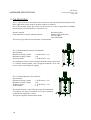
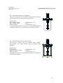
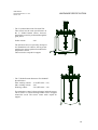
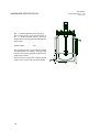
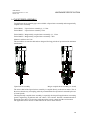
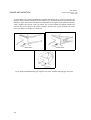
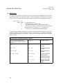
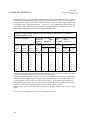
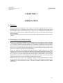
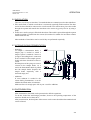
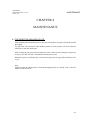
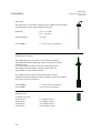
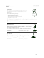
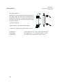
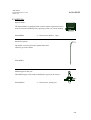
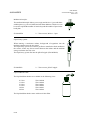
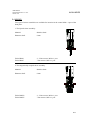
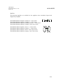
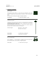
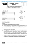
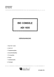
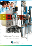
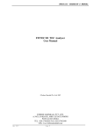
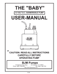
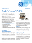
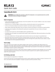
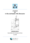
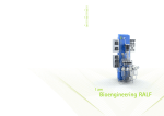
USER MANUAL
Autoclavable Bioreactor 2 - 7 l
October 1994
AUTOCLAVABLE
BIOREACTOR
2 - 7 LITER
USER MANUAL
V3UBCE0061
USER MANUAL
CONTENTS
Autoclavable Bioreactor 2 - 7 liter
October 1994
TABLE OF CONTENTS
Chapter
Description
Page
1
1.1
1.2
1.3
1.4
Hardware specification
General
The reactors
The head plates
The stirrer assemblies
1-1
1-1
1-2
1-7
1-9
2
2.1
2.2
2.3
Mixing and aeration
Mixing
Aeration
Literature
2-1
2-1
2-6
2-9
3
3.1
3.2
3.3
3.4
3.5
3.6
3.7
3.8
Operation
General
Preparing for sterilization
Sterilization
Installation
Preparing for operation
Inoculation
Actions during fermentation
Pasteurization
3-1
3-1
3-1
3-2
3-2
3-2
3-3
3-3
3-3
4
4.1
4.2
Maintenance
The reactor
The stirrer assembly
4-1
4-1
4-2
5
5.1
5.2
5.3
5.4
5.5
5.6
5.7
Auxiliaries
Sampling
Aeration
Addition
Mixing
Heat exchangers
Sensor holders
Blind stoppers
5-1
5-1
5-6
5-9
5-11
5-14
5-15
5-16
6
Drawings
6-1
USER MANUAL
HARDWARE SPECIFICATION
Autoclavable Bioreactor 2 - 7 liter
October 1994
CHAPTER 1
HARDWARE SPECIFICATION
1.1 GENERAL:
The stirred tank reactors (STR) are the most applied reactor types in biotechnology.
The Applikon 2 - 7 liter autoclavable bioreactors offer several advantages; its modular and
flexible design requires minimum bench space and is very practical in operation.
In combination with Applikons stirrer assemblies, motors, impellers and auxiliaries, you can
configure the reactor for a variety of applications, like:
- medium optimization,
- screening of strains,
- product optimization,
- scale up/down studies,
- reactor optimization,
- continuous cultures,
- perfusion systems, etc.
Danger:
Glass is a material that may be damaged easily (scratches
on the surface)! As a result, its strength is reduced.
Therefore do not apply a process pressure that exceeds 50
kPa (0.5 bar, 7 psig).
Reduce the pressure of the inlet gasses to this extend or
apply a pressure relief that is properly adjusted.
1-1
USER MANUAL
HARDWARE SPECIFICATION
Autoclavable Bioreactor 2 - 7 liter
October 1994
1.2 THE REACTORS:
The 2 - 7 liter bioreactors are ideals tool for researchers who start fermentation studies and for
those applications where small or medium volumes are required.
Due to the modular design, the reactors can be used for a variety of applications, including
microbial and yeast fermentations, cell cultures, etc.
Reactor material:
Other materials in contact with the medium:
borosilicate glass.
stainless steel (head plate),
silicone rubber,
viton and EPDM.
The reactor types and their specifications are listed below.
- The 2 l dished bottom bioreactor Z611020002:
Specifications:
Maximum working volume
: 2.2l (H/D ratio = 2.3)
Minimum working volume
: 0.5l
Working volume
: 1.7l (H/D ratio = 1.9)
For temperature control, a heat exchanger inside the reactor can be used
or a silicone heating blanket can be wrapped around the vessel. The
reactor comes with a tripod for support.
- The 2 l jacketed bioreactor Z61104CT04:
Specifications:
Maximum working volume
: 2.2l (H/D ratio = 2.3)
Minimum working volume
: 0.5l
Working volume
: 1.7l (H/D ratio = 1.9)
Jacket volume
: 1.3l
The jacketed reactor is especially developed for mammalian
cell cultures; the large heat transfer area ensures optimum
conditions for temperature control.
The tripod is supplied with extension shafts.
1-2
USER MANUAL
Autoclavable Bioreactor 2 - 7 liter
October 1994
HARDWARE SPECIFICATION
- The 3 l flat bottom bioreactor Z611000004:
This reactor is generally used for bacterial fermentations with micro
organisms that are not very sensitive to shear forces.
Specifications:
Max. working volume
: 3.2l (H/D ratio = 1.8)
Min. working volume
: 0.44l
Working volume
: 2.6l (H/D ratio = 1.5)
A heat exchanger, inside the vessel, or a silicone heating blanket,
wrapped around the vessel, can be used for temperature control.
- The 3 l dished bottom bioreactor Z61101C006:
This reactor is mostly used for culturing shear sensitive
cells/organisms. The dished bottom ensures optimum mixing
properties.
Specifications:
Total volume
: 3.2l (H/D ratio = 1.9)
Minimum working volume
: 0.47 ml
Working volume
: 2.7l (H/D ratio = 1.5)
Temperature control can be obtained in the same way as with the 3
l flat bottom bioreactor.
1-3
USER MANUAL
HARDWARE SPECIFICATION
- The 3 l jacketed bioreactor Z61103CT04:
This reactor has the same specifications as the 3 l
dished bottom reactor; however, temperature control is
performed through the glass jacket. In this way, the
temperature can be controlled more accurately; the
jacket can both be used for heating and cooling.
Internal jacket volume : 1.3l
- The 5 l dished bottom bioreactor Z611000005:
Specifications:
Max. working volume : 4.8l (H/D ratio = 1.6)
Min. working volume : 2l
Working volume
: 3.4l (H/D ratio = 1.1)
For temperature control, a heat exchanger inside the reactor
can be used or a silicone heating blanket can be wrapped
around the vessel. The reactor comes with a tripod for
support.
1-4
Autoclavable Bioreactor 2 - 7 liter
October 1994
USER MANUAL
HARDWARE SPECIFICATION
Autoclavable Bioreactor 2 - 7 liter
October 1994
- The 5 l jacketed bioreactor Z61104CT05:
This reactor has the same specifications as
the 5 l dished bottom reactor; however,
temperature control is performed through the
glass jacket.
Jacket volume
: 2.8l
The jacketed reactor is especially developed
for mammalian cell cultures; the large heat
transfer area ensures optimum conditions for
temperature control.
This reactor has a tripod for support.
- The 7 l dished bottom bioreactor Z611000007:
Specifications:
Max. working volume : 6.9l (H/D ratio = 2.2)
Min. working volume : 2.0l
Working volume
: 5.4l (H/D ratio = 1.8)
For temperature control, a heat exchanger inside the reactor
can be used or a silicone heating blanket can be wrapped
around the vessel. The reactor comes with a tripod for
support.
1-5
USER MANUAL
HARDWARE SPECIFICATION
- The 7 l jacketed bioreactor Z61103CT07:
This reactor has the same specifications as
the 7 l dished bottom reactor; however,
temperature control is performed through the
glass jacket.
Jacket volume
: 4.2l
The jacketed reactor is especially developed
for mammalian cell cultures; the large heat
transfer area ensures optimum conditions for
temperature control.
This reactor has a tripod for support (tripod
of the 5 liter reactor with extension shafts).
1-6
Autoclavable Bioreactor 2 - 7 liter
October 1994
USER MANUAL
HARDWARE SPECIFICATION
Autoclavable Bioreactor 2 - 7 liter
October 1994
1.3 THE HEAD PLATES:
The head plates are made of stainless steel 316. The port lay-outs are presented in the figures
below:
The 2 liter reactor:
The following ports are present:
- one central M 30 x 1 port (for the top stirrer),
- one G3/4" port (for dissolved oxygen sensor),
- five M 18 x 1.5 ports (for auxiliaries),
- three 6 mm ports (for baffles or other auxiliaries),
- six 10 mm ports (for auxiliaries).
The 3 liter reactor:
The following ports are present:
- one central M30 x 1 port (for the stirrer assembly),
- one G3/4" port (for dissolved oxygen sensor),
- five M18 x 1.5 ports (for auxiliaries like other sensors (pH, mV), etc.),
- two 12 mm ports (for auxiliaries like harvesting pipes, etc.),
- six 10 mm ports (for auxiliaries like air inlet pipes, etc.),
- three 6 mm ports (for baffles, etc.).
1-7
USER MANUAL
HARDWARE SPECIFICATION
Autoclavable Bioreactor 2 - 7 liter
October 1994
The 5 and 7 liter reactor:
The following ports are present:
- one central M 30 x 1 port (for the stirrer assembly),
- one G3/4" port (for the dissolved oxygen sensor),
- five M 18 x 1.5 ports (for auxiliaries like other sensors (pH, mV), etc.),
- two 12 mm ports (for auxiliaries like harvesting pipes, etc.),
- ten 10 mm ports (for auxiliaries like baffles, air inlet pipes, etc).
Caution:
It is strongly advised to ground the head plate in order to avoid disturbances on
electrode/sensor signals (static electricity); use one of the two 2 mm holes in the head
plate.
The other 2 mm hole can be used for level control connection.
1-8
USER MANUAL
HARDWARE SPECIFICATION
Autoclavable Bioreactor 2 - 7 liter
October 1994
1.4 THE STIRRER ASSEMBLY:
Two different stirrer assembly types are available: a lipseal stirrer assembly and a magnetically
coupled stirrer assembly .
Z81315R003:
Z81315R007:
Lipseal stirrer assembly 2, 3, 5 liter
Lipseal stirrer assembly 7 liter
Z81315MG03: Magnetically coupled stirrer assembly 2, 3, 5 liter
Z81315MG07: Magnetically coupled stirrer assembly 7 liter
Material: stainless steel 316.
The assemblies are autoclavable and are designed for long periods of operation with minimum
maintenance.
Lipseal stirrer assembly
Magn. coupled stirrer assembly (ex. shaft)
The stirrer shaft of the lipseal stirrer assembly is coupled directly to the stirrer motor. This is
the most common way of coupling, whereby contamination-free operation is ensured by the use
of viton lipseals.
The magnetically coupled stirrer assembly is especially developed for applications concerning
genetic engineering organisms and cell culture. This ensures absolute contamination-free
operation since there is no moving seal between the reactor content and the environment.
The applicable stirrer motors are described in the stirrer motor manual.
1-9
USER MANUAL
HARDWARE SPECIFICATION
1-10
Autoclavable Bioreactor 2 - 7 liter
October 1994
USER MANUAL
MIXING AND AERATION
Autoclavable Bioreactor 2 - 7 liter
October 1994
CHAPTER 2
MIXING AND AERATION
For an optimum performance of any biological system, it is necessary to keep the environment
of the micro-organisms at optimal conditions. Apart from temperature and medium
composition, the two most important factors that effect this environment are the degree of
mixing and aeration.
2.1 MIXING:
The aim of mixing is to obtain uniform conditions in the working volume of the bioreactor,
in order to obtain an optimal mass transfer, to avoid gradients of any of the medium
components, and to keep the microcarriers or cells in suspension. In a normally used stirred
tank reactor, mixing is accomplished by the impeller. The resulting flow pattern is a function
of the impeller configuration, agitation speed, the geometry of the system and gas inflow rate
employed.
One aspect of mixing is preventing the cells or microcarriers to settle. In order to achieve this,
the fluid velocity must at least be equal to the settling velocity of the particles (vsett), which can
be calculated according to Stokes' law (Cherry and Papoutsakis, 1986):
vsett = dp2(s - f)g/(18)
where: dp
s
f
g
= particle diameter (m),
= particle density (kg m-3),
= medium density (kg m-3),
= gravitational constant (m s-2)
= medium viscosity (N m s-1).
Stokes' law only holds for particles whose Reynolds numbers are smaller than 1 (which holds
for all normally used biological systems). As the biomass should be homogeneously
distributed throughout the reactor, not only must the particles be lifted from the bottom of the
vessel but they must also be transported through the whole volume of the reactor.
2-1
USER MANUAL
MIXING AND AERATION
Autoclavable Bioreactor 2 - 7 liter
October 1994
Generally, the minimum required stirring speed to achieve homogeneous suspension, Nhs, is
much greater than that to lift the particles from the bottom of the reactor. Buurman et al.
(1986) also derived a simple Froude relationship to define homogeneity in a stirred tank
reactor (STR), based on the assumption of fluctuating velocity being proportional to the
circulation velocity:
fNhs2Di2/(g(s - f)dp) = constant
where: Di
= diameter of the impeller (m)
which implies that:
Nhs 1/Di
The parameter used to describe the medium homogeneity aspect of mixing is the mixing time,
which is in fact also the characteristic time for mixing. The mixing time, tm, is often expressed
in the liquid circulation time, tc. In the case of a stirred tank tm equals 4 times tc (Voncken,
1966).
The liquid circulation time in STRs with a Rushton impeller can be calculated according to
(Oosterhuis, 1984):
tc = V/(0.75NDi3)
where: V
N
= working volume of the reactor (m3),
= rotation speed of the impeller (s-1),
If the geometry of the system has to be taken into account in ungassed STRs the following
correlation for the mixing time can be used:
tm = 1.2/N(D/Di)3(H/D)Np-1/3(Di/HI)2/3
where: D
H
Np
HI
= diameter of the reactor (m),
= liquid height in the reactor (m),
= impeller power number (-),
= height of impeller blade (m).
The impeller power number is a constant for a given system and related to the power input by
the stirrer (Ps) in the following way:
Ps = NpfN3Di5
The mixing time in a gassed STR is, as a rule of thumb, twice as high as in an ungassed STR.
The resulting mixing time in ADI's autoclavable bioreactors for mammalian cell and bacterial
culture under average operating conditions (ungassed) is given in the following table.
2-2
USER MANUAL
MIXING AND AERATION
Autoclavable Bioreactor 2 - 7 liter
October 1994
Applikon Dependable Instruments Autoclavable Bioreactors: Mixing times
Reactor configuration
Mammalian cell culture
N=100rpm, Marine imp.
Bacterial culture
N=1000rpm, Rushton imp.
Reactor
Impeller
Reactor
Liquid
Impeller
Impeller
Mixing
Impeller
Impeller
Mixing
volume
diameter
diameter
height
power
height
time
power
height
time
V (l)
Di (mm)
Dr (mm)
H (mm)
no Np
HI (mm)
tm (sec)
no Np
HI (mm)
tm (sec)
1
45
96
150
3
28
1.3
6
11
0.2
2
45
115
125
3
28
1.6
2
45
105
175
12
11
0.2
3
45
130
200
3
28
3.2
12
11
0.4
5
60
170
200
3
37
2.8
12
15
0.3
7
60
170
300
6
37
3.4
18
15
0.4
15
74
222
365
6
45
4.3
18
15
0.5
20
74
222
550
9
45
5.7
18
19
0.8
Measurements of the mixing time in a two and three liter reactor have shown to comply well
with these correlations (Kakes and Oosterhuis, 1990). It is obvious from this table that the
mixing times are very small in relation to the characteristic times that are to be expected for
the metabolism (e.g. oxygen uptake rate, substrate consumption rate) of the micro-organisms.
Therefore the medium can be looked upon as being ideally mixed at all times during
fermentation.
2-3
USER MANUAL
MIXING AND AERATION
Autoclavable Bioreactor 2 - 7 liter
October 1994
As the bubbles are coalescing behind the impeller and broken up by vortices created by the
impeller, the gas will be homogenised in a similar way as the medium and its components. The
influence of gas feed on this mechanism is illustrated in the figure below (Warmoeskerken,
1986). Despite this mixing of the gas phase, the cavities behind the impeller blades will
decrease the power input to the reactor and thus decrease the oxygen transfer rate to the
reactor medium (see chapter 2.2: aeration).
Cavity shape behind Rushton type impellers for small, medium and high gas feed rates.
2-4
USER MANUAL
Autoclavable Bioreactor 2 - 7 liter
October 1994
MIXING AND AERATION
The operating range of the impeller speed is limited due to the potential damaging effect of
the rotating impeller on the micro-organisms. Therefore, it may be impossible to satisfy the
criteria for homogeneity. Furthermore, a Rushton type of impeller will only create a
homogeneous distribution of bubbles throughout the reactor at relatively high rotation speed
(>500 rpm, see figure below, Nienow et al., 1977). Differences in sensitivity to damaging by
the impeller and oxygen requirements between bacteria, fungi and mammalian cells have led
to the development of various types of impellers. To improve the axially mixing
characteristics of the Rushton impeller, impellers with angled blades have been developed. To
reduce the damaging effect of the impeller, the (angled) blades are curved in order to create
a marine type of impeller for application in mammalian cell or fungi cultures. This impeller
also has a good axially pumping capacity which ensures mixing of the complete reactor
medium and improves refreshment of the topmost layer of liquid to achieve higher oxygen
transfer rates without sparging (see chapter 2.2: aeration).
Gas circulation patterns in aerated stirred vessels at increasing stirring speed (constant gas
feed).
2-5
USER MANUAL
MIXING AND AERATION
Autoclavable Bioreactor 2 - 7 liter
October 1994
2.2 AERATION:
Gas-liquid mass transfer in cell culture systems is governed by the solubility of the gas in the
liquid medium (Bliem and Katinger, 1988), its molecular diffusivity and the driving force of
the gas (which vary with temperature and pressure), and may be described by the expression:
OTR = kla(O* - Ol)
where: OTR
kl
a
O*
Ol
= oxygen transfer rate,
= liquid phase mass transfer coeff.,
= gas-liquid interfacial area per unit liquid volume,
= liquid phase oxygen concentration in equilibrium with the
bulk gas phase (at 1 atm and 37C: 0.18 mmol O2/l).
= actual oxygen concentration of the liquid phase.
The term kla represents the volumetric overall mass transfer coefficient and is one of the most
common parameters used to describe the efficiency of an aeration system. Bliem and Katinger
(1988) compared the typical efficiency of some forms of aeration which are given in the
following table.
Efficiencies of different aeration systems
Typical oxygen transfer rates
under culture conditions, using air
(cm s-1)
kl a (s-1)
Aeration system
10-6
10-6
static liquid surface
aeration.
10-6 - 10-3
10-6 - 10-3
stirred liquid surface
aeration.
10-5 - 8 * 10-5
10-4 - 10-2
silastic membrane
aeration.
5 * 10-5 - 3 * 10-4
10-4 - 3 * 10-4
dynamic wire mesh
(with agitation).
< 7 * 10-3
sparged and stirred
liquid for cell culture.
10-2 - 7 * 10-1
sparged and stirred
liquid for microbial
culture.
2-6
USER MANUAL
MIXING AND AERATION
Autoclavable Bioreactor 2 - 7 liter
October 1994
The kla-values are strongly influenced by the medium composition. For example, the addition
of silicone antifoam can cause the kla to decrease drastically whereas the addition of salts to
the medium will increase the kla (Lavery and Nienow, 1987; Bliem and Katinger, 1988).
For a mammalian cell culture to a density of 5109 cells/l (a typical batch culture), the oxygen
requirement is in the range of 5-50 ml O2/lh (at 37C and atmospheric pressure). Therefore,
the required kla for a typical batch culture operation is likely to be 0.5-510-4 s-1. Static liquid
surface aeration is insufficient even for these low requirements (see table on previous page).
For high density cultivation, as reached in long-term perfusion systems, the required kla may
increase to as much as 0.1-110-2 s-1; this oxygen requirement can only be supplied by
sparging.
Sparging is the most efficient way to obtain high kla values. Most experimental data for kla
values can be estimated by the correlations of Van 't Riet (1979) and Henzler (1982) (adapted
for temperature difference):
for coalescing media:
kla = (1.022(T-20))0.026(Pg/V)0.4vs0.5
for non-coalescing media:
kla = (1.022(T-20))0.016(Pg/V)0.7vs0.2
where: T
Pg
V
vs
= temperature (oC),
= the gassed power input by impeller (N m s-1),
= volume (m3),
= superficial gas velocity (m s-1).
At very low aeration rates Pg will be equal to the ungassed power input Ps (Lavery and
Nienow, 1987) but at higher aeration rates the gassed power input has to be calculated
according to:
Pg 0.5Ps = 0.5NpfN3Di5
2-7
USER MANUAL
MIXING AND AERATION
Autoclavable Bioreactor 2 - 7 liter
October 1994
The theoretical kla values from these correlation for ADI's autoclavable reactors are given in
the table below. Measurements of kla values on a two and three liter scale have shown that the
oxygen transfer capacity that can be reached in practice is upto 10 times higher (Kakes and
Oosterhuis, 1990). Sparging, however, is known to cause inadmissible shear stress for
mammalian cells, will increase the problem of foam formation in bacterial as well as
mammalian cultures and is, therefore, limited in its applications.
Applikon Dependable Instruments Autoclavable Bioreactors: Theoretical
oxygen transfer rates.
Reactor configuration
Mammalian cell culture,
N=100 rpm,
Marine
impellers, Aeration =
0.05 vvm.
Bacterial culture, N=1000
rpm,
Rushton
impellers, Aeration = 1
vvm.
Reactor
Impeller
Reactor
Impeller
Oxygen transfer
Impeller
Oxygen transfer
volume
diameter
diameter
power
coalesc.
power
coalesc.
V (l)
Di (mm)
Dr (mm)
-1
non coal
-1
-1
non coal
no Np
kla (h )
kla (h )
no Np
kla (h )
kla (h-1)
6
7
33
12
8
37
1
45
96
3
1
18
2
45
115
3
1
12
2
45
105
3
45
130
3
1
9
12
7
27
5
60
170
3
2
18
12
10
52
7
60
170
6
2
24
18
12
59
15
74
222
6
3
31
18
16
75
20
74
222
9
4
36
18
16
65
Since the required kla value and admitted aeration flow vary widely from system to system,
various ways are used to introduce a gas flow into the system.
For mammalian cell cultures mostly an (oxygen enriched) air overlay is used in combination
with an axially pumping impeller. In order to get a large surface area and thus improve the
oxygen transfer, reactors with a low H/D value (usually 1) are used for this application.
Fermentations that require both a low stirrer speed and gas flow need a sintered steel sparger
in order to create small bubbles and thus a large area for oxygen transfer.
High gas flow rates can be reached with open pipes, or pipes with several relatively large
holes.
All options are available for every ADI autoclavable bioreactor.
2-8
USER MANUAL
Autoclavable Bioreactor 2 - 7 liter
October 1994
MIXING AND AERATION
2.3 LITERATURE:
Bliem, R. and Katinger, H. (1988) Tibtech, 6, 190-195 and 224-230.
Buurman, C., Resoort, G. and Plaschkes, A. (1986) Chem. Eng. Sci., 41, 2865.
Cherry, R.S. and Papoutsakis, E.T. (1986) Bioproc. Eng., 1, 29-41.
Henzler, H.J. (1982) Chem. Ing. Techn., 54, 461.
Kakes, E. and Oosterhuis, N.M.G. (1990) A poster presentation on the Dutch Congress on
Biotechnology.
Lavery, M. and Nienow, A.W. (1987) Biotechnol. Bioeng., 30, 368-373.
Nienow, A.W., Wisdom, D.J. and Middleton, J.C. (1977) 2nd Eur. Conf. on Mixing,
30-3, Cambridge, England, Paper F1.
Oosterhuis, N.M.G. (1984) Ph.D. Thesis, T.U. Delft, The Netherlands.
Van 't Riet, K. (1979) Ind. Eng. Chem. Proc. Des. Dev., 18, 367-375.
Voncken, R.M. (1966) Ph.D. Thesis, T.U.Delft, The Netherlands.
Warmoeskerken, M.M.C.G. (1986) Ph.D. Thesis, T.U. Delft, The Netherlands.
2-9
USER MANUAL
MIXING AND AERATION
2-10
Autoclavable Bioreactor 2 - 7 liter
October 1994
USER MANUAL
OPERATION
Autoclavable Bioreactor 2 - 7 liter
October 1994
CHAPTER 3
OPERATION
3.1 GENERAL:
When unpacking the equipment, verify if there is any transport damage and if the reactor is
complete (the way you ordered it). Clean all parts with 70% ethanol to remove dust or dirt
from shipping. When assembling the reactor, make sure not to damage the threaded ports;
always screw in the auxiliaries straight and by hand. Do not use tools to tighten the auxiliaries
in the head plate.
Make sure that an O-ring is present between the auxiliary and the head plate in order to ensure
sterility.
3.2 PREPARING FOR STERILIZATION:
Fill the vessel with culture medium, do not exceed the total volume that is specified in chapter
1 (hardware specification). Be sure to leave enough volume for additions after sterilization
(e.g. inoculum, separately sterilized nutrients, etc.). Fasten the six mill nuts crosswise by hand.
Verify the functioning of the electrodes (refill electrolyte of the pH electrode). Insert the Level
probe as far as possible into the vessel and fasten it (after sterilization, the position of this
probe can be adjusted, upward to the desired height).
Verify the mounting of all nipples and other auxiliaries. Make connections for liquid
additions, air in and air out with silicone tubing or other suitable sterilizable material. Use
appropriate filters for air in and air out. To avoid wetting of the inlet filter during sterilization,
use a clamp to close the tubing between the head plate and the filter. Close all other
connections (except the air out) air-tight with a hose and a hose clamp. Close all open tubing
ends with cotton and cover the ends with sterilizable foil or paper.
Make sure that the vessel is not completely closed, since pressure differences during
sterilization may damage the reactor or the probes. Use the air outlet filter to maintain pressure
equilibrium in- and outside the reactor. The heat exchanger should be empty during
sterilization.
3-1
USER MANUAL
OPERATION
Autoclavable Bioreactor 2 - 7 liter
October 1994
3.3 STERILIZATION:
The bioreactor with all accessories (except the stirrer motor) can be placed in an autoclave.
The space, needed in the autoclave can be derived from the drawings that are enclosed in the
English copy of this manual.
The autoclave should stay at 121oC for at least 20 minutes in order to kill all organisms and
thermo-resistant spores. After sterilization, let the autoclave cool down without opening it,
until the temperature is below 90oC. When the temperature in the autoclave has dropped below
90oC, it can be opened to allow it to cool down further. This cooling procedure should be
performed to avoid low pressure in any part of the reactor system. Low pressure in tubing
might result in contamination when the tube is connected to a peripheral device. Low pressure
in a pH-electrode may result in sudden boiling of the electrolyte.
Note:
In case of a jacketed reactor, the sterilization interval might need to be increased, since the
empty jacket has a poor heat transfer capacity.
If the medium cannot stand a longer interval, you can fill the jacket with water to improve the
heat transfer (connect and close the lower tube fitting, do not close the upper one).
3.4 INSTALLATION:
Put the reactor as near as possible to the control equipment (the Bio Processor or Bio
Controller) and connect all electrodes to this equipment. Connect the heat exchanger to the
thermo circulator; hook up the air inlet pipe to the flow console and, if present, connect
cooling water to the condenser. Connect all sterile fluids (acid, base, etc.) that have to be
added to the medium, aseptically to the inlet pipes.
To improve heat transfer between the thermometer pocket and the Pt100-sensor, fill the
thermometer pocket with water or silicone oil. This will decrease the dead time of the sensor
and will make your temperature control more accurate.
When operating at higher temperature, silicone oil has the advantage of a lower vapour
pressure (less evaporation).
3.5 PREPARING FOR OPERATION:
After connecting all cables and tubing, adjust the setpoints of the controllers to the desired
value (temperature, pH, DO2, etc.).
Switch on the thermo circulator, stirrer motor, acid and/or base pumps and gas flow.
When temperature, pH etc. have reached their setpoint (and are stabilized), the bioreactor is
ready for inoculation.
3-2
USER MANUAL
Autoclavable Bioreactor 2 - 7 liter
October 1994
OPERATION
3.6 INOCULATION:
There are several ways to inoculate. Two methods that are commonly used are described here:
1. Fill a sterile flask, to which a sterile hose is connected, aseptically with inoculum. The other
end of the hose should be connected to a sterile needle. Turn off aeration, pierce the needle
through the septum and transfer the inoculum to the reactor by gravity feed or by using a
pump.
2. In this case a sterile syringe is filled with inoculum. The needle is pierced through the septum
and the inoculum is pushed into the reactor (this method is suitable for inoculum volumes
smaller than 100 ml).
Other methods of inoculation can be used if they are performed aseptically.
3.7 ACTIONS DURING FERMENTATION:
- Sampling:
To sample a fermentation broth, a
sample pipe is needed to which a
sample system is attached. Connect a
syringe to the tubing that is connected
to the "out barb" of the sample system.
In this tube there should be a filter or
cotton.
Pull the piston of the syringe to create a
vacuum in the sample bottle. As a
result, the fermentation broth is pulled
into the sample bottle. Replace the
sample bottle aseptically with a
sterilized empty one.
- Additions:
If extra substrate is needed in the
culture during fermentation, it can be
added as described under "inoculation".
Make sure there is enough space left in your vessel for additions.
3.8 PASTEURISATION:
After fermentation, the broth can be pasteurized to kill the organisms.
To do this, follow the sterilization procedure, however the operating temperature of the
autoclave should now be about 80oC.
After pasteurization, the head plate of the reactor can be removed and the fermentation broth
can be collected.
3-3
USER MANUAL
OPERATION
3-4
Autoclavable Bioreactor 2 - 7 liter
October 1994
USER MANUAL
MAINTENANCE
Autoclavable Bioreactor 2 - 7 liter
October 1994
CHAPTER 4
MAINTENANCE
4.1 THE REACTOR AND HEAD PLATE:
After finishing the fermentation process, the glass and stainless steel parts should be cleaned
thoroughly.
Use hot water, 70% ethanol or other suitable cleaners to clean all parts. Never use abrasive
materials to clean the metal parts.
After cleaning, dry the parts and reassemble the reactor. Take care not to damage or forget any
O-rings, since this can cause contamination during the next run.
When the reactor is used frequently, it is advised to replace the O-rings of the auxiliaries twice
a year.
Note:
Make sure that the pH-electrode is cleaned thoroughly before it is stored; refer to the user
manual of this electrode.
4-1
USER MANUAL
MAINTENANCE
Autoclavable Bioreactor 2 - 7 liter
October 1994
4.2 THE STIRRER ASSEMBLY:
The stirrer assembly should be disassembled, cleaned and lubricated twice a year.
Disassembling instructions are listed below:
4.2.1 LIPSEAL STIRRER ASSEMBLY:
- Remove the head plate from the
reactor and remove the impellers from
the stirrer shaft. Screw the stirrer
assembly out of the head plate.
- Remove the coupling ring (A) at the
top of the assembly by unscrewing the
four slotted cheese head screws.
- Screw out the pillars (B) on which the
coupling ring was mounted and
remove the "spring pin" (C) and the
upper lipseal (D). Take off the upper
cover (E) of the stirrer assembly.
- Remove the lower cover (H) by
loosening the three small screws and
removing the lipseal.
- Remove the circlip (G) from the shaft
(on top of the ball bearing (F)).
- Turn the stirrer assembly upside
down, and gently push the shaft out of
the ball bearing house. This is most
easily achieved by placing the top of
the stirrer shaft on the table (upside
down) and pressing the housing down.
- Clean all parts and lubricate the ball
bearing again with special grease (art.
no. V3LA120031). Replace any Oring or lipseal if necessary and
reassemble the stirrer assembly
carefully.
4-2
USER MANUAL
Autoclavable Bioreactor 2 - 7 liter
October 1994
MAINTENANCE
4.2.2 MAGNETICALLY COUPLED STIRRER ASSEMBLY:
- Remove the head plate from the
reactor and put it upside down on the
motor coupling ring of the stirrer
assembly.
- Turn the dismantling screw (A) as far
as possible into the housing. Loosen
the lower part of the stirrer assembly
by turning the rotor (B) counter
clockwise. Pull off the lower part; be
aware of the magnetic field.
- Remove the motor coupling part from
the head plate by turning it counter
clockwise.
- Dismantle the motor coupling part by
unscrewing the 4 slotted cheese head
screws and unscrew the pillars (C).
Remove the spring pin (D) from the
shaft and remove the upper lipseal
(E). Remove the top-plate (F).
- Pull the stirrer shaft and the innermagnets out of the housing.
- Clean all parts with tissue paper,
lubricate the ball bearings (G) with
the special grease (art. no.
V3LA120031).
- Remove the stirrer shaft from the
rotor section; clean and lubricate the
surface of the ball bearing (G).
- Replace any O-ring or lipseal if necessary and reassemble the stirrer assembly carefully.
4-3
USER MANUAL
MAINTENANCE
4-4
Autoclavable Bioreactor 2 - 7 liter
October 1994
USER MANUAL
AUXILIARIES
Autoclavable Bioreactor 2 - 7 liter
October 1994
CHAPTER 5
AUXILIARIES
In this chapter, the head-plate-auxiliaries for the 2 - 7 liter bio-reactors are listed.
5.1 SAMPLING:
Assembly holder 6 mm tube for M18 x 1.5 port:
This device fits into a M18 x 1.5 port and can be used to hold any 6
mm (O.D.) tube. The insertion length of this tube can be varied;
additions to or sampling from the culture fluid can take place at any
level inside the reactor.
Z811302015
2 - 7 liter reactor, M18 x 1.5 port
Assembly holder 6 mm tube for 10 mm port:
This device can be inserted into a 10 mm port and can be used to hold
any 6 mm (O.D.) tube. The insertion length of this tube can be varied;
additions to or sampling from the culture fluid can take place at any
level inside the reactor.
Z81320AH00
2 - 7 liter reactor, 10 mm port
5-1
USER MANUAL
AUXILIARIES
Autoclavable Bioreactor 2 - 7 liter
October 1994
Sample pipe (fixed length):
This assembly is used to sample the culture fluid.
Tube diameter (O.D.): 6 mm (to fit in a 10 mm port)
9.5 mm (to fit in a 12 mm port)
Insertion length:
213 mm (for 2, 3 and 5 l reactors)
325 mm (for 7 l reactor)
Z81319MB03
Z81319MB05
Z81319MB07
Z81319MB08
2 - 5 liter reactor, 10 mm port
2 - 5 liter reactor, 12 mm port
7 liter reactor, 10 mm port
7 liter reactor, 12 mm port
Sample pipe (height adjustable):
The height adjustable sample pipe assembly consists of:
- an assembly holder for 6 mm tubes and
- a O.D. 6 mm sample tube.
Tube diameter (I.D.): 4 mm.
Maximum insertion length:
232 mm (2 - 5 liter reactor)
320 mm (7 liter reactor)
With this device, the culture fluid can be sampled at any desired level.
Z81319MB04
Z81319MB06
5-2
2 - 5 liter reactor, 10 mm port
7 liter reactor, 10 mm port
USER MANUAL
AUXILIARIES
Autoclavable Bioreactor 2 - 7 liter
October 1994
Chemostat tube:
The chemostat tube is used in continuous fermentation.
This device is designed to achieve a constant level
in the reactor.
Liquid is taken out of the reactor through the height
adjustable inner tube.
This inner tube is shielded from the reactor by an outer
tube to avoid the influence of foam and surface irregularities
on the liquid level.
Diameter outer tube:
O.D. = 8 mm
I.D. = 6 mm
Diameter inner tube:
O.D. = 3.18 mm
I.D. = 1.4 mm
Insertion length:
(outer tube)
156 mm (1 - 5 liter reactor)
306 mm (7 liter reactor)
Z81206CH03
Z81206CH07
2 - 5 liter reactor, M18 x 1.5 port
7 liter reactor, M18 x 1.5 port
Sample pipe (I.D. = 1.56 mm):
This sample pipe is designed for the sampling of small volumes.
The internal diameter of the pipe guaranties a minimum
dead volume. The sample pipe fits into a 6 mm (baffle) port or into a 10 mm
port, depending on type number.
Insertion length:
180 mm
Z81319MB13
Z81319MB15
2 and 3 liter reactor, 6 mm port
2 - 7 liter reactor, 10 mm port
5-3
USER MANUAL
AUXILIARIES
Autoclavable Bioreactor 2 - 7 liter
October 1994
Drain tube:
The drain tube is used to take relatively large samples from the culture
and to drain bio-reactor after finishing the process.
Diameter:
O.D. = 6.35 mm
I.D. = 4.53 mm
Insertion length:
217 mm
Z81319MB14
2 - 5 liter reactor, 10 mm port
Sample pipe for screens:
The sample pipe for screens has a very small dead volume.
The height adjustable sample pipe can be used with or without
a sample screen.
If it is used without sample screen, the small dead volume
of the pipe guarantees samples from the culture that are
representative for the reactor contents.
If a sample screen is used at the end of this pipe, cell free
samples can be drawn from the culture. Sample screens are available
in several pore sizes (see below).
Z81319MB09
Z81319MB11
2 - 5 liter reactor, 10 mm port
7 liter reactor, 10 mm port
Sample screen:
Available pore sizes:
Z811303010
Z811303011
Z811303012
Z811303013
5-4
13 µ sample screen
25 µ sample screen
76 µ sample screen
105 µ sample screen
USER MANUAL
AUXILIARIES
Autoclavable Bioreactor 2 - 7 liter
October 1994
Sample pipe I.D. 10 mm:
This sample pipe is designed for sampling cultures
with flocculating organisms (in this case a sample
pipe with a small diameter will ruin the flocks and
the pipe will be clogged).
The shear forces inside this sample pipe are nearly negligible.
The sample pipe can be fitted in a 12 mm I.D. pH/mV nipple.
Z81319MB22
Z81319MB23
2 - 5 liter reactor, pH/mV nipple
7 liter reactor, pH/mV nipple
Sample system:
The sample system with a 60 (or 30) ml glass bottle can be mounted
onto the head plate of the bio-reactor.
This system, completed with a syringe and connected
to the sample pipe (tubing), provides your bio-reactor with an easily
operated sampling device.
Z81207SS02
2 - 7 liter reactor
5-5
USER MANUAL
AUXILIARIES
Autoclavable Bioreactor 2 - 7 liter
October 1994
5.2 AERATION:
Air-inlet pipe:
To meet the oxygen demand of a culture, a sterile gas stream can be
sparged through the culture, using an
air-inlet pipe.
This pipe can be applied when high gas flow rates are
required, since this pipe causes hardly any pressure drop.
The holes in this pipe are located at the bottom to make sure that
medium will be driven out by the gas stream.
Insertion length:
236 mm (2 - 5 liter reactor)
330 mm (7 liter reactor)
Z81318L002
Z81318L003
Z81318L005
Z81318L007
2 liter reactor, 10 mm port
3 liter reactor, 10 mm port
5 liter reactor, 10 mm port
7 liter reactor, 10 mm port
Air-inlet pipe with porous sparger:
In cell culture fermentations, high gas flow rates (causing shear forces)
might damage the cells.
To be able to meet the oxygen demand of the cells at lower gas flow, the
exchange-surface must be increased.
This can be achieved by using this sparge pipe.
The sintered metal tip produces tiny air bubbles for optimum gas
distribution.
Insertion length:
238 mm (2 - 5 liter reactor)
330 mm (7 liter reactor)
Z81318L004
Z811303005
Z81318L006
Z81318L008
2 liter reactor, 10 mm port
3 liter reactor, 10 mm port
5 liter reactor, 10 mm port
7 liter reactor, 10 mm port
Z811303008
Porous sparger for air-inlet pipe
5-6
USER MANUAL
AUXILIARIES
Autoclavable Bioreactor 2 - 7 liter
October 1994
Tuning valve:
The tuning valve can be installed on top of the stainless steel
air-outlet condenser in order to create a small over-pressure
in the reactor.
This has the following advantages:
- risk of contamination is reduced,
- oxygen transfer to the medium is increased,
- sampling the culture is eased.
For safety reasons it is strongly advised to use this tuning valve in combination with the
pressure relief valve (listed below).
Z811302020
1 - 7 liter reactor
Pressure relief valve:
When over-pressure is applied in the (glass) Applikon 1 - 7 liter bio-reactors,
it is advised to install this relief valve.
The pressure at which the relief valve will open can be adjusted manually.
Z811302050
1 - 7 liter reactor, M18 x 1.5 port
Air-outlet pipe:
The air-outlet pipe can be used for either gas outlet or gas overlay.
The latter use is for head space aeration (separate from or in
combination with sparging gas through the culture).
Z81308LU02
2 - 7 liter reactor, 10 mm port
5-7
USER MANUAL
AUXILIARIES
Autoclavable Bioreactor 2 - 7 liter
October 1994
Air-outlet condenser:
Working at elevated temperature and using aeration of
the culture might cause too much evaporation during
fermentation (increase of nutrient concentration and
decrease in volume); this can be prevented by using an
air-outlet condenser.
Available condensers:
- glass condenser, fits into the pH/mV nipple.
- stainl. steel condenser, fits into the M18 x 1.5 port
Z81309L003
Z81309L002
Z81309L007
5-8
glass condenser for 2 - 5 liter reactor, pH/mV nipple
SS condenser for 2 - 5 liter reactor, M18 x 1.5 port
SS condenser for 7 liter reactor, M18 x 1.5 port
USER MANUAL
AUXILIARIES
Autoclavable Bioreactor 2 - 7 liter
October 1994
5.3 ADDITION:
Septum holder:
The septum holder is equipped with a silicone rubber septum and can be
used as a universal addition port by piercing it with one or more needles.
Z81302PD02
2 - 7 liter reactor, M18 x 1.5 port
Needle for septum:
The needle is used to pierce the septum and to add
a fluid or gas to the culture.
Z81309IN02
Addition pipe 10 mm port:
This addition pipe can be used to add fluids or gasses to the reactor.
Z81324MT02
2 - 7 liter reactor, 10 mm port
5-9
USER MANUAL
AUXILIARIES
Autoclavable Bioreactor 2 - 7 liter
October 1994
Medium inlet triple:
The medium inlet triple allows you to equip one M18 x 1.5 port with three
addition ports (e.g. for acid, alkali and anti-foam addition). This device can
be used to expand the number of entries beyond the number of ports in the
head plate.
Z81324MT03
2 - 7 liter reactor, M18 x 1.5 port
Liquid entry system:
When running a continuous culture, backgrowth of organisms into the
medium container must be prevented.
The liquid entry system uses a sterile gas flow to transfer the fresh medium to
the reactor; in this way, direct contact between the culture and the medium
storage container does not exist.
The liquid entry system fits into the pH/mV nipple (Z81300N002).
Z81309IN03
2 - 7 liter reactor, pH/mV nipple
Liquid addition bottle:
The liquid addition bottles are available in the following sizes:
0.5 liter
1.0 liter
2.0 liter
5.0 liter
10 liter
20 liter
Z811302009
Z811302010
Z811302011
Z811302012
Z811302013
Z811302014
The liquid addition bottle comes with an air-inlet filter.
5-10
USER MANUAL
AUXILIARIES
Autoclavable Bioreactor 2 - 7 liter
October 1994
5.4 MIXING:
Two types of stirrer assemblies are available for insertion in the central M30 x 1 port of the
head plate:
1. The lipseal stirrer assembly:
Material:
Stainless Steel
Diameter shaft:
8 mm
Z81315R003
Z81315R007
2 - 5 liter reactor, M30 x 1 port
7 liter reactor, M30 x 1 port
2. The magnetically coupled stirrer assembly:
Material:
Stainless Steel
Diameter shaft:
8 mm
Z81315MG03
Z81315MG07
2 - 5 liter reactor, M30 x 1 port
7 liter reactor, M30 x 1 port
5-11
USER MANUAL
AUXILIARIES
Autoclavable Bioreactor 2 - 7 liter
October 1994
Baffle assembly:
Baffles are used to increase the mixing efficiency (without baffles, the medium
flow can become laminar, causing poor mixing efficiency and mass transfer).
The baffles are mounted near the reactor wall for optimum mixing performance.
The baffle assembly consists of one baffle and mounting material.
Normally three baffles are used to create maximum mixing efficiency.
Insertion length:
220 mm (for 2 and 3 liter reactor)
223 mm (for 5 liter reactor)
317 mm (for 7 liter reactor)
Z81326KS03
Z81326KS05
Z81326KS07
2 and 3 liter reactor, 6 mm port
5 liter reactor, 10 mm port
7 liter reactor, 10 mm port
Draught tube:
The draught tube is used to obtain maximum mixing
efficiency and optimum oxygen mass transfer by
enforcing an axial flow pattern in the reactor.
The draught tube must be used in combination with a
marine impeller (the vortex type for foam killing, the
scoping type in case a vortex or gas bubbles in the culture
liquid are not allowed).
Insertion length:
Tube length:
220 mm (3 liter reactor)
120 mm
Draught tubes for other reactors: on request.
Z81334DT03
5-12
3 liter reactor, 3 x 6 mm port
USER MANUAL
Autoclavable Bioreactor 2 - 7 liter
October 1994
AUXILIARIES
Impellers:
The following impellers are available for the Applikon stirrer assemblies (lipseal and
magnetically coupled):
Z81312RS02 Rushton impeller, 4 bladed, 2 - 3 liter reactor
Z81313R602 Rushton impeller, 6 bladed, 2 - 3 liter reactor
Z81313R645 Rushton impeller, 6 bladed (vortex), 2 - 3 liter reactor
Z81313R607 Rushton impeller, 6 bladed, 5 and 7 liter reactor
Z81314RC02 Marine impeller (vortex), 2 - 3 liter reactor
Z81314RC03 Marine impeller (scoping), 2 - 3 liter reactor
Z81314RC07 Marine impeller (vortex), 5 and 7 liter reactor
Z81314RC08 Marine impeller (scoping), 5 and 7 liter reactor
5-13
USER MANUAL
AUXILIARIES
Autoclavable Bioreactor 2 - 7 liter
October 1994
5.5 HEAT EXCHANGERS:
Two different types of heat exchangers are available.
1: fitting into a M18 x 1.5 port. This heat exchanger can be used in the 2 - 5 liter
reactors.
Insertion length:
226 mm
Z81317KV03
2 - 5 liter reactor, M18 x 1.5 port
2: fitting two 10 mm ports. This type of heat exchanger is
available for the 5 and 7 liter reactor.
Insertion length:
210 mm (5 liter reactor)
315 mm (7 liter reactor)
Z81317HE05
Z81317HE07
5 liter reactor, two 10 mm ports
7 liter reactor, two 10 mm ports
5-14
USER MANUAL
AUXILIARIES
Autoclavable Bioreactor 2 - 7 liter
October 1994
5.6 SENSOR HOLDERS:
pH/mV nipple:
This nipple fits into a M18 x 1.5 port and can accommodate a pH or mV
electrode, a liquid entry system, the glass condenser or other 12 mm (O.D.)
tubes.
All items that are hold by this nipple are height-adjustable.
Z81300N002
2 - 7 liter reactor, M18 x 1.5 port
Thermometer pocket:
Temperature measurement (and control) is very important in bio-technology.
The thermometer pocket allows you to insert a temperature probe (Pt100 or
mercury thermometer) in the reactor.
Fill the thermometer pocket with water or silicone oil in order to improve
thermal contact between the culture and the probe.
Insertion length:
200 mm (2 - 5 liter reactor)
300 mm (7 liter reactor)
Z81323TP03
Z81323TP07
2 - 5 liter reactor, 10 mm port
7 liter reactor, 10 mm port
DO2 electrode holder:
Every Applikon 2 - 7 liter head plate is equipped with a G3/4" port for the
DO2 electrode holder. The electrode is height-adjustable.
Z811303001
2 - 7 liter reactor, G3/4" port
5-15
USER MANUAL
AUXILIARIES
Autoclavable Bioreactor 2 - 7 liter
October 1994
Nipple ID = 12 mm for G3/4" port:
This nipple can be used to fit a pH or mV electrode or
any other device with an OD of 12 mm (height adjustable).
Z81300N005
1 - 7 liter reactor, G3/4" port
Available sensors:
Z71201AP10
Z71201AP20
Z71201AG10
Z71201AG20
Z71202AP10
Z71202AP20
Z71203MV02
Z71204T002
Z71205AF03
Z711203001
Sensor pH, L = 235 mm for 2 - 5 liter reactor
Sensor pH, L = 385 mm for 7 liter reactor
Sensor pH gel, L = 235 mm for 2 - 5 liter reactor
Sensor pH gel, L = 385 mm for 7 liter reactor
Sensor DO2, L = 215 mm for 2 - 5 liter reactor
Sensor DO2, L = 215 mm for 7 liter reactor
Sensor redox, L = 320 mm
Sensor temperature, L = 200 mm
Sensor foam for 2 - 7 liter reactor
Level detector for 2 - 7 liter reactor
5.7 BLIND STOPPERS:
Blind stopper 6, 10 and 12 mm ports:
These blind stoppers can be used to blind unused ports in the head plate;
the assemblies are fitted into the head plate from the inside of the reactor,
leaving only a flat surface in the reactor.
Z81321BP03
Z81322BP03
Z81322BP08
2 and 3 liter reactor, 6 mm port
2 - 7 liter reactor, 10 mm port
2 - 7 liter reactor, 12 mm port
Blind stopper threaded ports:
The following blind stoppers are available for the threaded ports:
Z81301BD04
Z81301BD03
Z81301BD02
5-16
2 - 7 liter reactor, G3/4" port
2 - 7 liter reactor, M30 x 1 port
2 - 7 liter reactor, M18 x 1.5 port
USER MANUAL
DRAWINGS
Autoclavable Bioreactor 2 - 7 liter
October 1994
CHAPTER 6
DRAWINGS
The following drawings are enclosed:
D3002-1b.12.006
D3002-1 .12.013
D3003-1 .12.018
D3003-1 .12.017
D3003-1 .12.019
D3005-1a.12.001
D3005-1a.12.007
D3007-1a.12.014
D3007-1a.12.015
D3002-1a.06.005
D3007-1a.06.004
D3002-1 .06.006
D3007-1 .06.003
Bioreactor 2l dished H/D = 1.5
Bioreactor 2l jacketed H/D = 1.5
Bioreactor 3l flat bottom
Bioreactor 3l dished bottom
Bioreactor 3l jacketed
Bioreactor 5l dished bottom
Bioreactor 5l jacketed
Bioreactor 7l dished bottom
Bioreactor 7l jacketed
Stirrer assembly lipseal 2 - 5 liter
Stirrer assembly lipseal 7 liter
Stirrer ass. magn. coupled 2 - 5 liter
Stirrer ass. magn. coupled 7 liter
6-1