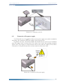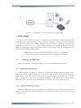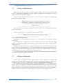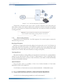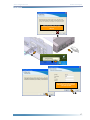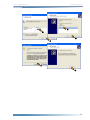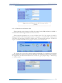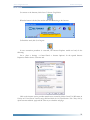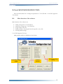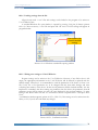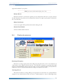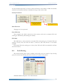
1
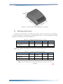
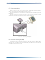
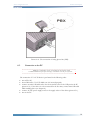
VoiceUSB User manual v1.2 History The company was established in April 15th, 1998 with a headquarters in Vilnius. The business started from production of telecommunication devices. In 2001 the company expanded its business into fields of wireless data transfer, electronic system design and production. Partnership contract with German company Pro-Sign GmbH was signed in 2002 to design graphic programming interface iCon-L and represent it in Eastern Europe. Teltonika, by becoming NOKIA partner in 2003, started integration of NOKIA M2M technology using NOKIA N12 module. This launched wireless technology design process in the company. Teltonika was invited by NOKIA to join presentation of M2M technology innovations in CeBIT 2004. This event marked recognition of a small Lithuanian company by international business community. Our vision Over 10 of new products and solutions were created by Teltonika in year 2004 employing EDGE technology. The company became one of the leaders in integration of M2M solutions with EDGE technology in Lithuania and whole Europe as well. Our vision is to provide our clients with electronic devices and solutions which are based on the latest achievements of science and technology, thus creating additional value for people and companies. Successful participation in two international exhibitions in year 2005 - CeBIT and HANNOVER MESSE - opened the company new possibilities to offer products and solutions for clients from all over the world. We aim to help people to integrate the latest technologies in real life, thus making it more comfortable, mobile and secure. In year 2005 Teltonika became an international Lithuanian – Finnish company. Several employees from NOKIA joined Teltonika team. Presently they successfully develop activity of new companies: Teltonika International GmbH (Düsseldorf) and Teltonika International Oy (Helsinki). We seek to make our solutions an inconceivable part of people’s lives. Voice configuration tool Product Description TABLE OF CONTENTS 1. 2. 3. 4. 5. LEGAL NOTICE....................................................................................................................................4 ABOUT THE MANUAL.......................................................................................................................4 INTRODUCTION .................................................................................................................................4 PACKAGE CONTENTS ......................................................................................................................5 TECHNICAL CHARACTERISTCS ...................................................................................................5 5.1. Data Transfer ...................................................................................................................................5 5.2. Mechanical characteristics ..............................................................................................................5 5.3. Operating characteristics ................................................................................................................6 5.4. Indication..........................................................................................................................................7 6. VoiceUSB PREPARATION FOR WORK ..........................................................................................8 6.1. Antenna connection........................................................................................................................8 6.2. Inserting SIM card...........................................................................................................................8 6.3. Connecting the phone ....................................................................................................................9 6.4. Connection of analog line (PBX)..................................................................................................9 6.5. Connection to the PC ...................................................................................................................10 6.6. Connection of the power supply.................................................................................................11 6.7. VoiceUSB connection examples...................................................................................................12 7. THE START...........................................................................................................................................13 7.1. Entering the PIN code .................................................................................................................13 7.1.1 Manual PIN code entering..................................................................................................13 7.1.2 Automatic PIN code entering ............................................................................................13 7.2. Calling in PHONE mode .............................................................................................................14 7.2.1 Phone mode parameters......................................................................................................14 7.3. Calling in Trunk mode ..................................................................................................................14 7.3.1. Trunk mode parameters......................................................................................................15 8. VoiceUSB INSTALLATION AND CONFIGURATION .............................................................15 9. MODEM CONTROL TOOL.............................................................................................................20 9.1. Connecting to the Internet...........................................................................................................20 9.1.1 Connection to the Internet order.......................................................................................21 9.2. SMS messaging ..............................................................................................................................23 9.3. Changing security options............................................................................................................25 9.3.1 PIN code control Disable/Enable:....................................................................................25 9.4. Program language setting .............................................................................................................26 9.5. GSM operator selection................................................................................................................26 9.6. Other program functions .............................................................................................................26 10. VoiceUSB CONFIGURATION TOOL.............................................................................................27 10.1. Main functions of the software...............................................................................................27 10.2. Operations with parameters ....................................................................................................28 10.2.1 VoiceUSB Configuration Tool preparation for operation....................................................28 10.2.2 Reading settings from the device .......................................................................................28 10.2.3 Saving settings in the the file ..............................................................................................29 10.2.4 Loading settings from the file.............................................................................................30 10.2.5 Writing new settings to VoiceUSB device .........................................................................30 10.2.6 Restoring default settings ....................................................................................................31 10.3. General parameters...................................................................................................................31 10.4. Trunk mode parameters ...........................................................................................................32 10.5. Prefix Blocking..........................................................................................................................33 10.6. Number blocking ......................................................................................................................34 10.7. Allowed numbers in Trunk mode...........................................................................................34 2 Voice configuration tool Product Description 11. VoiceUSB service menu..........................................................................................................................35 11.1. Changing Service menu password ..............................................................................................35 11.2. PIN code entering control.......................................................................................................35 11.3. Call duration indicating signal .................................................................................................36 11.4. Prefix blocking ..........................................................................................................................36 11.4.1 Entry supplement .................................................................................................................37 11.4.2 Deleting entry........................................................................................................................37 11.5. Number blocking ......................................................................................................................37 11.5.1 Entry supplement .................................................................................................................38 11.5.2 Delete entry ...........................................................................................................................38 11.6. Trunk mode allowed numbers list ..........................................................................................38 11.6.1 Entry supplement .................................................................................................................39 11.6.2 Delete entry ...........................................................................................................................39 11.7. Interval between dial and connection ....................................................................................40 11.8. Trunk mode control..................................................................................................................40 11.9. Caller ID display........................................................................................................................41 11.10. Prefix...........................................................................................................................................41 11.11. Polarity reverse ..........................................................................................................................42 11.13. Manufacturer parameters.........................................................................................................43 12. ACRONYMS ..........................................................................................................................................44 13. TECHNICAL SUPPORT ....................................................................................................................44 3 Voice configuration tool Product Description 1. LEGAL NOTICE Copyright © 2006 JSC “Teltonika“. All rights reserved. Reproduction, transfer, distribution or storage of part or all of the contents of this document in any form without the prior written permission of JSC “Teltonika“is prohibited. Other products and company names mentioned may be trademarks or trade names of their respective owners. 2. ABOUT THE MANUAL This manual describes VoiceUSB technical and software configuration, installation procedures. The manual also includes description of mechanical, electrical, radio frequency, antenna, PC configuration and software installation. VoiceUSB device is being continuously improved by increasing working quality and expanding functionality. Therefore a Firmware update procedure is created. 3. INTRODUCTION VoiceUSB device performs the following functions: emulates phone line; can be used as a modem for connection to the Internet and data transmission; connects PSTN and GSM networks. Basically VoiceUSB is a phone line emulator that allows to call and receive calls via GSM network while connected to the analogical phone. VoiceUSB device supports number display function. The second function of VoiceUSB is a GSM modem. The device is connected to PC using USB interface. Modem Control Tool is used for connection to the Internet and SMS messaging. VoiceUSB supports the following data transmission types: EDGE, GPRS, CSD, HSCSD and CSF. It is possible to call to/from any number in PBX to GSM network and vice versa while Trunk mode is activated. VoiceUSB device has many parameters that can be configured with VoiceUSB Configuration Tool software or telephone connected to it. 4 Voice configuration tool Product Description 4. PACKAGE CONTENTS VoiceUSB device is delivered to the client in cardboard box with all required supplements necessary for work. Package consists of: cardboard box; VoiceUSB device; USB A Ù USB mini B connection cable; AC/DC power supply adapter; CD with User Manual and drivers; external GSM antenna. Note: the manufacturer does not provide SIM card which is necessary for connecting to the GSM network! SIM card can be obtained from your GSM operator! If any of the components is missing from your package, please contact manufacturer’s representative or salesperson. 5. TECHNICAL CHARACTERISTCS 5.1. Data Transfer VoiceUSB device supports the following data transmission types used in GSM networks. Data type used depends on your GSM operator and data transfer capacity in chosen GSM network: EDGE class 6; GPRS class 10; HSCSD class 2; CSD; CSF. Note: Modem always works in fixed 230400 bps speed in USB interface. VoiceUSB device also has an incoming number detection function. A ES300778-1/2 standard and MDMF format is used for it. 5.2. Mechanical characteristics VoiceUSB device case is made of plastic. External view and measurements of the device are shown in picture 4.2.1. 5 Voice configuration tool Product Description 32 Picture 4.2.1. External view and measurements of the device 5.3. Operating characteristics The device is powered from a 12 V (DC) power supply. The PC to which the VoiceUSB device is connected must have a USB interface corresponding to USB 1.1 or USB 2.0 standards. Electrical parameters of the device are shown in Table 4.3.1. Table 4.3.1. Electrical characteristics of VoiceUSB Parameter Min Nominal Max Power Supply Voltage +9 +12 +15 Average Power 1.4 7.2 consumption Current Consumption 100 120 600 Units V W mA Operating conditions and weight of the device are shown in Table 4.3.2 . Table 4.3.2. Operating conditions and weight Parameter Min Nominal Max Weight 135±10 Marginal Operating -25 +55 Temperature Storage Temperature -40 +70 Units g ºC ºC Note: In case the conditions do not meet the characteristics given above, the device can be damaged! 6 Voice configuration tool 5.4. Product Description Indication VoiceUSB has 4 LEDs for device status indication. They are located at the top part of the device. The indication statuses of the device are described in Table 5.4.1. Table 5.4.1. Device status description Description Power supply on Device is preparing for work Device is ready for work (GSM network is detected, general configuration is set) Mode blinking Device is connected to the Internet or is on call Mode on USB interface connected to the device On/Hook LED on Phone is picked up Error LED blinking Device is awaiting for PIN code Error LED on No SIM card or wrong PIN code Status Power LED is on Status blinking Status on 7 Voice configuration tool Product Description 6. VoiceUSB PREPARATION FOR WORK Connect antenna to VoiceUSB device (see chapter 6.1). Then insert SIM card and make sure that it is inserted properly. Depending on action to be performed the following devices can be connected to the device: 6.1. phone through RJ11 connector marked as Phone; analog phone line (PBX) is through RJ11 connector marked as Line (for Trunk mode); PC through the USB port. Antenna connection It is recommended to install the antenna inside the building. In case the antenna has to be installed outside, it must be grounded and secured against lightning. Antenna is connected using the standard SMA jack. Antenna connection is shown in picture 6.1.1. Picture 6.1.1. Antenna connection 6.2. Inserting SIM card SIM card must be inserted as shown in picture 6.2.1. Make sure that it is inserted properly. Picture 6.2.1. Inserting SIM card 8 Voice configuration tool Product Description 6.3. Connecting the phone Phone is connected to the VoiceUSB device through a standard RJ11 connector marked as PHONE. For connection two middle connection contacts are used. The phone connected to the VoiceUSB device can make and receive incoming calls from the GSM network. The phone connected to the device must meet the LST EN 60950-1 and LST EN 41003 standards. The connection of the phone to the device is shown in picture 6.3.1. Picture 6.3.1. Connecting the telephone 6.4. Connection of analog line (PBX) VoiceUSB device can also be directly connected to the analog phone line (PBX). PBX is connected to the VoiceUSB device through the standard RJ11 jack marked as LINE. For connection two middle connection contacts are used. 9 Voice configuration tool Product Description Picture 6.4.1. The connection of analog phone line (PBX) 6.5. Connection to the PC Note: It is recommended to read the VoiceUSB INSTALLATION AND CONFIGURATION chapter before connecting VoiceUSB device to the PC for the first time The connection of VoiceUSB device is performed in the following order: turn off the PC; insert SIM card to VoiceUSB. Make sure it is inserted properly; connect one mini USB cable end to the device and the other to the USB port in the PC (picture 6.5.1). If the device is to be connected for the first time, connect mini USB cable while installing driver (see chapter 8); connect AC/DC power supply source to the supply socket of the device (picture 6.5.1); turn on the PC. 10 Voice configuration tool Product Description Picture 6.5.1. Connection to the PC 6.6. Connection of the power supply 300 mA direct current power supply source which is included in VoiceUSB module uses 12V the package. The connection of the power supply is shown in picture 6.6.1. To guarantee the safety, safety devices (bipolar disconnection device) must be set in installation place and supply circuit to prevent from over current, short circuit and grounding corruption (picture 6.6.2). The capacity of the disconnection device must match the capacity of the devices connected to it. The space between device contacts cannot be shorter than 3 mm. AC/DC 9V adapter Picture 6.6.1. Connection of the power supply 11 Voice configuration tool Product Description VoiceUSB Picture 6.6.2. Safe connection of the power supply of VoiceUSB to the PC 6.7. VoiceUSB connection examples There are several possible module connection ways, the main are shown in pictures 6.7.1-6.7.3. Connection method depends on user needs. The simplest connection way is to connect one phone (shown in picture 6.7.1). Phone is connected to the device through standard RJ11 jack marked as PHONE. Several phones can be connected to the VoiceUSB with the help of PBX station. PBX station is connected to the device through standard RJ11 jack marked as PHONE. PBX station connection example is shown in picture 6.7.2. The third connection way is used when the device is working in Trunk mode (picture 6.7.3). In this case, the device is connected to the analog phone line (PBX) through standard RJ11 jack marked as LINE. Picture 6.7.1. Example of one phone connection to the VoiceUSB module Picture 6.7.2. Example of several phones connected to the VoiceUSB module using the PBX station 12 Voice configuration tool Product Description Picture 6.7.3. Example of VoiceUSB connection in Trunk mode 7. THE START When the VoiceUSB device is ready for operation, that is, SIM card inserted, antenna, phone, analog phone line or PC (depending on needs) and power supply are connected, the Power LED light is on and Status LED starts blinking indicating that the module is preparing for work. The initialization can take up to 20 seconds. During initialization the module checks the SIM card, detects the appropriate GSM network and checks the working parameters. When initialization is done, the Status LED becomes constant. Note. If PIN code request is activated on the SIM card, Error LED starts blinking and phone signal is busy. That means that the module is waiting for the PIN code. 7.1. Entering the PIN code There are two possible PIN code entering ways in VoiceUSB: manual and automatic. 7.1.1 Manual PIN code entering If SIM card PIN code request is activated, Error LED starts blinking and phone signal is busy. This means, that the module is waiting for the PIN code which must be entered with the help of the phone buttons. If the PIN code entered correctly, a long phone signal is on the line and VoiceUSB is ready to operate. If the PIN code was entered incorrectly, the Error LED becomes constant and the phone line is busy. PIN code can be entered using service menu or VoiceUSB Configuration Tools. 7.1.2 Automatic PIN code entering If SIM card PIN code request is activated, the VoiceUSB device uses the PIN code stored in its memory. The PIN code can be entered into VoiceUSB memory using service menu or VoiceUSB Configuration Tools. 13 Voice configuration tool 7.2. Product Description Calling in PHONE mode In this mode, the device emulates the analog call while making a phone call from GSM network to the VoiceUSB devise. Depending on needs, a phone or PBX can be connected to the device through the RJ11 jack marked as PHONE. In order to make a phone calls, connect the VoiceUSB to the phone or PBX, insert the SIM card and connect the power supply. Note: Calling mode does not work in the following situations: a) when VoiceUSB device is connected to the Internet; b) when Trunk mode is on; c) when working in service menu; d) while working with VoiceUSB Configuration Tool Wait until the device gets ready for work. If needed, enter PIN code of the SIM card inserted in the VoiceUSB device. Calling is possible when the long signal is heard on the phone line. Note: Making international phone calls, instead of +, dial 00 7.2.1 Phone mode parameters All parameters can be changed with the help of VoiceUSB Configuration Tool or phone connected to the device. VoiceUSB device has a Number Prefix function. When this function is activated, prefix will be added to each outgoing number. This function can be activated in Service menu or with VoiceUSB Configuration Tool. In calling mode the device allows to form a blocked numbers list. This list can be made in Service menu or with VoiceUSB Configuration Tool. The list of blocked prefixes can also be made in this mode. Numbers that start with the blocked prefixes will not be forwarded to GSM network. The prefix list can be formed in Service menu or with VoiceUSB Configuration Tools. VoiceUSB device has a Minute notification function. After activating the function, during the phone call a short beep signal will appear each minute. 7.3. Calling in Trunk mode In this mode, it is possible to make a phone call to VoiceUSB module from mobile GSM network and the module will commutate with the internal or PSTN network number. Also there is a possibility to call from internal or PSTN network numbers (through PBX) to GSM network. For example, you have to make a phone call from GSM network to the internal network number. Dial VoiceUSB number (number of the SIM card inserted into the device) in your mobile phone. The device will detect the incoming call and automatically will answer. When the long tone signal is heard, you can start dialing internal phone number. In this case you will save on calls to another networks or countries. For Trunk mode RJ11 connection is used (marked as LINE). 14 Voice configuration tool Product Description Picture 7.3.1. VoiceUSB connection in Trunk mode Trunk mode is activated in Service menu or with VoiceUSB Configuration Tool. In this mode, the device allows to form a list of phone numbers that are allowed to use the Trunk mode. If the phone call to the VoiceUSB device was made from the number that is not listed, the call will not be directed to analog phone line. Note: While using the Trunk mode, the PIN code request for GSM SIM card must be disabled or automatic PIN code entering should be set in the Service menu! 7.3.1. Trunk mode parameters All parameters can be changed with VoiceUSB Configuration Tool or with the phone connected to the device using Service menu. Busy Signal Frequency When the user hangs up the phone after calling from the phone line to the VoiceUSB device (in Trunk mode), line makes a busy signal. VoiceUSB device recognizes the set busy signal frequency and automatically hangs up the phone and gets ready for another incoming call. By default, busy signal frequency is set to 425 Hz. This menu item allows to change the frequency. Tone Signal Level This menu item allows to change dialing tone signal level in Trunk mode. It is recommended to change it in case when the device does not react to a dialed number or some of dialed digits (then the level should be decreased), or because of line interferences some number is dialed automatically (then the level should be increased). Allowed Numbers Using the phone, there is a possibility to form a list of allowed numbers of Trunk mode. Maximum 10 entries can be added to it. VoiceUSB device in Trunk mode was tested on PANASONIK KX – TEM284 PBX station. 8. VoiceUSB INSTALLATION AND CONFIGURATION VoiceUSB Tools is software package installed on your PC and contain of: 15 Voice configuration tool Product Description VoiceUSB device drivers; VoiceUSB Configuration Tool; Modem Control Tool; VoiceUSB device documentation. Note: Disconnect VoiceUSB from your PC before installing VoiceUSB Tools. INSTALLATION insert SIM card into VoiceUSB. Make sure the SIM card is inserted properly; connect antenna and power supply; insert CD into the CD-ROM; with the help of Installation Wizard, install the software and the drivers; connect VoiceUSB device to your PC during installation at requested stage. 2 1 4 3 16 Voice configuration tool Product Description When this window opens first of all connect the „VoiceUSB“device to your PC USB port! 5 7 6 8 If you do not have the required information, you can get it from your GSM operator 10 9 17 Voice configuration tool Product Description 11 In order to use Internet, the VoiceUSB device must be installed as a modem in Windows XP operating system. In order to install VoiceUSB device as a modem, open Phone and Modem Options window („Start → Settings → Control Panel → Phone and Modem Options“). Click Add... in the opened window. A Add Hardware Wizard window will appear: 1 2 18 Voice configuration tool Product Description 5 3 6 4 7 8 19 Voice configuration tool Product Description 9. MODEM CONTROL TOOL 9.1. Connecting to the Internet This chapter provides the general information about how to prepare the PC for the connection to the Internet using the Modem Control Tool. Before starting the work, make sure that: the GSM SIM card with activated data transfer service is available; VoiceUSB device is ready to operate – SIM card is inserted, the device is connected to the PC, the required drivers and software is installed; the TCP/IP protocol is installed in PC. Two connection ways to the Internet using the VoiceUSB device are possible: GPRS/EDGE packet data transfer. In this case you have to know the APN, User name and the Password; HSCSD/CSD data transfer. You have to know the phone connection centre Phone number. If you are using the GPRS/EDGE data transfer, then the APN, user name and password has to be set. Double click on Modem Control Tool pictogram located on the The Modem Control Tools will open. Enter PIN code if requested and click Program Settings: desktop. enter access point name (APN); enter internet service provider (ISP) name and a phone number [*99#], if they were not entered automatically; enter user name and password if required; click Update Data. 20 Voice configuration tool Product Description Note: Ask your GSM operator for APN, User name and User password! 9.1.1 Connection to the Internet order When connecting to the Internet, the PIN code request for the SIM card must be disabled or automatic PIN code entering should be set in the Service menu. When connection parameters are set, run the Modem Control Tool. The program is started by clicking the Modem Control Tool pictogram (or Start → Programs → VoiceUSB Tools → Modem Control Tool). When the pictogram is clicked, the Modem Control Tool main window will open. If PIN code request is enabled in the SIM card, the program will ask to enter the PIN code. The program has to detect the connected modem automatically. If the modem was connected after the program was started, it will take some time while the modem gets ready to work. Therefore, the program may not detect the modem at once. In such case, go to„Program settings → Modem settings → Autodetect modem“. 21 Voice configuration tool Product Description To connect to the Internet, click Connect To Internet Using Modem: When the button is clicked, the modem will start connecting to the Internet. When connection is established, message “Connected To Internet” appears To finish the work, click Exit Program: In case connection procedure is successful, but Internet Explorer would not load, do the following: Go to „Start → Settings → Control Panel → Internet Options“. In the opened Internet Properties window choose Connections tab. Click on the internet service provider name that was created by Modem Control Tool (ISP name) in Dial-up and Virtual Private Network settings field and click the Set Default button. Tick Always dial my default connection and click Apply and OK. Then try to reload the web page. 22 Voice configuration tool 9.2. Product Description SMS messaging It is possible to send and receive SMS messages using VoiceUSB device. Before starting using this VoiceUSB function, it is necessary to disconnect from the Internet. To do this, simple click Disconnect from Internet button. Before starting sending SMS, check if the message centre number is entered. Click Program Settings and SMS Settings. In the opened window, the SMS centre number should be entered automatically. If it is not, ask the number from your GSM operator. To write and read the received SMS messages, click the Short Messages Service in Modem Control Tool main window: A window for SMS writing or the last used window will open. In the upper field type the receiver’s phone number starting from the area code (+ is not required). Enter the message text in the box bellow. The number indicating left symbols is on the right of the box (total 160). When the message is typed, click Send. A confirmation message: Message Sent Successfully or Message Sending Failed should appear. 23 Voice configuration tool Product Description There is also a possibility to read received, sent and unsent SMS messages. Click Short Messages Service and Unread SMS. It will take some time while the program will refresh the messages. In the opened window, a list with all recently received and unread messages will be displayed. To read the message, mark it and the message text will be displayed in the right frame of the main program window. All read messages are automatically moved to Inbox. To delete marked message, click a Delete SMS button. In order to delete more than one message at the same time, hold Shift while marking the messages and then click Delete SMS. 24 Voice configuration tool 9.3. Product Description Changing security options Unique PIN codes are used to secure SIM cards. A PIN code must be entered before starting using the GSM network services. VoiceUSB device supports two main GSM security modes: PIN code request disabled and PIN code request enabled. If the PIN code request disabled mode is chosen, PIN code will be entered once and will not be required for later connections; otherwise PIN code will be requested every time switching on the modem. Modem Control Tool is used to change security options. 9.3.1 PIN code control Disable/Enable: Disable start the Modem Control Tool; choose Program Settings; choose Security Settings; choose PIN Request Disable; click Update Data. Enable start the Modem Control Tool; choose Program Settings; choose Security Settings; choose PIN Request Enable; click Update Data. Enter the PIN code in displayed window and click OK. 25 Voice configuration tool 9.4. Product Description Program language setting Program language can be set in Program Settings: Note: Default program language is English. 9.5. GSM operator selection A GSM operator can be selected in Program Settings and GSM Oper. Selection. When Get GSM Operators List is clicked, the program will display all GSM operators to which it is possible to connect. An available operator will be chosen after clicking the Select Available GSM Operator. 9.6. Other program functions About This Program button Program version, manufacturer’s address, phone number, e-mail and web page are displayed. On the right side of Modem Control Tool main window, a GSM signal indicator is displayed: While using the modem it is very important to pay attention to the signal, otherwise, the connection to the Internet may be unstable and SMS messages may fail at sending. In such cases it is recommended to relocate the modem or its external antenna (if there is one) to more open place. 26 Voice configuration tool Product Description 10.VoiceUSB CONFIGURATION TOOL This section describes how to change the parameters of VoiceUSB with a VoiceUSB Configuration Tool software. 10.1. Main functions of the software Main functions of the software are: reading settings from VoiceUSB device; writing new settings into VoiceUSB device; saving settings in the file; loading settings to the program from the specific (*.vsav) file; restoring default settings. VoiceUSB Configuration Tool view Main program window is divided into three frames. VoiceUSB settings group Control buttons Settings in setting group 27 Voice configuration tool 10.2. Product Description Operations with parameters 10.2.1 VoiceUSB Configuration Tool preparation for operation turn VoiceUSB device on; connect VoiceUSB device to USB port. The device drivers must be already installed and the number of the virtual COM port should be known; from a drop-down menu (picture 10.2.1.1) choose COM port to which the device is connected. Click Connect. The program connects to the VoiceUSB device. When connection is established, Connect changes into Disconnect (picture 10.2.1.2) Picture 10.2.1.1. Choosing the COM port Picture 10.2.1.2. Connect/Disconnect after connection 10.2.2 Reading settings from the device To read parameters from the device make sure it is connected as shown in picture 10.2.1.2 nad then click on Read Device. VoiceUSB device settings should appear in information part of program window (picture 10.2.2.1). 28 Voice configuration tool Product Description Parameters read from VoiceUSB device Picture 10.2.2.1. Program window after Read Device command 10.2.3 Saving settings in the the file All parameters from program window can be saved in special file with “*.vsav” extension. Press button Save to file. A standard Window file save option window appears (picture 10.2.3.1). Name the file and choose folder to store the setting file. Special files with savedVoiceUSB settings Picture 10.2.3.1. Windows standard file saving window 29 Voice configuration tool Product Description 10.2.4 Loading settings from the file All previously saved “*.vsav” files with settings can be loaded to the program to be written to VoiceUSB device later. A standard Windows file open window is opened by pressing Load from file button (picture 10.2.4.1). Choose necessary “*.vsav”file and press OK. All saved VoiceUSB settings will appear in program window. Special files with saved VoiceUSB settings Picture 10.2.4.1. Windows standard file opening window 10.2.5 Writing new settings to VoiceUSB device Program settings can be written to the VoiceUSB device. However, if any field or box is left empty, the appropriate information in the VoiceUSB device will be deleted or replaced with the default settings. Therefore, it is recommended to read the parameters of the device (or from .vsav file) if only one or few parameters are to be changed and only then make changes and write everything into memory of the device. In that case all parameters will be checked carefully. It is also important to remember, that when writing any parameters into the device, the parameters from all parameter groups will be written (not only the ones displayed in the program window). To write setting to the device make sure that it is connected as shown on picture 10.2.1.2 and press Write Device. A confirmation window appears (picture 10.2.5.1). Click Yes, if the settings are to be written into the device, or No, if you do not want make any changes. Picture 10.2.5.1. Confirmation window 30 Voice configuration tool Product Description 10.2.6 Restoring default settings Make sure device drivers are installed and the device is connected to appropriate COM port. Press button Restore Defaults. A confirmation window should appears (picture 10.2.6.1). Click Yes. Picture 10.2.6.1. Confirmation window 10.3. General parameters Number dial interval Sets the time interval after which the VoiceUSB device starts calling the dialed number. Parameter is set in seconds. E.g. Num dial interval value is set to 3 seconds. You want to dial a 123456 number. If more that 3 seconds passes after pressing 1, the device detects the digit as a dialed number. To avoid such misunderstandings, the dialing intervals cannot be longer than 3 seconds. Number Prefix If a prefix is required to each dialing number, enter it in the Number Prefix field. E.g. +370 value is entered in the Number Prefix field. If you dial 123456, the device will dial +370123456. Note: Num prefix Enable field must be activated Device Modes The device can work in both PHONE and Trunk modes. A desirable work mode can be chosen in Device Mode field using VoiceUSB Configuration Tool. Connection Mode VoiceUSB device can work as a USB modem or Fax. If Data Mode is chosen, the device switches to data transfer mode and works as a USB modem. If FAX mode is chosen, the device switches to fax mode (it can send and receive FAX data packets). Note: This version of VoiceUSB does not support the FAX mode. It will be installed in 3.02 version. Caller ID type Device supports caller ID display function. The number can be displayed in the phone connected to the VoiceUSB device. Select a modulation type in Caller ID type field according to the 31 Voice configuration tool Product Description supported standard of your phone. Note If you want to disable number display, choose None Polarity Reverse When this function is activated, the polarity reverse will perform when the over party answers the call. Otherwise, the polarity reverse will perform when the user picks up the phone connected to the VoiceUSB device. Minute Notification A short tone signal will be produced each minute during the call. Number Prefix Enable Activates Number Prefix function. 10.4. Trunk mode parameters Trunk Mode settings button Trunk Mode parameters Busy Signal Frequency When the user hangs up the phone after calling from the phone line to the VoiceUSB device (in Trunk mode), a busy signal is heard on the line. VoiceUSB device recognizes a particular busy signal frequency and automatically hangs up and gets ready to receive another incoming call. By default the frequency is 425 Hz. This menu item allows to change the frequency (425, 480). Tone Signal Level This menu item allows to change dialing tone signal level in Trunk mode. It is recommended to change it in case when the device does not react to a dialed number or some of dialed digits (then 32 Voice configuration tool Product Description the level should be decreased), or because of line interferences some number is dialed automatically (then the level should be increased). Available level range is from 800 to 1800. Security Parameters Security parameters changing button Security parameters Menu Password Changing Service menu password Enter PIN Code Value entered in this field is written into device memory and used as automatic PIN code entering (see PIN Mode), while writing into memory. PIN Mode This field allows to choose manual or automatic PIN code entering way. If manual PIN code entering is chosen, then each time the device is turned on, PIN code will have to be entered manually. If automatic PIN code entering way is chosen, then PIN code will be automatically read from the device memory. 10.5. Prefix Blocking This function blocks phone calls to numbers with prefixes that are entered in Prefix Blocking group. To activate Prefix Blocking, tick the box Enable as it is shown in the picture. All dialed numbers with prefix “370” will be blocked. 33 Voice configuration tool 10.6. Product Description Number blocking This function blocks the calls to the numbers set in Number Blocking section. To activate the Number Blocking function, tick the box Enable. 10.7. Allowed numbers in Trunk mode This function allows to use Trunk mode only for those users that are in the Allowed numbers group list. To activate Allowed number function, tick the box Enable. 34 Voice configuration tool Product Description 11. VoiceUSB service menu VoiceUSB parameters can be changed with the help of ordinary phone. After turning the device on, wait until it gets ready to work. If needed, enter the PIN code (see chapter 4.1.). When long tone signal is heard on the line, Service menu password can be entered. Standard password is ##1111#. When password is entered, VoiceUSB control through the phone is activated and VoiceUSB main Service menu is open. To exit from any part of the Service menu, hang up the phone or dial **. Long beeps are heard while browsing options in Service menu. When any function is being activated, short beeps are heard on the line. Command list of the main Service menu of the device is given in the table Command 1# 2# 3# 4# 5# 6# 7# 8# 9# 10# 11# 12# 11.1. Description Changing Service menu password PIN code entering control Turning on/off the call duration signal Prefix blocking Number blocking Trunk mode allowed number list formation Set time interval between dialing and connecting Trunk mode control Caller ID display control Prefix Polarity reversal Restoring defaults Changing Service menu password ##1111# 1# <New 4 digit menu password > # In order to change Service menu password, dial 1# in main Service menu. Now enter new 4 digit user password and press #. New password will be saved in device memory. When the new password is saved, the device returns to the main menu. 11.2. PIN code entering control PIN code automatic entering of the GSM SIM card inserted in the VoiceUSB device, can be enabled/disabled with the help of the phone. To get to the PIN code entering control menu, dial 2# in the main menu. ##1111# 2# ... 0# If 1# is dialed in the main menu, the manual PIN code entering is activated and each time the device is being turned on, the PIN code will have to be entered manually. 35 Voice configuration tool Product Description ##1111# 2# 1# 0# In PIN code entering control menu dial 2#, and the automatic PIN code entering will be activated, that is, PIN code will be automatically read from the device memory. ##1111# 2# 2# 0# Note: in order to use automatic PIN code entering, in PIN code entering control menu dial 3#, enter the PIN code and press #. Now the PIN code will be saved in device VoiceUSB memory. To return to main menu, press 0#. ##1111# 2# 2# 0# 11.3. Call duration indicating signal Dial 3# in the main menu in order to get to Signal indicating call duration menu. ##1111# 3# ... 0# The signal indicating call duration can be turned on/off with the help of the phone. The call duration is indicating with a beep per minute. In signal indicating call duration menu press 1# to enable the function. ##1111# 3# 1# 0# Press 2# to disable the function. ##1111# 3# 2# 0# 11.4. Prefix blocking Prefix blocking can be performed with the help of the phone. In order to get to the Prefix blocking menu, dial 4# in the main menu. Total 10 entries can be done. ##1111# 4# ... 0# To enable the function, press 1# in Prefix blocking menu. 36 Voice configuration tool Product Description ##1111# 4# 1# 0# Dial 2# in order to disable the function. ##1111# 4# 2# 0# The phone call will not be made if the dialed number will have a blocked prefix. Maximum length of the blocking prefix is 6 digits. 11.4.1 Entry supplement To add new entry, dial 3# in Prefix blocking menu. ##1111# 4# 3# ... 0# This command activates entry supplement function. When the function is activated, choose entry place in the list. This is done by dialing the place number from 0 to 9 and pressing #. In such case particular placement in the list is chosen for the blocked prefix. ##1111# 4# 3# (0 ... 9) # … 0# Now you can enter a prefix and dial #. ##1111# 4# 3# (0 ... 9) # <prefix> # 0# 11.4.2 Deleting entry Dial 4# in order to delete prefix in Prefix blocking menu. ##1111# 4# 4# ... 0# 4# command activates entry deleting function. When the function is activated choose the entry place in the list. This is done by dialing an entry place number from 0 to 9 and pressing #. ##1111# 4# 4# (0 ... 9) # 0# The particular blocked prefix will be deleted from the particular place in the list. 11.5. Number blocking Number blocking can be performed with the help of the phone. The function is activated by dialing 5#. 37 Voice configuration tool Product Description ##1111# 5# ... 0# In total 10 entries are allowed. To enable number blocking, dial 1#. ##1111# 5# 1# 0# Dial 2# to disable number blocking. The blocking numbers can consist of max 15 digits. ##1111# 5# 2# 0# 11.5.1 Entry supplement Dial 3# to add new entry. ##1111# 5# 3# … 0# This command activates number adding function. When the function is activated, place in the list has to be chosen. This is done by dialing the place number in the list from 0 to 9 and pressing #. ##1111# 5# 3# (0…9) # … 0# Now add a new phone number and dial #. Number starts with the prefix, + is omitted. ##1111# 5# 3# (0…9) # 370 651 12345 # 0# 11.5.2 Delete entry Entry is deleted by dialing 4#. ##1111# 5# 4# … 0# This command activates the entry deleting function. When the function is activated, choose entry place number in the list. This is done by dialing place number in the list from 0 to 9 and pressing #. ##1111# 5# 4# (0…9) # 0# 11.6. Trunk mode allowed numbers list Trunk mode allowed numbers list can be formed with the help of the phone. In total 10 numbers can be entered. The function is activated by dialing 6#. 38 Voice configuration tool Product Description ##1111# 6# ... 0# Dial 1# to enable Allowed numbers list function. ##1111# 6# 1# 0# Dial 2# to disable Allowed numbers list function. ##1111# 6# 2# 0# When the mode is activated, the phone calls can be made only from the numbers in the formed list. Other numbers will be ignored. 11.6.1 Entry supplement Dial 3# to add new entry. A fifth place in the list will be selected. Now enter the phone number and dial #. ##1111# 6# 3# … 0# This command activates entry adding function. When the function is activated, choose entry place number in the list. This is done by dialing place number in the list from 0 to 9 and pressing #. The particular place in the list will be chosen for new entry. ##1111# 6# 3# (0…9) # … 0# Now enter the phone number and press #. ##1111# 6# 3# (0…9) # 370 651 12345 # 0# 11.6.2 Delete entry Entry is deleted by dialing 4# with the phone. When 4# is entered, a beep is heard on the line. This command activates the entry deleting function. ##1111# 6# 4# … 0# When the function is activated, choose entry place number in the list. This is done by dialing place number in the list from 0 to 9 and pressing #. ##1111# 6# 4# (0…9) # 0# 39 Voice configuration tool 11.7. Product Description Interval between dial and connection It is possible to change time interval between dialing and connecting with the help of the phone. Time is set in seconds. Dial 7# in order to change the time interval. ##1111# 7# ... 0# Now enter numbers from 1to 5 and press #. ##1111# 7# (1...5) # 0# 11.8. Trunk mode control It is possible to enable/disable Trunk mode of the VoiceUSB device. Dial 8# to activate the Service menu function. ##1111# 8# ... 0# To get to Trunk mode control menu dial 8#. 1# will enable the Trunk mode. ##1111# 8# 1# 0# Trunk mode is disabled with 2#. ##1111# 8# 2# 0# When the user hangs up the phone after calling from the phone line to the VoiceUSB device (in Trunk mode), line makes a busy signal. VoiceUSB device recognizes the set busy signal frequency and automatically hangs up the phone and gets ready for another incoming call. By default, busy signal frequency is set to 425 Hz. Dial 3# in Trunk mode control menu in order to change the frequency. ##1111# 8# 3# 0# Enter frequency and press #. ##1111# 8# 3# <Frequency> # 0# Dialing 4# in Trunk mode control menu allows to change incoming call detection level value in Trunk mode. 40 Voice configuration tool Product Description ##1111# 8# 4# <level value> # 0# It is recommended to change it in case when the device does not react to a dialed number or some of dialed digits (then the level should be decreased), or because of line interferences some number is dialed automatically (then the level should be increased). New added level value can vary from 800 to 1800. 11.9. Caller ID display VoiceUSB device has a Caller ID detection function. The function allows to see the incoming phone number. In order to use the function, telephones must meet the standards, which are given in Table 8. By default this function is not active. Dial 9# in Service menu in order to get to Caller ID menu. ##1111# 9# ... 0# Dial 1# to disable the function. ##1111# 9# 1# 0# Dial 2# to enable FSK function. ##1111# 9# 2# 0# Dial 3# to enable DTMF function. ##1111# 9# 3# 0# 11.10. Prefix It is possible in VoiceUSB device to activate the function that would automatically add prefix to dialed number. To do so, dial 10# in main Service menu. ##1111# 10# ... 0# Now dial 1# to activate prefix adding. ##1111# 10# 1# 0# Dial 2# in Prefix menu to disable the function. 41 Voice configuration tool Product Description ##1111# 10# 2# 0# To add a prefix dial 3# Prefix and #. ##1111# 10# 3# <Prefix># 0# 1#. E.g. In order to add “370” prefix, you have to dial: ##1111#10#3#370#; and for activation: When dialing 123456 on the phone connected to the VoiceUSB device, the device will dial 370123456. 11.11. Polarity reverse After activating this function, the polarity reverse will perform when the over party will answer the call. Otherwise, the polarity reverse will perform when the user picks up the phone connected to the VoiceUSB device. To enter the mode control menu, dial 11# in the main Service menu. ##1111# 11# ... 0# To enable the mode, dial 1# in Poliarity changing mode menu. ##1111# 11# 1# 0# To disable the mode, dial 2# in Poliarity changing mode menu. ##1111# 11# 2# 0# 11.12. Restore default settings Dial 12# to restore default settings. ##1111# 12# 42 Voice configuration tool 11.13. Product Description Manufacturer parameters Service menu password PIN code entering PIN code Signal indicating call duration Number blocking Prefix blocking „Trunk“ mode allow list Time interval between dial and connecting „Trunk“ mode Busy signal frequency Signal tone level setting Incoming number display Number code Polarity reversed Manufacturer parameters 1111 Manual XXXX Off Off Off Off 3 Off 425 900 FSK Off On 43 Voice configuration tool 12. Product Description ACRONYMS EDGE GPRS HSCSD CSD CSF MDMF GSM PBX SIM PIN AC/DC APN PSTN FSK DTMF - Enhanced Data rates for GSM Evolution - General Packet Radio Service - High speed Circuit Switched Data - Circuit Switched Data - Circuit Switched Fax - Multiple Data Message Format - Global System for Mobile communications - Private Branch Exchange - Subscriber Identity Module - Personal Identification Number - Alternating Current/Direct Current - Access Point Name - Public switched telephone network - Frequency Shift Keying - Dual Tone Multiple Frequency 13.TECHNICAL SUPPORT This sign on the package means that it is necessary to read the User’s Manual contained on CD before you start using the device. This sign on the package means, that used electronic and electric equipment should be stored separately. If you encounter any problems while using the device and you are not able to solve them yourself, then you are always welcome to contact our technical support department by e-mail [email protected]. We will be glad to help you. 44