1
United States Patent [191
[11]
Sandbach et al.
[45]
[54] STEP AND REPEAT APPARATUS
[56]
Poole, Maccles?eld, both of United
3, m 7,
Um58PAAmmLmmDmomw”M. . NWTs
2 wH 6
118/697 X
Primary
4,485,387
Examiner—John
11/1984 Drumheller
P. McIntosh
[73] Assignee: Co-Ordinate Technology Ltd.,
Lancaster, England
Attorney, Agent, or Firm-Harry M. Weiss & Associates
[5
[21] Appl. No.: 747,662
[22] Filed:
4,694,776
Sep. 22, 1987
References Cited
[75] Inventors: Rex H. Sandbach, Stockport; Alan
Kingdom
Patent Number:
Date of Patent:
ABSTRACT
Step and repeat apparatus used for performance opera
Jun. 21, 1985
tions upon a generally planar component such as a mi
croprocessor wafer comprises a support for a work
[30]
Foreign Application Priority Data
1JM.120 u] my
a
[rL 5
.2mU1tF,f0.mS1CCd9 we“in . [SmGGemBm]s-cm h mUUm
"$a2nAd“. m1m/%"1a5“9 B620,mm0 6520“9n5 1465/ m/ 5u.om|,U5.12.768,91
" 8 CAL8/O 391.6 4
mm
“
KKm
ddH m
m
‘mm m
mm
Hm
A1
oo01 mm
"8m
piece, the support being attached by means of an arm to
eam .m€npsale?mnao ans-cHmSpa?I.Ctlar am2wmam m ..mme ma mwDemwOrP.UEWMvmOSetnm.1uw ghsheOFrdsc.lugt.ummPambPedeommt fwotn.mwas etOdam.rgn
mam.
mmo
pt
mrb
nm
Aver
mam
s,t060O1
.1r
tpO
PnV.
wm?fw
Of
1
4,694,776
STEP AND REPEAT APPARATUS
BACKGROUND AND SUMMARY
This invention relates to step and repeat apparatus of
the kind used for performance of operations upon an
approximately planar component. Such a component
may be one of a large number each having features
located in a not necessarily regular array on the planar
surface. The apparatus may be used for performing
operations repeatedly on successive components. Ex,
amples of step and repeat apparatus include micro
processor wafer probes, printed circuit manufacturing
apparatus laser trimmers and other apparatus for manu
facture of hybrid circuits.
Wafer probe apparatus is required to move and accu
rately position a wafer in relation to a probe head. Once
2
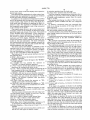
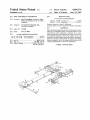
DETAILED DESCRIPTION
The apparatus illustrated in the drawing (which is not
to scale) comprises a support for a workpiece 1 located
at the end of an arm 2 which is pivotally mounted by
means of a hinge 3 remote from the support 1 but lo
cated in the horizontal plane of the latter when engag
ing the probe to ensure vertical movement of the wafer
as it contacts the probe. The workpiece may be secured
to the support by application of a vacuum from a suc
tion device.
A counterbalance 4 is arranged so that the arm 2 and
support 1 pivot about their centre of gravity. This al
lows the arm to have a relatively simple and inexpensive
sheet metal construction. The counterbalance of alter
native embodiments of the invention may be replaced
by a spring in order to reduce the inertia of the appara—
tus. A motor 5 drives a concealed chain loop (not
shown) connected to the chuck or platter 6 of the sup
port 1. The chuck 6 is rotatable about a vertical (2) axis;
in position the wafer is raised into contact with the
probe. Conventional apparatus comprises a ?rst bed
accurately movable in a ?rst dimension, a second bed
the motor 5 providing means for adjusting the angular
mounted upon the ?rst and accurately movable in a
disposition (6) of a workpiece secured to the chuck.
second perpendicular dimension and a support located
The hinge 3 is attached to mechanism which enables
upon the second bed. The support is raised by a lifting
the arm, and hence the support, to be moved in two
mechanism when the wafer is brought into contact with 25 perpendicular dimensions (x and y).
the probe.
A block 7 from which the hinge 3 depends is ar
The lifting mechanism is relatively sophisticated
ranged to slide in the (x) direction upon an accurately
since it must raise the whole wafer a precise amount for
performance of an operation upon the wafer. The posi
machined bar 8. A ball screw 9 driven by a motor 10
engages a ballnut contained in the block 7 to drive the
block along the bar 8. End supports 11,12 of the bar 8
are arranged to slide in the (y) direction upon respective
accurately machined bars 13,14. The bars 13,14 are
aligned perpendicular to the bar 8. A ball screw 15
between a seated user’s knees and eyes.
According to the present invention step and repeat 35 actuated by a motor 17 and chain drive 16 drives the
end support 11.
apparatus comprises a support for a workpiece and an
The (x, y) mechanism is located upon four accurately
arm, the support being attached by means of the arm to
machined supports 18.
a mechanism adapted to move the support in two di
Movement of the chuck 6 about the pivot in the z
mensions, the arm being pivotally secured to said mech
tion of the wafer is observed by use of a microscope.
Difficulties in design arise in arranging for the micro
scope, beds and lifting mechanism to ?t in the distance
anism at a location remote from the support, the appara 40 direction is controlled by a lift mechanism 19 such as a
threaded member, driven by a drive belt 20 and motor
tus further comprising lifting means arranged to move
21. The chuck 6 is not attached to the lifting mechanism
the support about the pivot in a plane perpendicular to
but merely rests upon it.
said two dimensions.
The advantages of the invention are apparent from
The lifting means may beremote from the said mech
consideration
of the steps involved in assembly of the
45
anism. Furthermore the mechanism is preferably not
apparatus.
located beneath the microscope, reducing the knee-to~
In the ?rst step four coplanar location sites 18 are
eye distance of the apparatus.
machined on the base plate (not shown). Prior art appa
Avoidance of the need for stacking the said mecha
ratus comprising x and y beds require entirely machined
nism confers great advantage. The lifting mechanism
baseplates to support their weight.
may have a simple, lightweight design. The mechanism
The parallel shafts 13,14 are located in inexpensive
does not need to include relatively massive beds which
recirculating ball bushings attached to the location sites
are rigid to support the lifting mechanism. The mecha
18. The shafts 13,14 may be simply aligned with a
nism may be concealed beneath a dust cover, whereas
beds movable with the workpiece are dif?cult to cover.
In addition concealment of the mechanism reduces
gauge.
The cross bar 8 is mounted on the end support slides
11,12 between the bars 13,14. In prior art devices a cross
table is suspended between beds movable on an orthog
tated, for example for Wafer handling apparatus, laser
onal axis.
marking devices, probes, line width measurement de
The arm 2 is mounted upon the bar 8. Perpendicular
vices etc. Manufacture of the apparatus is much easier 60 ity of the bar 8 may be easily checked against the accu
with consequent savings in costs.
rately perpendicular grid of a wafer mounted on the
The invention is further described by means of exam
support 1.
ple and not in any limitative sense.
Maintenance of the x,y mechanism does not involve
interference with the support 1, in contrast to prior art
BRIEF DESCRIPTION OF THE DRAWINGS
65 devices in which the support surmounts the x,y mecha
The attached drawing is a diagrammatic view of a
nism.
wafer probe apparatus in accordance with this inven
The lightweight construction of the x,y mechanism
allows the use of lightweight recirculating ball screws
tion.
noise. Furthermore, access to the workpiece is facili'
3
4,694,776
4
(i) Absolute position data (for both axes)
(ii) “Stop when” position data (for both axes).
for the drives. Prior art devices employ more expensive
ball or lead screws.
The host computer communication system provides a
capability of exercising control and the ability to set up
or modify wafer parameters remote from the system
itself i.e. on-line.
The apparatus ?nds application in wafer probes, laser
trimmers and other apparatus for manufacture of hybrid
circuits and other electronic components.
In addition to the mechanical arrangement described
The message interchange via either of the two com
above, the apparatus also incorporates a microprocessor
munication systems available fall into two categories
control system, edge sensors to detect the edges of a
wafer under test and markers for applying ink marks to
defective chips. The apparatus is coupled in use to a
host computer system adapted to test a chip connected
to the contacts of the probe.
namely:
(i) “Passive” commands——these are commands that
result in no change in position of the stage after com
mand execution.
The ATE/tester interface readily permits the user to
link the probing system and test system.
The control system serves to give a user manual and
automatic control of the location of microscope stage
and of the height and attitude of the chuck. The control
system includes three sub-systems: a main subsystem
and two motor control sub-systems. The main sub-sys
A system ancillary port permits the monitoring of the
edge sensing system and activation of the three linker
drive circuits.
A password protection system prevents accidental or
tem serves to actuate the user-system interface i.e. a
unathorised access to the data contained within the
control sub-systems which actuate the motors is con 20 apparatus.
keyboard and VDU display. Operation of the motor
The apparatus incorporates means for detecting the
edge of a wafer and for minimising the time spent locat
ing the chips on the wafer.
trolled by the main sub-system. The main sub-system
also communicates with the host computer, controls the
interface with the host computer and controls the edge
The traditional approach to this has been the use of a
The motor control sub-systems are adapted to com 25 two crossed probe assembly known as an edge sensor,
such as a break~on-contact switch. The switch opens as
municate with the host computer, and to generate sig
sensing equipment and chip marker.
it contacts the wafer. Opening of the contact pair indi
cates that the probing ?xture is positioned above the
nals for actuation of the respective motors. Accelera
tion and deceleration of motors and protective func
tions are also controlled by these sub-systems.
The keyboard of the user-system interface may have
wafer. If the contact pair remains closed this indicates
that the probing ?xture has stepped over the edge of the
wafer. This action of stepping over the edge of the slice
the following keys;
(i) DISP—this key allows the existence and termination
of system; functions;
(ii) HOME—this key returns the stage to the “HOME”
should then cause the stage to drive forward one index
“PAUSE” or suspend function operation;
(iv) VAC—this key permits the operator to activate or
preceding device.
size in the Y axis.
Preferred apparatus in accordance with this invention
35 is provided with the ability to determine the location of
or load positions;
a complete device for test relative to the location of the
(iii) PAUSE—this key permits the operator to
deactivate the vacuum hold down circuit.
row of complete devices to be probed, the system ?rst
determines which of four quadrants of the wafer the
probing ?xture is in.
The four quadrants may be de?ned as:
(v) LCL~this key permits the operator to interrupt the
host computer in the event that the operation of the
machine is impaired or malfunctioning.
(vi) MARK—this key has several functions dependent
on a sub-function activated at the time in question.
(vii) CONT—this key permits the operator to “CON
TINUE” the function operation after previously
being “PAUSED”.
(viii) DEL-this key permits the operator to “DB
LETE” a previously entered data digit.
(ix) ENTER—this key permits the operator to “EN
TER” a selected function or sub-function or to termi
.
In order to ascertain whether the system needs to
increase or decrease to the left or right, the length of a
45
A. Upper, left of centre—9 o’clock to 12 o’clock on a
clock face
B. Upper, right of centre—l2 o’clock to 3 o’clock on a
clock face
C. Lower, left of centre—6 o’clock to 9 o’clock on a
clock face
D. Lower, right of centre—3 o’clock to 6 o’clock on a
clock face.
If the stage is in quadrant A relative to the probing
?xture position and if the direction of travel is to the left
then there is no further calculation required until quad
numeric data in order to select or modify index size,
55 rant B is reached. If the direction of travel is to the
Z lift parameters etc.
right, then when the edge is predicted for the next index
The host system communicates with each motor con
right, the stage must move forward one index and
trol sub-system along a twenty six way bus. The bus
shorten the row from the left.
(local bus) comprises the following:
If the stage is in quadrant B relative to the probing
Data Out-4 lines of binary coded decimal data.
?xture position and if the direction of travel is to the
Data In—-4 lines of binary coded decimal data.
right then there is no further calculation required until
Status In—4 lines of co-processor status.
quadrant A is reached. If the direction of travel is to the
Status Out-4 lines of main-processor status.
left then when the edge is predicted for the next index
Drive Select Out—8 lines permitting a maximum of 8
left, the stage must move forward one index and shorten
co-processors to share the bus at any one time.
Reference Supplies—2 lines tying up to logic 0 v to 5 v 65 the row from the right.
If the stage is in quadrant C relative to the probing
supplies.
?xture position and if the direction of travel is to the left
The data sent and received along the Local Bus con
then no further calculation is required until quadrant D
sists of two main types of numeric values:
nate data string entry.
(x) “numeric”—these keys enable the operator to enter
4,694,776
5
is reached. If the direction of travel is to the right then
6
The basic method for determining where to go next
when the edge is predicted for the next index right, the
involves the questions:
stage must move forward one index and increase the
row from the left.
(a) is the stage left or right of centre?
If the stage is in quadrant D to the probing ?xture
position and if the direction of travel is to the right then
there is no further calculation required until quadrant C
is reached. If the direction of travel is to the left then
when the edge is predicted for the next index left, the
(b) which direction is it moving?
(0) from (a) and (b) above-does the length of the row
increase or decrease?
In most instances the system will already know the
current direction of travel and only (a) and (c) would
need to be calculated.
stage must move forward on index and increase the’ row 10
The following are examples of the two algorithms
required.
from the right.
{check left eta-ordinates
; if error move to next for right
I
.
.
.
cal! ca1c_next_lef t
‘nove to next‘ left
mp use_x,0
J'z left_fai1_e
null index?
branch yes
call set_up__x
prepare a:
jc 1eft_fai1_a
make destination
branch out of limit
. sub ax,factor_-_x
call uhich_x
which sector
jc ot_1eft__a
branch positive
nov dest__x,ax
call prepare_y_pos
set up y limits
call centre_doun
jc pos_pos__quad
branch H quadrant
save destination offset
chuck centre - dest__doun
nov dest_doun,ax
save doun offset
call eentre_up
chuck centre - dest up
jc pos_ne9_quad
branch +- quadrant
nov dest__vp,ax
save it
call up_squared
cal! rad_up
(dest_up) x (dest_up)
((radius) x (radius) — (dest_vp) x (dest_up))
jc 1eft_fai1__1
branch out of radius
call test__dest_x
(test - (dest_x) x (dest_x))
jc left_fai1_1
branch out of limit
call index_1ef t
index 1m
ok flag
u
set flags
start calc
branch error
4,694,776
7
call test_dest_x
; (test - (dest_x) x (dest x)
Jr leftjlilj
; branch out of limit
“11 dwvqvmd
r (de?jown) x (destjoom)
call rad_doun
; ((rad) x (rad) - (dest_doun) x (dest down”
Jc 1eft_fai1_2
; branch error
' call test_dest_x
'
—
; (test - (dest_x) x (dest x))
J: M t_f=i1_2
; branch out of limit
J'np short ok_1eft_a
; loop passed
Tpos_pos_quad:
_
'
call 'do__cal_doun
jc 1eft_fai1_2
call test_dest_x
jc leftjailj
;
;
;
;
start calc
branch error
( test - (dest_'x) x'(dest_x))
branch out of limit
jnp short ok_1eft_a
; loop passed_
1eft_fail_1:
call ca1c_next_ri5ht
.mp skip__it,0ffh
in: 1eft_fail_skip_i
call dounjit
in: left_fai1_1a
; correct
; skip this?
; branch no
; ok to go down?
; branch no
left_faii_skip_1:
nov al,0
; flag change direction
jmp 1eft__test_end
; exit
1eft_fai1_1a:
call ca1c__next__ri9ht
unp use_x,0
51 end_of__s1ice_1ef t
; calc next right index
; null index?
; branch error
call cen'tre_next_x
; chuck centre - next 2
jc end_of_s1ice_1ef t
call doun_fit
; branch yes
; ok to go down?
jnz 1eft_fai1_1a
call index__right
; branch no and try 393%
; do index
nov 31,0
; flag change direction
_
jmp 1eft_test_end
; exit
“
>
end_of__s1ice_1eftr
call index_ri9ht
; do wit
pop ax
; waste return
jnp go_]oad
; exit auto
1eft_fai1_2:
call ca1c_next_ri9ht
; correct
1eft_fai1_2_x:
cmp skip_it,0ffh
in: .left_fai1_skip_2
call ca1c_next_doun
; skip it?
; branch yes
; calculate next down
call indexjoun
; do it
-
4,694,776
left_fail_2a:
call calc__next__left_ : i ‘calculate next left index
i null index?
3 branch yes
sub ax,factor__x
i prepare it
i make destination
jc left_fai1_3
" ; branch out of limit
call centre__dest_x
call do_fail_lr
jc left__fail_3
call test_dest_x
. 5 chuck centre - dest x
'I calc a bit
i branch error
i (test -'- (dest__x) x (dest_x))
i branch out of limit
jc left_fail_3
J'mp short left__fail_2a i loop for more
left_fail__3:
call ca1c_next_right
; correct
left_fail_3a:
call index_left
left_fail_skip 2:
set change direction
; loop back
nov 11,0
jmp left_test_end
co_ord_right:
check right co-ordinates
~0u‘1.-p if error move to next for left
calculate next right
null index?
branch yes
add ax,factor__x
call uhich_x
uru.nonu-an-a-
prepare it
make destination
which sector?
branch negative
not ax
two's complement
inc ax
nov dest_x,ax
cal! prepare_y_pos
save it
call centre_doun
chuck centre - dest down
.
set up 9 limits
jc pos__pos_quad_ri9ht
branch ++ quadrant
nov dest_doun,ax
save down offset
_ _‘ call centre__up
jc pos__ne1_quad_right
aov dest_up,ax
call up__squared
call test_dest_x
jc right_fail__1
chuck centre ~ dest up
branch <l- quadrant
Ala‘.4.~an‘Iuu.a5.--s‘1e.|
(dest_up) x (dest_up)
save
it
-
~-
7
((rad) x (rad) - (dest_up) x (dest_up))
branch error
(test - (dest__x) x (dest_x))
branch out of limit
10
4,694, 776
11
12
ok_ri9ht_a:
; index right
call index_right .
ok__ri9ht:
5 ok flag
_nov :1 ,Offh
ri9ht__test_end: '
cnp al,0ffh
ret
; set flags
'
'
right_fail__a:
jmp right_fai1_2_x
pos_neg_quad_right:
;
_;
;
-;
'jc ri9ht_fail_1 _
call test_dest__x
call down_squared
call rad_down
start calculation
branch error
(test - (dest_x) x (dest_x)
branch out of limit
-; (dest_do'~rr) x (dest_doun)
- _; ((rad) x (rad) - (dest_doun) x (dest_doun))
; branch error
jc ri9ht_fail_2
call test_dest_x
; (test - (dest_x) x (dest_x))
jrnp short ok_ri9ht_a
; loop passed
; branch out of limit
pos__pos__quad_right:
call do_cal_doun
I
i
start calc
a
Y branch error
call test_dest_x
jc rightufailj
a
I
'
into short ok_right_a
I
i
I
’
'
( test - (dest__x) x (dest_x))_
branch out of limit
lo
call calc__next__lef t
; correct
call dounjit
jnz riyrtjailja
; ok tofgo down?
sou al,0
; flag change direction
imp right__test_end
call calc__next_left
mp use_x,0
jz end_of_slice_ri9‘rt
; branch no
; exit
‘ ; calculate next left index
3 null index? .
; branch error
; chuck centre
call centre__next_x
jnc end__of_slice_ri9ht ; branch yes
- next or
call dounjit
; ok to go down?
jnz right_fail_la
; branch no and try again
; do it
call index_lef t
uov al,0
jnp ri9ht_test_end
3 flag change direction
; exit
4,694,776
13
14
end__of_slice__right:
pup ax
I
i
jnp go_luad
rightjailj: -
uaste return
exit auto
a
I
-
correct
call calc_next_lef t
ri9ht_fail,2_x:
calc next index dorm
do it
_ call calc_next__dorvn
call indexddwn
right_fail_2a:
calculate next right
call calc_next_ri9ht
mp use_x,0
null index?
branch yes
jz right_fail_3a
call set__up__x
add ax,factor_x
prepare it
_
‘ make destination
save it
lov dest_x,ax
call dest_x_centre
do it
call do_fail_lr '
call test_dest_x
calc a bit
branch error
(test - (dest_x) x (dest_x))
jc ri9ht_fail__3
jnp short ri9ht_fail_2a
branch out of limit
loop for more
jc right__fail_3
.
rightjaillj:
call calc_next_lef t
call indexjr'ight'
do it
.ov 21,0
set change direction
jlp right_test_end
do_cal_up:
loop back
tuo's complement
not ax
inc ax
save dest. up
(dest__up) x (dest_up)
call up_squared
jnp rad_up
((radius) x (radius) - (dest_up) x (dest_up))
do_cal_dom:
one’s complement
two's complement
not at
in: ax
luv dest__doun,ax
,saveit
call doun__squared
jnp rad_doun
do_fail_lr:
lov dest_x,ax
call prepare_9_pos
(dest__doun) x (dest_doun)
((rad) x (rad) - (dest_dotm) x (dest__doun))
save it ~ "
set up y ctr-ordinates
call doun_centre .
dest doun - chuck centre
nov dest__doun,ax _
save it .
call do»m_squared
prepare dawn limit
jrnp rad_doun
create new limit
'
public doun__fit,up__fit .
downj i t:
call cal c_next_dovrn
mp “up
j z dom_fail_a
calculate next down index
null index?
branch yes
4,694,776
15
call set__up_9
i
sub ax,factor_y
jc doun_fail_a
call which]
16
prepare y
make destination
branch out of limit
which sector?
n
I
5
u
1
branch positive
call prepare_x_pos
save it
set up or limits
call centre_left
jc pos_pos_quad_dom
branch H quadrant
nov dest_9,ax
‘
chuck centre - dest left
nou dest_left,ax
save left offset
call centre_ri9ht
chuck centre - dest right
branch +- quadrant
(dest__left) x (dest_left)
jc pos__neg_quad_dotm
call left_squared
call rad_lef t
((rad) x (rad) - (dest__left) x (dest_left))
jc dounjail
call test_dest_y
jc dozmjail
1
u
,
o
I
branch error
(test - (destj) x (dest_y))
branch out of limit
ok_doun_a:
call index_doun
;doit
ok_doun:
0k flag
nou a1 ,Of fh
doun_test_end:
set flags
mp al,0ffh
ret
doun_fail_a:
jnp dounjailJ .
pos_pos_quad_down:
_
call ri9ht_centre
lov dest_ri9ht,ax
~call right_squared
call rad__ri9ht
jc domjail
call test_dest__y
jc doun_fail
jnp short ok_doun_a
dest right - chuck centre
save offset
(dest_ri9ht) x (dest_ri3ht)
(had) at (rad) - (dest_right) x (dest_ri9ht))
Ia‘a.anuu-~n‘0.- branch error
( limit - (dest_y) x (dest_9))
branch out of lit-it
else pass oh.
pos_neg_quad_doun:
two's complement
not ax
inc ax
nou dest_ri9ht,ax
save dest. right
call ri9ht_squared
(dest_right) x (dest_right)
call rad__ri9ht
jc dounjail
((rad) x (rad) — (dest_ri9ht) x (dest_right))
branch error
call test_dest_9
(test - (dest_y) x (dest__y)
branch out of limit
J'c dounnfail
call leftasquared
(dest__left) x (dest__left)
call rad_lef t
((rad) x (rad) - (dest_left) X (dest_left))
branch error
(test - (dest_y) x (dest_y))
branch out of limit
jc doun_fai1
call test_dest_9
_
jc doun_f ail
'
jnp short ok_doun_a
loop passed
17
4,694,776
These algorithms determine whether a single point on
the wafer is located under the probing ?xture. As the
“die” or device to be tested is always two dimensional,
18
Failed devices are marked with a dot of ink which
may be up to 0.030” (7.6><10“2 cm) in diameter. A
further problem is caused by dragging the probing ?x
the software needs to perform a “die” sized “?t” into
ture tips through the ink dot, which may be
the theoretical wafer area.
0.008”—0.009" (2.0>< l0—2-2.3><10~2 cm) in height
The edges of wafers are usually slightly non-circular
above the wafer surface causing the probe tipes to be
coated with marking ink. This may cause partial or total
for two reasons.
(i) A “flat” is used for orientation and tooling purposes.
electrical isolation between the testing system and the
(ii) Chamfering of the edge of the wafer.
device under test.
_
_
In order to overcome th1s problem the system is pro
Apparatus in accordance with this invention may
overcome any dif?culties caused by non-circular wafers
by making the assumption that any “flat” on the wafer
will adhere to sizes set down by industrial standards and
that the chamfer can preclude the need to test part
complete devices on the periphery of the wafer.
vided with the ability to remember during its next index
to an adjacent device whether or not the device has
been marked (inked). If the current device has been
inked the chuck is caused to lower by a pre-pro~
grammed amount in order to clear the offending
“mountain” of ink. If the device has passed the testing
stage, the chuck will only lower the required amount to
ensure that the probe tips are clear of the wafer surface.
This problem is overcome by calculating whether it is
possible to fit one and a half devices into the space
remaining on the wafer, in an analogous manner to the
previously listed algorithms. Use of this method elmi
nates the need for multiple edge sensors and avoids the 20
Another situation that can cause premature termina
missing of complete chips which may occur in prior art
tion of the useful life of a probing ?xture is fouling of
apparatus if the wafer has an awkward aspect ratio.
the edge sensor.
The tips of a probe card are generally arranged to lie
To overcome this problem, physical points in the
in a common plane. Three main reasons have been
chuck
lift cycle are established at which the edge sensor
found for failure of probe cards:
25
should have been expected to have opened and closed.
(i) Lack of planarity between wafer surface and prob
Failure for the edge sensor to perform in the expected
ing ?xture caused solely by mechanical misalignment of
manner causes the chuck system to cease movement and
the workpiece holder relative to the chuck surface.
(ii) The probing system attempting to “probe” incom
the operator is advised of the problem. This prevents
plete devices resulting in unequal stress’ across the
any further damage to the probing ?xture and, of course
to the wafer under test.
The step and repeat apparatus system software has an
internal non-user accessed local bus.
probe. In most cases this has been caused by excess
travel in use of the normal edge sensing technique.
(iii) When using a simple “dead” lift operation of the
chuck. That is to say a chuck lifting mechanism which
The local bus is physically con?gured as previously
is solenoid operated. This gives rise to excessive instan 35 described. The local bus supports one controller inter
taneous force being applied to both wafer and probing
‘ face and two motor control co-processors.
?xture. Also the resultant “switch bounce” of the probe
tips gives unpredictable contact characteristics which
dramatically effect the results obtained in parametric
The local bus interface has the facility to read and
I write information to and from the selected co-processor
testing.
at any mutually convenient time. This time is ascer
The present apparatus may overcome these problems
tained by the main processor polling the ready/busy
as follows.
The provision of the edge sensing capability de
scribed above eliminates the risk of probing incomplete
devices. By con?ning the use of the edge sensing circuit
status line.
The main processor has the capability of initialising
45
purely as a height detector (to establish the moment of
wafer touchdown as opposed to wafer presence), the
50
needs to be of such a small magnitude as to correct for
The chuck lift on the system described above may
have a single step up or down resolution of approxi
able to interrogate (read) the position of the stage at any
point of travel.
The main processor can command the coprocessor to
go to a location on their respective axes simply by send
ing the desired location (O—l6,500) as a destruction com
It now follows that the incremental lift of the chuck
any small taper in the wafer‘ caused by the sawing or
slicing process.
processors, or the bus, with a value of O-l6,500 inclu
sive.
The main processor has the capability also of being
chuck will only lift the amount required and will not ,
“bounce” the probing ?xture.
Mechanical accuracy of the chuck lifting mechanism
is achieved by the unique “platter-lif ” pusher assembly.
the current position of one or all the available co
mand.
55
’
'
The main processor has the facility of sending single
four bit commands to the co-processor with the inter
pretations as listed below.
mately 0.00025 of an imperial inch (6.3x 104 cm). By
0000: Traverse main fast clockwise
using such a ?ne resolution in chuck lift, reliable and
0001: Traverse main medium clockwise
60
accurate probing force can be maintained.
0010: Traverse main slow clockwise
The apparatus may be provided with the ability to
0011: Single step main clockwise
store the last height location at which the wafer was
0100: Traverse aux. until aborted clockwise
detected. By operating a search window of +0.0005"
0101: Single step aux. clockwise
and —0.0005" (il.27>< l0_cm) to allow for taper of
0110: Next data is absolute position
the wafer, the possibility of damage to the probing 65 01 l 1: Next data is absolute destination
?xture caused by a malfunctioning edge sensor can be
precluded.
1000: Traverse main fast anti-clockwise
1001: Traverse main medium anti-clockwise
19
4,694,776
20
1010: Traverse main slow anti-clockwise
means of said arm to a movement control mechanism
1011: Single step main anti-clockwise
adapted to move said support in two dimensions, said
1100: Traverse aux. till aborted anti-clockwise
arm having a pivot end and a movement end opposite
1101: Single step aux. anti-clockwise
1110: Drive to limit ‘11’ main axis
said pivot end, said pivot end of said arm being secured
to allow said arm to rotate about a horizontal pivotal
1111: Drive to limit ‘n’ aux. axis
axis at said pivot end, with said movement end of said
The above description is included to illustrate the
operation of the preferred embodiment and is not in
arm secured to said movement control mechanism at a
tended to limit the scope of the invention. The scope of
will be apparent to one skilled in the art that would yet
location remote from said support, said apparatus fur
ther comprising lifting means arranged to move the
support about the pivot in a plane perpendicular to said
two dimensions, said lifting means positioned substan
be encompassed by the spirit and scope of the present
tially at said movement end of said arm.
invention.
What is claimed is:
2. Apparatus as claimed in claim 1 the workpiece
comprising a carrier for carrying a succession of de
vices.
the invention is to be limited only by the following
claims. From the above description, many variations
15
1. Step and repeat apparatus comprising a support for
*
a workpiece and an arm, said support being attached by
25
35
40
50
55
65
*
*
*
*
a