1
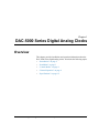
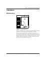
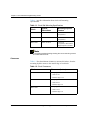
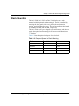
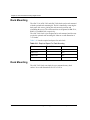
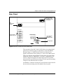
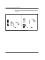
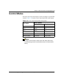
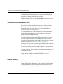
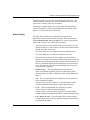
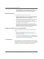
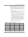
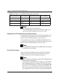
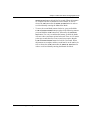
5000 and 5100 Series
Digital Analog Clocks
Installation and Operation Manual
Edition D
5000/5100 MAN
5000/5100Series
Digital Analog Clocks
Installation and Operation Manual
Edition D
August 2006
Trademarks and Copyrights
CCS, CCS CoPilot, CCS Navigator, CCS Pilot, Command Control System,
CineTone, CinePhase, CineSound, DigiBus, DigiPeek, Digital Glue,
DigiWorks, DTV Glue, EventWORKS, EZ HD, Genesis, HDTV Glue,
Image Q, Icon, IconLogo, IconMaster, IconMaster Nav, IconSet, Icon
Station, Inca, Inca Station, InfoCaster, Inscriber, Inscriber CG—FX,
Integrator, LeFont, Leitch, LogoMotion, MediaFile, MIX BOX, NEO, the
NEO design, NEOSCOPE, NewsFlash, Nexio, Opus, Panacea,
PanelMAPPER, Platinum, Portal, PROM-Slide, RouterMAPPER,
RouterWORKS, Signal Quality Manager, SpyderWeb, SuiteView,
TitleMotion, UNIFRAME, Velocity, VelocityHD, VideoCarte, Videotek,
and X75 are trademarks of the Harris Corporation, which may be registered
in the United States, Canada, and/or other countries. All other trademarks
are the property of their respective owners.
Copyright 2006, Harris Corporation. All rights reserved. This publication
supersedes all previous releases. Printed in Canada.
Warranty Information
The Limited Warranty Policy provides a complete description of your
warranty coverage, limitations, and exclusions, as well as procedures
for obtaining warranty service. To view the complete warranty, visit
www.broadcast.harris.com/leitch.
Contents
Preface
Manual Information ............................................................................... iii
Purpose ............................................................................................ iii
Audience ......................................................................................... iii
Revision History ............................................................................. iii
Writing Conventions ....................................................................... iv
Obtaining Documents ..................................................................... iv
Unpacking/Shipping Information ............................................................v
Unpacking a Product .........................................................................v
Product Servicing ..............................................................................v
Returning a Product ..........................................................................v
Restriction on Hazardous Substances (RoHS) Compliance .................. vi
Waste from Electrical and Electronic Equipment (WEEE) Compliance vii
Safety ................................................................................................... viii
Safety Terms and Symbols in this Manual ................................... viii
Chapter 1: DAC-5000 Series Digital Analog Clocks
Overview ..................................................................................................1
Introduction ..............................................................................................2
Installation ................................................................................................3
Wall Mounting ..................................................................................3
Rack Mounting .................................................................................5
Rear Panel .........................................................................................6
Control Modes ..........................................................................................8
Calibration of the Internal Time Base ...............................................8
General Operation ....................................................................................9
Clock Control Modes ........................................................................9
Clock Setting Controls ....................................................................10
5000/5100 Series Digital Analog Clocks Installation and Operation Manual
i
Contents
Specifications ........................................................................................ 12
Electrical ........................................................................................ 12
Primary Drive Inputs ...................................................................... 12
Secondary Time Bases ................................................................... 12
Mechanical ..................................................................................... 13
Chapter 2: ADC-5100 Series Analog Digital Clocks
Overview ............................................................................................... 15
Introduction ........................................................................................... 16
Installation ............................................................................................. 18
Wall Mounting ............................................................................... 18
Rack Mounting ............................................................................... 20
Desk Mounting ............................................................................... 20
Rear Panel ...................................................................................... 21
Control Modes ....................................................................................... 23
General Operation ................................................................................. 24
Clock Control Modes ..................................................................... 24
Clock Setting .................................................................................. 26
Troubleshooting .................................................................................... 32
Hands are Offset ............................................................................. 32
Specifications ........................................................................................ 34
Electrical ........................................................................................ 34
Inputs and Outputs ......................................................................... 34
Time Base ...................................................................................... 34
Controls .......................................................................................... 35
Mechanical ..................................................................................... 35
ii
5000/5100 Series Digital Analog Clocks Installation and Operation Manual
Preface
Manual Information
Purpose
This manual details the features, installation, operation, maintenance,
and specifications for 5000/5100 Series Digital Analog Clocks.
Audience
This manual is written for engineers, technicians, and operators
responsible for installation, setup, maintenance, and/or operation of
5000/5100 Series Digital Analog Clocks.
Revision History
Table P-1. Revision History of Manual
Edition
Date
Comments
C
December 1998 Full release
D
August 2006
Manual reformatted and updated
5000/5100 Series Digital Analog Clocks Installation and Operation Manual
iii
Preface
Writing Conventions
To enhance your understanding, the authors of this manual have
adhered to the following text conventions:
Table P-2. Writing Conventions
Term or
Convention
Description
Bold
Indicates dialog boxes, property sheets, fields, buttons,
check boxes, list boxes, combo boxes, menus,
submenus, windows, lists, and selection names
Italics
Indicates E-mail addresses, the names of books or
publications, and the first instances of new terms and
specialized words that need emphasis
CAPS
Indicates a specific key on the keyboard, such as
ENTER, TAB, CTRL, ALT, or DELETE
Code
Indicates variables or command-line entries, such as a
DOS entry or something you type into a field
>
Indicates the direction of navigation through a hierarchy
of menus and windows
hyperlink
Indicates a jump to another location within the
electronic document or elsewhere
Internet address
Indicates a jump to a Web site or URL
Note
Indicates important information that helps to avoid and
troubleshoot problems
Obtaining Documents
Product support documents can be viewed or downloaded from our
Web site at www.broadcast.harris.com/leitch (go to Support>
Documentation). Alternatively, contact your customer service
representative to request a document.
iv
5000/5100 Series Digital Analog Clocks Installation and Operation Manual
Preface
Unpacking/Shipping Information
Unpacking a Product
This product was carefully inspected, tested, and calibrated before
shipment to ensure years of stable and trouble-free service.
1. Check equipment for any visible damage that may have occurred
during transit.
2. Confirm that you have received all items listed on the packing list.
3. Contact your dealer if any item on the packing list is missing.
4. Contact the carrier if any item is damaged.
5. Remove all packaging material from the product and its associated
components before you install the unit.
Keep at least one set of original packaging, in the event that you need to
return a product for servicing.
Product Servicing
5000/5100 Series Digital Analog Clocks are not designed for field
servicing. All upgrades, modifications, or repairs require you to return
the product to the Customer Service center.
Returning a Product
In the unlikely event that your product fails to operate properly, please
contact Customer Service to obtain a Return Authorization (RA)
number, then send the unit back for servicing.
Keep at least one set of original packaging in the event that a product
needs to be returned for service. If the original package is not available,
you can supply your own packaging as long as it meets the following
criteria:
•
The packaging must be able to withstand the product’s weight.
•
The product must be held rigid within the packaging.
•
There must be at least 2 in. (5 cm) of space between the product and
the container.
•
The corners of the product must be protected.
Ship products back to us for servicing prepaid and, if possible, in the
original packaging material. If the product is still within the warranty
period, we will return the product prepaid after servicing.
5000/5100 Series Digital Analog Clocks Installation and Operation Manual
v
Preface
Restriction on Hazardous Substances (RoHS)
Compliance
Directive 2002/95/EC—commonly known as the European Union (EU)
Restriction on Hazardous Substances (RoHS)—sets limits on the use of
certain substances found in electrical and electronic equipment. The
intent of this legislation is to reduce the amount of hazardous chemicals
that may leach out of landfill sites or otherwise contaminate the
environment during end-of-life recycling. The Directive takes effect on
July 1, 2006, and it refers to the following hazardous substances:
•
Lead (Pb)
•
Mercury (Hg)
•
Cadmium (Cd)
•
Hexavalent Chromium (Cr-V1)
•
Polybrominated Biphenyls (PBB)
•
Polybrominated Diphenyl Ethers (PBDE)
According to this EU Directive, all products sold in the European Union
will be fully RoHS-compliant and “lead-free.” (See our Web site,
www.broadcast.harris.com/leitch, for more information on dates and
deadlines for compliance.) Spare parts supplied for the repair and
upgrade of equipment sold before July 1, 2006 are exempt from the
legislation. Equipment that complies with the EU directive will be
marked with a RoHS-compliant emblem, as shown in Figure P-1.
Figure P-1. RoHS Compliance Emblem
vi
5000/5100 Series Digital Analog Clocks Installation and Operation Manual
Preface
Waste from Electrical and Electronic
Equipment (WEEE) Compliance
The European Union (EU) Directive 2002/96/EC on Waste from
Electrical and Electronic Equipment (WEEE) deals with the collection,
treatment, recovery, and recycling of electrical and electronic waste
products. The objective of the WEEE Directive is to assign the
responsibility for the disposal of associated hazardous waste to either
the producers or users of these products. Effective August 13, 2005,
producers or users will be required to recycle electrical and electronic
equipment at end of its useful life, and may not dispose of the
equipment in landfills or by using other unapproved methods. (Some
EU member states may have different deadlines.)
In accordance with this EU Directive, companies selling electric or
electronic devices in the EU will affix labels indicating that such
products must be properly recycled. (See our Web site,
www.broadcast.harris.com/leitch, for more information on dates and
deadlines for compliance.) Contact your local sales representative for
information on returning these products for recycling. Equipment that
complies with the EU directive will be marked with a WEEE-compliant
emblem, as shown in Figure P-2.
Figure P-2. WEEE Compliance Emblem
5000/5100 Series Digital Analog Clocks Installation and Operation Manual
vii
Preface
Safety
Carefully review all safety precautions to avoid injury and prevent
damage to this product or any products connected to it. If this product is
rack-mountable, it should be mounted in an appropriate rack using the
rack-mounting positions and rear support guides provided. It is
recommended that each frame be connected to a separate electrical
circuit for protection against circuit overloading. If this product relies
on forced air cooling, it is recommended that all obstructions to the air
flow be removed prior to mounting the frame in the rack.
If this product has a provision for external earth grounding, it is
recommended that the frame be grounded to earth via the protective
earth ground on the rear panel.
IMPORTANT! Only qualified personnel should perform service
procedures.
Safety Terms and Symbols in this Manual
WARNING
Statements identifying conditions or
practices that may result in personal injury
or loss of life. High voltage is present.
CAUTION
Statements identifying conditions or
practices that can result in damage to the
equipment or other property.
viii
5000/5100 Series Digital Analog Clocks Installation and Operation Manual
Chapter 1
DAC-5000 Series Digital Analog Clocks
Overview
This chapter provides installation and operation information about the
DAC-5000 Series digital analog clocks. It includes the following topics:
•
“Introduction” on page 2
•
“Installation” on page 3
•
“Control Modes” on page 8
•
“General Operation” on page 9
•
“Specifications” on page 12
5000/5100 Series Digital Analog Clocks Installation and Operation Manual
1
Chapter 1: DAC-5000 Series Digital Analog Clocks
Introduction
The DAC-5000 Series Digital Analog Clocks feature a quiet, digitally
controlled drive mechanism. Each hand is driven independently by a
separate motor and drive train. The exact position of each hand is
microprocessor controlled and virtually error free.
The standard clock face provides two sets of numerals: 1 to12 are black,
and 13 to 24 are red. A clock face with only black numerals from 1 to
12 is optional.
The DAC-5000 Series clocks operate with standard drive signals and
consequently can be easily integrated into new or existing systems.
Selection of the drive signals is made by switches located on the back
panel. The usable drive signals are:
•
Serial Timecode (SMPTE or EBU)
•
12 VDC Impulse Clock
•
Internal Time Base
•
Line Frequency Reference
All clock models accept Serial Timecode are in either the SMPTE or
EBU format.
If reception of the timecode is lost, the error LED located on the clock’s
face will light up and the clock will automatically switch to either the
Internal Time Base or the Line Frequency Reference, as selected on the
back panel switches, without interruption of its operation.
The Internal Time Base is provided by a 4.9 MHz crystal oscillator. The
Line Frequency Reference uses a 50/60 Hz power line. Selection of
either 50 or 60 Hz is made by soldering a jumper on the 5000DL Drive
Logic module.
The following models are available:
2
•
DAC-5016 16 inch illuminated, wall mounting. Rack mounting
kit optional.
•
DAC-5012 12 inch illuminated, wall mounting. Rack mounting
kit optional.
•
DAC-5008
optional.
8 inch illuminated, wall mounting. Rack mounting kit
•
DAC-5006
5 inch non-illuminated, rack mounting.
•
DAC-5005
5 inch non-illuminated, desk top.
5000/5100 Series Digital Analog Clocks Installation and Operation Manual
Chapter 1: DAC-5000 Series Digital Analog Clocks
Installation
Wall Mounting
Figure 1-1. Typical Wall Mount
The DAC-5008, DAC-5012 and DAC-5016 Digital Analog Clocks are
designed for wall mounting. Rack mounting kits are optional.
The rear panels of both the DAC-5012 and DAC-5016 clocks are
provided with four rubber feet and four keyholes while the DAC-5008
has only three keyholes. These are dimensioned for #8 screws. The rear
panel also has a large depression to contain the connecting wires and
allow the clock to be placed close to the wall.
5000/5100 Series Digital Analog Clocks Installation and Operation Manual
3
Chapter 1: DAC-5000 Series Digital Analog Clocks
Table 1-1 provides information about clock wall mounting
specifications
Table 1-1. Clock Wall Mounting Specifications
Clock
Overall
Dimensions
Mounting Keyhole
Centers
DAC-5016
17.45×17.45 in.
16.0×15.5 in.
(4 keyholes)
DAC-5012
13.95×13.95 in.
12.0×10.5 in.
(4 keyholes)
DAC-5008
10.45×10.45 in.
8.0×8.0 in.
(3 keyholes). The bottom
single keyhole is located
Note
A convenient template drawing showing the correct mounting centers
is included with the clock.
Clearances
Table 1-2 lists the minimum clearances, measured in inches, from the
mounting keyhole centers to the outside edge of each clock:
Table 1-2. Clock Clearances
Clock
Clearances (Inches)
DAC-5016
• Top edge 0.8
• Sides 0.725
• Bottom edge 1.275
DAC-5012
• Top edge 1.12
• Sides 0.975
• Bottom edge 2.35
DAC-5008
• Top edge 0.825
• Sides 1.275
• Bottom edge 1.85
4
5000/5100 Series Digital Analog Clocks Installation and Operation Manual
Chapter 1: DAC-5000 Series Digital Analog Clocks
Rack Mounting
The DAC-5008, DAC-5012 and DAC-5016 clocks can be rack
mounted with the optional rack mounting kit. The kit is installed by
removing the back panel side screws, placing the rack mount in
position, and reinstalling the screws. The rack mount kits are designated
as 5008RM, 5012RM, and 5016RM, respectively.
The DAC-5006 clock is pre-designed to be rack mounted, and does not
require the optional rack mounting kit. It has an overall dimension of
7×19 inches.
Table 1-3 lists the required rack space for each clock.
Table 1-3. Required Space For Rack Mounting
Clocks
Rack Units
Inches
DAC-5016
10
17.45
DAC-5012
8
13.95
DAC-5008
6
10.45
DAC-5006
4
7
5000/5100 Series Digital Analog Clocks Installation and Operation Manual
5
Chapter 1: DAC-5000 Series Digital Analog Clocks
Rear Panel
Spring Loaded
“Speaker-Type”
Connectors (red
and black)
AC
Connector
(plug)
115/230 VAC +10%250/60Hz
25VA Max
OPERATION MODE
DAC-5008
DAC-5012
DAC-5016
LINE VOLTAGE
CW
CCW
Push-Buttons:
CW, CCW,
MANUAL SET
MANUAL
SET
115 VAC
230 VAC
3
OPEN
4
5
6
50 HZ
60 HZ
2
Time Code
SMPTE
Internal
Normal
Normal
Step Seconds
LINE FREQUENCY
1
Clock Modes
(factory set)
Multifunctional Pushbuttons
Full Instructions in Manual
Impulse
EBU
Line
Use Offset
Run On Secondary
Sweep Seconds
DIP Switches
Figure 1-2. DAC-5008/5012/5016 Rear Panel
The rear panels of the DAC-5008/5012/5016 have two spring-loaded
speaker-type connectors (one red, one black) to accept the Primary
Reference input (i.e. SMPTE Serial Timecode or Impulse Drive
signals).
A standard AC connector for the power feed of the unit can be found in
the recessed area running across the middle of the rear panel.
6
5000/5100 Series Digital Analog Clocks Installation and Operation Manual
Chapter 1: DAC-5000 Series Digital Analog Clocks
Below this recessed area are the multifunction clock setting buttons and
the six DIP switches (SW1 to SW6), all of which must be set prior to
installation.
LINE VOLTAGE
115 VAC
Run on Secondary
Use Offset
Secondary Ref-Line
Time Code Format-EBU
Not Used
230 VAC
LINE FREQUENCY
1
50 HZ
60 HZ
2
3
4
5
6
OPEN
MANUAL
SET
Normal
Normal
Internal
SMPTE
Primary Ref-Time Code
CCW
MANUAL
SET
LINE VOLTAGE
230 VAC
CCW
LINE FREQUENCY
50 HZ
60 HZ
CW
1
115 VAC
115/230 VAC +20%
50/60Hz
25VA Max
Run on Secondary
Use Offset
Secondary Ref-Line
Time Code Format-EBU
Not Used
CW
2
3
4
5
6
OPEN
Normal
Normal
Internal
SMPTE
Primary Ref-Time Code
115/230 VAC +20%
50/60Hz
25VA Max
Figure 1-3. DAC-5005 (left) and DAC-5006 (right) Rear Panels
5000/5100 Series Digital Analog Clocks Installation and Operation Manual
7
Chapter 1: DAC-5000 Series Digital Analog Clocks
Control Modes
Table 1-4 lists the Clock Control mode DIP switch options.
Table 1-4. Clock Control Mode DIP switch options
Dip Switch
Switch Options
Open
Closed
SW1
Timecode
Impulse
SW2
SMPTE
EBU
SW3
Internal
Line
SW4
Normal
Use offset
SW5
Normal
Run on secondary
SW6 (Secondary)
NA
NA
Calibration of the Internal Time Base
This procedure is used to adjust the frequency of the 4.9152 crystal
oscillator. The accuracy of this adjustment directly affects the accuracy
of the Internal Time Base. The only equipment required is a high
resolution frequency counter.
Connect the frequency counter to the clock test point provided at pin 9
of the CMOS NSC800N Microprocessor IC11. Adjust the 6-25 pF
trimmer capacitor connected to pin 11 of IC11 until the counter
indicates 2.457.600 Hz. It is recommended to use the longest sampling
time possible.
8
5000/5100 Series Digital Analog Clocks Installation and Operation Manual
Chapter 1: DAC-5000 Series Digital Analog Clocks
General Operation
Clock Control Modes
Primary Reference Mode
The Primary Reference Mode provides two options, the Timecode and
the Impulse Clock modes. Selection of either mode is done by switch
SW1.
Timecode Mode
No setting of time is required when the timecode mode is selected.
However, selection of either SMPTE or EBU format should be made by
means of switch SW2.
Upon selecting Timecode mode, the microprocessor will start reading
the code and will light the error LED of the clock face (found under the
6) to indicate that the unit is not yet synchronized with the timecode.
Once the timecode is decoded, the clock hands will move in a clockwise
direction towards the 12:00 position where the three hand detectors are
located. The clock hands will then move to their new position via the
shortest route and the error LED will go off to indicate that the unit is
synchronized with the timecode.
If there is a change in the timecode, the error LED will activate again
while the microprocessor verifies the code to ensure that there is a valid
time change and not a transient condition. This verification requires 30
consecutive full code frames or 1 second for SMPTE format operation,
and 1.2 seconds for EBU format, depending on the selection of switch
SW2. Once the verification is completed and if there is a valid change,
the clock hands will move to the new time position as previously
described and the error LED will go off.
If the timecode is lost due to a mechanical failure such as a
disconnected cable or to a malfunction of the master clock, the error
LED will light up again. The clock, however, will continue to operate
and show accurate time since it will automatically switch to the
secondary time base selected by switch SW3 (either the line frequency,
or the internal crystal oscillator). Once the malfunction is eliminated the
clock will automatically switch back to timecode and re-synchronize to
the incoming timecode, and the error LED will go off.
5000/5100 Series Digital Analog Clocks Installation and Operation Manual
9
Chapter 1: DAC-5000 Series Digital Analog Clocks
Impulse Clock Mode
The DAC-5000 Series clocks will emulate a standard impulse clock.
Like any impulse clock, it must be manually set to the correct time and
will stop if the impulses from the master clock also stop. The unit will
check the polarity of the pulses so that the positive pulses from the red
input connector on the rear panel will move the second hand to an even
number of the clock face (i.e. 2, 4, 6 etc.), while the black input
connector will handle the odd numbers.
This check will only occur after the position of the second hand is
known by the microprocessor. This takes place when the hand passes
the detector located near the 12:00 position.
Correct hand position will be established automatically by the
microprocessor when the clock hands pass their detection positions.
However, to establish the minute hand, the position of the second hand
must be already established. To establish the hour hand, the position of
both the minute and second hands must also be established.
The error LED will not be on when operating as an impulse clock.
Secondary Reference Mode
The DAC-5000 Series clock will run as a standard wall clock with no
exterior Timecode or Impulse drive when selected by the run on
secondary switch SW5. Selection of either Internal reference or Line
frequency is done by switch SW3. Correct hand position is established
in the same manner as for the Impulse Clock. The time must also be set
manually.
The error LED will not be operational when this mode is selected.
Clock Setting Controls
Manual Setting
The clock is manually set by means of three push-buttons located on the
rear panel.
•
10
MANUAL SET Press this button once to select the hour hand,
twice to select the minute hand, three times to select the second
hand, and four times to set the clock. When selected, the hands will
start shaking briskly to visually indicate their status.
5000/5100 Series Digital Analog Clocks Installation and Operation Manual
Chapter 1: DAC-5000 Series Digital Analog Clocks
•
CCW This button moves the selected hand counter-clockwise
one unit. When the time is set, press the MANUAL SET button (a
fourth time) and release it at the exact time that the clock is to be
set. The clock will now return to normal time keeping with the
second hand advancing one second after the MANUAL SET button
is released.
•
CW Press this button to move the selected hand clockwise one
unit. When the time is set, press the MANUAL SET button (a
fourth time) and release it at the exact time that the clock is to be
set. The clock will now return to normal time keeping with the
second hand advancing one second after the MANUAL SET
button is released.
Use Offset
The USE OFFSET function allows the addition of a user programmed
constant offset to the user bits of a standard timecode. Therefore, the
availability of a timecode generator capable of programming the user
bits of the timecode is essential.
This function is generally used when it is desired to simultaneously
provide GMT and local time with two clocks being fed the same
timecode.
The USE OFFSET function is selected by closing the control mode
switch SW4 of the rear panel. Six bits of data are used to specify the
offset. The six bits are divided into two three bit sections. The first three
bits follow the unit minutes at bits 36, 37 and 38 of the timecode. The
second three bits follow the unit hours data at bits 52, 53 and 54. The
minimum offset allowed is 30 minutes. This can be incremented in 30
minute periods until reaching 23 hours and 30 minutes which is the
maximum offset allowed.
5000/5100 Series Digital Analog Clocks Installation and Operation Manual
11
Chapter 1: DAC-5000 Series Digital Analog Clocks
Specifications
Specifications and designs are subject to change without notice.
Electrical
Table 1-5. Electrical
Item
Specification
Electrical voltage
115/230 VAC ±20%
Frequency
50 or 60 Hz, selectable
Power
25 VA max.
Primary Drive Inputs
Table 1-6. Primary Drive Inputs
Input
Item
Specification
Serial timecode
SMPTE/EBU
Impedance
Hi-Z, balanced
Maximum voltage
100 Vp-p
Common mode rejection
55 dB
Level
4 Vp-p ±12 dB
Impedance
Hi-Z, balanced
Maximum voltage
100 Vp-p
Common mode rejection
55 dB
Level
4 Vp-p ±12 dB
Impulse drive
12 VDC±6 dB,
bipolar
Secondary Time Bases
Table 1-7. Secondary Time Bases
12
Item
Specification
Internal
Derived from processor clock 2.4576
MHz, crystal oscillator
Power line
50 or 60 Hz, jumper selectable
5000/5100 Series Digital Analog Clocks Installation and Operation Manual
Chapter 1: DAC-5000 Series Digital Analog Clocks
Mechanical
Table 1-8. Mechanical Specifications
Clock
Item
Specification
DAC-5016
Style
Wall-mount
Face diameter
16 in. (406 mm)
Overall dimensions
17.45×17.45×2.8 in.
(443×443×71 mm)
Weight
9.1 lbs (4.1 kg)
Style
Wall-mount
Face diameter
11.75 in. (298 mm)
Overall dimensions
13.95×13.95×2.8 in.
(354×354×71 mm)
Weight
7.3 lbs (3.3 kg)
Style
Wall-mount
Face diameter
8 in. (203 mm)
Overall dimensions
10.45×10.45×2.8 in. (265×265×71 mm)
Weight
5 lbs (2.3 kg)
Style
Rack-mount
Face diameter
5 in. (127 mm)
Overall dimensions
7×19×2.8 in. (177×482×71 mm)
Weight
4.5 lbs (2 Kg)
Style
Desk-mount
Face diameter
5 in. (127 mm)
Overall dimensions
8.25×6×7.25 in. (209×152×184 mm)
Weight
3.8 lbs (1.75 Kg)
DAC-5012
DAC-5008
DAC-5006
DAC-5005
5000/5100 Series Digital Analog Clocks Installation and Operation Manual
13
Chapter 1: DAC-5000 Series Digital Analog Clocks
14
5000/5100 Series Digital Analog Clocks Installation and Operation Manual
Chapter 2
ADC-5100 Series Analog Digital Clocks
Overview
This chapter provides installation and operation information about the
ADC-5100 Series digital analog clocks. It includes the following topics:
•
“Introduction” on page 16
•
“Installation” on page 18
•
“Control Modes” on page 23
•
“General Operation” on page 24
•
“Troubleshooting” on page 32
•
“Specifications” on page 34
5000/5100 Series Digital Analog Clocks Installation and Operation Manual
15
Chapter 2: ADC-5100 Series Analog Digital Clocks
Introduction
The ADC-5100 Series Analog Digital Clocks are a group of quiet,
digitally controlled, self-setting analog face clocks. These may operate
either stand-alone via power line frequency or internal crystal, or with a
SMPTE or EBU serial timecode input.
When provided with a SMPTE or EBU timecode source, the ADC
Series Clocks are self-setting. If the timecode is valid, the ADC Series
Clocks will advance or reverse their hand positions to the correct time.
In the event of a power failure, the ADC Series Clocks maintain the
correct time internally via a battery-backed timekeeping memory. If
power should be restored without timecode, the ADC Series Clocks will
self-set to the correct time as maintained by the battery backup, and
then continue to operate on internal crystal or power line timebase.
The ADC clocks may operate with either a sweep or step second hand,
and will automatically decode either SMPTE or EBU timecode inputs.
Additionally, the ADC may function as a timecode generator when
operated from its internal crystal. Either SMPTE or EBU timecode may
be generated and used to drive other clocks (in Master Mode).
Note
Internal connector ‘P1’ must be reversed for Master Operation.
The ADC Series clocks are compatible with a user-defined auxiliary
offset when driven from the following clock system drivers;
•
MTG-3901 Master Timing Generator
•
CSD-3901/3902 Master Clock System Driver
•
CSD-5300 Master Clock System Driver.
A local offset can also be provided by electronically re-positioning the
clock hands.
In the event of a timecode input failure, an error LED (located on the
clock face under the 6) will flash at the rate of twice per second. The
ADC clock will then automatically switch to the user-selected
secondary timebase, either power line frequency or internal crystal. The
power line frequency is automatically determined during power-up. The
error LED will illuminate during power-up to indicate 50 Hz power line
frequency detection.
16
5000/5100 Series Digital Analog Clocks Installation and Operation Manual
Chapter 2: ADC-5100 Series Analog Digital Clocks
If timecode operation is not required, the ADC clock may be set to use
the secondary timebase permanently, and the error LED will be
extinguished.
The following models are available:
•
ADC-5116
optional.
16 inch, wall mounting. Rack mounting and light kit
•
ADC-5112
optional.
12 inch, wall mounting. Rack mounting and light kit
•
ADC-5108
optional.
8 inch, wall mounting. Rack mounting and light kit
•
ADC-5106
5 inch, rack mounting. Light optional.
•
ADC-5105
5 inch, desk top mounting. Light optional.
5000/5100 Series Digital Analog Clocks Installation and Operation Manual
17
Chapter 2: ADC-5100 Series Analog Digital Clocks
Installation
Wall Mounting
Figure 2-4. Typical Wall Mounting
The ADC-5108, ADC-5112, and ADC-5116 Analog Digital Clocks are
designed for wall mounting. Rack mounting kits are optional.
The rear panels of both the ADC-5112 and ADC-5116 clocks are
provided with four rubber feet and four keyholes, while the ADC-5108
has only three keyholes. These are dimensioned for #8 screws. The rear
panel of all three clocks is recessed for connectors, and to allow the
clock to be placed close to the wall.
18
5000/5100 Series Digital Analog Clocks Installation and Operation Manual
Chapter 2: ADC-5100 Series Analog Digital Clocks
Table 2-9 provides information about clock wall mounting
specifications
Table 2-9. Clock Wall Mounting Specifications
Clock
Overall
Dimensions
Mounting Keyhole
Centers
ADC-5116
17.5×17.5 in.
16.0×15.5 in.
(4 keyholes)
ADC-5112
14.0×14.0 in.
12.0×10.5 in.
(4 keyholes)
ADC-5108
10.5×10.5 in.
8.0×7.75 in.
(3 keyholes).
The bottom single
keyhole is located 0.35
in. to the right of the
center line.
Note
A convenient template drawing showing the correct mounting centers
is included with the clock.
Clearances
Table 2-10 lists the minimum clearances, measured in inches, from the
mounting keyhole centers to the outside edge of each clock:
Table 2-10. Clock Clearances
Clock
Clearances (Inches)
ADC-5116
• Top edge 0.813
• Sides 0.75
• Bottom edge 1.187
ADC-5112
• Top edge 1.125
• Sides 1.0
• Bottom edge 2.375
ADC-5108
• Top edge 0.875
• Sides 1.250
• Bottom edge 1.875
5000/5100 Series Digital Analog Clocks Installation and Operation Manual
19
Chapter 2: ADC-5100 Series Analog Digital Clocks
Rack Mounting
The ADC-5116, ADC-5112 and ADC-5108 clocks can be rack mounted
with the optional rack mounting kit. The kit is installed by removing the
back panel side screws, placing the rack mount in position, and
reinstalling the screws. The rack mount kits are designated as RM-5116,
RM-5112, and RM-5108, respectively.
The ADC-5106 clock is pre-designed to be rack mounted, and does not
require the optional rack mounting kit. It has an overall dimension of
7×19 inches.
Table 2-11 lists the required rack space for each clock.
Table 2-11. Required Space For Rack Mounting
Clocks
Rack Units
Inches
ADC-5116
10
17.5
ADC-5112
8
14.0
ADC-5108
6
10.5
ADC-5106
4
7
Desk Mounting
The ADC-5105 clock can simply be set or mounted on any desk
surface. Its overall dimensions are 8.25 x 5.85 in.
20
5000/5100 Series Digital Analog Clocks Installation and Operation Manual
Chapter 2: ADC-5100 Series Analog Digital Clocks
Rear Panel
Spring Loaded
“Speaker-Type”
Connectors (red
and black)
AC
Connector
(plug)
OPERATION MODE
SLAVE
MASTER
ADC-5108
Clock Modes
(factory set)
ADC-5108-L
ADC-5112
ADC-5112-L
Multifunctional Pushbuttons
Full Instructions in Manual
CW
ADC-5116
CCW
Push-Buttons:
CW, CCW,
MANUAL SET
MANUAL
SET
ADC-5116-L
Line Voltage
2
3
OPEN
4
5
230VAC
1
6
Time Code
SMPTE
Internal
Normal
Normal
Step Seconds
115VAC
Impulse
EBU
Line
Use Offset
Run On Secondary
Sweep Seconds
DIP Switches
115/230 VAC +10%
50/60Hz
15VA Max
Figure 2-5. ADC-5108/5112/5116 Rear Panel
The rear panels of the ADC-5108/5112/5116 have two spring-loaded
speaker-type connectors (one red, one black) to accept the Primary
Reference input (i.e. SMPTE Serial Timecode or Impulse Drive
signals). Note that the correct polarity (i.e. red-to-red) is not required.
There is an indicator along the left side of the clock rear panel noting
whether the clock is in “MASTER” or “SLAVE” configuration. All
clocks are shipped configured for timecode input (slave) operation,
unless otherwise specified when ordering. The clock type and operating
voltage are also indicated on the rear panel.
A standard AC connector for the power feed of the unit can be found in
the recessed area running across the middle of the rear panel.
5000/5100 Series Digital Analog Clocks Installation and Operation Manual
21
Chapter 2: ADC-5100 Series Analog Digital Clocks
Below this recessed area are the multifunction clock setting buttons and
the six DIP switches (SW1 to SW6), all of which must be set prior to
installation.
OPERATION MODE
SLAVE
MASTER
MANUAL
SET
ADC-5106
Run on Secondary
Use Offset
Secondary Ref-Line
Time Code Format-EBU
Not Used
1
2
3
4
5
6
ADC-5106-L
OPEN
Line Voltage
115VAC
OPERATION MODE
230VAC
SLAVE
MASTER
ADC-5105
MANUAL
SET
ADC-5105-L
Run on Secondary
Use Offset
Secondary Ref-Line
Time Code Format-EBU
Not Used
Step Seconds
Normal
Normal
Internal
SMPTE
Primary Ref-Time Code
CW
1
2
3
4
5
6
OPEN
CCW
Line Voltage
115VAC
230VAC
CCW
Step Seconds
Normal
Normal
Internal
SMPTE
Primary Ref-Time Code
CW
115/230 VAC +10%
50/60Hz
15VA Max
115/230 VAC +10%
50/60Hz
15VA Max
Figure 2-6. ADC-5105 (left) and ADC-5106 (right) Rear Panels
22
5000/5100 Series Digital Analog Clocks Installation and Operation Manual
Chapter 2: ADC-5100 Series Analog Digital Clocks
Control Modes
Selection of the clock control modes is achieved with the rear panel DIP
switches. Table 2-12 lists the Clock Control mode DIP switch options.
Table 2-12. Clock Control Mode DIP switch options
Dip Switch
Switch Options
Open
Closed
SW1
Timecode
Impulse
SW2
SMPTE
EBU
SW3
Internal
Line
SW4
Normal
Use offset
SW5
Normal
Run on secondary
SW6 (Secondary)
Step seconds
Sweep seconds
Note
Changes to the DIP Switch settings (other than SW3) made during
clock self-setting will NOT be recognized until the clock has finished
setting.
5000/5100 Series Digital Analog Clocks Installation and Operation Manual
23
Chapter 2: ADC-5100 Series Analog Digital Clocks
General Operation
Clock Control Modes
Primary Reference (timecode) Mode
No setting of time is required when input timecode is provided to the
ADC Series clock. Once valid timecode is detected, either SMPTE or
EBU, the clock will begin to self-set. The self-setting procedure moves
the hands at a rapid rate in either the clockwise or counter-clockwise
direction until the correct position is obtained. If the hands and the
correct time are the maximum distance apart (6 hours), the self-setting
process may require up to 15 minutes to complete.
Once the clock hands match the correct time, as indicated by the input
timecode, the error LED on the clock face will extinguish to indicate
that the clock is synchronized with the timecode.
The clock may require up to 2 additional minutes of normal operation
(following self-set) for the second hand to completely re-synchronize.
This is due to accumulated gear slippage during counter-clockwise
movements.
If there is a failure of the input timecode, the clock will switch to the
Secondary Reference as selected by DIP switch SW4 on the rear panel.
Either the clock’s own internal crystal or the power line frequency may
be selected as the secondary reference. Both will provide the clock with
a timebase during the absence of input timecode. (Note that either a 50
Hz or 60 Hz power line frequency is suitable for the timebase, since the
clock automatically selects the correct frequency available.)
To signal the failure of the input timecode, the error LED on the clock
face will flash at a rate of twice per second. When correct timecode is
re-established, the clock will again self-set to the new time, and the
error LED will extinguish.
Similarly, if there is an error in the input timecode, the clock will
automatically switch to the secondary reference, and the error LED will
flash.
Note
Impulse input is not currently recognized by the ADC-5100 Series
clocks.
24
5000/5100 Series Digital Analog Clocks Installation and Operation Manual
Chapter 2: ADC-5100 Series Analog Digital Clocks
Secondary Reference Mode
The ADC-5100 Series clocks will run as standard wall clocks when no
input timecode is provided. Rear panel DIP switch SW4 selects the
timebase to be used, either the clock’s internal crystal, or the power line
frequency (50/60Hz).
Rear panel DIP switch SW2 should be switched to the RUN ON
SECONDARY position when the clock is used in this mode. When in
this position, the error LED on the clock face will extinguish. Note that
the clock will still function without selecting RUN ON SECONDARY.
However, the error LED will flash at the rate of twice per second to
indicate the absence of input timecode.
When operating in this mode, the time must be set manually using the
rear panel set switches, MANUAL SET, CW, and CCW. Once set,
however, the correct time is maintained even in the event of a power
failure. Upon the return of external power, the clock will automatically
self-set to the correct time. The internal battery-backed timekeeping
function will maintain time for up to two years in the absence of
external power.
Auxiliary Offset
DIP switch SW3 allows access to a user-programmed auxiliary offset
from the input timecode’s user bits. The timecode source, however,
must have the ability to generate the correct information in the user bits.
The MTG-3901, CSD-3901/3902, and CSD-5300 Clock System
Drivers are real time timecode sources which can program such an
offset into the timecode’s user bits. The offset is programmed in 30
minute intervals up to 23 hours and 30 minutes, using 6 bits of the
timecode’s user bit space.
The offset is encoded using timecode bits 36, 37, 38, 52, 53, and 54. Bit
36 is the least significant bit (LSB), while bit 54 is the most significant
bit (MSB).
When DIP switch SW3 on the ADC-5100 Series clock is in the USE
OFFSET position, the auxiliary offset found in the input timecode’s
user bits is added to the input timecode. The clock hands then display
the total. If no input timecode is available, then DIP switch SW3 has no
effect. If the user bits are incorrectly programmed, then the offset is
disregarded.
5000/5100 Series Digital Analog Clocks Installation and Operation Manual
25
Chapter 2: ADC-5100 Series Analog Digital Clocks
Local offsets (hand position offsets) are still in effect while using the
auxiliary offset. The hand positioning local offsets are totally
transparent to the input timecode’s user bit offset.
If input timecode is removed while USE OFFSET is selected, the clock
will retain the time with the offset added, not the original time.
Timecode Generator Mode (Master Clock)
The ADC Series Clocks can also function as real time timecode
generators, essentially operating as master clocks. In this mode, the
clock will be accurate to within + 4 seconds per month. (The
MTG-3901, CSD-3901/3902, and CSD-5300 master clocks are
accurate to within + 1 second per year.)
To configure the ADC as a timecode generator, an internal connector
must be transposed so that the rear panel speaker-type connectors
become the timecode output terminals.
To do this, remove the 10 screws along the outside edge of the clock.
Carefully lift the rear panel from the chassis taking care not to disturb
the cables connected to the motor assembly. (If the cables become
disconnected, the time shown on the hands may become offset from the
real time, in which case, see “Clock Setting” on page 26.)
Follow the two wires from the speaker-type terminals to their connector
on the PC board. The connector, attached at point P1, must be removed
and reversed. Normally, the wires on the connector are located near the
corner of the board at pin 1. Reversing this will relocate the wires on the
connector to pin 10. When completed, return the rear panel chassis and
re-fasten the 10 screws.
After completing this process, the rear speaker-type connectors will
output real time timecode when DIP switch SW4 is set to the
INTERNAL position.
To set the time, see “Clock Setting”.
Clock Setting
When shipped from the factory, the hands are set to 12:00. The clock’s
internal microprocessor has been re-set to memorize this hand position,
and the internal battery has been electronically disabled to preserve
battery life during storage and shipping.
26
5000/5100 Series Digital Analog Clocks Installation and Operation Manual
Chapter 2: ADC-5100 Series Analog Digital Clocks
When first powered up, the clock will start from 12:00:00. Or, if the
external timecode is present, the clock will automatically reset to the
correct time. This may take up to 15 minutes.
The battery is enabled when power is first applied. Henceforth, the
clock will continue to retain time information for the lifetime of the
battery, even if the power is disconnected.
Manual Setting
The ADC Series clocks may be manually set using the three
push-button switches located on the rear panel. These push-buttons,
labelled MANUAL SET, CW, and CCW may be used to reposition the
hands of the clock for any of the following reasons:
•
The clock will be used as a Stand Alone Clock, locked to its own
internal crystal or AC line frequency. In this case the hands must be
initially set to the correct time.
•
The clock will be used as a master timecode generating clock.
•
The clock hands must be offset for a different time zone.
•
The offset must be removed. (For example, an offset of hours,
minutes, or seconds may have been inadvertently applied if the rear
buttons were actuated without following the correct procedure. In
this case, the hands and the internal microprocessor must both be
set to the same time. The clock will then display the correct time
when timecode is applied).
•
MANUAL SET This rear panel button stops hands and
enters/exits Manual Set Mode. (LED is on continuously when
entering Manual Set Mode, LED flashes when exiting Manual Set
Mode.)
•
CW
This rear panel button moves hands one second clockwise
while in Manual Set Mode.
Advances time one hour if held for 10 seconds during normal
operation (non-Manual Set Mode), without timecode input.
•
CCW This rear panel button moves hands 50 seconds
counter-clockwise while in Manual Set Mode.
Changes time by minus one hour if held for 10 seconds during
normal operation (non-Manual Set Mode), without timecode input.
•
CW + MANUAL SET Pressed together, these buttons advance
second hand position for precise tracking during normal operation
(non-Manual Set Mode).
5000/5100 Series Digital Analog Clocks Installation and Operation Manual
27
Chapter 2: ADC-5100 Series Analog Digital Clocks
•
CCW + MANUAL SET
Pressed together, these buttons move
second hand position in counter-clockwise direction for precise
tracking during normal operation (non-Manual Set Mode).
Repositioning the Hands
To reposition the clock hands, follow these steps:
1. Enter the Manual Set Mode by pressing and holding the MANUAL
SET button until the hands come to a complete stop and the error
LED at the bottom of the clock face is illuminated.
2. The CW button advances the hands clockwise by one second each
time it is pressed. If the CW button is held down, the hands
accelerate until full speed is reached (after about 30 seconds). To
stop the hands, re-press the CW button.
3. The CCW button causes the hands to move counter-clockwise.
When pressed once, the hands move backwards 50 seconds. If the
CCW button is held down, the hands accelerate until full speed is
reached. To stop the hands, re-press the CCW button.
Setting the Time in Master Clock or Stand Alone Modes
To set the time in Master Clock or Stand Alone modes, follow these
steps:
1. Follow the steps described in “Repositioning the Hands”.
2. Stop the hands a little after the real time and wait for the precise
moment to start the clock.
3. Press and hold the MANUAL SET button. Release MANUAL SET
one second before the correct time to ensure proper synchronization
with the time of day. The clock will start normally.
Local Time Offsets
The clock hands may be electronically repositioned to provide a local
offset from the input timecode. This is particularly useful for displaying
multiple time zones from the same timecode source. There are a number
of methods to achieve this and the simplest is described below.
28
5000/5100 Series Digital Analog Clocks Installation and Operation Manual
Chapter 2: ADC-5100 Series Analog Digital Clocks
This method assumes that the local time reference is 12:00:00. The
hands are manually set to the required offset time (according to
Table 2-13 on page 29) and the microprocessor is then reset. This tells
the microprocessor that the hands are at the 12:00 position, whereas in
fact they are set to the offset time. When timecode is applied, the clock
will set itself to the correct offset time. To set an offset, follow these
steps:
1. Disconnect the timecode input.
2. Enter the Manual Set Mode by pressing and holding the MANUAL
SET button until the hands come to a complete stop and the error
LED at the bottom of the clock face is illuminated.
3. Set the hands to the offset time using the CW and CCW buttons as
described in “Repositioning the Hands” on page 28. (For example,
to apply a + 4 hour offset, set the hands to 4:00. If the hands are a
long way off, the process may take up to 15 minutes. A short cut
method is described in “Hands are Offset” on page 32.)
4. Once the hands are positioned at the appropriate time, press and
hold the MANUAL SET button until the error LED flashes. While
still holding the MANUAL SET button, press and hold the CCW
button to reset the microprocessor. Once the LED extinguishes,
release the CCW button and then the MANUAL SET button.
5. Re-connect the timecode. The hands should move to the correct
offset time.
Table 2-13 lists local offset programming settings:
Table 2-13. Table 3.1 Local Offset Programming
Offset Desired (hrs) Move Hands To Offset Desired (hrs) Move Hands To
None
12:00:00
+1/2
12:30:00
+1
1:00:00
+1 1/2
1:30:00
+2
2:00:00
+2 1/2
2:30:00
+3
3:00:00
+3 1/2
3:30:00
+4
4:00:00
+4 1/2
4:30:00
+5
5:00:00
+5 1/2
5:30:00
+6
6:00:00
+6 1/2 or -5 1/2
6:30:00
-5
7:00:00
-4 1/2
7:30:00
5000/5100 Series Digital Analog Clocks Installation and Operation Manual
29
Chapter 2: ADC-5100 Series Analog Digital Clocks
Table 2-13. Table 3.1 Local Offset Programming (Continued)
Offset Desired (hrs) Move Hands To Offset Desired (hrs) Move Hands To
-4
8:00:00
-3 1/2
8:30:00
-3
9:00:00
-2 1/2
9:30:00
-2
10:00:00
-1 1/2
10:30:00
-1
11:00:00
-1/2
11:30:00
Note
The offset range is only ±6 hours due to the
12-hour representation of 24-hour time. For example, offsets of -8 or
+16 hours can both be represented by a move of +4 hours.
Daylight Saving Time Adjustment (Free Running Clocks)
To advance the time by one hour, press and hold the CW button for 10
seconds. Release the CW button when the clock hands begin to move
rapidly. The clock will automatically set to the new time.
To revert the time by one hour, press and hold the CCW button for 10
seconds. Release the CCW button when the block hands begin to move
rapidly. The clock will automatically set to the new time.
Note
When operating from external timecode, daylight saving time is applied
to the master clock, not the ADC.
Second Hand Tracking
If the second hand is not falling on the second marks, the following
calibration procedure should be used while the clock is operating
normally. (Be careful not to enter the Manual Set Mode).
Note
Before moving the seconds hands, place the hands in Step Mode using
DIP switch SW1 (closed position).
•
30
To advance the second hand clockwise slightly, press and hold the
CW and MANUAL SET buttons together in the following manner:
press and hold the CW button first, followed by the MANUAL SET
button. For every second that the buttons are held, the hands will
move three extra motor points forward. There are 150 motor points
per second; therefore a one second error requires that the CW and
5000/5100 Series Digital Analog Clocks Installation and Operation Manual
Chapter 2: ADC-5100 Series Analog Digital Clocks
MANUAL SET buttons be held for 50 seconds. When adjustments
are complete and the second hand is on the marker, be sure to
release the CW button after the MANUAL SET button in order to
avoid accidentally entering the Manual Set Mode.
•
To move the second hand counter-clockwise, press and hold the
CCW and MANUAL SET buttons together in the following manner:
press and hold the CCW button first, followed by the MANUAL
SET button. For every second that the buttons are held, the hands
will move three extra motor points backward. There are 150 motor
points per second; therefore a one second error requires that the
CCW and MANUAL SET buttons be held for 50 seconds. When
adjustments are complete and the second hand is on the marker, be
sure to release the CCW button after the MANUAL SET button in
order to avoid accidentally entering the Manual Set Mode.
•
5000/5100 Series Digital Analog Clocks Installation and Operation Manual
31
Chapter 2: ADC-5100 Series Analog Digital Clocks
Troubleshooting
Hands are Offset
Sometimes the hands are offset by any number of hours, minutes, or
seconds. This generally occurs when the microprocessor loses track of
where the clock hands are positioned. This problem may occur if the
rear push buttons have been pressed in the wrong sequence.
The hands can be re-aligned (see t“Repositioning the Hands” on
page 28). This involves setting the hands to 12:00:00, which may take
up to 15 minutes. A short cut method is provided below.
Note
You cannot use the short cut method for the
24-hour model ADC-5124.
In the shortcut method, the hands are re-positioned to the top of the
closest hour and then the microprocessor is advised of the new hand
position. To re-calibrate the hands using this method follow these steps:
1. Disconnect the timecode. The front LED will flash twice per
second.
2. Press and hold the MANUAL SET button until the LED stays
illuminated.
3. Using the CW and/or CCW buttons (as described in the section
“Repositioning the Hands” on page 28), position the hands to the
top of the nearest hour.
4. Press and hold MANUAL SET. The error LED will start to flash.
5. While holding MANUAL SET, press and hold the CCW button until
the error LED extinguishes.
6. While continuing to hold the MANUAL SET and CCW buttons,
momentarily press the CW button once for every hour indicated on
the hour hand. For example, if the hands are set to 7:00, press the
CW button seven times. The LED will flash once every time the
CW button is pressed. Doing this will tell the microprocessor what
time the hands are showing. To apply offset times, add or subtract
the number of hours offset to the number of times the CW button is
pressed. For example, for -3 hours offset, press the CW button 4
times (7 - 3). In case of difficulties, please see t“Local Time
Offsets” on page 28.
32
5000/5100 Series Digital Analog Clocks Installation and Operation Manual
Chapter 2: ADC-5100 Series Analog Digital Clocks
7. Release the CCW button, and then release the MANUAL SET
button.
8. Re-connect timecode.
5000/5100 Series Digital Analog Clocks Installation and Operation Manual
33
Chapter 2: ADC-5100 Series Analog Digital Clocks
Specifications
Specifications and designs are subject to change without notice.
Electrical
Table 2-14. Electrical
Item
Specification
Electrical voltage
115/230 VAC ±20%, selectable
Frequency
50 or 60 Hz, automatic selection
Inputs and Outputs
Table 2-15. Inputs
Item
Specification
Serial timecode
SMPTE/EBU
Impedance
Hi-Z, balanced
Level
4 Vp-p ±8 dB
Table 2-16. Outputs
Item
Specification
Serial timecode
SMPTE/EBU non-drop frame
Impedance
Lo-Z, balanced
Level
+10 dB nominal unloaded -3dB
into 180 Ohms
Time Base
Table 2-17. Time Base
34
Item
Specification
Timecode
SMPTE/EBU, automatic selection
Internal
Crystal, ± 4 sec/month, 0°—50°C
Power line
50 or 60 Hz, automatic selection
Battery backup
Crystal, ± 10 sec/month, 0°—50°C
5000/5100 Series Digital Analog Clocks Installation and Operation Manual
Chapter 2: ADC-5100 Series Analog Digital Clocks
Controls
Table 2-18. Controls
Item
Specification
Output timecode format
SMPTE/EBU
Secondary reference
Internal or power line
Second hand movement
Step or continuous sweep
Aux. offset
Requires one of the following system
clock drivers:
• MTG-3901
• CSD-3901/3902
• CSD-5300
Mechanical
Table 2-19. Mechanical Specifications
Clock
Item
Specification
ADC-5116
Style
Wall-mount
Face diameter
16 in. (406 mm)
Overall dimensions
17.5×17.5×3.375 in. (445×445×86 mm)
Style
Wall-mount
Face diameter
11.5 in. (292 mm)
Overall dimensions
14.0×14.0×3.375 in. (356×356×86 mm)
Style
Wall-mount
Face diameter
8 in. (203 mm)
Overall dimensions
10.5×10.5×3.375 in. (267×267×71 mm)
Style
Rack-mount
Face diameter
5.4 in. (137 mm)
Overall dimensions
8.25×19×6.6 in. (178×483×168 mm)
Style
Desk-mount
Face diameter
5 in. (127 mm)
Overall dimensions
8.25×5.85×7.25 in. (209×145×184 mm)
ADC-5112
ADC-5108
ADC-5106
ADC-5105
5000/5100 Series Digital Analog Clocks Installation and Operation Manual
35
Chapter 2: ADC-5100 Series Analog Digital Clocks
36
5000/5100 Series Digital Analog Clocks Installation and Operation Manual
A brand of Harris Corporation
Harris and Leitch are registered trademarks of Harris Corporation. Trademarks and tradenames are the property of their respective companies.
Broadcast Communications Division
4393 Digital Way | Mason, OH USA 45040 | Tel: 1 (513) 459 3400
www.broadcast.harris.com
©2006 Harris Corporation