1
9000XDrive User Manual
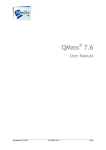
What is 9000XDrive?
9000XDrive is basically a commissioning tool for setting the parameters of an application running
in the frequency converter. You can change the parameter settings in the frequency converter via
a PC instead of a panel. You can even change the parameter settings in offline mode and save
the settings to file for later downloading to frequency converter.
But 9000XDrive is also more. You can print the parameter settings to paper for archiving
purposes.
You can monitor up to eight signals simultaneously in graphical format and set triggers which
allow you to see what happened in the frequency converter when the trigger fired.
You can control the motor by setting the references and commanding the motor to start or stop or
change direction by clicking buttons in the Operating window.
The diagnostic page allows you to see the fault history as well as active faults.
Offline mode
In offline mode you can change the application’s parameters without connection to the frequency
converter. You just select the application (File|New) from application files in your PC, set the
parameters, and finally save the settings to a parameter file. Later when you are connected to a
frequency converter, you can load the parameters from that file and download them to the
frequency converter.
Every time you open a parameter file, the mode is automatically set to offline mode. So if you are
in online mode and then open a parameter file, the mode is set to offline and all the other
windows requiring online mode are closed automatically.
When you download the parameters, the mode is automatically set to online mode so that you
can continue your commissioning.
Online mode
In online mode you are in direct communication with the converter. If you change a parameter’s
value, it is written directly to the converter. Online mode also means that you can monitor the
signals in the frequency converter. The 9000XDrive program is automatically set to online mode
when you upload parameters, download a parameter file, or go to a page that requires online
mode.
1
9000XDrive User Manual
Upload
Upload means the uploading of the parameters from the frequency converter. After uploading you
will see the current parameter settings in the frequency converter and 9000XDrive is put in online
mode so that you can make immediate changes to parameters.
When you upload the parameters, the application and its version and revision are checked from
the frequency converter and 9000XDrive tries to find a compatible application database in the
hard drive. If you have many such databases in your hard drive, 9000XDrive will show you a list
of these databases and lets you to choose from them. If 9000XDrive is unable to find the
application database from the Applications directory, it lets you to find the database yourself. You
can set 9000XDrive to always choose the first compatible database it finds from your hard drive
by checking the ‘Always let the program to use the first compatible database and never show the
compatible database list’ checkbox.
You can also let 9000XDrive generate the application database automatically if it is not found on
your hard drive.
Open the Options dialog from Tools menu and check the ‘If a compatible VCN is not found, start
generating automatically’ checkbox.
You can do an upload in several different ways:
1. Press the Upload button in the toolbar.
2. Change the mode to Online. This will do the upload automatically.
3. Press the Parameter Window button in the toolbar. This will do the upload automatically.
4. Choose Upload from the Drive menu.
2
9000XDrive User Manual
Download
Download means downloading all of the parameters to the frequency converter. When you are in
online mode and change a parameter’s value and press enter, the value is written to frequency
converter right away. But if you are in offline mode, the parameter values are not written to
frequency converter until you select Download. Parameters are downloaded in the order of the
panel tree.
You can download the parameters in several different ways:
1. Press the Download button in the toolbar.
2. Choose Download from the Drive menu.
3
9000XDrive User Manual
Creating a parameter file in offline mode
If you are not connected to any frequency converter you can still create a parameter file by
selecting that application in offline mode. Of course you must have that application database in
your computer.
You can save the parameter file to your computer and later download the parameters to a
frequency converter.
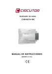
First select New from File menu. A dialog will appear where you can select the right application:
1. File box shows the vcn packets in a selected directory.
2. Application box shows all the applications in a selected vcn packet.
3. Application Info table shows information of the selected application.
4
9000XDrive User Manual
Vcn packets
Vcn packets are used by 9000XDrive and 9000XLoad programs. These packets can contain
various kinds of information. Basically they are simply compressed files that contain many files.
Vcn packets have a type that tells 9000XDrive and 9000XLoad what they contain. A Vcn packet
may be a packet that contains a firmware file to load with 9000XLoad program as well as all the
databases of the applications that this firmware contains. A Vcn packet may be a packet that
contains one or more application files and their databases or it can be a packet that contains an
option card program.
9000XDrive will show you only Vcn packets that contain application databases. For example
option card Vcn does not contain any applications so it doesn’t contain any application databases
either.
Vcn packets are automatically generated during the application development process by the
application compiler. There is also a possibility to generate the database by reading it from a
frequency converter and saving it to a hard-drive. This method reads only the information that the
9000XDrive needs. These Vcn databases can’t be used in application development or with
9000XLoad.
Generating an Application Database
If you don’t have a compatible application database, you are not able to use 9000XDrive with
your frequency converter. The 9000XDrive program however has a feature that allows you to
generate the needed database by reading it from a frequency converter.
When you generate an application database this way, the resulted Vcn file always contains only
the application that was active in the frequency converter when the generating was started.
All the application databases are generated to a directory called ‘Generated’ under the
‘Applications’ directory.
Select ‘Tools|Generate Application VCN’ from menu. You will be prompted for a name and
directory of an application database to be generated. 9000XDrive will suggest the ‘Generated’
directory and the suggested name will be a combination of the application ID, application revision
and the parameter revision of the application followed by the string ‘gen’ to indicate that the file is
a generated file (e.g. NXFIFF01_2_2_gen.Vcn).
The time required for generating an application database depends on the size of the application.
On average it will take a few minutes. Remember that you have to do the application generation
only once. The generated database will be in your hard-disk and the 9000XDrive will use it from
now on.
5
9000XDrive User Manual
Expander board parameters in 9000XDrive
Offline mode
If you want to make a parameter file that contains expander board parameters in the offline mode,
you must specify which expander boards are placed in which slots. You can do this by doubleclicking the slot and selecting a board from a dropdown combo boxes in the ‘Expander board
selection’ window. Note that the same definition window opens from all of the slots, so you can
specify all the slots at the same time.
The combo boxes will show only those expander boards that are possible to insert into the slot.
After you have selected the board, you can see the parameters in 9000XDrive’s Parameters
window.
When you download the parameter file into frequency converter, the expander board parameters
are downloaded to frequency converter only if the board in 9000XDrive’s slot is the same type
and in the same slot as in the frequency converter.
Online mode
In online mode you can automatically see the expander boards and their parameters that are
currently inserted in the frequency converter’s slots.
System parameters in 9000XDrive
The system parameter menu in the frequency converter contains many parameters that are
available in 9000XDrive’s other menus (such as Application selection in Drive|Application) and
variables (such as Internal brake resistor in Drive Info window) and also parameters that make no
sense in 9000XDrive (such as Load up to keypad), so the system menu in 9000XDrive differs a
from the system menu in the frequency converter.
The system menu can be found in the menu tree in Parameter window. The system parameters
will have the same menu index as in panel, but some of the parameters are just not visible.
Offline mode
If you open an ‘old’ parameter file (that does not contain the system parameters), the 9000XDrive
will show a message to notify you that the system menu in 9000XDrive will contain default values.
If you just open an old parameter file and then download it to frequency converter, the system
parameters could contain values that you don’t want to download. You can of course change the
system parameter values after opening the parameter file and after that do the download. Also
when the parameter file is saved again with new 9000XDrive, the parameter file will contain the
system parameters.
If you open a new parameter file (with system parameters), the system menu will show the saved
parameter values. If you start to make a completely new parameter file by choosing an
application from the File|New menu, 9000XDrive will always show the system menu.
Online mode
In online mode you can see the system menu in 9000XDrive if the system software in frequency
converter supports the system menu. The system menu support was added to the system
software in October 2002, so the new system software packages will contain the support.
6
9000XDrive User Manual
Service Info
In trouble situations you can print some useful information of your frequency converter by
selecting File|Service Info... This menu item will read the parameter values from the frequency
converter together with Drive Info and Fault Info, and show them in a window. You can then print
the contents of this window, or save it to a file.
Trend Recorder
Trend Recorder is used together with the Monitor window. Whenever the Trend Recorder menu is
clicked in the Tools menu, the Monitor window will also open. The Trend Recorder saves the
monitored data to a file at the same time as it is updated to your PC screen. The Monitor window
itself has a very limited buffer, so you cannot scroll back and forth in data much. When the Trend
Recorder is used, only the disk space is a limiting factor. When a recorded file is opened, the data
is shown in the Monitor window, one page at a time. You can scroll through the file using the
scroll controls in the Trend Recorder window.
1.
You can select to record a trend for a pre-defined time, or you can stop the recording
manually by pressing the Stop Recording button. If you select the ‘Stop recording manually’
option, the recording is stopped anyway when there is less than 10MB (or whatever you have
specified in the Options dialog) disk space left. The maximum pre-defined time that you can
record is 23 hours, 59 minutes and 59 seconds.
2.
When you are ready to record, press the Start Recording button. A dialog will open that
asks a file name for your recording. The recording starts immediately after you press the Save
button in the dialog.
3.
Press the Open Recorded File button to open existing trend files.
7
9000XDrive User Manual
4.
‘Skip’ text box defines how the recorded file is read back to PC. If the value is 0, all the
data is read, if it is 1, every second measurement is read, if it is 2, every third measurement is
read and so on. If the recording is long, you can “compress” it into screen by skipping some
measurements. Note that aliasing will happen is you skip the measurements.
5.
Use this scroll bar to navigate through the recorded file. One click on the arrows will
move one page forward or backward in the file. If you need to move less, you can use the ‘Fine’
scroll bar. It will move the graphics within one page.
6.
You can print a page or a range of pages of the recorded data.
Datalogger
The Datalogger window can be used to set and read datalogger files from the frequency
converter.
First you set signals that you are interested in and also one signal that is used as a trigger. The
frequency converter will then poll the trigger signal and see when the conditions for the trigger are
met. After the datalogger has been set, the frequency converter starts to log the signals. This
logging can be made at a very high speed (1ms interval) because all the logging is done in the
frequency converter itself.
When the trigger signal triggers, the datalogging is stopped and depending on the PreTrigg
setting the buffer now contains data from the trigging point and some time before and after it.
After the datalogger buffer is full, you can read it to the PC and see the signals in graphical
format.
You can close the Datalogger window after you have set your datalogger conditions to the
frequency converter. You can see the status of the datalogger in 9000XDrive’s status row. It will
show one of the following texts: Idle, Waiting Trigger, Post Trigging, Trigged.
The datalogger data in the frequency converter stays there until you remove power. So you can
read the existing datalogger data at any time. When the data is read from the frequency
converter, it is always saved to a file in your PC. You can open and view these files also at any
time.
After loading a system program to a frequency converter, the system software puts eight
predefined signals to datalogger by default. These variables are: IU_CurrentMotor_fws16,
IV_CurrentMotor_fws16, IW_CurrentMotor_fws16, DCVoltageUnFiltered_fwu16, FreqOut_fws16,
MotorRegulatorStatus_fwu16, MotorCurrentUnFiltered_fwu16, MotorTorqUnfiltered_fws16. The
Trigger signal is MCStatus. (Note that these depend on the system program.)
So there is always a default datalogger in the frequency converter unless you set your own
datalogger.
Note! The datalogger buffer is not cleared when new a datalogger is set. If the new datalogger
triggers before about 5 seconds has elapsed since the datalogger has been set, there might be
old data in the buffer! The data after the trigger point is always correct, but the data before trigger
point might be wrong.
8
9000XDrive User Manual
Datalogger Window
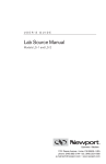
1. Source combo box.
This combo box categorizes the signal names in the Signal combo box. If you select Keypad, you
will see all the Parameters and Values of the application. If you select Firmware, you will see all
the variables of the firmware. If you select Application, you will see all the application variables.
2. Signal combo box.
This combo box lists all the variables read from the application or FCR file.
3. Data type textbox.
This textbox shows the data type of the signal you have chosen from the Signal combo box.
9
9000XDrive User Manual
4. Trigger settings.
The trigger can be set to occur either whenever a fault occurs or when the user defined trigger
conditions occur. In newer drives, it can also be set to trigger on either condition.
Depending on the system software version in the drive, you will have either two option buttons or
two checkboxes (on drives manufactured after April 2005). With newer drives, you can set the
datalogger to trigger on either the fault or the user defined condition by selecting both
checkboxes. On older drives you can only select one or the other of the two methods using the
option buttons.
5. Force Trig
You can force the trigger manually by clicking the Force Trig button.
6. You can select the trigger signal in the same way as the datalogger signals.
7. Bit Mask, Level, Rising and Falling.
If you select the Bit Mask option button, you must enter a bit mask into the text box below the
option button. The bit mask is a decimal number and all bits in the bit mask must be ‘1’ until the
trigger occurs. If you enter an 8, it means that bit 4 must be ‘1’ for the datalogger to trigger.
If you select the Level option button, you muster enter a level for the trigger signal to cause the
datalogger to trigger. The Rising and Falling option buttons are used to define whether the trigger
should occur on the rising or falling edge of the signal. If Bit Massk is selected and the mask has
only one bit set, the Rising and Falling option buttons define if the triggering occurs when the bit
is set or unset. If Level is selected, the datalogger triggers when the signal level goes above or
below the level.
Example:
Set MC_Status as the Trigger signal and select Bit Mask. Set Bit Mask number to 8. This means
the bit number 4 in the MC_Status signal.
Bit Value: ………. 256 128 64 32 16 8 4 2 1
MC_Status(word): 0
0 0 0 0 1 0 0 0
Bit Number……… 9
8 7 6 5 4 3 2 1
8. Pre Trigg % and Sample Period.
The Pre Trig setting indicates how much of the available datalogger space will be used for the
data before the trigger event. If Pre Trigg% is set to 50%, half of the data stored in the datalogger
will be from the time just preceding the trigger and half will be from the time after the trigger point.
The Sample Period setting determines the sampling period. The frequency converter samples
data at a 1ms sampling period. If the datalogger Sampling Period is set to 3ms, this means that
every third sample in the frequency converter will be written to the datalogger buffer. The buffer
size is not fixed. It depends on the free RAM memory in the frequency converter.
9. Single and Continuous.
If the Single option button is selected, you have to manually restart the datalogger back every
time a trigging has occurred.
If the Continuous option button is selected, the datalogger automatically restarts after a trigger
has occurred.
10
9000XDrive User Manual
10. Datalogger buffers
The latest trigged datalogger data is always in RAM memory ('Current' checkbox) of the
frequency converter. The data is then copied into FLASH memory ('History') so that the data is
not lost if frequency converter is switched off. Every time the datalogger triggers, the latest data is
put into slot 1 and the rest are moved up. Slot 1 goes to slot 2, slot 2 goes to slot 3, slot 3 goes to
slot 4, and slot 4 is lost.
Note that these option buttons are visible only if the system software in drive is new enough (later
than April 2005), and if "Advanced Datalogger" checkbox has been checked in
Options|Datalogger.
11. Load from Target.
When the datalogger has trigged you will see text ‘Trigged’ in the 9000XDrive’s status row. You
can then upload that data to your PC. Pressing this button will first open a dialog where you must
give a file name where the data will be saved. After the data has been read to a file, it is opened
into the Datalogger window.
12. Set New.
After you have set the signals and the trigger, you can press the ‘Set New’ button to write the
settings to the frequency converter. The text in the status row will change to ‘Waiting Trigger…’.
Setting a datalogger
After you have set the signals and the trigger, you can press the Set button to write the settings to
the frequency converter. The text in the status row will change to Waiting Trigger….
If you wish, you can now close the Datalogger window, because the data logging and trigging
happens in the frequency converter. The status (Idle, Waiting Trigger…, Post Trigging…, Trigged
is updated on the status bar of the 9000XDrive tool.
Reading the datalogger data from the frequency converter.
When the datalogger has trigged you will see text Trigged in the 9000XDrive’s status row. You
can then upload that data to your PC.
Press the Load From Target button. Pressing this button will first open a dialog where you must
give a file name where the data will be saved. After the data has been read to a file, it is opened
into the 9000XDrive program.
Reading the datalogger data from a file
Every time you load the datalogger data from the frequency converter, the data is first saved to a
file. You can later open these files by using the File|Open menu.
11
9000XDrive User Manual
Datalogger graphical window
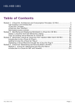
1. You can hide or show individual signals from the graphical view by clicking these buttons.
2. You can move in the x-axis and the y-axis with the mouse by first pressing either of the buttons
and then dragging the scale with a mouse. You can also zoom into the graphic by first pressing
the left mouse button in the start corner and then moving the mouse pointer to the end corner of
the area that you want to zoom and then releasing the mouse button. You can zoom back by
clicking the right mouse button somewhere on the graphics.
3. The trigger point is always shown with a red vertical line.
4. This data table shows the signal names, data types of the signals and the minimum and
maximum scales of the signals. When you open a datalogger log file, the scales are automatically
set to show the whole signal variation in the y scale. You can also change the Scale Min and
Scale Max columns yourself. By clicking the buttons in ‘Auto’ column, you can auto-scale the
signals again.
5. You can auto-scale each of the signals by clicking these buttons.
6. This frame shows the trigger information.
If you zoom into graphics or otherwise change the Y-scales in the graphical window, you can set
the scales back to the limits you have set by clicking the Reset Scales button.
You can also show or hide the Y scales by clicking the Show Y Scales checkbox.
Printing Datalogger graphics
You can print the graphics by selecting Print from the File menu. You can also print the graphics
to a file by selecting Print to File from the File menu.
12
9000XDrive User Manual
Menus
File Menu
New
Opens an application in offline mode.
Open…
Opens previously saved parameter files.
Save
Saves parameters to a file.
Save As…
Asks a file name and saves parameters to a file.
Print Preview
Shows a print preview window.
Print…
Prints parameters or trends depending of the active window.
Print To File…
Prints parameters or trend to a file.
Service Info...
Reads parameters, drive info, active faults and fault history and shows them in a window. You
can
print the contents of this window or save it to a file.
Exit
Exits the program.
Edit Menu
Undo
Undo the last parameter change (F12).
View Menu
Parameters
Shows the parameter window.
Operating
Shows the Operating window.
Monitoring
Shows the Monitoring window.
Diagnostic
Shows the Diagnostic window.
Toolbar
Toggles the Toolbar on and off.
Statusbar
Toggles the Statusbar on and off.
13
9000XDrive User Manual
Drive Menu
Application
Shows the available applications in frequency converter and let’s you change the active
application
in frequency converter.
Language
Shows the languages that the frequency converter software supports and let’s you change the
active language in frequency converter.
Upload
Uploads the parameters from frequency converter to PC.
Download
Downloads the parameters from PC to frequency converter.
Parameter Sets
Allows you to save and load parameter set 1 and 2 in frequency converter.
Info
Shows information of the frequency converter.
Window Menu
Cascade
Rearranges the windows so they overlap in a cascade.
Help Menu
Contents
Shows this help file.
About
Shows information of this program.
14
9000XDrive User Manual
Toolbar
1. New
Open
Save
Print
2. These option buttons show the current program state. Online mode means that every
parameter change that you make in parameter window will immediately be written to a converter
and it also indicates that you are communicating with a converter. You can’t go to online mode if
you don’t have a converter connected to your PC. Offline mode means that the parameter
changes you make are written only to program’s internal memory. You can save these parameter
values to a parameter file and later download them to a converter.
Selecting the Online option button will cause the parameters to be uploaded and a parameter
window to be showed. You can also press the Upload button directly, it will do the same thing as
selecting the Online option button and the mode changes automatically to online mode. You can
even press the Parameter Window button and it will do the same thing.
3. This icon indicates the current program state graphically. There will be a converter connected
to PC in online mode and a file symbol in offline mode.
4. Upload
Download
Parameter Window
Operating Window
Monitoring Window
Diagnostic Window
Drive Select Window
15
9000XDrive User Manual
Parameter Window
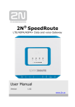
1. This tree view shows the menu structure of the application. The parameter view on the right will
change according to parameter group selection.
2. This table shows the parameters of the selected group or groups. You can change the
parameter’s value simply by clicking the right row and entering a new value to the value column.
You can always undo the last change by pressing F12.
3. The source where the parameters are loaded from is shown here. If you open an application in
offline mode using File|New command, you will open that application with default values and a
word ‘DEFAULTS’ is shown. If you open a previously saved parameter file using File|Open
command, you will get that application with parameter values you have saved and a path and
filename of the parameter file is shown here. If you upload the parameter values from a frequency
converter, a word ‘LOADED’ is shown.
4. If you want to compare the parameter values with default values or with parameter values
saved to a file, press Compare… and select either File or Defaults.
16
9000XDrive User Manual
Compare Parameters
You can compare the parameters you have in your computer against a previously saved
parameter file.
Press the Compare… button in the top of the Parameter window. A dialog will open to select a
parameter file to compare against. After selecting the parameter file a compare window will open:
1. The number of found differences is shown in title bar.
2. Here you can see the source of the values that you are comparing with current parameter
values. The ‘Compared Value’ field shows the value from source file.
3. This column shows the values from the current application. You can also change the
parameter’s value directly in this column.
Example: If you want to compare the values in frequency converter with a parameter file that you
have earlier saved, do the following: Upload the parameters from frequency converter, click
Compare… button and select the parameter file. Click OK and the Parameter Comparison
window will open.
You can print this window by pressing the Print… button.
17
9000XDrive User Manual
Monitoring Window
1. Trend signal table
This table shows the signals you want to monitor in graphical format. Select first the Type of the
signal (Value is default) you want to monitor and then select the signal from Signal name column.
The Actual column shows the signal’s current value. If you want, you can change the signal’s
minimum and maximum scales by changing the Scale min and Scale max columns. The
Autoscaling checkbox will automatically scale the signal to the minimum and maximum values in
the signal buffer. You can change the signal to some other signal simply by selecting a new
signal from the Signal name column.
If you want to delete a signal from the trend signal table, click on that row and press the delete
button.
2. Trend signal view
Maximum of 8 signals can be monitored in the Monitoring page and all the signals are shown in
the same view. You can zoom anywhere in the signal view by dragging a range with a mouse.
You can zoom back to full view by pressing the Reset Scales button, or you can zoom back little
by little by clicking the right mouse button. You can get a vertical ruler to the trend view by clicking
near the left or right edge of the trend view, or a horizontal ruler by clicking near the bottom or top
of the trend view.
3. Y-scale (Signal value scale)
Each signal has its own y-scale. The scale shows the name of the signal and the unit of the
signal.
Minimum and maximum range is by default the signal’s Scale min and Scale max values. You
can change the range by entering new value to Scale min and Scale max columns or by dragging
the Y-scale with mouse. You can use right or left mouse buttons or both.
18
9000XDrive User Manual
4. X-scale (Time scale)
When the signal is selected, the time scale shows by default the whole time range that results
from the Sampling Rate. The signal buffer is 1000 values per signal. If the Sampling Interval is for
example 100 ms, the buffer will cover the time period of 100ms * 1000 samples = 100000ms =
100 s. You can change the visible time scale by dragging the X-scale with mouse.
5. Curve visibility buttons
You can show/hide any signal with these buttons. If you have many signals in measurement, the
monitor view can sometimes be hard to follow. Hide the signals that are not important in that
moment. The monitoring will still continue in the background and when you show the signals
again, they will show the correct values.
6. Curve color
Each signal has a different color. You can quickly see which curve corresponds to which signal by
checking the color.
7. Autoscaling
The Autoscaling checkbox will automatically scale the signal to the minimum and maximum
values in the signal buffer.
8. Control panel
You can start, pause and stop the signal measurement by clicking the corresponding buttons in
the Control panel. These buttons will start, pause and stop ALL the signals at a time.
If you press the Pause button the measurement will still continue in the background and when
you press Run, the curve will show the values measured in the background and continue
normally.
If you press the Stop button the measurement will stop and when you press the Run button again,
the measurement will continue from that point and whatever the signal was in between will not
show in the screen.
The Settings button shows the Monitor Settings window. In Monitor Settings window you can set
the sampling interval of the signals and set triggers.
The Clear button clears all the signal buffers.
The Hide Table button hides the trend signal table and you can see the trends a bit larger. The
Show button will appear after you have selected Hide.
The Reset Scales button resets all the scales to their default values. If you have zoomed to some
signal you can press this button to get back to full view.
The Snapshot button saves either a bmp picture or trn file of the current monitor graphics to a
snapshot directory. You can select which snapshot file is used and what is the snapshot directory
in Options dialog.
9. Trigger Signal
If you have defined a trigger in Monitor Settings window, you can see which signal has the trigger
of the color of the signal name. Red indicates the trigger signal.
10. Point of trigger
When the trigger has fired, the trends will stop and a red marker will appear to the point where the
trigger fired. The place where the marker appears depends on the Post Sampling setting in the
Monitor Settings window.
19
9000XDrive User Manual
Monitor Settings
In the Monitor Settings window you can set the sampling interval of the signals you have selected
in the Monitoring page and set triggers to one of the signals.
1. Sampling Interval setting is used with all the signals. You can’t set different sampling intervals
to different signals.
2. Continuous/Trigger setting defines if you want to set a trigger to some signal or if you just want
to see signals run continuously without triggers. You have to select the Trigger option before you
can set the trigger.
3. Trigger signal table. Select the signal that you want to set the trigger on, and set the trigger
level. Selects also if the trigger will fire on the rising or on thefalling edge. Note that you can only
set the trigger to one of the signals you have selected in Monitoring window.
4. Post-Sampling defines how many samples are still sampled after the trigger has fired.
5. You can temporarily set the trigger of by un-checking this checkbox. When you want to set the
trigger back on, just check this checkbox again.
6. You can set the ‘amount’ how quickly the signal must change before a Derivate trigger fires.
With Derivate ON checkbox you can temporarily set the Derivate trigger off.
20
9000XDrive User Manual
Operating Window
1. Before you can control a motor with 9000XDrive, you have to change the control place to PC.
The control place showing in the status bar of the Operating window is the control place where
the frequency converter’s control is. The PC control ‘overrides’ this control place and when the
PC control is set off, the control returns to the frequency converter’s control place.
2. You can start and stop a motor with Start and Stop buttons and reset faults in frequency
converter with Reset button.
3. You can change the frequency reference by scrolling the reference control with mouse or by
pressing the Page Up and Page Down keys or cursor keys. The Reference will change after you
release the mouse button or keys. You can also set the reference directly by setting the reference
in the textbox showing the reference in numerical value.
21
9000XDrive User Manual
Diagnostic Window
Diagnostic window shows you the active faults in frequency converter as well as fault history
depending on which option button you have selected.
1. Select this option button when you want to see the active faults in frequency converter.
2. Select this option button if you want to see the fault history in frequency converter.
3. This list shows the active faults and fault history. Click on a fault and you get fault time data
record in the list below.
4. This list shows the fault time data record of the fault selected in the list above.
5. You can reset the active fault(s) in frequency converter by pressing this button.
22
9000XDrive User Manual
Drive Tool Options
Ask confirmation before mode is changed from Online to Offline
If this is set, 9000XDrive will ask confirmation every time you change the mode from online to
offline.
Ask confirmation before application is changed in frequency converter
When you change the active application in the frequency converter in Drive|Application page,
9000XDrive will ask confirmation before the application is changed.
Upload parameters automatically after application change
If this is set, 9000XDrive will start uploading the parameters after application is changed in the
frequency converter.
Ask confirmation before automatic upload
If this is set, 9000XDrive will ask confirmation before the parameters are uploaded after the
application is changed in frequency converter. See also Upload parameters automatically after
application change.
If target system SW doesn’t support uploading/downloading system parameters, show a
message after uploading
If this is set, 9000XDrive will show a message box after uploading to remind you that if the system
software in frequency converter doesn’t support uploading and downloading system parameters,
9000XDrive’s Parameter window will not contain system parameters.
Always let the program use the first compatible database and never show the compatible
database list
If this is set, 9000XDrive will work a little bit faster, because it will always automatically open the
first VCN that it finds to contain a compatible application database, and never shows you a list of
VCNs that contain compatible application database. However, if you are developing applications,
you may want 9000XDrive to open a particular database.
23
9000XDrive User Manual
If a compatible VCN is not found, start generating automatically.
If this is set, 9000XDrive will start generating the missing application database automatically.
Application language in 9000XDrive
You can use this combo box to select the language in which the parameter names and similar are
shown in 9000XDrive.
Drive Tool Language
You can use this combo box to select the language in which the menu texts, button texts,
messages and similar (i.e. tool related texts) are shown in 9000XDrive.
Parameter Options
Show parameter table fields
You can select which fields are shown in the parameters page by selecting or de-selecting the
fields in this setting.
Download parameter classes
Every parameter belongs to some parameter class and with this setting you can select which
parameters are downloaded to the frequency converter.
24
9000XDrive User Manual
Monitor Options
Preferences
Show curve symbols on curves in printout
When the monitor page is printed on a black and white printer, it is difficult to see which curve is
which. If this option is checked, graphical symbols are added to curves.
Show warning message when trying to set too small sampling interval
If the sampling interval is too small (compared to the number of signals monitored, and to the can
bus speed), some of the measurements will be lost and there will be ‘gaps’ in the signals. If this
option is checked, the 9000XDrive will show you a warning text.
Show warning message when trying to add too many signals to monitor
See the previous item.
Trend Recording
If manual stop is selected, force stop when there is less than ?? free space in the harddrive
This option forces the 9000XDrive to stop logging to a file when there is less hard-drive space left
than the amount supplied in the combo box.
Trend Snapshot
When the Monitor window is open, you can save snapshot files of the trend by pressing the F2
key on your keyboard. Here you can define the filename for the snapshot files and if you want to
save bmp pictures or trn files. You can also define a directory for the snapshot files. A running
number is added automatically to the end of the filename.
25
9000XDrive User Manual
Fault Options
Default Fault List
Active Faults
Fault History
With this setting you can select which fault list is shown by default, the Active Faults list or
Fault History list.
Automatic open in case of active fault
If this is set, the diagnostic window will pop-up when a fault occurs in frequency converter.
Confirmations
Active Faults
Fault History
If these are set, the 9000XDrive will ask confirmation when you press the Reset button in the
Fault window.
26
9000XDrive User Manual
Operating Options
Controls
Coast button visible
If this is set, the Operating page will show a Coast button.
Confirmations
Start
Stop
Reference control
Direction change
Control location change
These settings will cause the 9000XDrive to ask confirmation before these actions take place.
27
9000XDrive User Manual
Communication
RS232
Comport
This setting tells 9000XDrive which com port you are using to communicate with the frequency
converter.
Baudrate
This setting tells 9000XDrive which baudrate to use to communicate with the frequency converter.
Monbus
Device number of the CAN adapter (0-254)
This is the device number of the CAN adapter (usually 0). Note that this is NOT the Drive Number
of the frequency converter.
Speed
This is the CAN speed.
Can interface
Here you can select the type of the CAN adapter you are using.
28