1
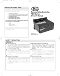
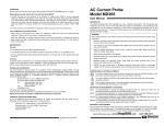
Warranty, Service & Repair
To register your product with the manufacturer, go to the Flowline
website for on-line registration. The website address is as follows:
www.flowline.com
On-line Warranty Registration can be found under Contact
Flowline on the Navigation Bar along the side of the home page.
If for some reason your product must be returned for factory service, go to
the Flowline website listed above. Online Factory Service can be found
under Contact Flowline on the Navigation Bar along the side of the home
page. Click on Return Authorization to begin the registration process.
You will need the following information at the time of registration:
®
Compact Relay Controller
LC10 and LC11 Series
Owner’s Manual
1. Part Number and full Serial Number from product
2. Name and telephone number of someone who can answer
technical questions related to the product and its application.
3. Return Shipping Address
4. Brief Description of the Symptom
5. Brief Description of the Application
Once you have received a Material Return Authorization number,
ship the product prepaid in its original packing to:
Flowline Factory Service
MRA _____
10500 Humbolt Street
Los Alamitos, CA 90720
To avoid delays in processing your repair, write the MRA on the
shipping label. Please include the information about the malfunction with your product. This information enables our service technicians to process your repair order as quickly as possible.
Version 5.2A
© 2007 FLOWLINE Inc.
All rights reserved.
Manual # MNC 11100
09/07
WARRANTY
Flowline warrants to the original purchaser of its products that such
products will be free from defects in material and workmanship under
normal use and service for a period which is equal to the shorter of
one year from the date of purchase of such products or two years from
the date of manufacture of such products.
Products which are thought to be defective must be shipped prepaid
and insured to Flowline’s factory or a designated service center (the
identity and address of which will be provided upon request) within
30 days of the discovery of the defect. Such defective products must
be accompanied by proof of the date of purchase.
This warranty covers only those components of the products which
are non-moving and not subject to normal wear. Moreover, products
which are modified or altered, and electrical cables which are cut to
length during installation are not covered by this warranty.
Flowline further reserves the right to unilaterally wave this warranty
and to dispose of any product returned to Flowline where:
a. There is evidence of a potentially hazardous material present
with product.
b. The product has remained unclaimed at Flowline for longer than
30 days after dutifully requesting disposition of the product.
Flowline’s obligation under this warranty is solely and exclusively
limited to the repair or replacement, at Flowline’s option, of the products (or components thereof) which Flowline’s examination proves to
its satisfaction to be defective. FLOWLINE SHALL HAVE NO
OBLIGATION FOR CONSEQUENTIAL DAMAGES TO PERSONAL OR REAL PROPERTY, OR FOR INJURY TO ANY PERSON.
This warranty does not apply to products which have been subject to
electrical or chemical damage due to improper use, accident, negligence, abuse or misuse. Abuse shall be assumed when indicated by
electrical damage to relays, reed switches or other components. The
warranty does not apply to products which are damaged during shipment back to Flowline’s factory or designated service center or are
returned without the original casing on the products. Moreover, this
warranty becomes immediately null and void if anyone other than service personnel authorized by Flowline attempts to repair the defective
products.
THERE ARE NO WARRANTIES WHICH EXTEND BEYOND
THE DESCRIPTION ON THE FACE OF THIS WARRANTY. This
warranty and the obligations and liabilities of Flowline under it are
exclusive and instead of, and the original purchaser hereby waives, all
other remedies, warranties, guarantees or liabilities, express or
implied. EXCLUDED FROM THIS WARRANTY IS THE IMPLIED
WARRANTY OF FITNESS OF THE PRODUCTS FOR A PARTICULAR PURPOSE OR USE AND THE IMPLIED WARRANTY OF
MERCHANT ABILITY OF THE PRODUCTS.
This warranty may not be extended, altered or varied except by a written instrument signed by a duly-authorized officer of Flowline, Inc.
SAFETY PRECAUTIONS
Step Two
INTRODUCTION
Step Three
About This Manual:
Make a Fail-Safe System:
PLEASE READ THE ENTIRE MANUAL PRIOR TO
INSTALLING OR USING THIS PRODUCT. This manual
includes information on three different models of Compact Relay
Controllers from Flowline: LC10-10_1, LC10-10_2 and LC1110_1. The LC10 is a single-input controller with an optional Strobe
Alert™ on the -10_2 model, and the LC11 is a dual-input controller. Many aspects of installation and use are similar between the
three models.
Design a fail-safe system that accommodates the possibility of relay
or power failure. If power is cut off to the controller, it will de-energize the relay. Make sure that the de-energized state of the relay is the
safe state in your process. For example, if controller power is lost, a
pump filling a tank will turn off if it is connected to the Normally
Open side of the relay.
User’s Responsibility for Safety:
FLOWLINE manufactures several models of controller, with different mounting and switching configurations. It is the user’s
responsibility to select a controller model that is appropriate for the
application, install it properly, perform tests of the installed system,
and maintain all components.
Electrical Shock Hazard:
It is possible to contact components on the controller that carry
high voltage, causing serious injury or death. All power to the controller and the relay circuit(s) it controls should be turned OFF prior
to working on the controller. If it is necessary to make adjustments
during powered operation, use extreme caution and use only insulated tools. Making adjustments to powered controllers is not recommended. Wiring should be preformed by qualified personnel in
accordance with all applicable national, state and local electrical
codes.
Flammable or Explosive Applications:
Sensor mount controllers should not be used with explosive or
flammable liquids, which require an intrinsically safe rating such
as the Flowline LC90 series. If you are unsure of the suitability of
a controller for your installation, consult your Flowline representative for further information.
Install In a Dry Location:
The LC10 and LC11 series controller housing is liquid-resistant
and made of Polypropylene (PP). When installed properly, the controller is not designed to be immersed. It should be mounted in such
a way that it does not normally come into contact with fluid. Refer
to an industry reference to ensure that compounds that may splash
onto the controller housing will not damage it. Such damage is not
covered by the warranty.
Relay Contact Rating:
The relay is rated for a 10 amp resistive load. Many loads (such as
a motor during start-up or incandescent lights) are reactive and may
have an inrush current characteristic that may be 10 to 20 times
their steady-state load rating. The use of a contact protection circuit
may be necessary for your installation if the 10 amp rating does not
provide an ample margin for such inrush currents.
While the internal relay is reliable, over the course of time relay failure is possible in two modes: under a heavy load the contacts may be
“welded” or stuck into the energized position, or corrosion may build
up on a contact so that it will not complete the circuit when it should.
In critical applications, redundant backup systems and alarms must be
used in addition to the primary system. Such backup systems should
use different sensor technologies where possible.
While this manual offers some examples and suggestions to help
explain the operation of FLOWLINE products, such examples are for
information only and are not intended as a complete guide to
installing any specific system.
Sensor-mount controllers:
The LC10/LC11 is a cost-effective, modular liquid level controller
whose body incorporates a female 3/4" NPT (3/4" BSP) fitting, allowing it to be mounted directly onto any Flowline sensor or Switch
Pak™ or any 3/4" connection. Simply provide its required AC power
and a controlled device such as a valve, pump, or alarm that can be
switched by the controller’s relay in response to the sensor input.
Sensor-mount controllers are particularly appropriate for simple
processes such as high or low alarms. They can also be a useful part
of more complicated systems, providing a fail-safe backup in case a
centralized system fails.
Features of the LC10 Single Input Controller:
The LC10 Controller is designed to receive a signal from a single liquid sensor. It turns its internal relay On or Off (as set by the invert
switch) in response to the presence of liquid, and changes the relay
status back again when the sensor is dry. The LC10 may be used with
almost any kind of sensor signal: current sensing, contact closure, or
FET switch. The relay is a single pole, double throw type; the controlled device can be connected to either the normally open or normally closed side of the relay. A time delay from 0 to 60 seconds can
be set before the relay responds to the sensor input.
Typical applications for the LC10 are high level or low level
switch/alarm operations (opening a drain valve whenever liquid level
rises to a sensor point) and leak detection (sounding an alarm when a
leak is detected, etc.).
Features of the LC11 Single Input Controller:
The LC11 Controller is designed to receive signals from two liquid
sensors. It turns its internal relay On or Off (as set by the invert
switch) in response to the presence of liquid on both sensors, and
changes the relay status back again when both sensors are dry. The
LC11 may be used with almost any kind of sensor signal: current
sensing, contact closure, or FET switch. The relay is a single pole,
double throw type; the controlled device can be connected to either
the normally open or normally closed side of the relay. A time delay
from 0 to 60 seconds can be set before the relay responds to the sensor input.
Typical applications for the LC11 are automatic filling (starting fill
pump at a low level and stopping pump at a high level) or automatic
emptying operations (opening a drain valve at a high level and closing valve at low level).
GUIDE TO CONTROLS
INSTALLATION
Step Four
Step Five
3/4" NPT Mounting Thread:
GND
2
NC
R
4
C
LATCH
LA
TCH
1
INVERT +/INVER
1A
AC
ut
3
Inp
AC
P
8
(+)
(-)
Installation of the compact relay controller takes advantage of the
3/4" NPT thread located on its base. This makes the controller fully
compatible with any of Flowline's level switches or Smart Trak™ or
Switch Pak™ mounting systems.
9
5
6
(+)
(-)
NO
115 VAC
220 VAC
DELAY
7
B
t1
8
pu
In
3. AC Power terminals: Connection of 120 VAC power to the controller. The setting may be changed to 240 VAC if desired. This
requires changing internal jumpers; this is covered in the
Installation section of the manual. Polarity (neutral and hot) does
not matter.
4. Relay terminals (NC, C, NO): Connect the device you wish to
control (pump, alarm etc.) to these terminals: supply to the COM
terminal, and the device to the NO or NC terminal as required.
The switched device should be a noninductive load of not more
than 10 amps; for reactive loads the current must be derated or
protection circuits used. When the red LED is ON and the relay is
in the energized state, the NO terminal will be closed and the NC
terminal will be open.
5. Invert switch: This DIP switch reverses the logic of the relay
control in response to the sensor(s): conditions that used to energize the relay will make it turn off and vice versa.
6. Latch switch (LC11 only): This DIP switch determines how the
relay will be energized in response to the two sensor inputs. When
LATCH is OFF, the relay responds to sensor Input 1A only; when
LATCH is ON, the relay will energize or de-energize only when
both sensors (1A and 1B) are in the same condition (wet or dry).
The relay will remain latched until both sensors change states.
7. Time Delay: After the input(s) change(s) state, this control sets a
delay from 0.15 to 60 seconds before the relay will respond.
8. Input 1A and 1B indicator: These amber LEDs will light immediately whenever the appropriate sensor attached to the terminals
detects liquid, and will turn off when it is dry.
9. Input terminals: Connect the wiring from the sensors to these
terminals: A to the upper pair, B (LC11 only) to the lower pair.
Note the polarity: (+) is a 13.5 VDC, 27 mA power supply (to be
connected to the red wire of a Flowline sensor), and (-) is the
return path from the sensor (to be connected to the black wire of
a Flowline sensor). If polarity is reversed, the sensors will not
work.
3"
2. Relay indicator: This red LED will light whenever the controller
energizes the relay, in response to the proper condition at the sensor input(s) and after the time delay.
1"
1. Power indicator: This green LED lights when AC power is ON.
Always tighten the controller
from the wrench flat located
on the swivel base. Never
tighten from the body of the
controller.
Switch Cable:
When installing a Flowline level switch,
adjust the cable away from the printed circuit boards in the controller body. Avoid
breaking the seal between the top of the
level switch and the plastic coated cable.
Connecting switches to input terminals:
Please note a difference between FLOWLINE powered level switches
and reed switches. All powered level switches (models LO10, LP10,
LP15, LP50, LU10, LZ12) will be wired with the Red wire to the (+)
terminal and the Black wire to the (-) terminal. FLOWLINE reed
switches (models LV10, LV20, LV30, LH20 and LH30) will have a particular wiring based upon part number. See the illustration below to
indicate wiring for your switch. Note: the Shield wire will be used only
for long cable runs or where excessive electrical noise is present.
FLOWLINE
Powered Switch
(+) Red
(-)
Models
Models:
LZ10,LU10,
LU10,
LZ10,
LP50,
LP15,
LP50,
LP15,
Red*
LP10,
LP10, LO10,
LO10,
Black* LV10-_201
LV10-_2_1
Black
(+)
(-)
* Terminals available on LC11 Only
FLOWLINE
Reed Switch
(+) White
(-)
Black
White*
Models
Models:
LV10-_3_1
LV10-_301,
LH10
LH10
(+) Black*
(-)
* Terminals available on LC11 Only
INSTALLATION
APPLICATION EXAMPLES
Step Six
Step Seven
VAC Power Input Wiring:
Low Level Alarm
Observe the labeling on the LC10/LC11. Note: Polarity does not matter with the AC input terminal.
The goal is to make sure that the liquid level does not fall below a certain point. If it does, an alarm is supposed to sound, alerting the operator of a low level condition.
HOT
NRTL
GND
HOT
NRTL
GND
If power is accidentally cut to the controller, the sensor's ability to
notify the operator of a low level condition could be lost. The system
must alert the operator not only to low liquid level, but to controller
power loss.
AC
AC
GN
NC
C
NO
AC
AC
GN
NC
C
NO
Relay Input Wiring
The relay is a single pole, double throw type rated at 250 Volts AC,
10 Amps, 1/4 Hp. The two terminal NO and NC (normally open and
normally closed) will be used in different applications. Remember
that the "normal" state is when the relay coil is de-energized and the
Red relay LED is Off / de-energized.
AC
In this application, the normal status if the sensor at the bottom if the
tank will be wet, and the relay will be energized holding the alarm circuit open. Both the relay LED and the Input LED will be on simultaneously, so for this application, Invert should be set to the Off position.
AC
Relay
Terminals
GND
NC
High Level Alarm
C
In the same manor, this system can be used to sound an alarm when
fluid reaches a high level, with just a change in the location of the sensor and the setting of the Invert switch.
NO
Strobe Alert Output
With the Strobe Alert wired NC, it can be used as a high or low level
alarm, depending on the setting for the invert switch. Strobe can also
be wired NO.
AC
AC
P
NC
R
C
NO
Strobe
Changing from 120 to 240 VAC
1. Remove the two screws from the top of the printed circuit board
(PCB) and gently slide the PCB from the housing. Use caution when
removing the PCB.
2. Located jumpers JWA, JWB and JWC on the PCB.
3. To change to 240 VAC, remove jumpers from JWB and JWC and
place a single jumper across JWA. To change to 120 VAC, remove
jumper JWA and place jumpers across JWB and JWC.
4. Gently return PCB into housing and replace the two screws.
240 VAC
Configuration
JWB
JWB
JWA
JWA
120 VAC
Configuration
JWC
The alarm is still connected to the NC side of the relay to allow for a
power failure alarm.
The sensor is normally dry. In this condition, we want the relay to be
energized so the alarm does not sound: i.e., the Red relay LED should
be on whenever the Input LED is Amber. So we turn Invert On. If the
fluid level rises to the high sensor point, the sensor goes on, the relay
de-energizes, and the alarm sounds.
LED Indication:
GND
JWC
To do this, connect the hot lead of the
alarm to the NC side of the relay terminal of the controller. If power is
AC
P
lost, the relay will be de-energized,
GND
and the alarm will sound (if there is
NC
still power to the alarm circuit itself).
R
C
The alarm circuit should have a nonNO
interruptible power supply or some
other indicator or backup alarm to
warn of a power failure in the alarm circuit.
AC
Use LED's located above the input terminals
to indicate whether the switch is in a wet or
dry state. With powered switches, Green
indicates dry and Amber indicates wet. With
reed switches, Amber indicates wet and no
LED indicates dry. Note: reed switches may
be wired in reverse so that wet indicates dry
and Amber indicates dry.
Off
Amber
1A
1B
(-) (+)
(-) (+)
APPLICATION EXAMPLES
TROUBLESHOOTING
Step Eight
Step Nine
Automatic Fill:
Controller Logic
This system consists of a tank with a high level sensor, a low level
sensor, and a pump that is controlled by the controller. Part of a proper fail-safe design for this particular
AC
system is that if power is lost to the
controller for any reason, the pump
AC
P
filling the tank must be turned off.
GND
Therefore, we connect the pump to
NC
the NO side of the relay. When the
R
C
relay is energized, the pump will turn
NO
on and fill the tank. The relay indicator will correspond directly to the
On/Off status of the pump.
For all controllers, please use the following guide to understand the
operation of the FLOWLINE LC11 controllers.
NOTE: If the pump motor load exceeds the rating of the controller’s
relay, a stepper relay of higher capacity must be used as part of the
system design.
1. Power LED: Make sure the Green power LED is On when
power is supplied to the controller.
2. Input LED(s): The input LED(s) on the controller will be Amber
when the switch(es) is/are wet and Off when the switch(es) is/are
dry. Note: see Step 5 regarding reed switches. If the LED's are not
switching the input LED, test the level switch.
3. LC10 only: When the input LED turn Off and On, the relay LED
will also switch. With invert Off, the relay LED will be On when
the input LED is On and Off when the input LED is Off. With
invert On, the relay LED will be Off when the input LED is On
and On when the input LED is Off.
•
When both the high and low sensors are dry, the pump should turn
on, starting to fill the tank.
•
When the low sensor gets wet, the pump should stay on.
4. LC11 only: When both inputs are wet (Amber LED's On), the
relay will be energized (Red LED On). After that, if one switch
becomes dry, the relay will remain energized. Only when both
switches are dry (both amber LED's Off) will the controller deenergize the relay. The relay will not energize again until both
switches are wet. See the Relay Latch Logic Chart below for further explanation.
•
When the high sensor gets wet, the pump should turn off.
Relay Latch Logic Table (LC11 Only):
Determining the settings of LATCH and INVERT
This is the way the system must operate:
Latch: In any two-sensor control system, LATCH must be ON.
Invert: Referring to the logic chart in Step Nine, we look for the setting that will de-energize the relay (start the pump) when both inputs
are wet (Amber LEDs). In this system, Invert should be ON.
Determining A or B input connections: When LATCH is ON,
there is no effective difference between Input A and B, since both sensors must have the same signal in order for status to change. When
wiring any two-input relay section, the only consideration for hooking a particular sensor to A or B is if LATCH will be OFF.
Automatic Empty:
Note that a similar system logic can be used for an automatic empty
operation simply by controlling a pump that pumps fluid out of the
tank instead of into it. However, note the importance of fail-safe
design. If the tank is being passively filled, and a pump must be used
to actively empty it, a power failure to either the controller or the
pump circuits will cause overflow.
Alternatively, an electrically-controlled drain valve could be used. In
this case, the valve should be a type that will automatically open if
power is lost; in other words, power must be used to hold it closed.
The valve would be connected to the NO side of the relay—if power
is lost to the controller, the relay de-energizes, the valve loses the
power that was holding it shut, and fluid will drain from the tank into
some other safe containment until
power is restored. In this system,
AC
whenever the red relay LED of the
AC
P
controller is ON, the drain is closed,
GND
allowing fluid to rise.
In this case, Invert should be On:
when both sensors are wet, the relay
de-energizes, the switch to the valve
opens, and the tank will drain.
NC
R
C
NO
The relay can either be an independent relay (high or low level alarm)
or can be a latching relay (automatic fill or empty) with latch ON.
With Latch Off, the relay will only respond to the INPUT 1A setting.
INPUT 1B will be ignored.
Invert OFF
Input1A
ON
OFF
Input1B
No Effect
No Effect
Latch Off
Relay
ON
OFF
Invert ON
Input1A
ON
OFF
Input1B
No Effect
No Effect
Latch Off
Relay
OFF
ON
With Latch ON, the relay will actuate when INPUT 1A and INPUT 1B
are in the same condition. The relay will not change its condition until
both inputs reverse their state.
Invert OFF
Input1A
ON
OFF
ON
OFF
Input1B
ON
ON
OFF
OFF
Latch Off
Relay
ON
No Change
No Change
OFF
Invert OFF
Input1A
ON
OFF
ON
OFF
Input1B
ON
ON
OFF
OFF
Latch Off
Relay
OFF
No Change
No Change
ON
Caution: Some sensors (particularly buoyancy sensors) may have
their own inverting capability (wired NO or NC). This will change the
logic of the invert switch. Check your system design.