1
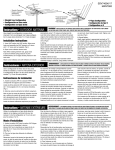
127(7KLVLVDJHQHULFPDQXDO,WHPVVKRZQPD\QRWDSSO\WR\RXUYDFXXP
3OHDVHFRQWDFWFXVWRPHUVHUYLFHZLWKTXHVWLRQV
ATTENTION!
Read all safety rules carefully before attempting to operate. Retain for future reference.
DANGER!
Never operate this unit when
flammable materials or vapors
are present because electrical
devices produce arcs or sparks
that can cause a fire or explosion.
NEVER OPERATE
UNATTENDED!
WARNING!
Do NOT use this vacuum cleaner
to vacuum lead paint debris
because this may disperse fine
lead particles into the air. This
vacuum cleaner is not intended
for use under EPA Regulation
40 CFR Part 745 for lead paint
material cleanup.
IMPORTANT SAFETY INSTRUCTIONS
When using an electrical appliance, basic precautions should always be followed, including the
following: READ ALL INSTRUCTIONS BEFORE USING THIS APPLIANCE.
13. Turn off all controls before unplugging.
14. Use extra care when cleaning on stairs.
15. Do not use to pick up flammable or combustible liquids such as gasoline or use in areas
where they may be present.
16. Do not use your cleaner as a sprayer of flammable liquids such as oil base paints, lacquers,
household cleaners, etc.
17. Do not vacuum toxic, carcinogenic, combustible or other hazardous materials such as
asbestos, arsenic, barium, beryllium, lead, pesticides or other health endangering materials.
Specially designed units are available for these purposes.
18. Do not pick up soot, cement, plaster or drywall dust without cartridge filter and collection filter
bag in place. These are very fine particles that may pass through the foam and affect the
performance of the motor or be exhausted back into the air. Additional collection filter bags
are available.
19. Do not leave the cord lying on the floor once you have finished the cleaning job. It can become
a tripping hazard.
20. Use special care when emptying heavily loaded tanks.
21. To avoid spontaneous combustion, empty tank after each use.
22. The operation of a utility vac can result in foreign objects being blown into eyes, which can
result in eye damage. Always wear safety goggles when operating vacuum.
23. STAY ALERT. Watch what you are doing and use common sense. Do not use vacuum
cleaner when you are tired, distracted or under the influence of drugs, alcohol or medication
causing diminished control.
24. WARNING! Do NOT use this vacuum cleaner to vacuum lead paint debris because this
may disperse fine lead particles into the air. This vacuum cleaner is not intended for use
under EPA Regulation 40 CFR Part 745 for lead paint material cleanup.
WARNING – TO REDUCE THE RISK OF FIRE, ELECTRIC
SHOCK OR INJURY:
1.
Do not leave appliance when plugged in. Unplug from outlet when not in use and before
servicing. Connect to a properly grounded outlet only. See Grounding Instructions.
2. Do not expose to rain – store indoors.
3. Do not allow to be used as a toy. Close attention is necessary when used by or near children.
4. Use only as described in this manual. Use only Manufacturer’s recommended attachments.
5. Do not use with damaged cord or plug. If appliance is not working as it should, has been
dropped, damaged, left outdoors or dropped into water, contact Shop-Vac Corporation for
assistance.
6. Do Not: pull or carry by cord, use cord as a handle, close a door on cord or pull cord around
sharp edges or corners. Do not run appliance over cord. Keep cord away from heated surfaces.
7. Do not unplug by pulling on cord. To unplug, grasp the plug; not the cord.
8. Do not handle plug or appliance with wet hands.
9. Do not put any object into openings. Do not use with any openings blocked; keep free of dust,
lint, hair and anything that may reduce air flow.
10. Keep hair, loose clothing, fingers and all parts of body away from openings and moving parts.
11. Do not pick up anything that is burning or smoking, such as cigarettes, matches or hot ashes.
12. Do not use without dust bag and/or filters in place.
SAVE THESE INSTRUCTIONS
WARNING– DO NOT LEAVE VACUUM UNATTENDED WHEN IT IS PLUGGED IN AND/OR OPERATING. UNPLUG UNIT WHEN NOT IN USE.
GROUNDING INSTRUCTIONS
This appliance must be grounded. If it should malfunction or breakdown, grounding provides a
path of least resistance for electric current to reduce the risk of electric shock. This appliance is
equipped with a cord having an equipment-grounding conductor and grounding plug. The plug
must be inserted into an appropriate outlet that is properly installed and grounded in accordance
with all local codes and ordinances.
the plug illustrated in sketch A. A
temporary adapter that looks like
the adapter illustrated in sketches
B and C may be used to connect
this plug to a 2-pole receptacle
as shown in sketch B if a properly
grounded outlet is not available.
The temporary adapter should be
used only until a properly grounded
outlet (sketch A) can be installed
by a qualified electrician. The
green colored rigid ear, lug or the
like extending from the adapter must be connected to a permanent ground such as a properly
grounded outlet box cover. Whenever the adapter is used, it must be held in place by a metal
screw.
WARNING – IMPROPER CONNECTION OF THE EQUIPMENT-
GROUNDING CONDUCTOR CAN RESULT IN A RISK OF ELECTRIC
SHOCK. CHECK WITH A QUALIFIED ELECTRICIAN OR SERVICE
PERSON IF YOU ARE IN DOUBT AS TO WHETHER THE OUTLET IS
PROPERLY GROUNDED. DO NOT MODIFY THE PLUG PROVIDED
WITH THE APPLIANCE – IF IT WILL NOT FIT THE OUTLET, HAVE A
PROPER OUTLET INSTALLED BY A QUALIFIED ELECTRICIAN.
IN CANADA, THE USE OF A TEMPORARY ADAPTER IS NOT PERMITTED BY THE
CANADIAN ELECTRICAL CODE. Make sure that the appliance is connected to an outlet having
the same configuration as the plug. No adapter should be used with this appliance.
This appliance is for use on a nominal 120-volt circuit, and has a grounded plug that looks like
EXTENSION CORDS
Before using appliance, inspect power cord for loose or exposed wires and damaged insulation.
Make any needed repairs or replacements before using your appliance. Use only three-wire outdoor extension cords which have three-prong grounding-type plugs and three-pole receptacles
which accept the extension cord’s plug. When vacuuming liquids, be sure the extension cord
connection does not come in contact with the liquid.
When using the appliance at a distance where an extension cord becomes necessary, a 3-conductor grounding cord of adequate size must be used for safety, and to prevent loss of power and
overheating. Use the table below to determine A.W.G. wire size required. To determine ampere
rating of your vacuum, refer to nameplate located on rear of motor cover.
Total length of cord in feet
Volts
150
25
50
100
120V
Ampere Rating
AWG
More Not More
Than
Than
18
16
16
14
0
- 6
18
16
14
12
6
- 10
16
16
14
12
10 - 12
14
12 Not recommended
12 - 16
NOTE: STATIC SHOCKS ARE COMMON IN DRY AREAS OR WHEN THE RELATIVE HUMIDITY OF THE AIR IS LOW. THIS IS ONLY TEMPORARY AND DOES NOT AFFECT THE USE
OF THE APPLIANCE. TO REDUCE THE FREQUENCY OF STATIC SHOCKS IN YOUR HOME,
THE BEST REMEDY IS TO ADD MOISTURE TO THE AIR WITH A CONSOLE OR INSTALLED
HUMIDIFIER.
UNPACKING
4. Before replacing cover, please refer to Dry Pick up or Wet Pick up operation to ensure proper
filter installation.
5. Replace cover and make sure latches or clamps are secured over raised area of tank cover.
I=ON, O=OFF
1. Remove vacuum cleaner and all accessories from the carton.
2. Important: Open tank cover by pushing latches or clamps outward with thumbs and remove
any accessories that may have been shipped in the tank.
3. Assemble dolly or caster system following instructions.
ASSEMBLY
5. Insert casters into feet by placing stem of caster into holes provided. Apply pressure and
twisting motion until casters snap into place (Figure 23). Return tank to upright position.
TOP HANDLE ASSEMBLY
(Not standard with all models)
To attach top handle, align holes in handle and holes in tank cover and secure
with screws provided (Figure 1).
17
16
1
18
A
B
20
TOOL HOLDER ASSEMBLY
A
A
10
1. With cord disconnected from receptacle and tank cover removed, turn tank upside down so
that the bottom is facing up.
2. Take rear caster dolly and place into slots (on rear of tank, opposite of drain) and secure with
screws provided (Figure 27).
3. If flat washers are included in hardware package place flat washer over stem of caster before
installing casters into feet. NOTE : Flat washers are not required with all units.
4. Insert casters into bottom of rear caster dolly by placing stem of caster into holes provided.
Apply pressure and twisting motion until casters snap into place (Figure 28).
5. With tank drain facing you, take caster foot marked with the letter A (Figure 29) and place
in slot on left side of tank also marked with the letter A. Secure with screw provided (Figure
30).
6. Take caster foot marked with the letter B (Figure 31) and place in slot on right side of tank
also marked with the letter B. Secure with screw provided (Figure 32).
7. Insert casters into feet by placing stem of casters into holes provided. Apply pressure and
twisting motion until casters snap into place (Figure 33).
8. Return tank to upright position.
9. Place tool basket (not standard with all models) with curved surface against tank on rear
caster dolly assembly (Figure 34).
A
A
33
32
34
A
B
A
B
REAR CASTER ACCESSORY CADDY AND
FRONT CASTER FEET ASSEMBLY
11
(Not standard with all models)
35
You will find four casters, two caster feet, an accessory caddy and four screws
with your wet/dry vacuum.
If your accessory caddy looks like the one pictured in (Figure 35) assemble as
follows.
1. With cord disconnected from receptacle and tank cover removed, turn tank 36
upside down so that the bottom is facing up.
2. Insert two caster feet into adjacent slots at front of tank. Secure with screws
provided.
3. Take accessory caddy and place into remaining slots at back of tank. Secure
with screws provided (Figure 36).
4. Install casters into caddy and feet by inserting the caster stems into the holes
provided. Apply pressure and twisting motion until casters snap into place.
15
A
B
A
B
31
A
14
30
A
A
B
29
28
27
A
B
26
25
24
5-8 U.S. Gallons (18.9 - 30.2L) With Caster Feet
You will find four caster feet (Figure 7), four casters (Figure 8), and four screws with your wet/
dry vacuum. Assemble as follows:
1. With cord disconnected from receptacle and tank cover removed, turn tank 7
upside down so that bottom is facing up.
2. Remove any webbing that attaches the caster feet to each other.
3. With front of tank inlet facing you, take caster feet marked with the letter A
(Figure 9) and insert stem of caster foot into holes on left front and right rear
of tank also marked with letter A (Figure 10). Make sure caster feet are fully 8
inserted into tank bottom and secure with screws provided (Figure 11).
4. Take caster feet marked with the letter B (Figure 12) and insert stem of
caster foot into holes on right front and left rear of tank also marked with
the letter B (Figure 13). Make sure caster feet are fully inserted into tank
bottom and secure with screws provided (Figure 14).
5. Insert casters into feet by placing stem of caster into holes provided. Apply pressure and
twisting motion until casters snap into place (Figure 15).
6. Return tank to upright position.
B
B
B
Without Caster Feet
You will find four casters (Figure 5) with your wet/dry vacuum. Assemble as follows:
1. With cord disconnected from receptacle and tank cover removed, turn tank upside down so
that bottom is facing up.
6
5
2. Insert casters into bottom of tank by placing stem of caster
into holes provided. Apply pressure and twisting motion
until casters snap into place (Figure 6).
3. Return tank to upright position.
13
B
With Rear Caster Dolly/Tool Holder
You will find four casters (Figure 24), two caster feet (Figure 25), rear caster dolly/tool holder
(Figure 26), and four screws with your wet/dry vacuum. Assemble as follows:
CASTER SYSTEM ASSEMBLY
A
A
B
1RW DOO XQLWV DUH HTXLSSHG ZLWK WKH VDPH FDVWHU V\VWHP )ROORZ WKH
LQVWUXFWLRQVZKLFKDSSO\WR\RXUVSHFLILFXQLW
12
23
22
B
4
3
A
21
B
(Not standard with all models)
1. With rear of unit facing you, take tool holder and position it with tabs facing rear
of unit (Figure 2).
2. Place “J” shaped tabs into the slots on cord wraps (Figure3).
3. Press down until tabs snap into place.
4. Press down on center of tool holder until tab latches on bottom of lid (Figure 4).
9
19
A
A
2
A
A
B
B
10 U.S. Gallons (37.8L) and Up With Caster Feet
You will find four caster feet, four casters and four screws (Figure 16) with your wet/dry vacuum.
Assemble as follows:
1. With cord disconnected from receptacle and tank cover removed, turn tank upside down so
that bottom is facing up.
2. With front of tank facing you, take caster feet marked with the letter A (Figure 17) and place
in slots on left front and right rear of tank also marked with the letter A (Figure 18). Secure
with screws provided (Figure 19).
3. Take caster feet marked with the letter B (Figure 20) and place in slots on right front and left
rear of tank also marked with the letter B (Figure 21). Secure with screws provided (Figure
22).
4. If flat washers are included in hardware package place flat washer over stem of caster before
installing casters into feet. NOTE: Flat washers are not required with all units.
If your accessory caddy looks like the one pictured in (Figure 37) assembly as follows.
1. With cord disconnected from receptacle and tank cover removed, turn tank upside down so
that the bottom is facing up.
2. Take accessory caddy and place into slots (on rear of tank opposite of drain). Secure with
screws provided (Figure 38).
3. With tank drain facing you, take caster foot marked with the letter A (Figure 39) and place
in slot on left side of tank also marked with the letter A. Secure with screw provided (Figure
40).
4. Take caster foot marked with the letter B (Figure 41) and place in slot on right side of tank
also marked with the letter B. Secure with screw provided (Figure 42).
5. If flatwashers are included in hardware package place flatwasher over stem of caster before
installing casters into feet or accessory caddy. NOTE: Flatwashers are not required with all
units.
6. Install casters into caster feet and accessory caddy by inserting the caster stems into the
holes provided. Apply pressure and twisting motion until caster snap into place (Figure 43 &
44).
39
40
A
41
44
B
REAR WHEEL DOLLY/TOOL HOLDER
AND FRONT CASTER FEET ASSEMBLY
(Not standard with all models)
You will find two casters (45), two large rear wheels (46), one axle (47), rear dolly/
basket (48), two caster feet (49) and four screws with your wet/dry vacuum. Assemble as follows:
47
46
You will find four casters (Figure 69) and one dolly (Figure 70) with your wet/dry
vacuum. Assemble as follows:
69
54
57
56
CASTER FEET AND CASTER ASSEMBLY
FOR METAL TANKS
You will find two casters (a), two axle housings (b), two wheel plugs (c), two wheels (d), and two
screws with your wet/dry vacuum. Assemble as follows:
b
c
72
58
ASSEMBLY FOR
All AROUND PLUS® SERIES
a
70
1. With cord disconnected from receptacle and tank cover removed, turn tank upside down so
that bottom is facing up.
2. Take dolly and slide onto bottom of tank making sure to line up screw holes on dolly with
screw holes on tank. Secure with screws provided (Figure 71).
3. Install casters into dolly by inserting the caster stems into the holes provided. Apply pressure and twisting motion until the casters snap into place (Figure 72).
4. Return tank to upright position.
71
55
68
DOLLY AND CASTER ASSEMBLY FOR
All AROUND PLUS® SERIES
5. Take rear dolly assembly and place into slots (on rear of tank opposite drain) and secure with
screws provided (Figure 53).
6. With tank drain facing you, take caster foot marked with the letter A (Figure 54) and place in
slot on left side of tank also marked with the letter A and secure with screw provided (Figure
55).
7. Take caster foot marked with the letter B (Figure 56) and place in slot on right side of tank
also marked with the leter B and secure with screw provided (Figure 57).
50
8. Insert casters into feet by placing stem of caster into holes provided. Apply
pressure and twisting motion until casters snap into place (Figure 58).
9. Return tank to upright position.
53
66
(Not standard with all models)
67
1. With rear of tank facing you, take accessory basket
and position with tabs facing rear of tank (Figure 67).
2. Insert tabs of accessory basket into slots on rear of
tank (Figure 68).
3. Press down until basket is secured into place.
4. Slide remaining wheel onto axle and hammer on second cap nut (Figure 52).
52
64
ACCESSORY BASKET ASSEMBLY
49
48
1. With cord disconnected from receptacle and tank cover removed, turn tank upside down so that
the bottom is facing up.
2. Place axle upright on a hard surface and hammer on (1) cap nut. Place (1) wheel on axle and slide
down to cap nut (Figure 50). Be sure flat side of wheel hub is facing outward.
3. Slide axle through holes provided in dolly/basket (Figure 51).
51
63
TOOL HOLDER ASSEMBLY
B
45
62
1. Replace tank cover and apply pressure with thumbs 65
to each latch until it snaps tightly in place. Make sure
both lid latches are clamped securely.
2. With rear of unit facing you, take tool holder and
position it with the tabs facing rear tank cover (Figure
65).
3. Press tabs of tool holder into the slots on mounting
lugs on rear of tank cover (Figure 66).
4. Press down until tabs snap into place.
NOTE: TOOL HOLDER NOT COMPATIBLE WITH ACCESSORY BASKET.
A
A
61
A
43
42
60
d
1. With cord disconnected from receptacle and tank cover removed, turn tank upside down so
that the bottom is facing up with the inlet towards you (Figure 59).
2. Insert casters into bottom of tank by placing stem of caster into holes provided. Apply pressure and twisting motion until casters snap into place (Figure 60).
3. Mount wheel onto axle with smooth face of wheel outward (Figure 61).
4. Insert wheel plug through wheel and axle housing turning wheel plug until it seats flush with
outside of wheel (Figure 62).
5. Insert screw provided through back of axle housing (Figure 63).
6. Slide axle housing into dovetail slot at rear of tank: axle housing is tapered and should slide
into dovetail slot without excessive force (Figure 64). Tighten screw.
7. Repeat steps 3 through 6 for other wheel assembly.
8. Return tank to upright position.
(Not standard with all models)
1. With cord disconnected from receptacle and tank cover
removed, turn tank upside down so that the bottom is
facing up.
2. With a pair of scissors, trim the enclosed template to fit
your size tank. Sizes will be 11”, 14” or 16” diameters.
3. Once template is cut out, place on bottom of tank. Align
inlet arrow on template with center of inlet on tank
(Figure 73).
4. If caster feet are attached together, separate by removing webbing.
5. Take caster foot marked with the letter A and align arrow
on foot (Figure 74) with arrow on template also marked
with the letter A (Figure 75).
6. Place groove of foot over rim of tank and push until the
caster foot is tight against bottom of tank (Figure 76).
7. Secure feet with screw and washer when provided
(Figure 77).
74
73
Template
Arrow
B
A
A
B
A
38
37
59
Bottom of Tank
75
76
Tank bottom
A
77
78
8.
Insert casters into feet by placing stem of caster into holes provided. Apply pressure and
twisting motion until casters snap into place (Figure 78). 11
9. Repeat steps 3-8 with remaining feet.
10. Return tank to upright position.
9.
ITEM NUMBER & DESCRIPTION
1.
2.
3.
4.
5.
6.
REAR WHEEL DOLLY/TOOL HOLDER
AND FRONT CASTER FEET ASSEMBLY
FOR METAL TANKS
(Not standard with all models)
You will find two casters (79), two large rear wheels (80), one axle (81), rear dolly (82), two
caster feet (83) and four screws with your wet/dry vacuum. Assemble as follows:
1.
2.
3.
4.
5.
6.
7.
8.
9.
10.
11.
12.
13.
14.
15.
82
81
80
79
3
10
9
8
Tank
37
Machine
A
B
89
91
90
Tank
Machine
Screw
6
Dolly
4
Hex
Nut
Bottom of Tank
Flat
Washer
ITEM NUMBER & DESCRIPTION
1. Metal tank handle
2. Side tank handle
3. #10 x 3/4" Screw hex head
4. Bolt 1/4 - 20 x 1/2"
5. 1/4 - 20 Hex nut
3
5
1
2
4
SIDE TANK HANDLE ASSEMBLY
Template
A
7
Screw
(Not standard with all models)
Attach side handles to tank with screws provided (Figure 97).
Bottom of Tank
88
5
1
87
B
7. #8 x 1/2" lg. Screw
8. 1/4 - 20 x 3/4" lg.
Machine screw
9. 1/4" Flatwasher
10. 1/4 - 20 Hex nut
11. Caster
11
83
86
85
Cap nut
8" wheel
Axle
Rear frame
Caster socket
Front frame
2
With cord disconnected from receptacle and tank cover removed, turn tank upside down
so that the bottom is facing up.
Place axle upright on a hard surface and hammer on (1) cap nut. Place (1) wheel on axle
and slide down to cap nut (Figure 84). Be sure flat side of wheel hub is facing outward.
Slide axle through holes provided in dolly (Figure 85).
Slide remaining wheel onto axle and hammer on second cap nut (Figure 86).
With a pair of scissors, trim the enclosed template to fit your size tank. Sizes will be 11”,
14” or 16” diameters.
Once template is cut out, place on bottom of tank, align inlet arrow on template with center
of inlet on tank (Figure 87).
Align cutouts in center of rear dolly with bars on template (Figure 88).
Place groove of rear dolly over rim of tank and push until the dolly is tight against bottom
of tank (Figure 89).
Secure dolly with screw and washer provided (Figure 90).
If caster feet are attached together, separate by removing webbing.
Take caster foot marked with the letter A and align arrow on foot (Figure 91) with arrow
on template also marked with the letter A (Figure 92).
Place groove of foot over rim of tank and push until the caster foot is tight against
bottom of tank (Figure 93).
Secure feet with screw and washer provided (Figure 94).
Insert casters into feet by placing stem of caster into holes provided. Apply pressure and
twisting motion until casters snap into place (Figure 95).
Place tool basket (not standard with all models), with curved surface against tank, on
rear wheel dolly assembly (Figure 96).
84
Insert basket (if provided) through center of carriage handle and slide into place.
97
92
Arrow
A
FOUR WHEEL HEAVY DUTY DOLLY
ASSEMBLY
A
93
94
95
96
(Not standard with all models)
Tools required:
(2) 1/2 inch open end wrenches, (2) 7/16 inch open end wrenches, or a socket set and a hammer.
1. Insert 21/2 inch long bolt through center hole in rear frame, attach split lockwasher and nut
and tighten securely.
2. Attach handle brace to back of rear frame with 5/8 inch long machine screws, lockwashers, and nuts. (Finger tighten only.)
3. Position main frame inside rear frame. Attach (2) 5/8 inch long machine screws, lockwashers and nuts in both sides. Tighten securely.
4. Attach handle uprights, inside main frame (make sure buttons at top face inward) using 5/8
inch long machine screws, lockwashers and nuts. (Finger tighten only.) Align holes at top
of handle braces with holes in handle uprights. Attach with 11/4 inch long machine screws,
lockwashers and nuts. (Tighten securely.)
5. Go back and tighten machine screws at bottom of uprights and braces.
6. Attach caster sockets (open end down) to front of main frame using 5/8 inch long
machine screws, lockwashers and nuts. Insert casters into sockets.
7. Slide basket adapters on handle.
8. See Figure 98 and Figure 99 for correct installation of adapters.
9. Attach handle onto uprights by pushing down and holding buttons in on uprights.
10. Place tank retaining bracket through slot and bolt in rear frame and screw on knob.
11. Slide bumper down over main dolly frame until it bottoms out.
12. Place axle upright on a hard surface and hammer on (1) cap nut. Place (1) wheel on axle
Tank Bottom
DOLLY, CARRIAGE HANDLE AND
BASKET ASSEMBLY FOR METAL TANKS
(Not standard with all models)
1. Remove head from tank and place tank upside down on a flat surface.
2. Place wheels on rear frame/axle assembly with extended hub of wheel towards dolly
frame and place cap nuts on axle. Secure with hammer.
3. Insert caster socket into front frame and secure with phillips head screw.
4. Place groove in front frame into lip of tank and position so frame is directly above inlet.
5. Position grooves of rear frame into lip of tank and align so rear and front frames engage.
6. Secure dolly frame to tank by placing machine screws up through holes in dolly frame.
Ensure head of screw is fully recessed in area provided. After machine screw is inserted,
tighten with flatwasher and hex nut.
7. Insert caster in caster socket and apply downward pressure until caster snaps into place.
8. Return vacuum to upright position. Attach carriage handle to tank by inserting bolt through
the center hole of handle and tank, secure with nut provided. Attach side handles with
screws provided. Be sure to spread ends of carriage handle when assembling to prevent
damage to tank.
and slide down to cap nut. Slide axle through rear of frame and slide on other wheel.
Before assembling cap nut on other end of axle, be certain dolly is assembled correctly.
(You may place tank on dolly and tighten knob of retaining bracket to be sure of correct
assembly.)
13. After ensuring dolly is assembled correctly remove tank and place dolly on side with
installed cap nut on hard surface and hammer second cap nut on axle.
14. Place accessory basket on adapters and pull out on outer rim of basket and snap into
place (Figure 100).
For 14" Diameter Tanks
BAND DOLLY ASSEMBLY
(Not standard with all models)
1. Place casters into sockets on band assembly.
2. Place tank upside down and slip band assembly over lip on bottom of tank.
3. Insert bolt and tighten nut until secure.
ITEM NUMBER & DESCRIPTION
1.
2.
98
Handle
Handle
Handle
55 Gal. band assembly
Caster
3.
4.
1
4
For 16" Diameter Tanks
99
Tank
Handle
Handle
2
3
Handle
Basket
Basket
Basket
Adapter
Adapter
Hex head bolt, 1/4 - 20 x 13/4
Hex nut, 1/4 - 20
Basket
Adapter
FILTRATION
Pull Outward
on Basket
Keep Filters Clean
100
The efficiency of these vacuum cleaners is largely dependent on the filter.
A clogged filter can cause overheating and possibly damage the vacuum cleaner.
Clean or replace filters regularly. Do not use the vacuum or filters for collecting hazardous or
other health endangering materials.
NOTE: Never machine wash or dry filters.
DRY PICK UP OPERATION
INSTALLING FOAM SLEEVE AND
REUSABLE DRY FILTER
ITEM NUMBER & DESCRIPTION
1.
2.
3.
4.
5.
6.
7.
8.
9.
10.
11.
12.
13.
14.
15.
Handle
Handle upright
Handle brace
1/4 - 20 x 11/4" Hex head
machine screw (Black)
1/4" External tooth
lockwasher
1/4 - 20 Hex nut (Black)
Rear dolly frame
Main dolly frame
5/16 - 18 x 21/2" Hex head bolt
5/16" Split lockwash
5/16 - 18 Hex nut
16.
17.
18.
19.
20.
21.
22.
23.
Tank retainer bracket
Threaded knob
Axle
1/4 - 20 x 5/8" Hex head
machine screw
1/4 - 20 Hex nut
Caster socket
Caster
Bumper
10" Wheel (25.4cm)
Cap nut
Accessory basket
Basket adapter
(Not standard with all models)
WARNING – ALWAYS DISCONNECT THE PLUG FROM THE
WALL OUTLET BEFORE REMOVING THE TANK COVER.
To pick up dust and dry material, you must install foam sleeve and reusable dry filter to ensure
proper filtration. If the vacuum has been used to pick up liquids, the foam sleeve must be
cleaned and dried before installing for dry pick up.
With tank cover in an upside down position, slide foam sleeve down over lid cage pulling until
foam sleeve completely covers lid cage (Figure 101). NOTE: Bottom of foam sleeve must be
positioned on the OUTSIDE of groove around lid cage for the reusable dry filter to fit properly
(Figure 102, 103). Center the reusable dry filter on lid cage (Figure 104), slide mounting
ring down over filter until ring is positioned against the ribs of the lid cage (Figure 105). The
reusable dry filter should always be in position over the foam sleeve for dry pick up. To remove
the filter for cleaning, remove mounting ring and filter from lid cage (Figure 106). To clean the
reusable dry filter, shake off excess dirt and dust or (depending on the condition of the filter)
rinse with water. Allow the filter to dry completely and re-install. DO NOT MACHINE WASH OR
DRY.
IMPORTANT: BEFORE INSTALLING REUSABLE FILTER BE SURE THAT FOAM SLEEVE IS
OUTSIDE OF GROOVE AND AROUND LID CAGE (Figure 102, 103).
NOTE: ENSURE THAT THE MOUNTING RING IS COMPLETELY SECURE AND IN POSITION BY PRESSING DOWN FIRMLY AROUND THE RING IN SEVERAL PLACES. BE SURE
THE REUSABLE DRY DISC FILTER COMPLETELY COVERS THE FOAM SLEEVE. CHECK
TO ENSURE THAT ALL EDGES OF THE REUSABLE DRY FILTER ARE SECURE UNDER THE
MOUNTING RING.
1
4
5
22
6
23
23
3
15
2
15
14
7
10
11
13
CAUTION – Keep Filters Clean
12
5
20
16
101
5
9
19
21
17
15
8
15
18
102
103
106
105
104
WARNING FOR FINE DUST & POWDERS
When vacuuming fine dust, or powders of any kind (ex. plaster, drywall dust, cold ashes, concrete dust, etc.)...a high efficiency drywall filter bag must be used. When vacuuming normal
household dust and debris, standard household disposable filter bags may be used. These
"large bag" filters connect to the air inlet fitting on the inside of the vacuum tank.
INSTALLING CARTRIDGE FILTER
FILTER SELECTION GUIDE
(Not standard with all models)
NOTE: If foam sleeve is in position over lid cage for some models, it does not need to be
removed before installing cartridge. Foam must be positioned on the INSIDE of groove around
lid cage for cartridge to fit properly.
The cartridge filter can be used for wet or dry pick up; installation is the same for both. When
picking up large quantities of water we recommend using the foam sleeve (not standard with
all models) in position over the lid cage. Use the cartridge filter in position over the lid cage for
most general dry material pxick up. With the tank cover in an upside down position, slide the
cartridge filter down over the lid cage, pushing until the filter seals against the cover (Figure
107). Place filter retainer into the top of the cartridge filter, hold the tank cover with one hand,
turn the handle on the filter retainer clockwise to tighten, locking the filter into place (Figures
108 & 109). To remove the filter for cleaning, again hold the tank cover and turn the filter
retainer counter-clockwise to loosen and remove, slide the cartridge filter off the lid cage (Figures 110 & 111). To clean the cartridge filter shake or brush off excess dirt or rinse (from the
inside of the filter) with water, dry completely (approximately 24 hours) and re-install. (Figures
112). NOTE: IF THE FILTER HAS BEEN USED FOR WET PICK UP, IT MUST BE CLEANED AND
DRIED BEFORE USING FOR DRY PICK UP.
107
108
109
110
111
112
SIZE
5-8 U.S. Gal (18.9-30.3L)
10-14 U.S. Gal (37.8-53L)
15-22 U.S. Gal (56.8-83.2L)
116
Standard
Household
90661/90532
90662/90534
90663/90533
90107 REUSABLE DRY FILTER AND MOUNTING RING
fits all Shop-Vac ® Wet/Dry Vacuums.
90585 FOAM SLEEVE fits all Shop-Vac ® Wet/Dry
Vacuums and should remain in place
at all times.
Remove ALL dirt and debris found in the tank. The vacuum requires only a minimum of conversion when going from dry to wet pick up. Remove all dry use filters from the vacuum. Wet
pick up requires the foam sleeve (not standard with all models) or cartridge filter (not standard with all models) to be in position over the lid cage. For proper installation instructions
for wet pick up using the cartridge filter or foam sleeve, refer to Installing the Cartridge Filter.
Do not use the reusable dry filter for wet pick up. Remove inlet deflector from the deflector
guide sliding in an upward motion. NOTE: Hose must be removed before inlet deflector can
be taken out. Reinstall being sure the opening of the inlet deflector is facing the top of the tank
misting may occur if inlet deflector is not inserted properly. Misting in exhaust air may occur if
the filter becomes saturated during wet pick up If misting occurs, remove filter and allow to dry
or, replace with another dry filter to eliminate the misting and possible dripping of liquid around
the lid. Turn the unit off immediately upon completing a wet pick up job or when tank is full and
ready to be emptied. Raise the hose to drain any excess liquid into the tank. The interior of the
tank should be periodically cleaned.
The foam sleeve should be cleaned periodically as described in the following steps:
1. Always disconnect the plug from the wall receptacle before removing the tank cover. Place
tank cover in an upside down position. Remove foam sleeve by sliding it up and off the lid
cage.
2. Shake excess dust off foam sleeve with a rapid up and down movement.
3. Hold foam sleeve under running water for a minute or two, rinsing from the inside. A water
wash is not always required, depending on the condition of the foam sleeve.
4. Gently wring out excess water, blot foam sleeve with a clean towel, and allow to dry. The
foam sleeve is now ready to be reinstalled on the lid cage.
NOTE: WET PICK UP ACCESSORIES SHOULD BE WASHED PERIODICALLY, ESPECIALLY
AFTER PICKING UP WET, STICKY KITCHEN ACCIDENTS. THIS CAN BE ACCOMPLISHED
WITH A WARM SOLUTION OF SOAP AND WATER.
(Not Standard with All Models)
1. Use for dry pick up only. Use in conjunction with cartridge filter for picking up soot, cement,
plaster or drywall dust.
2. With cord disconnected from receptacle, pull latches in an outward motion and remove
tank cover.
3. Unscrew hose locking-nut and remove hose from inlet (Figure 113).
4. Remove inlet deflector from deflector guide (Figure 114). NOTE: Hose must be removed
before inlet deflector can be taken out.
5. With the opening of the inlet deflector facing the bottom of the filter bag, slide collection
bag collar over deflector matching notches of bag collar to tabs on inlet deflector, bag will
only fit properly one way (Figure 115).
6. Slide deflector with collection bag attached into deflector guide (Figure 116).
7. Reinsert hose into inlet and tighten locking-nut (Figure 117).
8. When secured in place, expand bag and position around the inside of the tank.
Locking Inlet:
OPERATION
This equipment incorporates parts such as switches, motors or the
like that tend to produce arcs or sparks that can cause an explosion.
Do not pick up flammable, combustible, or hot materials. Do not use
around explosive liquids or vapors, as electrical devices produce arcs
or sparks which can cause a fire or explosion - do not use at filling
stations or anywhere gasoline is stored or dispensed.
WARNING
115
114
90671
90672
90673
WET PICK UP OPERATION
INSTALLING THE
DISPOSABLE FILTER BAG
113
Fine dust
Drywall
² IF ANY OF THE MOTOR HOUSING PARTS
SHOULD BECOME DETACHED OR BROKEN, EXPOSING THE MOTOR
OR ANY OTHER ELECTRICAL COMPONENTS, OPERATION SHOULD
BE DISCONTINUED IMMEDIATELY TO AVOID PERSONAL INJURY
OR FURTHER DAMAGE TO THE VACUUM. REPAIRS SHOULD BE
MADE BEFORE REUSING THE VACUUM.
117
BLOWER FEATURE
Blower Use
Some vacuum cleaners can be used as a powerful blower by inserting the hose into the motor
housing exhaust port.
Friction Inlet:
(Not standard with all models)
1. Use for dry pick up only.
2. With cord disconnected from receptacle, pull latches in an outward motion and remove tank
cover.
3. Grasp cardboard collar firmly and slide rubber guard onto inlet fitting as far as possible
(Figure 118).
4. When secured in place, expand bag and position around the inside of the tank (Figure
119).
119
118
AUTOMATIC SUCTION SHUT-OFF
The vacuum is equipped with an automatic suction shut-off that operates when picking up liquids. As the level of the liquid rises in the tank, an internal float rises until it seats itself against a
seal at the intake of the motor, shutting off suction. When this happens, the motor will develop a
higher than normal pitch noise and the suction is drastically reduced. If this occurs, turn unit off
immediately. Failure to turn unit off after float rises and shuts off suction will result in extensive
damage to the motor. To continue use, empty the liquid waste from the tank as outlined in the
previous paragraph.
NOTE: IF ACCIDENTALLY TIPPED OVER, THE VACUUM COULD LOSE SUCTION. IF
THIS OCCURS, PLACE VAC IN UPRIGHT POSITION AND TURN SWITCH OFF. THIS WILL
ALLOW THE FLOAT TO RETURN TO ITS NORMAL POSITION, AND YOU WILL BE ABLE
TO CONTINUE OPERATION.
ALWAYS WEAR EYE PROTECTION TO PREVENT ROCKS OR DEBRIS
FROM BEING BLOWN OR RICOCHETING INTO THE EYES OR FACE WHICH
CAN RESULT IN SERIOUS INJURY.
Your vacuum can be used as a powerful blower. To 120
use your unit as a blower, clear hose of any obstruction. Insert machine hose end into blower port on rear
of unit (Figure 120, 121). Twist slightly to tighten the
connection. Caution should be used when using as a
blower due to the powerful force of air when using certain
attachments.
121
LUBRICATION
EMPTYING LIQUID WASTES FROM THE TANK
No lubrication is necessary as the motor is equipped with lifetime lubricated bearings.
1RW DOO XQLWV DUH HTXLSSHG ZLWK WDQN GUDLQV )ROORZ WKH LQVWUXFWLRQV
ZKLFKDSSO\WR\RXUVSHFLILFXQLW
Without Tank Drain
Liquid waste may be emptied by removing the tank cover. To empty, stop the motor and remove
the plug from the wall receptacle. Remove the tank cover and deposit the liquid waste contents
in a suitable drain. After tank is empty, return the cover to its original position. To continue use,
plug the cord into the wall receptacle and turn the unit on.
With Tank Drain
Liquid waste may be emptied by removing the tank drain. To empty, turn unit off and remove
plug from wall receptacle. Remove the drain cap and deposit the liquid waste contents in a
suitable drain. After the tank is empty, return the drain cap to its original position. To continue
use, plug the cord into the wall receptacle and turn the unit on.
STORAGE
Before storing your vacuum cleaner the tank should be emptied and cleaned.
The power cord can be wrapped around the cord wraps provided on the
tank cover on rear or side of unit (Figure 122, 123, 124). Accessories may
be stored in the tool holder (not standard on all models) so they can be
readily available. The vacuum should be stored indoors.
123
122
124
ACCESSORIES, HOSES AND WANDS
All Shop-Vac vacuums covered in this manual come with accessories to cover wet and dry cleanup jobs. Not all vacs include all accessories shown.
®
Hoses
Nozzles and Accessories
Wands
Lock
Lock
Carpet
Tool
Insert
Double
Blade
Squeegee
Insert
All Friction Fit
Accessories
Insert wand end or hose
into accessory and twist to
form a tight fit.
Floor
Brush
Insert
Insert machine hose end into
tank and twist to form a
tight fit.
All Friction Fit Wands
Insert wand ends together
and twist to form a tight fit.
Inserts lock into place by
sliding red buttons. Elbow swivels.
Brush Insert Shown
Inserts lock into place by
sliding insert onto nozzle.
Posi-Lock Hoses
Insert hose collar onto
threaded tank inlet and
tighten.
Carpet
Tool
Insert
Inserts snap-in and out.
Elbow swivels.
Positive Locking Wands
Insert wand ends together
until metal push button locks.
Squeegee
Insert
Levers control brush position for
various types of cleaning.
Locking Nut Wand End
Insert wand end over nozzle
and tighten nut.
SHOP-VAC® VACUUM FILTER
CLEANING REFERENCE
Foam Sleeve
Rinse with water, dry and reinstall.
Super Performance Filter
Full Polyester Filter
Dispose of after filter develops rips or tears.
Brush off dirt and reinstall; if filter gets wet,
rinse with water, dry and reinstall.
Cleanstream®
Cartridge Filters
Clean installed filter by simply tapping or
shaking the vacuum unit. To restore optimum
airflow, remove filter, tap end cap against
a hard surface to loosen debris. Additional
debris can be removed by rinsing outside
surface of filter with running water. Avoid
dampening inside of filter. Completely air dry
filter after washing.
Reusable Disc Filter
Rinse with water, dry and reinstall; do not
machine wash.
Cartridge Filter &
Ultra Web® Cartridge Filters
All Collection Bags
Dispose of bag when full.
From inside of filter, rinse with water, dry completely and reinstall.
Troubleshooting Chart
Symptom
Possible Cause(s)
Corrective Action
Parts/accessories missing
1. Packed in tank
1. Check in tank
Vacuum cleaner will not start
1. No power at receptacle
2. Defective switch
3. Defective motor
1. Check for power
2. Replace switch
3. Replace motor
Dust discharging from exhaust
1. Filter not installed/not installed properly
2. Filter damaged
3. Filter clogged or dust is too fine
4. Filter not functional
1. Properly install filter
2. Replace filter
3. Use more efficient filter
4. Clean and replace filter
Loss of suction
1. Loose hose connection
2. Filter clogged
3. Full tank
4. Hole in hose
1. Tighten hose connection
2. Clean or replace filter
3. Empty tank
4. Replace hose
Static shock
1. Dry environment
1. Add moisture to air (if practical, use a console
or installed humidifier).
2. This situation is temporary and does not
affect the use of the vacuum cleaner.
2. Relative humidity of air is low