1
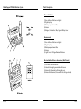
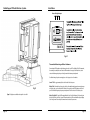
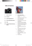
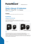
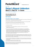
RadioPopper PX CE Radio Wireless
Owners Manual
Table of Contents
RadioPopper is owned by Leap Devices, LLC in Vancouver, WA. This
product was designed, produced, and manufactured in the USA.
TECHNICAL & REGULATORY NOTICE:
Frequency: DSSS 868.000 MHz - 868.600 MHz
Power & Duty Cycle: Less than or equal to 25 milliwatts, duty cycle less than or equal to 1%.
PRODUCT PATENT(S) PENDING
RadioPopper PX CE Transmitter
RadioPopper PX CE Receiver
Brand Name: RadioPopper
Manufactured By: Leap Devices, LLC, Vancouver WA, USA
Introduction . . . . . . . . . . . . . . . . . . . . . . . . . . . . . . . . . . . . . . . . . . . . . . . . . . . . .
4
Specifications and Warnings . . . . . . . . . . . . . . . . . . . . . . . . . . . . . . . . . . . . . . .
6
* A camera shutter should not be activated more than 720 times per hour while a PX
Transmitter is powered on and attached to the master flash device to ensure a 1%
transmission duty cycle is not exceeded per regulatory requirements.
Parts Descriptions . . . . . . . . . . . . . . . . . . . . . . . . . . . . . . . . . . . . . . . . . . . . . . . .
8
Installation . . . . . . . . . . . . . . . . . . . . . . . . . . . . . . . . . . . . . . . . . . . . . . . . . . . . .
10
* The PX Receiver CE is a category 3 device per EN 300 220-1 [4.1.1]
Menu Quick Reference . . . . . . . . . . . . . . . . . . . . . . . . . . . . . . . . . . . . . . . . . . .
14
Operating Instructions . . . . . . . . . . . . . . . . . . . . . . . . . . . . . . . . . . . . . . . . . . .
17
Trouble Shooting . . . . . . . . . . . . . . . . . . . . . . . . . . . . . . . . . . . . . . . . . . . . . . . .
20
EU Declaration of Conformity . . . . . . . . . . . . . . . . . . . . . . . . . . . . . . . . . . . . .
25
Limited Warranty . . . . . . . . . . . . . . . . . . . . . . . . . . . . . . . . . . . . . . . . . . . . . . .
26
This product has been tested and found to conform to R&TTE
Directive 1999/5/EC on basis of conformance with:
EN 301 489-1:2008, EN 301 489-3:(2002-08)
EN 300 220-1:2006, EN 300 220-3:(2000-09)
EN60950-1:2001, EN60825-1:2001
This product is labelled in accordance with European Directive
2002/96/EC concerning waste electrical and electronic equipment
(WEEE). The Directive determines the framework for the return
and recycling of used appliances as applicable throughout the European Union. This label is applied to various products to indicate
that the product is not to be thrown away, but rather reclaimed
upon end of life per this Directive.
This product is RoHS compliant.
Copyright 2007-2010, Leap Devices LLC, All Rights Reserved
Leap Devices LLC, 501 SE Columbia Shores Blvd Suite 100, Vancouver, WA 98661
Page 2
RadioPopper PX CE User Manual - Rev 3.5
PX Transmitter Firmware Version 8-14
PX Receiver Firmware Version 8-10
Page 3
RadioPopper PX Radio Wireless System
Introduction
Introduction
How It Works
Thank you for your purchase of the RadioPopper PX wireless radio
system. We hope you’ll find this system to be a valuable tool in your
creative lighting, giving you flexibility and control never before
possible.
The RadioPopper PX system is beautifully simple. Quickly mount the
PX Transmitter to your Master flash or Commander Unit, a PX Receiver
to each slave flash. Your current master and slave wireless flash system
continues to function just as it always has, minus the line of sight
limitation.
The RadioPopper PX system allows you to use the automatic and
high-speed sync functions built into your existing flash units without
concern of whether or not the master and slave units can “see” each
other. You now have the ability to place your lights wherever you
choose, then controlling the output power of each slave flash from the
camera body manually or automatically via your camera’s ETTL or iTTL
logic system. It’s also the world’s first product to effectively provide
you high speed sync by radio. Enjoy.
Please read this short manual entirely before installing or operating
your RadioPopper PX wireless system. Proper installation is key to
correct operation.
If you have any troubles along the way, feel free to call or email.
360.713.0776
[email protected]
The RadioPopper PX Transmitter “listens” to the light signal being
created inside the master flash unit or remote commander on your
camera’s hot shoe. The PX Transmitter sends this signal by radio where
it is read by the RadioPopper PX Receiver. The receiver then uses it’s
own internal light source to “reproduce” this light signal. The light is
emitted through a window on the back of the Receiver unit directly
into the infrared sensor on a slave flash, that slave flash responds to the
“reproduced” light signal just as it normally would had it seen the light
directly from the master flash.
Installation is easy. Just place the RadioPopper PX Transmitter on top
of your master flash or IR commander device using the included Velcro
pads. “Look Ma! No wires!”
On the receiving end, assemble the mounting bracket for your specific
slave flash. Then simply drop the PX Receiver into the mounting
bracket. No wires or adaptors and no complicated system to re-learn.
Now just power up and shoot. You’ve got remote control of your slave
flashes, full ETTL and iTTL support along with high speed sync all the
way to 1/8000, by radio.
Page 4
Page 5
RadioPopper PX Radio Wireless System
Specifications and Warnings
Compatible Hardware:
WARNING!!! WARNING!!! WARNING!!!!
The PX System has been tested and found to be compatible with the following flash hardware. See our website for
updates as we test and certify compatibility with additional hardware.
Canon Master / Commander Devices:
SpeedLite Transmitter ST-E2, SpeedLite 580EX II, SpeedLite 580EX, Speedlite 550EX II SpeedLite 550EX
Canon Slave / Remote Devices:
SpeedLites 580 EX II, 580EX, 550EX II, 550EX, 430EX, 420EX
Nikon Master / Commander Devices:
SB-900 AF Speedlight, SB-800 AF Speedlight, SU-800 Wireless Speedlight Commander, Nikon “pop-up” flash used as a
Commander(1)
Nikon Slave / Remote Devices:
SB-900 AF Speedlight, SB-800 AF Speedlight, SB-600 AF Speedlight
Note(1): Be sure to order the PX Transmitter Nikon Hot Shoe Pop-Up Flash Adapter for proper mounting
Specifications:
Both PX Transmitter and PX Receiver have similar specifications as follows.
Dimensions : 2.0” x 2.0” x 0.8” (50mm x 50mm x 20mm)
Weight: 2.0 ounces / 60 grams (Including battery and antenna during normal operation)
Battery: Two “AAA” Sized Standard Batteries / Alkaline, NiCad, or NiMH / 0.9 volt to 1.6 volt
Battery Life: Approx 25 Hours continual active transmit time for Std Alkaline battery.
Radio Frequency: 868-868.6 Mhz, <25 mW, <1% Duty Cycle
Radio Range: 300 ft to 1750 ft depending on conditions and environment(2)
Note(2): Please refer to the section “Maximizing Radio Performance” (Pg. 22) in this manual for more information.
Page 6
PLEASE read this section in detail for important warnings and notices.
USE ONLY THE SUPPLIED TRANSMITTER ANTENNA!
Using any antenna other than the one supplied for use with your PX Transmitter is a violation of Federal Law and may actually
cause damage to the radio inside the transmitter. This will also promptly void your warranty. Your PX Transmitter has been
carefully tuned to broadcast the maximum signal strength allowable by law. Altering the antenna characteristics is more
likely to “de-tune” or degrade performance than to improve it.
INSERT THE BATTERY IN THE CORRECT DIRECTION!
Inserting the batteries “backwards” could possibly damage the electronic components inside PX Transmitter and PX Receiver
units. The little “bump” on the AAA always points away from the spring. A graphic is provided at the base of the AAA battery
holder, as well as on the back side of the circuit board for reference. Further, you should observe for the Green Power LED
blinking a few times about one second after you insert the battery - indicating proper insertion.
DO NOT REMOVE OR TAMPER WITH THE CIRCUIT BOARD!
Some of the components inside your PX Transmitters and PX Receivers are especially susceptible to electrostatic shock (they’re
easily ‘zapped’ by static electricity) - just touching them could damage them. Your circuit board is grounded to the case - as
long as it’s not removed everything is safe. Breaking the glue seal and removing or tampering with your circuit board will
promptly void your warranty.
YOUR POPPERS CAN’T SWIM!! KEEP THEM DRY!!
The new splash-proof design of the PX goes a long way to keeping the wet stuff out. However, they are *not* “waterproof”.
Don’t use them outside in the rain, to photograph objects under water, or in any other environment that may allow water to
enter the physical enclosure or battery area.
If you dunk them, it may be too late. Should you do manage to expose a RadioPopper to anything wet, remove the batteries
as quickly as possible and allow it 24 hours to dry. You may find it has come back to life. Allowing anything wet inside the
case of your PX Transmitter or PX Receiver will promptly void the warranty.
CONTACT US IF YOU GET CONFUSED!
You’re a valued customer and we really do care about you. (And not in that automated “your call is very important to us
but we’re going to leave you on hold for an hour anyway” customer service recording sort of way). Seriously, if you’ve got
questions, we’re going to do everything possible to take care of you as quickly and as personally as possible. The phone
number is on our website and you can always email us at [email protected]
Page 7
RadioPopper PX Radio Wireless System
Parts Description
Transmitter Parts
1) User Interface - Buttons and Lights
2) Digital Display
3) Battery Compartment Door
4) Antenna
5) Magnetic / Inductive / Magic Signal Pickup Sensor
Receiver Parts
1) User Interface - Buttons and Lights
2) Digital Display
3) Battery Compartment Door
4) Antenna
6) Light Source - IR Signal Emission Window
Also Included in Kit or as Accessories (Not Pictured)
1) Your first set of AAA Batteries
2) Industrial strength genuine Velcro fasteners
3) Antenna for Transmitter (the straight one)
4) Antenna for Receiver (the one with the 90 degree bend)
Page 8
Page 9
RadioPopper PX Radio Wireless System
Installation
Installation: RadioPopper PX Transmitter
Installation: RadioPopper PX Receiver
1) Remove the battery compartment door on the top side of the unit.
2) Remove the cover and insert two (2) AAA size batteries into the battery holder. It is very important to follow the
polarity direction indicated on the inner sticker to ensure unit operation and avoid possible transmitter damage.
3) Replace the battery compartment door. Once batteries are inserted, the battery door should fit snug.
4) Select the approximate mounting location on top of your Master Flash or IR Commander (supplied by your camera
manufacturer). Ensure this area is clean.
NOTE: It is extremely important that your PX Receiver be mounted in such a way that the
IR light sensor on your Slave flash unit cannot “see” the control signals being sent
by your Master flash unit. The Slave flash must only see the light control signals
being emitted by the light source behind the green circle window on your PX Receiver. The following steps will insure proper mounting and error free operation.
1) Remove battery compartment cover and insert batteries, just as you did with the PX Transmitter. Replace the
battery compartment cover.
5) Attach the Velcro pieces together. Remove both backing sheets and affix the joined Velcro strips first to the under
side center of the PX Transmitter unit. We recommend placing the “rough” hook side of the Velcro against the transmitter, and the soft side of the Velcro against your flash or IR commander.
2) Your included PX Receiver bracket will come disassembled in two separate pieces. You will notice that your
mount can be assembled to match various applications depending on which specific flash you are using. Locate the
appropriate notch on the cradle and slide it into place on the base mount. Ensure that the cradle has the support clips
facing outward as shown in Figure 1.1 on page 12.
6) Hold the PX Transmitter with Velcro attached over the approximate mounting location on the intended Master flash
unit. Compare location to the picture in Fig 2.1 on page 13. Press down firmly and hold pressure for thirty seconds to
tightly bond the Velcro strip adhesive to both the Master flash unit and the under side of the PX Transmitter.
3) Install the supplied antenna (the one with the 90 degree bend) by screwing it onto the antenna connector on the
face of the PX Receiver.
7) Do not pull the Velcro apart for several hours. The adhesive on the Velcro will set to full strength in 20 to 30 hours.
Care should be taken during this time to avoid upsetting the bond being formed between the Velcro and plastic to
ensure maximum long term adhesion.
8) Install the supplied antenna (the straight one) by screwing it onto the antenna connector on the face of the PX
Transmitter.
WARNING: Do not power up the PX Transmitter without the antenna installed - doing so could damage the output
stage of the radio transmitter.
WARNING: Use only the supplied antenna on the PX Transmitter. Using any other antenna is a violation of Federal
Law, and may actually cause damage to the output stage of the radio transmitter.
4) Insert the PX Receiver into the PX cradle so that the optical port is aligned with the hole.
5) Slide your your off-camera flash into the base of your assembled bracket. Remember to lock your flash into place.
Also, take care to align the hole in the foam ring with the light sensor on your slave flash. The foam ring should fully
touch your slave flash in every direction with no gaps. This will ensure your Slave flash unit will only “see” the signals
produced by the PX Receiver, and will not see the signals being sent directly from your Master flash if you are shooting
from a position significantly close to your Slave flash unit(s).
NOTE: The large red transparent piece on the front of your flash is NOT the infrared sensor. In
fact this area has nothing to do with the wireless communication system - it is simply a focus
assist light. The correct sensor is a shiny dark black window on the outside of your slave flash unit.
9) When mounting the PX Transmitter in the future by pressing the Velcro pads together - a greater bond may be
achieved between the Velcro hook and latch sides by pressing firmly, then applying a slight rotational force between
the Master flash unit and the PX Transmitter. This tends to “set” the Velcro pads together.
Page 10
Page 11
RadioPopper PX Radio Wireless System
Installation
Master Flash Light Output
SPEEDLITE
580EX
Fig 2.1
Transmitter Mounting on Other Hardware
For mounting the PX Transmitter on other hardware such as the Canon ST-E2 and Nikon SU-800 IR Commanders,
the mounting is essentially the same. Mount the PX Transmitter to the very top of the Master device, about
centered with the magnetic pickup sensor facing forward and the antenna pointed upward.
For additional images of product mounting, please see the Support section of our website.
Canon ST-E2: We suggest mounting Velcro to the front side of the battery cover.
Fig 1.1
Figure 1.1 displays an assembled bracket setup for a Canon flash
Page 12
Nikon SU-800: Mount directly on the top edge, which is a bit rounded but with proper placement and pressure
on the Velcro pads, a good anchor should be achievable. You may also place the PX Transmitter on the front of
your SU-800 with the magnetic pickup sensor pointed upward. Velcro the unit to the SU-800 battery door.
Nikon “Pop-Up Flash”: Using the PX Transmitter Nikon Hot Shoe Pop-Up Flash Adapter (Sold Separately) simply slide it into the hot shoe. Next, clip your PX Transmitter into the top of the mount with the magnetic pickup
sensor facing forward. Ensure that your Commander mode is activated on your camera.
Page 13
RadioPopper PX Radio Wireless System
Menu Quick Reference
Operation: RadioPopper PX Transmitter - QUICK REFERENCE
Power On / Off - Press and hold the Power Button for one second. Green LED on indicates “power on”, Green LED off
indicates “power off”.
Enter Menu Mode - Tap the “X” button one time to enter Menu Mode. Once in Menu Mode, you will move to the
next menu each time the “P” button is pressed, and you will adjust the setting of the current menu by pressing the “X”
button.
IMPORTANT NOTE!!! When in Menu Mode, the radio will not be active for normal operation. If you attempt to
activate the system by taking a shot on your camera while in Menu Mode, the PX Transmitter will not send any radio
signals. Similarly, the PX Receiver will not receive or respond to any radio signals while in Menu Mode. Taking a shot
while in Menu Mode on the PX Transmitter will cause the menu to cycle off. All settings will be saved, and the radio
will automatically resume normal operation. The PX Receiver will NOT automatically exit the menu.
PX Transmitter Menu Quick Reference
X
P
P
P
Solid Green LED - Unit is powered on. This LED will blink momentarily during the activation of each shot.
Slow Blinking Green LED - This is an indication that your batteries are extremely low such that the PX unit can no
longer operate. The unit will power down. You may observe this auto power down at battery meter levels of 2 or less.
b = Battery Level (9-1)
X
Quickly Exit Menu
G1 = Group 1 Level (00-32)
X
1st Press: Show Current (no change); Subsequent: Adjust Level
Reduce level by pressing the “P” button while holding “X” button.
G2 = Group 2 Level (00-32)
X
1st Press: Show Current (no change); Subsequent: Adjust Level
Reduce level by pressing the “P” button while holding “X” button.
G3 = Group 3 Level (00-32)
X
1st Press: Show Current (no change); Subsequent: Adjust Level
Reduce level by pressing the “P” button while holding “X” button.
CH = Radio Chan (01-16)
X
1st Press: Show Current (no change); Subsequent: Cycle Channels
H = Hardware Mode (C, n)
X
Cycle Hardware Brand Mode - “C” = Canon Gear, “n” = Nikon Gear
L = Light Bright Level (1-5)
X
Cycle Levels - See result in Power light brightness
F = Feedback Mode (1-3)
X
Cycle - 1=Normal (strobe light on shot); 2=High Speed (no light)
P
P
Indicator Lights - Your PX Transmitter and PX Receiver units provide various feedback and status information via the
Power LED (Green) and Link LED (Yellow).
Enter Menu
P
P
X Hold 5 Sec
P
r E = Reset Defaults
P
Exit Menu - Resume Normal Operation
Resets factory default settings. Displays firmware version on startup.
Strobing Yellow LED - The unit strobes the yellow Link light after the radio sends or receives each successful shot. This
strobing is also an indication that the internal computer has received the expected status signals from the internal
radio circuitry. The unit is properly reset after power-up, after leaving the Menu Mode, or after a successful shot.
NOTE: The strobing yellow LED confirmation following each shot is DISABLED in Feedback Mode 2.
Page 14
Page 15
Menu Quick Reference
RadioPopper PX Radio Wireless System
Operational Features
PX Receiver Menu Quick Reference
X
Enter Menu
b = Battery Level (9-1)
X
Quickly Exit Menu
CH = Radio Chan (01-16)
X
1st Press: Show Current (no change); Subsequent: Cycle Channels
Group Selection (G1, G2, G3)
X
1st Press: Show Current (no change); Subsequent: Adjust Level
Reduce level by pressing the “P” and “X” button down together
H = Hardware Mode (C, n)
X
Cycle Hardware Brand Mode - “C” = Canon Gear, “n” = Nikon Gear
L = Light Bright Level (1-5)
X
Cycle Levels - See result in Power light brightness
F = Feedback Mode (1-3)
X
Cycle - 1=Normal (strobe light on shot); 2=High Speed (no light)
P
P
P
P
P
Battery Level Indicator
On both the PX Transmitter and PX Receiver, a two stage battery level indication system is provided. The battery level
may be checked by tapping the “X” button from normal operation. This enters the menu system, the first screen of
which displays the current battery level. “b9” indicates fresh batteries. “b0” indicates dead batteries.
X Hold 5 Sec
P
r E = Reset Defaults
P
Exit Menu - Resume Normal Operation
Resets factory default settings. Displays firmware version on startup.
You may quickly exit the menu by once again tapping the “X” button. This makes for quick and easy battery level
checks by tapping the “X” button twice in a row from normal operation.
A second internal battery level check is performed when inserting new batteries, on powering up the unit, and at
regular intervals. This internal level check insures the power regulators have enough battery level remaining for
normal operation. Once the unit can no longer reliably maintain minimum power level, the Power LED will blink
slowly, then the unit will power down indicating dead batteries which must be changed. This automatic low power
down may occur at any battery level less than “b2” on the battery level indicator.
You may also use rechargeable batteries in your PX units. Rechargeable batteries provide a slightly lower voltage - this
is fine for operation, but you will note a fresh set of rechargeable batteries will not produce a battery level of 9 even
when fully charged. This is normal.
Group Power Levels (G1, G2, G3) The Group Power Level setting allows you to manually and remotely control the power output level of various other
compatible devices. The RadioPopper JrX Receiver Studio provides the ability to manually adjust the power level of
Alien Bees and White Lightning brand studio units. Other future devices may also make use of this setting. Please
refer to the JrX Receiver owner’s manual for more details.
The three groups may be adjusted independently. To see what the current setting is without changing it, tap the “X”
button one time. To increment the level up, press and hold the “X” button. To reduce the level, press the “P” button
while holding the “X” button and the numbers will count down in reverse. It is recommended to use two hands or both
thumbs for this operation.
The level goes from 00 to 32 and does not automatically loop. A zero level “00” will *disable* that particular group
from activating at all. This makes it easy to remotely turn entire banks of studio lights on and off. Level 01 is
minimum, 32 is the maximum level of your device.
Each time the level ticks up or down, the radio transmitter sends a quick transmission with the new levels. All remote
controlled equipment on the current radio channel is instantly set with the new values. You can actually observe the
model lamp level of compatible studio lights rise and fall as the level for that particular group is ticked up or down.
Page 16
Page 17
Operating Instructions
Radio Channel Selection - (CH)
Your PX units provide 16 individual channels. Multiplied by the four channels of your existing flash system, this
provides an effective 64 distinct operating channels. Increment the channel number by tapping the “X” button.
Channels go from 01 to 16, then back to 01.
Set your PX Transmitter and all PX Receivers to the same radio channel.
VERY IMPORTANT: You must exit the menu system before your devices will operate normally.
Hardware Mode - (H)
To provide maximum flexibility and scalability, the PX units have being designed using completely separate internal
computer “programs” for handling each type of camera gear. These programs are tailored to best handle the different
“language” of control signals sent by various camera hardware. The current firmware provides full support for Canon
and Nikon hardware.
Tap the “X” button to cycle hardware modes. Set the default “C” for Canon hardware, and “n” for Nikon hardware.
Light Bright Level - (L)
The electronics, computer processor, and radio unit designed into the PX units are so efficient, that they actually draw
less power from your battery than a single LED light. It turns out that the Power LED is the most significant draw of
battery power.
Battery life can be significantly extended if the LED’s are dimmed. Additionally, you may find yourself photographing
in very dark environments where bright indicator lights may be a distraction.
The indicator lights may therefore be adjusted to one of five values. Tap the “X” button to cycle through the levels. The
lights will instantly adjust to the new level.
Feedback Mode - (F)
Your PX units provide several different types of user “feedback” following each shot. Tap the “X” button to cycle modes.
RadioPopper PX Radio Wireless System
Operational Features - Con’t.
F2 - No feedback is provided. The PX unit will quickly cycle following a radio transmission and ready for another shot.
This makes possible using the high speed shutter built into many camera systems. The PX units will easily keep up if
you are shooting 8 frames per second or higher while in this mode.
F3 - Diagnostic Mode. This mode is intended for testing and verification of proper unit operation. In this mode, after
each shot, the PX Transmitter will display a number representing the number of individual data bits observed from
your Master flash device. About a half second following, all PX Receivers will display the number of data bits decoded
from the radio signal and blinked out the light source inside the PX Receiver.
For proper operation, the PX Receiver(s) should always display the same F Mode number displayed by the PX
Transmitter. On each given shot, if these numbers are equal, it is an assurance the the PX units are functioning
correctly and with zero data errors. If it is observed these numbers are equal and your flash devices are not functioning
correctly, please double check the settings in your camera flashes, insure the correct Hardware mode is set in your PX
units, and double check the installation of the PX units on your Master and Slave flash devices.
Note it is normal that the computed numbers differ slightly from shot to shot as your flashes don’t always send the
same number of blinks. It is only important for purpose of this mode that the numbers match between PX Transmitter
and PX Receiver(s) on each individual shot.
Reset Defaults - (r E)
Your PX units may be completely reset to factory defaults using this mode. The reset will also invoke the factory
pre-test start sequence the next time your unit is powered on. To invoke the Reset to take place, press and hold the “X”
button. A time out will count backward for 5 seconds to zero. At zero the unit will blank the display, both LED lights
will strobe during the reset. The unit will then power down.
The reset is completely non destructive and may be performed at any time. During the reset, the PX unit will reset
Radio Channel 1, Canon Hardware Mode, Normal Feedback Mode, and will zero the Group Level settings.
The next time the unit is powered on, the factory pre-test will take place. During this test, the current unit firmware
version is displayed in the format, for example, “8 -” , then “14”. This would indicate firmware version 8-14.
F1 - The default. After each shot you will see the Link LED strobe momentarily. On the PX Transmitter this indicates a
signal was observed from your Master flash device and sent by radio. On the PX Receiver, this indicates the radio has
observed and decoded a radio transmission.
Page 18
Page 19
Trouble Shooting
RadioPopper PX Radio Wireless System
About This Section
We have put much consideration into the design and operation of the PX system. We are confident you will experience
simple and worry free operation. Please refer to this section if you do experience any trouble while operating your PX’s.
This section is split into three segments focused on the types of mis-fire or malfunction issues you are likely to encounter.
Smart PX Units
Your RadioPopper PX units have been designed with some of the most advanced digital radio technology available. The
radio system itself includes significant error correction and background signal rejection technology. Additionally, the
computer and operating system of the PX units actually understand the information being sent and processed by your
flash units. The overall design makes for a very robust, reliable, and long range radio system.
The PX units include various feedback and diagnostic features which make it easy for you to determine if the PX units
themselves are functioning normally.
Once the PX units are properly installed and your flash units are themselves properly configured, you should experience
solid and reliable operation of your flash system - even at long ranges.
PX System Trouble Shooting
6) Shoot and observe the Link LED strobes momentarily following the shot on both the PX Transmitter and all PX
Receiver units. This is an indication that a radio transmission packet was sent and properly received by each PX unit.
Occasionally, the Link LED may not strobe on PX Receivers if the PX Transmitter is placed extremely close to the PX
Receiver. The new digital radio modulation used by the PX system is quite powerful, and the PX Receiver is extremely
sensitive. At very close range (within 12 inches or so) the PX Transmitter may “over-drive” the radio of the PX Receiver.
This will not damage the units, but it may prevent the radio packet from being clearly received. Perform all testing
within a few feet of separation between units.
7) You may optionally set Feedback Mode (F) to 3 on all units. In this mode, the PX Transmitter will show the number of
data bits sent on the display. Each PX Receiver will then display the number of data bits received. These numbers should
be the same for each individual shot. (They may be different numbers from shot to shot - this is perfectly normal).
8) Finally, you may reset the factory default settings of your PX units. Tab to the Reset menu (r E), press and hold the “X”
button for 5 seconds to initiate the reset. The next time your unit powers on, it will completely check itself and display
any hardware errors which may be present (the unit would begin blinking “E “ followed by a number on the display).
You should observe the software version, followed by a segment test of the display “88”, then power off. The LED lights
should gradually gain then dim in brightness.
Let’s first make sure your PX system is operating properly.
If these tests are complete with expected results, then any issue is most certainly related to either the installation of the
PX units on your Master and Slave flash devices, or the configuration of your flash units themselves.
1) The PX Transmitter will not send any radio information while in the Menu mode. If your PX Transmitter does observe
you have taken a shot while in Menu Mode, it will immediately save your settings and exit back to normal operation, so
any follow-up shots should be transmitted normally.
Flash Unit Configuration - Trouble Shooting
2) The PX Receiver however will not automatically drop out of Menu Mode. If you have just set a channel for evaluation
or changed a setting, then attempted to activate a test shot while the menu is still displayed on the PX Receiver, the unit
will not activate. You must exit the menu before your PX Receiver can resume normal operation.
3) Clear Menu Mode by tapping the “P” button to tab through the menus. After the “r E” menu, your unit should resume
normal operation. Observe for the yellow LED to strobe at this point. This confirms the radio system is operating and is
ready to transmit or receive a signal.
Once you’re sure your PX units are properly installed and operating normally, please check that your actual flash units are
properly configured for wireless flash operation.
1) Remove the PX Receiver from your Slave flash. Place your Slave flash such that it has a clear line of sight to the Master
flash on your camera, at a range of 3 to 5 feet. Now attempt to operate your flash system using the “line of sight” IR
system already built into the flashes. Your Slave flash should activate reliably and as expected at this time. If your Slave
flash does not operate as expected, then your Master and Slave flash units themselves are not properly configured.
2) Set the flash on your camera as “Master”, and set all of the remote wireless flashes to “Slave” or “Remote”.
4) Make sure all PX units are set to the same radio channel. Tab to the “CH” menu by tapping the “P” button. Then press
the “X” button *one* time to display the current radio channel without actually changing it. To modify the channel
values, use the “X” button to reach the desired channel.
3) Ensure Master and Slave flash units are both set on the same ETTL/iTTL. This channel is not related to the Radio
Channel set in your PX units.
5) Ensure the proper Hardware Mode is set. The default mode is Canon. Set the “H” menu from “C” to “n” if you are
shooting Nikon gear.
4) If your flash units still do not operate, even without the PX units installed, please consult the owner’s manual supplied
with your particular brand and model of flash units. Refer to the manual’s section regarding wireless operation.
Page 20
Page 21
Trouble Shooting
PX Installation Trouble Shooting
Now let’s check the physical installation of your PX units on your Master and Slave flash unit(s).
1) On your Master flash, PX Transmitter should be oriented such that the small “bump” on the front (the signal pickup
sensor) is facing the same direction as the direction of light coming out of the flash. Please refer to Fig. 2.1, Page 13.
2) Make sure the window with the green circle on your PX Receiver (on the back side) is pointing directly into the signal
sensor of your slave flash. The proper location of this sensor is noted by the opening in the sticker supplied with Canon
mounting kits. On Nikon flash units, the IR sensor is the small black circle / window next to the battery door on your
flash. THE RED WINDOW ON THE FRONT OF YOUR FLASH IS _NOT_ THE IR SENSOR. The red window emits a focus assist
light and does not interact with the wireless flash function in any way.
3) For Canon mounting kits, be sure to remove the white center of the circle punched in the sticker. This center dot
should not be applied to the flash as it would block the signal from entering the flash.
PX Burst Mode and Crossed Signals
The PX system operates by “burst” radio transmission. Essentially, the PX Transmitter waits for a data signal to begin
emitting from your Master flash device. It then begins transmitting a packet of radio data including some coding used to
identify the signal and provide error correction. The PX Receiver sees this communication and begins to process it.
This processing time is extremely short, but it does cause the “Morse Code” blinks of light being reproduced by the PX
Receiver to emit very slightly delayed. If your Slave flash is able to “see” the line of sight IR signal coming from your
Master flash directly, then “sees” the signal being produced by the PX Receiver very slightly following, it may see two
copies of the same signal, slightly out of time with each other.
The PX Transmitter and PX Receiver are “smart” enough to quickly adjust this timing delay and catch the signal back up
to real time such that they are both perfectly in timing sync with each other before any instruction is given to actually
make light. Therefore, this timing delay has absolutely no effect on the timing of the pre-flash, ETTL/iTTL exposure
evaluation, high speed sync function, or the timing of the actual flash.
This Burst Mode makes it possible for multiple photographers to now control the same Slave flash unit in any of its
modes, as well as providing robust error correction, and it has no effect what so ever on the actual operation of your
wireless system. However, care must be taken in the mounting of your PX Receiver to your Slave flash to ensure reliable
operation.
RadioPopper PX Radio Wireless System
1) Apply the foam ring supplied with your mounting kit to your PX Receiver around the window on the back of the
receive marked by the green circle. This foam ring exists to seal the slight gap between the PX Receiver and your slave
flash so that outside light signals do not enter the light sensor of your slave flash.
2) Try moving the Slave flash significantly out of view of the Master flash - place it in another room or down a hall and
attempt to operate the system. If your Slave flash operates reliably when significantly out of view, then becomes erratic
the same room or small space, then check there are no gaps between the PX Receiver and the light sensor of your slave
flash.
3) Regarding Nikon SB-900, SB-800, and SB-600 Speed Light units: In these units, the physical internal space of the
flash is somewhat open, such that light coming in through the red focus assist window may reflect around the inside of
the flash and still reach the wireless light sensor from the inside. When properly mounted, interference due to crossed
signals is rarely observed and only at close range. If your situation does require placing the Slave flash at close range and
oriented such that the red focus assist window is pointed directly at the Master, place a piece of tape covering the red
window entirely. This will eliminate any light leakage internal to the flash and will allow reliable operation even at very
close ranges.
Additional Support
If you have any questions, concerns, or issues not resolved by this Trouble Shooting section, we absolutely encourage
you to contact us directly. We are happy to assist. In nearly every situation, we are able and happy to resolve any
configuration or setup issue via email or with a short phone call.
Online Support:
radiopopper.com/support
Email:
[email protected]
Phone:
360.713.0776
Once your PX Receiver is properly mounted, this should not be an issue. It is generally only observable when shooting
the Master flash directly into the Slave flash at very close range, thus it is not a concern in normal operation.
Page 22
Page 23
Trouble Shooting
Leap Devices, LLC
dba RadioPopper
501 SE Columbia Shores Blvd Suite 100
Vancouver, WA 98661
www.radiopopper.com
Kevin J. King
Director of Engineering
Tel: +1 360 713-0776
Canon is a registered trademark of Canon Inc. in the United States and may also be a registered trademark or trademark in other countries. ITTL stands for
Intelligent Through The Lens, the trade-marked name for Nikon’s exposure measurement system on SLR cameras. Nikon is a registered trademark of Nikon
Corporation. All other product and brand names are trademarks of their respective owner.
Page 24
Page 25
Limited Warranty
LIMITED WARRANTY The Limited Warranty set forth below is given by Leap Devices LLC (hereafter “Leap”) in the United States with respect to the RadioPopper PX Transmitter
and / or RadioPopper PX Receiver packaged with this Limited Warranty and identified by model number within this Limited Warranty (each a “Product”)
when purchased and used in the United States or in Canada.
This Limited Warranty is only effective upon presentation of this warranty card and proof of purchase.
A Product, when delivered to you in new condition in its original container at the point of it’s initial retail sale, is warranted against defects in materials
or workmanship as follows: for a period of one (1) year from the date of original purchase, defective parts or a defective Product returned to Leap or
its authorized service providers, and proven to be defective upon inspection, will be repaired with new or comparable rebuilt parts or exchanged for a
refurbished Product, as determined by Leap or the authorized service provider, in their sole discretion. Replaced parts and exchanged Products will become
the property of Leap.
When returning a Product for warranty service, the shipping charges must be prepaid and the Product should be shipped in its original container, or an
equivalent, properly packaged container to withstand the hazards of shipment and fully insured. A copy of this warranty card and proof of purchase should
be enclosed, as well as a description of the problem. Repairs will be made and the Product will be returned, shipped at NO CHARGE, within the country of
repair. The Product must be received for warranty service by Leap before the expiration of this Limited Warranty. This warranty only covers defective materials or workmanship encountered in normal use and service of a Product and does not apply in the following
cases:
(a) If a circuit board is removed from the plastic enclosure for any reason or if the original factory glue seal between the circuit board and plastic enclosure
is disturbed in any way. Tampering with or removing the circuit board from the enclosure VOIDs this warranty.
(b) Loss or damage due to neglect and/or abuse causing deterioration, mishandling, accident or failure to follow operating instructions including but not
limited to operation of a PX Transmitter with no antenna attached, or operation with an antenna other than that provided with the product originally, or
inserting the batteries backward for any length of time.
(c) If a Product is defective as a result of leaking batteries or damage due to water or other liquid, or any environmental conditions.
(d) Defective materials or workmanship where the defect is due to a Product having been serviced or modified by other than Leap or a Leap authorized
service provider.
(e) Malfunction resulting from the use of accessories, attachments, supplies, parts or devices (including, without limitation, batteries) that do not conform
to Leap specifications.
(f) Damage resulting during shipment. (Claim must be presented to and examined by the shipper).
(g) Damage or service resulting from modifications or alternations to a Product in any way (including any alteration or removal if its serial number or
identification marks).
NO IMPLIED WARRANTY, INCLUDING ANY IMPLIED WARRANTY OF MERCHANTABILITY OR FITNESS FOR A PARTICULAR PURPOSE, APPLIES TO A PRODUCT
AFTER THE APPLICABLE PERIOD OF THE EXPRESS LIMITED WARRANTY STATED ABOVE, AND NO OTHER EXPRESS WARRANTY OR GUARANTY, EXCEPT AS
MENTIONED ABOVE, GIVEN BY ANY PERSON OR ENTITY WITH RESPECT TO A PRODUCT SHALL BIND LEAP (SOME STATES AND PROVINCES DO NOT ALLOW
LIMITATIONS ON HOW LONG AN IMPLIED WARRANTY LASTS, SO THE ABOVE LIMITATION MAY NOT APPLY TO YOU). LEAP SHALL NOT BE LIABLE FOR LOSS OF
REVENUES OR PROFITS, INCONVENIENCE, EXPENSE FOR SUBSTITUTE EQUIPMENT OR SERVICE, STORAGE CHARGES, LOSS OR CORRUPTION OF DATA, OR ANY
OTHER SPECIAL, INCIDENTAL OR CONSEQUENTIAL DAMAGES (INCLUDING, WITHOUT LIMITATION, ANY LOSS OF FILM OR DIGITAL IMAGE FILES) CAUSED BY THE
USE OR MISUSES OF, OR INABILITY TO USE, A PRODUCT, REGARDLESS OF THE LEGAL THEORY ON WHICH THE CLAIM IS BASED, AND EVEN IF LEAP HAS BEEN
ADVISED OF THE POSSIBILITY OF SUCH DAMAGES. IN NO EVENT SHALL RECOVERY OF ANY KIND AGAINST LEAP BE GREATER IN AMOUNT THAN THE PURCHASE
PRICE OF THE PRODUCT SOLD BY LEAP AND CAUSING THE ALLGED DAMAGE. WITHOUT LIMITING THE FOREGOING, YOU ASSUME ALL RISK AND LIABILITY
FOR LOSS, DAMAGE OR INJURY TO YOU AND YOUR PROPERTY AND TO OTHERS AND THEIR PROPERTY ARISING OUT OF THE USE OR MISUSE OF, OR INABILITY
TO USE, THE PRODUCT NOT CAUSED SOLELY AND DIRECTLY BY THE NEGLIGENCE OF LEAP (SOME STATES AND PROVINCES DO NOT ALLOW THE EXCLUSION OR
LIMITATION OF INCIDENTAL OR CONSEQUENTIAL DAMAGES, SO THE ABOVE EXCLUSION OR LIMITATION MAY NOT APPLY TO YOU). THIS LIMITED WARRANTY
SHALL NOT EXTEND TO ANYONE OTHER THAN THE ORIGINAL PURCHASER OF A PRODUCT, OR THE PERSON FOR WHOM IT WAS PURCHASED AS A GIFT AND
STATES YOUR EXCLUSIVE REMEDY.
Leap Devices LLC, 501 SE Columbia Shores Blvd. Suite 100, Vancouver, WA 98661
Page 26
Copyright 2007-2010, Leap Devices LLC, All Rights Reserved