1
INSTRUCTION
MANUAL
4080 Series
Function and Arbitrary/Function Generators
Model 4084AWG, 4086AWG, 4084, 4085, 4086, 4087
4080 series Arbitrary/Function Generator with Counter –Instruction Manual
Safety Summary
The following safety precautions apply to both operating and maintenance personnel and must be
observed during all phases of operation, service, and repair of this instrument. Before applying power,
follow the installation instructions and become familiar with the operating instructions for this
instrument.
Failure to comply with these precautions or with specific warnings elsewhere in this manual violates
safety standards of design, manufacture, and intended use of the instrument. B&K Precision Corporation
assumes no liability for a customer’s failure to comply with these requirements. This is a Safety Class I
instrument.
GROUND THE INSTRUMENT
To minimize shock hazard, the instrument chassis and cabinet must be connected to an electrical ground.
This instrument is grounded through the ground conductor of the supplied, three-conductor ac power
cable. The power cable must be plugged into an approved three-conductor electrical outlet. Do not alter
the ground connection. Without the protective ground connection, all accessible conductive parts
(including control knobs) can render an electric shock. The power jack and mating plug of the power
cable meet IEC safety standards.
DO NOT OPERATE IN AN EXPLOSIVE ATMOSPHERE
Do not operate the instrument in the presence of flammable gases or fumes. Operation of any electrical
instrument in such an environment constitutes a definite safety hazard.
KEEP AWAY FROM LIVE CIRCUITS
Instrument covers must not be removed by operating personnel. Component replacement and internal
adjustments must be made by qualified maintenance personnel. Disconnect the power cord before
removing the instrument covers and replacing components. Under certain conditions, even with the
power cable removed, dangerous voltages may exist. To avoid injuries, always disconnect power and
discharge circuits before touching them.
WARNINGS AND CAUTIONS
WARNING and CAUTION statements denote a hazard. Follow all instructions contained in these
statements.
A WARNING statement calls attention to an operating procedure, practice, or condition, which, if not
followed correctly, could result in injury or death to personnel.
A CAUTION statement calls attention to an operating procedure, practice, or condition, which, if not
followed correctly, could result in damage to or destruction of part or all of the product.
WARNING:
Do not alter the ground connection. Without the protective ground
connection, all accessible conductive parts (including control knobs) can
render an electric shock. The power jack and mating plug of the power
cable meet IEC safety standards.
WARNING:
To avoid electrical shock hazard, disconnect power cord before removing
covers. Refer servicing to qualified personnel.
CAUTION:
Before connecting the line cord to the AC mains, check the rear panel AC
line voltage indicator. Applying a line voltage other than the indicated
voltage can destroy the AC line fuses. For continued fire protection, replace
fuses only with those of the specified voltage and current ratings.
2
4080 series Arbitrary/Function Generator with Counter –Instruction Manual
Table of Contents
1. PRODUCT INTRODUCTION ................................................................................................5
1.1 Description .......................................................................................................................5
1.2 Key features......................................................................................................................5
2. SPECIFICATIONS ..................................................................................................................6
2.1 Function Generator ...........................................................................................................6
2.2 Universal Counter.............................................................................................................9
2.3 General .............................................................................................................................10
3. PANEL DESCRIPTION ..........................................................................................................11
3.1 Front Panel........................................................................................................................11
3.1.1 Overview of Keys ....................................................................................................11
3.1.2 Display Annunciators ...............................................................................................12
3.1.3 Description of front panel keys ................................................................................13
3.1.3 Description of menu parameters ..............................................................................14
3.2 Rear Panel.........................................................................................................................17
4. OPERATING INSTRUCTIONS..............................................................................................18
4.1 Installation ........................................................................................................................18
4.2 Main operating modes ......................................................................................................18
4.3 Waveform Selection..........................................................................................................19
4.4 Data entry .........................................................................................................................20
4.5 Output Configuration........................................................................................................21
4.5.1 Set Frequency and Period.........................................................................................21
4.5.2 Set Amplitude...........................................................................................................21
4.5.3 Set DC Offset Voltage ..............................................................................................22
4.5.4 Adjust duty cycle......................................................................................................22
4.5.5 Sync/TTL Signal ......................................................................................................23
4.5.6 Signal Store and Recall ............................................................................................23
4.6 Set Modulation and Sweep Parameters ............................................................................24
4.6.1. Sweep mode ............................................................................................................24
4.6.2 FM modulation.........................................................................................................26
4.6.3 AM modulation ........................................................................................................27
4.6.4 Burst modulation......................................................................................................28
4.6.5 FSK modulation .......................................................................................................30
4.6.6 PSK modulation .......................................................................................................31
4.7 Set System Parameters......................................................................................................32
4.8 Universal Counter.............................................................................................................34
5. REMOTE INTERFACE REFERENCE...................................................................................35
5.1 Introduction ......................................................................................................................35
5.2 Overview and syntax of SCPI instructions .......................................................................35
5.3 Detailed description of SCPI Instructions ........................................................................39
6. USER PROGRAMMABLE ARBITRARY WAVEFORM MODULE ....................................47
7. APPENDIX ..............................................................................................................................57
A) Declaration of conformity .................................................................................................58
B) Service and Warranty Information.....................................................................................57
3
4080 series Arbitrary/Function Generator with Counter –Instruction Manual
Intentionally left blank
4
4080 series Arbitrary/Function Generator with Counter –Instruction Manual
1. PRODUCT INTRODUCTION
1.1 Description
The B+K Precision 4080 Series are laboratory grade synthesized function generators with a wide
frequency range of up to 120 MHz. Direct digital synthesis (DDS) techniques are used to create
stable, accurate output signals for clean, low distortion sine waves and an extensive selection of
built-in standard and arbitrary waveforms. The instrument supports AM, FM, FSK, PSK and pulse
modulation and linear and logarithmic sweep. Modulation parameters can be set precisely and are
adjustable over a wide range. The 4080 Series supports internal and external modulation sources as
well as internal, external and gated trigger sources.
All models are capable of generating complex, predefined arbitrary waveforms. Additionally,
models 4084AWG and 4086AWG provide the flexibility to create custom waveforms. The AWG
module includes an intuitive, graphical Windows based software tool for creating and editing
custom arbitrary waveforms and transferring the waveforms to the instrument’s non-volatile
memory. The software also provides a direct interface to Tektronix® TDS1000, TDS2000
TPS2000 and TDS3000 series digital storage oscilloscopes offering users a convenient means to
recreate waveforms originating from the DSO’s display or internal memory.
The 4080 Series front-panel operation is straightforward. Parameters can be entered using the knob
or directly via the numerical keypad and unit keys.
The instruments are fully programmable via the standard RS232 interface. The command set is
SCPI (standard Commands for Programmable Instruments) compatible.
The combination of classical function and arbitrary waveform generator makes this series a versatile
solution for many applications in Electronic Test and Design, Sensor Simulation, Education and
Training.
1.2 Features
•
•
•
•
•
•
•
•
•
•
Direct Digital Synthesis (DDS) architecture
Wide frequency range of 1µHz ~ 120MHz (model 4087, sine wave only)
Clean and stable output of very small signals down to 1mV (50Ω)
27 build-in standard and complex waveforms.
Eight downloadable 16000 point memories for custom arbitrary waveforms (models
4084AWG and 4086AWG only)
Graphical Arbitrary Waveform Generation Software tool for Microsoft® WindowsTM
(models 4084AWG and 4086AWG only)
Convenient data input via knob or numerical keypad.
Bright, easy to read display using VFD (Visible Vacuum Fluorescent) technology
Fully programmable via SCPI compatible command set
100 MHz Universal Counter with frequency measurement and totalize function
5
4080 series Arbitrary/Function Generator with Counter –Instruction Manual
2. SPECIFICATIONS
2.1 Function Generator
Waveform Characteristics
Main Waveforms: Sine, square
Waveform Amplitude resolution: 12 bits
Sample Rate:
200MSa/s (4084, 4084AWG, 4085, 4086, 4086AWG)
300MSa/s (4087)
Sine:
Harmonic Distortion of Sine Wave:
≤ - 50dBc (frequency ≤ 5MHz)
≤ - 45dBc (frequency ≤ 10MHz)
≤ - 40dBc (frequency ≤ 20MHz)
≤ - 35dBc (frequency ≤ 40MHz)
≤ - 30dBc (frequency > 40MHz)
Total Harmonic distortion: 0.1% (20Hz ~ 100kHz)
Square:
Rise and Fall Time of Square Wave: ≤15ns
Note: Test conditions for harmonic distortion, sine distortion, rise/fall time: Output
Amplitude 2Vp-p, Environmental temperature: 25℃±5℃
Build in standard and complex (arbitrary) waveforms:
27 build-in standard and complex waveforms.
Sine, Square, Triangle, Positive Ramp, Falling Ramp, Noise, Positive Pulse, Negative
Pulse, Positive DC, Negative DC, Stair wave, Coded Pulse, Full wave rectified,
Half-wave rectified, Sine transverse cut, Sine vertical cut, Sine phase modulation,
Logarithmic, Exponential, Half-round, SINX/X, Square root, Tangent, Cardiac,
Earthquake, Combination
Waveform Length: 4096 dots
Amplitude Resolution: 10 bits
Pulse Wave:
Duty Cycle:
Rise/Fall Time:
0.1% ~ 99.9% (below 10kHz), 1% ~ 99% (10kHz ~ 100kHz)
≤100ns (Duty cycle 20%)
DC signal characteristics:
DC range:
≤ 10mV – 10V (high impedance)
DC Accuracy:
≤ ±5% of setting +10mV (high impedance)
Module for user defined arbitrary waveform generation (models 4084AWG and 4086AWG only)
Number of memory locations for arbitrary waveforms: 8
Length of waveforms:8~16000 points
Resolution of waveform amplitude:10 bits
Frequency range:100µHz~100kHz
Sample rate:200MSa/s
6
4080 series Arbitrary/Function Generator with Counter –Instruction Manual
Frequency Characteristics
Frequency Range:
Main waveforms (sine, square):
Model 4084/4084AWG: 1µHz ~ 20MHz
Model 4085:
1µHz ~ 40MHz
Model 4086/4086AWG 1µHz ~ 80MHz (sine wave)
1µHz ~ 40MHz (square wave)
Model 4087
1µHz ~ 120MHz (sine wave)
1µHz ~ 40MHz (square wave)
All other waveforms:
All models:
1µHz ~ 100kHz
Frequency Stability:
±1×10⁻⁶ (22℃±5℃)
Resolution:
Frequency Accuracy:
Data entry Units:
1µHz
≤ ± 5×10⁻⁶ (22℃±5℃)
s, ms, Hz, kHz, MHz
Amplitude Characteristics
Amplitude Range:
4084, 4084AWG: 2mV ~ 20Vpp (open circuit), 1mV ~ 10Vpp (50Ω)
4085
4086, 4086AWG: for Freq ≤ 40MHz: 2mV ~ 20Vpp (open circuit), 1mV ~ 10Vpp (50Ω)
for Freq > 40MHz: 2mV ~ 4Vp-p (open circuit), 1mV ~ 2Vpp (50Ω)
4087:
for Freq ≤ 40MHz: 2mV ~ 20Vpp (open circuit), 1mV ~ 10Vpp (50Ω)
for Freq > 40MHz: -76dBm ~ +13.5 dBm(50Ω)or 0.1mV ~ 3Vpp(50Ω)
Max. Resolution:
2µVpp (open circuit), 1µVpp (50Ω)
Amplitude Accuracy:
Amplitude Stability:
± 1%+0.2mV (sine wave relative to 1kHz)
±0.5 % /3 hours
Flatness:
For amplitude ≤ 2Vpp: ±3% (frequency≤5MHz),
For amplitude >2Vpp: ±5% (frequency≤5MHz),
Models 4086/AWG, 4087 only:
±10% (5MHz<frequency≤40MHz)
±10% (5MHz<frequency≤20MHz)
±20% (frequency>20MHz)
±1dBm (frequency>40MHz)
Output Impedance: 50Ω
Output Units:
Vpp, mVpp, Vrms, mVrms, dBm
7
4080 series Arbitrary/Function Generator with Counter –Instruction Manual
DC Offset Characteristics
Offset Range (open circuit)
Freq ≤ 40MHz): ±10Vpk ac + dc (Offset ≤ 2×peak-to peak amplitude)
Freq > 40MHz): ±2Vpk ac + dc (Offset ≤ 2×peak-to peak amplitude)
Resolution:
2µV (open circuit), 1µV (50Ω)
Offset Error: ±5% of setting +10mV (Ampl. ≤ 2Vpp into open circuit)
±5% of setting +20mV (Ampl. > 2Vpp into open circuit)
AM Characteristics
Carrier Waveforms:
sine or square
Carrier Frequency Range:
same as main waveforms
Modulation Source
internal or external
Modulating Waveform:
5 internal waveforms (sine, square, triangle, rising/falling ramp)
Frequency of modulating signal: 100µHz ~ 20kHz
Distortion:
≤ 2%
Modulation Depth:
1% ~ 120%
1% ~ 80% (frequency>40MHz, Ampl > 2Vpp into open circuit)
Modulation Error:
± 5%+0.2%
(100µHz < frequency ≤ 10kHz)
±10%+2%
(10kHz < frequency ≤ 20kHz)
Amplitude of ext. input signal:
3Vp-p (-1.5V~ +1.5V)
FM Characteristics
Carrier Waveforms
sine or square
Carrier Frequency Range:
same as main waveforms
Modulation Source:
internal or external
Modulating Waveform:
5 internal waveforms (sine, square, triangle, rising/falling ramp)
Frequency of modulating signal: 100µHz ~ 10kHz
Peak Frequency Deviation:
Max. 50% of carrier frequency for internal FM
Max 100kHz (carrier frequency≥5MHz) for external FM,
with input signal voltage 3Vp-p (-1.5V~+1.5V)
FSK Characteristics
Carrier Waveform
Carrier Frequency Range:
Control Mode
FSK Rate:
PSK Characteristics
Waveform:
Frequency Range:
PSK:
Resolution:
PSK rate:
sine or square
same as main waveforms
internal or external trigger (external: TTL level, low level F1,
high level F2)
0.1ms ~ 800s
sine or square
same as main waveforms
Phase 1 (P1) and Phase 2 (P2), range: 0.0 ~ 360.0°
0.1°
0.1ms ~ 800s
8
4080 series Arbitrary/Function Generator with Counter –Instruction Manual
Control Mode:
internal or external trigger (external: TTL level, low level P1,
high level P2)
Burst Characteristics
Waveform:
sine or square
Frequency Range: same as main waveforms
Burst Counts :
1 ~ 10000 cycles
Time interval between bursts:
0.1ms ~ 800s
Control Mode:
internal, single or external gated trigger
Frequency Sweep Characteristics
Waveform:
sine or square
Start/Stop Freq.: same as main waveforms
Sweep Time:
1ms ~ 800s (linear), 100ms ~ 800s (log)
Sweep Mode:
Linear or Logarithmic
External trigger signal frequency: DC ~ 1kHz (linear) DC~10Hz (log)
Control Mode:
internal or external trigger
Rear Panel Terminals (for modulation and sweep)
Output MOD OUT
Frequency:
100µHz ~ 20kHz
Waveform:
sine, square, triangle, rising/falling ramp
Amplitude:
5Vp-p ± 5%
Output Impedance: 600Ω
Modulation IN
3 Vpp = 100% Modulation
External Input Trig/FSK/Burst
Level: TTL
Main OUTput
Impedance:
Protection:
50Ω
Short circuit and overload protected
State Storage Characteristics
Storage Parameters:
frequency, amplitude, waveform, DC offset values, modulation
parameters
Storage Capacity:
10 user configurable stored states
Storage Time:
more than 10 years
2.2 Universal Counter
Frequency Range
Frequency Measurement:
Totalize mode:
1Hz ~ 100MHz
50MHz max
9
4080 series Arbitrary/Function Generator with Counter –Instruction Manual
Input Characteristics
Sensitivity
Input attenuator disabled:
Input attenuator enabled:
50mVrms (f: 10Hz ~ 50MHz), 100mVrms (f: 1Hz ~ 100MHz)
0.5Vrms (f: 10Hz ~ 50MHz), 1Vrms (f: 1Hz ~ 100MHz)
Max. Input Voltage Allowed:
100Vp-p (f≤100kHz), 20Vp-p (1Hz~100MHz)
Input Impedance:
R>500kΩ, C<30pF
Coupling:
AC
Waveform:
sine or square
Low Pass Filter:
cut off frequency about 100kHz (with internal attenuation: ≤ -3dB)
with external attenuation: ≥ -30 dB (f >1MHz)
Gate Time Setting:
10ms ~ 10s continuously adjustable
Display Bits:
8 (for gate Time>5s)
Totalize Capacity:
≤ 4.29×10⁹
Control Mode:
manual or external gate control
Accuracy:
time base error ± trigger error (when signal SNR > 40dB,
trigger error ≤ 0.3)
Time base:
Type:
small TCXO
Frequency: 10MHz
Stability:
±1 × 10⁻⁶ (22°C±5°C)
2.3 General
Power Supply
Power Consumption:
Operating Temperature
Operating Humidity
Storage Temperature
198~242V or 99~121V, Frequency: 47~ 63Hz
<35VA
0° to +40 °C
80% R.H
-40℃ to 70℃
Dimensions (W x H x D):
Weight:
255 mm x 100 mm x 370 mm (10.0 x 3.93 x 14.56 inch)
3 kg (6.6 lbs): models 4084, 4084AWG, 4085, 4086, 4086AWG
3.5 kg (7.7 lbs) model 4087
RS232
Remote Interface
Accessories included
BNC to alligator cable
BNC to BNC cable
RS232 communication cable
Power line cord
Test report
Spare fuse
Installation disk for Arbitrary Waveform Creation Software (models 4084AWG or 4086AWG only)
NOTE: Specifications and information are subject to change without notice. Please visit www.bkprecision.com for
the most current product information.
10
4080 series Arbitrary/Function Generator with Counter –Instruction Manual
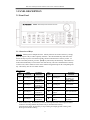
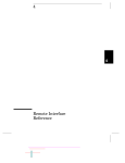
3. PANEL DESCRIPTION
3.1 Front Panel
3.1.1 Overview of Keys:
Summary: Most keys have multiple functions. Primary functions are written on the key. Simply
press the respective key to enable a primary functions. All Function/Mode keys and some of the
numerical entry keys have associated secondary functions indicated above each key in blue. To
activate a secondary function, press the 【shift】key followed by the desired key. The bottom row
of the Function/Mode keys can be used to enter units directly. The unit is indicated below each key.
To enter a unit, enter a numerical value via the numerical keypad then press the corresponding unit
key. The unit key also serves as Enter function.
Data entry keys:
Key
Name
*:
Main
Function
0
Input Digit 0
1
Input Digit 1
2
Input Digit 2
3
Input Digit 3
4
Input Digit 4
5
Input Digit 5
6
Input Digit 6
Secondary
Function
Key
Name
Enter SW mode
7
Input Digit 7
8
Input Digit 8
9
Input Digit 9
Not available
●
Input decimal point
Reset Unit
Enable ARB1
waveform ***
Enable ARB2
waveform ***
Enable ARB3
wave ***
Enable ARB4
waveform***
Enable ARB5
waveform ***
Enable ARB6
waveform***
▬
◄
►
Main function
Input negative
symbol
Move arrow key to
left *
Move arrow key to
right **
Secondary
Function
Enable ARB7
waveform ***.
Enable ARB8
waveform ***
Enter system menu
Select pulse
Select Arblist
waveform
Direct number entry: Press this key to clear the least significant bit of the displayed number.
Useful for correcting number entry before entry is confirmed with unit key.
External totalize mode: Press this key to stop counting and display present counting value.
Press again to resume counting.
11
4080 series Arbitrary/Function Generator with Counter –Instruction Manual
**:
External totalize mode: Press this key to reset and resume event counter
*** models 4084AWG and 4086AWG only
Function/Mode Keys:
Key name
Freq./Period
Toggle between
Frequency &
Period.
Ampl./Pulse
width
Amplitude Select.
FSK/PSK
FSK/PSK
Function Select
Menu
Menu Selection
FM
Enable FM mode
AM
Enable AM mode
Enable Sweep
mode
Enable Burst
mode
Sweep
Burst
Secondary
Function
Main Function
Enable Sine Wave
Secondary
Function for
Counter Mode
Unit Entry
Not Available
Not Available
Not Available
Not Available
Not Available
Not Available
Not Available
Not Available
Enable Square
Wave.
Enable Triangle
Wave
Enable positive
ramp
Enter Storage
menu
Enter Recall menu
Enter Counter
Mode
Attenuation
Selection
Low Pass Select
Freq. Meas./
Totalize Enable
MHz, Vrms
DC Offset Select
Gate Select
Hz, dBm
ms, mVpp
kHz, mVrms
Other Keys:
Key Name
Main Function
Output
Main OUTPUT signal On/Off
Shift
Select secondary function
Other Function
Generate single trigger in sweep and
burst mode
Enter units in s, Vpp, N
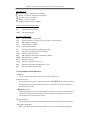
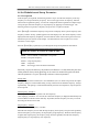
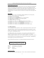
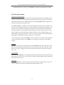
3.1.2 Display Annunciators:
Display areas:
① Waveform Indication
② Main Alphanumeric Display
③ Frequency Measurement/Totalize Settings
④ Instrument states
12
4080 series Arbitrary/Function Generator with Counter –Instruction Manual
Waveform states
Sine waveform is enabled (,main waveform)
Square waveform is enabled (main waveform)
Triangle waveform is enabled
Ramp waveform is enabled
Arb Arbitrary waveform mode is enabled
Frequency Measurement/Totalize states
Filter:
Low Pass Filter is enabled
ATT:
Input Attenuator is enabled
GATE: Gate received trigger
Function Generator states
Adrs:
The instrument is in remote state.
Trig:
Function Generator is waiting for a single trigger or external trigger.
FM:
FM modulation is enabled
AM:
AM modulation is enabled
Sweep: Sweep mode is enabled
Ext:
Generator is configured for external signal input
Freq:
Frequency measurement function is enabled
Count: Totalize function is enabled
FSK:
FSK (frequency shift keying) modulation is enabled
◄FSK: PSK modulation is enabled
Burst:
Burst mode enabled.
Offset: DC offset of output signal is not 0.
Shift:
Shift key has been pressed, Shift mode is active
Rmt:
The instrument is in remote state.
3.13 Description of front panel keys
【shift】key
Access secondary functions or to enter units “seconds”, Vpp and “N”
Numerical key pad:
Keys are used for direct entry of numerical values. Keys【0】
【●】
【-】are assigned secondary
functions to enter the systems menu, reset the unit to its default values or revert to Standard
Waveform (“SW”) mode.
【◄】【►】arrow keys
The primary function is to move the flashing digit left or right or to select the desired arbitrary
waveform from the Arb List (secondary function). When in Counter Mode, these 2 keys are
used to start/stop or reset/resume the counter.
【Freq/Period】key:
Toggle between frequency and period display (primary function) or to enable sine waveform.
【Ampl/Pulse Width】key:
Display and adjust the amplitude of waveforms or, when in pulse mode, toggle the display
13
4080 series Arbitrary/Function Generator with Counter –Instruction Manual
between amplitude and pulse width. The secondary function activates the square waveform
【FSK/PSK】key:
Toggle between FSK and PSK modulation (primary function). Activate triangle waveform
【Menu】key:
Enter modulation parameters for FSK, PSK, FM, AM and burst modulation and for sweep
mode. When in standard waveform mode (no modulation, main waveforms enabled), this key
can also be used to toggle the units for the amplitude display value between Vpp, Vrms and
dBm. (Press the Amplitude key first, then the Menu key to toggle between the units). The
secondary function enables the ramp waveform.
【FM】key:
Activate FM modulation (primary function). Enter Storage mode (secondary function). Enter
units ms or mVpp after entering the desired value by numerical key pad. In Counter Mode, this
key turns the input attenuator on or off.
【AM】key:
Activate AM modulation (primary function). The secondary function is used to recall and
recreate signals stored in status memory. Enter units “MHz and “Vrms” after entering the
desired value by numerical key pad. Enable the low pass filter when in Counter mode.
【Sweep】 key:
Activate sweep mode. Select frequency measuring and totalize mode (secondary function) .
Enter units kHz or mVrms after entering the desired numerical value directly via the keypad.
Use the Shift key to toggle between frequency measurements and totalize mode.
【Burst】key:
Activate burst mode (primary function). Enter DC offset mode (secondary function). Enter
units Hz or dBm. When in frequency measurement mode, press this key to enter the gate time.
【Output】key
Press this key to toggle the main OUTPUT signal between the ON and OFF state. By default
the output is turned on, indicated by the green LED and the currently active wave form is
available at the OUTPUT terminal. In Burst or Sweep mode, this key is also used to generate a
single trigger.
3.14 Description of menu parameters
Use this key to configure modulation parameters, sweep mode parameters and system parameters.
Modulation and Sweep mode: After enabling modulation or sweep mode, press “menu” to
configure the related parameters. Each time you press the menu key, the parameter will flash for 1
second, followed by the currently active value of that parameter. Use the knob or numerical keys to
enter a new value. Once the parameter is set, press 【menu】 to advance to the next parameter.
Continue pressing the menu key to cycle through all parameters. Press 【Shift】【SW】to return to
the main waveform mode and to set the carrier waveform parameters.
Sweep Mode:
MODE —> START F —> STOP F —> TIME —>TRIG
14
4080 series Arbitrary/Function Generator with Counter –Instruction Manual
MODE: Select LINEAR or LOGarithmic sweep
START F :Sweep start frequency
STOP F: Sweep stop frequency
TIME: Sweep time
TRIG: Select trigger source, INTernal or EXTernal
FM modulation:
FM DEVIA—> FM FREQ —> FM WAVE —> FM SOURCE
FM DEVIA: Peak frequency deviation
FM FREQ: Modulating signal frequency
FM WAVE: Modulating signal waveform (sine, square, triangle rising or falling ramp)
FM SOURCE: Toggle between internal and external modulating signal.
AM modulation:
AM LEVEL —> AM FREQ —> AM WAVE —> AM SOURCE
AM LEVEL: Modulation depth
AM FREQ: Frequency of modulating signal
AM WAVE: Modulating signal waveform (sine, square, triangle rising or falling ramp)
AM SOURCE Select internal or external modulating signal
Burst modulation:
TRIG —> COUNT —> SPACE T —> PHASE
TRIG
Select trigger source, internal or external
COUNT: Number of burst cycles
SPACE T:Burst time spacing
PHASE: starting phase of the burst
FSK modulation:
START F —> STOP F—> SPACE T —> TRIG
START F
STOP F
SPACE T
TRIG
Primary frequency (same as carrier wave)
the second frequency (hop frequency)
FSK rate
Select trigger source, external or internal
PSK modulation
P1 —> P2 —> SPACE T —> TRIG
P1
P2:
phase value #1
phase value #2
15
4080 series Arbitrary/Function Generator with Counter –Instruction Manual
SPACE T:
TRIG:
PSK rate
trigger mode, internal or external
System Function Mode:
POWER ON —> ADDRESS —> OUT Z —> INTERFACE—>…..
…………BAUD —> PARITY
POWER ON “Power on” state
ADDRESS: set GPIB address (option)
OUT Z:
Configure amplitude display value for 50Ω or high impedance load termination
INTERFACE: Select RS232 or GP-IB (IEEE-488) interface (option)
BAUD:
Baud rate for the RS232 interface
PARITY:
Parity and Data Bits configuration for RS232
16
4080 series Arbitrary/Function Generator with Counter –Instruction Manual
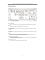
3.2 REAR PANEL
Ext. Trig/FSK/Burst:
Input Terminal for external trigger signals for FSK/PSK Burst modulation and sweep mode
MOD In
Apply modulating signal for AM and FM to this Input terminal
Meas Freq/TOT In
Input terminal for Universal Counter which operates in frequency measurement or Totalize
mode
MOD OUT
The internally generated modulating signal when in AM mode will be available at this output
RS232C
RS232 interface for remote control of instrument (all models) or for download of custom
arbitrary waveforms (models 4084AWG and 4086AWG only)
AC Socket and fuse compartment
Connect the supplied power line cord to this receptacle. Make sure to install the appropriate
fuse according to the selected AC voltage.
AC Input Selector switch
Set this switch to the corresponding AC voltage in your area
17
4080 series Arbitrary/Function Generator with Counter –Instruction Manual
4. OPERATING INSTRUCTIONS
4.1 Installation
This section contains installation information, power requirements and initial inspection and signal
connections for the 4080 series generators.
Mechanical Inspection
This instrument was carefully inspected before shipment. Upon receipt, inspect the instrument for
damage that might have occurred in transit. If any sign of damage is found, notify your B+K
Precision distributor.
Instrument Mounting
The 4080 Series is intended for bench use. The instrument includes a handle adjustable for
optimum panel viewing angle. The instrument does not require special cooling when operated
within conventional temperature limits.
Power Requirements
The 4080 Series can be operated from any source of 99V to 242V AC and frequency of 48Hz to
63Hz. The maximum power consumption is 35 VA. Replace fuses with the same type, according to
the rating indicated on the rear panel of the instrument.
The instrument power fuse is located in a fuse compartment below the AC input receptacle. To
access the fuse, first disconnect the power cord and then remove the fuse cartridge.
Power-on procedure
Turn on the instrument by pressing the power key on the front panel of the unit. The display should
be flashing “BK PRECISION” for 2 seconds followed by the model number. e.g. .“4084AWG” for 1
second. By default, the instrument will enter the standard waveform (“SW”) mode with the
frequency set to 10.00000000 kHz and the waveform annunciator displaying the “~ “ symbol. If
the Power ON configuration in the systems menu was modified, the parameters of the last operation
before power-down will be displayed.
4.2. Main operating modes
“SW” standard waveform mode
In this mode, the generator outputs any of the 27 build-in waveforms, including the 2 “main
waveforms” sine and square. This also includes the 8 user programmable arbitrary waveforms
(models 4084AWG and 4086AWG only). For most waveforms, you can set frequency, amplitude
and DC offset. In this mode, modulation and sweep is not active and all annunciators in status area 4
are turned off. When modulation or sweep is enabled, press【shift】
【SW】to return to this mode.
Modulation, Pulse and Sweep Mode
In this mode, the generator operates like a conventional function generator and the Arb annunciator
is turned off. The user can select one of the modulation modes AM, FM, FSK, PSK, Burst or sweep
mode. The 2 main waveforms sine and square can be used as carrier signal.
There is a close, reciprocal relationship between the modulation/sweep mode and the standard
18
4080 series Arbitrary/Function Generator with Counter –Instruction Manual
waveform mode used to set the sine or square wave parameters. When one of the modulation modes
is active, the parameters of the carrier wave are carried over from the Standard Waveform Settings
(for sine or square). Press【shift】
【SW】to toggle between any of the modulation/sweep modes (to
set the modulation parameters) and the standard waveform mode (to define the carrier settings for
frequency, amplitude and DC offset). On the other hand, the carrier frequency can also be set in the
modulation/sweep menus and if changed, will overwrite the standard waveform frequency setting.
Example: When transitioning from standard waveform mode to FM modulation mode, (by pressing
the FM button) the parameters set previously in “SW” mode carry over to the FM mode and are now
defining the FM carrier. If the FM carrier frequency in the FM modulation menu is changed, it will
also “overwrite” the frequency setting of the standard waveform” settings.
To adjust the duty cycle, enable pulse mode by pressing 【shift】 【◄】. Note that the duty cycle
can only be adjusted in pulse mode.
4.3 Waveform Selection:
Enabling common waveforms
Press【shift】 followed by the waveform key to select one of the 5 common waveforms sine, square,
triangle, ramp and pulse. The corresponding waveform annunciator will be displayed in the
waveform display area. Note that the instrument operates in Function Generator mode when
selecting sine and square and in ARB mode for the remaining functions. (Arb annunciator is lit).
Note: The 5 common waveforms can also be output by selecting the corresponding number from the
ArbList in this section.
Example: Press 【Shift】【FSK/PSK】to enable the triangle waveform
Enabling stored waveforms from the Arb List
Make sure you are in “SW” mode. (All area 4 status annunciators are off). If modulation or sweep
is active, press【shift】 【SW】to return to the standard waveform mode.
Press【shift】
【►】to enter the ArbList: Waveform,”6: NOISE” is enabled and appears on the display.
Use the knob or the numeric keypad to select one of the 27 stored waveforms from the ArbList
according to the table in this section.
Example: To select negative ramp DOWN_RAMP, do the following:
Press 【shift】 【►】(enter ArbList)
Press 【5】【N】(enable DOWN_RAMP)
or
select waveform with the knob
Models 4084AWG and 4086AWG only: Locations 28-35 are reserved for the storage of user
defined arbitrary waveforms. The display name for these waveforms is ARB1-ARB8. These
memory locations can be accessed in one of 2 ways:
a) Enter the ArbList, then use the knob or the numeric keypad to enable waveforms ARB1 – ARB8
b) Press 【Shift】followed by any number between 1-8.
Example: Press 【Shift】【2】to enable waveform stored in memory location ARB2
19
4080 series Arbitrary/Function Generator with Counter –Instruction Manual
Table of stored waveforms (ArbList) and their memory locations
No.
1
2
3
4
5
6
7
8
9
10
11
12
13
14
Waveform
Sine wave
Square wave
Triangle wave
Ramp
Falling ramp
Noise
Pulse wave
Positive pulse
Negative pulse
Positive DC
Negative DC
Stair wave
Coded pulse
Full wave
rectified
Display Name
SINE
SQUARE
TRIANG
UP_RAMP
DOWN_RAMP
NOISE
PULSE
P_PULSE
N_PULSE
P_DC
N_DC
STAIR
C_PULSE
No.
15
16
17
18
19
20
21
22
23
24
25
26
27
COMMUT_FU
28~35*
Waveform
Half-wave rectified
Sine transverse cut
Sine vertical cut
Sine phase modulation
Logarithmic function
Exponential function
Half-round function
SINX/X function
Square root function
Tangent function
Cardiac wave
Earthquake wave
Combination wave
User programmable
Arbitrary waveforms
Display Name
COMMUT_HA
SINE_TRA
SINE_VER
SINE_PM
LOG
EXP
ROUND_HAL
SINX/X
SQU_ROOT
TANGENT
CARDIO
QUAKE
COMBIN
ARB1~ARB8
Note:
*No 28~35: memory location for user programmable waveforms, models 4084AWG and 4086AWG only. Refer to
chapter 7 for more details
4.4 Data entry
Using the arrow keys and the knob
Use the knob and arrow keys to modify the displayed number.
Use the【◄】
【►】keys to move the flashing digits left or right then adjust the value with the knob.
Using this method of entry, the output signal will be updated immediately. Move the arrow keys left
for coarse adjustment and right for fine adjustment.
To disable the knob, use the【◄】
【►】 key to move the cursor all the way to the left or right until
the digits stop flashing. Now data entry via the knob is disabled.
Direct entry using the numerical key pad
Use the numerical keypad to enter a number with the appropriate unit.
Enter numbers from left to right. Use the 【●】key to enter a decimal point. Enter 【-】for negative
numbers. Repeatedly pressing this key will toggle between positive (no sign visible) and negative
numbers. Numerical entries do not update the output signal until a unit key has been pressed. Once
you entered the correct numerical value, press the appropriate unit key to assign a unit and to make
the entry effective. The instrument will now output a signal according to the displayed data.
For entries not associated with a unit, press the shift key (“N” = “no unit”) to make the entry
effective.
Note: Numerical values entered via the keypad are not effective until a valid unit key or shift (“N”)
has been pressed.
20
4080 series Arbitrary/Function Generator with Counter –Instruction Manual
Entry of invalid key presses or invalid values
If the entered value exceeds the rated range, a beep sound will be heard. If the entered value is below
the lower limit, the instrument will automatically change the entry to the lowest possible value. If
the entered value exceeds the upper limit, the instrument will automatically revert to the maximum
value.
Example: When trying to entering 90MHz in a model 4086 (80 MHz max), a beep will be heard and
the value will be forced to 80 MHz.
Invalid keys: A beep sound will inform the user that the key entry is invalid. The instrument will
simply ignore the key pressed.
Example: Key【-】is pressed when trying to enter a frequency value. The instrument will ignore the
entry and respond with a “beep” sound.
4.5 Output Configuration
4.5.1 Set Frequency and Period
The【frequency/period】key is used to toggle between Frequency and Period display of the standard
waveform or the carrier waveform.
Frequency
Press the 【frequency】 key to display the current frequency value. The value can be modified using
the numerical keypad or the knob.
Example: To set a frequency value of 5.8 kHz, enter the following key sequence:
【frequency】
【5】【●】
【8】【kHz】
or
【frequency】
【5】【8】
【0】【0】【Hz】
or
use the knob and 【◄】
【►】 keys
The display will be 5.80000000 kHz.
Period Setting:
The signal frequency can also be displayed or entered as a period value. If the current display is
frequency, press the【frequency/period】key to display the current period value. Values can be
entered with the numerical key pad or using the knob.
Example: To set a period value of 10ms, enter the following sequence of keys:
【Period】【1】
【0】【ms】
Or
use the knob and【◄】【►】 keys
4.5.2 Set Amplitude
Press the【Amplitude】key to display the current amplitude value. Modify the value using the knob
or the numerical keypad.
Example: Set amplitude to 4.6V peak-to-peak:
Press【Amplitude】【4】【●】【6】【Vpp】
or
modify values using the knob and arrow keys
21
4080 series Arbitrary/Function Generator with Counter –Instruction Manual
In case of standard waveforms “sine”, “square”, “triangle”, “rising ramp” and “pulse”, numbers can
be entered and displayed as Peak-to-peak value (Vpp or mVpp) , root mean square value (Vrms and
mVrms) or dBm value.
All other waveforms can only be edited or displayed using Vpp or mVpp units only.
4.5.3 Set DC Offset Voltage
Press【shift】
【offset】to display the current DC offset value. If the current DC offset value is not
equal to zero, the annunciator “Offset” will turn on. The DC offset value can be entered directly or
using the knob.
Example: Set an offset value -1.6V peak-to-peak
Press【shift】
【offset】【-】
【1】【●】
【6】【Vpp】
or
【shift】【offset】【1】【●】
【6】【-】【Vpp】
or
use the knob for value entry
Zero Point Adjustment:
For zero point adjustment of the output signal, using the knob is more convenient than direct entry
via the numerical keypad. The transition of the DC offset Voltage from plus to minus sign will be
automatic when passing through the zero point. The input range of the signal amplitude and DC
offset should satisfy the following equation: |Voffset| + Vpp/2 ≤ Vmax, with the parameters
defined as followed:
Vpp is the peak-to-peak value of the amplitude
|Voffset| is the absolute value of the DC offset
Vmax is 10V at high impedance and 5V at 50Ω load.
The following table shows the corresponding relationship between the Vp-p value of the amplitude
and the absolute DC offset value at high impedance:
Vp-p value of AC signal
1.001 V ~ 20.00 V
316.1 mV ~ 1.000 V
100.1 mV ~ 316.0 mV
31.01 mV ~ 100.0 mV
2.000 mV ~ 31.00 mV
Absolute value of DC offset
0 ~ (10.000-Vpp/2) V
0 ~ 2.000 V
0 ~ 632.9 mV
0 ~ 200.9 mV
0 ~ 62.99 mV
4.5.4 Adjustment of duty cycle
If the current waveform is pulse, and the current display value is amplitude, use the 【Ampl/Duty】
button to toggle between Amplitude and Duty cycle display. When the pulse width is displayed,
enter a value via the numeric keypad or the knob. The valid range is 0.1% ~ 99.9% for frequencies
below 10kHz with a maximum resolution of 0.1%. For frequencies between 10kHz~100kHz the
range is 1% ~ 99% and the maximum resolution is 1%.
Example: Enter a duty cycle value of 60.5%
Press 【Pulse】【6】【0】
【●】
【5】【N】
or
use the knob and arrow keys
22
4080 series Arbitrary/Function Generator with Counter –Instruction Manual
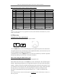
4.5.5 Sync/TTL Signal
A TTL signal output is provided on the front-panel SYNC terminal. All signals, including
modulated signals and arbitrary waveforms (except DC and noise) have an associated TTL signal.
This signal is a TTL “high” when the waveform’s output (on the main terminal) is positive, relative
to zero volts. The signal is a TTL “low” when the output is negative. The TTL signal is generated by
passing the main output signal through a comparator configured as a Schmitt Trigger. The TTL
signal will transition to high or low once the main output signal exceeds a certain threshold value,
which causes a time delay between the main output signal and the TTL signal.
4.5.6 Signal Store and Recall
Up to 10 different instrument states can be stored in non-volatile memory. This enables you to recall
the entire instrument configuration with a single command from the remote interface or with just a
few key presses from the front panel.
The state storage feature “remembers” the function (including arbitrary waveforms), frequency,
amplitude, DC offset, duty cycle, as well as any modulation parameters. To recall a stored state, you
must use the same memory location used previously to store the state.
The last state of the instrument before power-off is automatically stored in location #0, therefore a
total of 11 groups locations ranging from 0 ~ 10 can be recalled.
Example:
Store the current output signal in group location #1:
【Shift】【Store】
【1】【N】
The following prompt will be displayed for a few seconds: “STORE
Previously stored signal configurations will be overwritten.
1”
To recall group location #1 and make it the active output signal:
Press【Shift】
【recall】【1】
【N】
The following prompt will be displayed for a few seconds: “RECALL: 1”
The stored signals can be continuously recalled and reproduced by scrolling through each location
using the knob.
23
4080 series Arbitrary/Function Generator with Counter –Instruction Manual
4.6 Set Modulation and Sweep Parameters
4.6.1. Sweep mode
In the frequency sweep mode, the function generator “steps” from the start frequency to the stop
frequency at a sweep rate which you specify. You can sweep up or down in frequency, and with
either linear or logarithmic spacing. You can also configure the function generator to output a single
sweep (one pass from start frequency to stop frequency) by applying an external trigger. The
function generator can produce a frequency sweep for sine or square waveforms.
Press 【Sweep】 to enable the frequency sweep mode. The display shows a preset frequency (start
frequency) and the “Sweep” symbol appears in the state display area. The carrier frequency will be
displayed and the frequency, amplitude, waveform and DC offset of the carrier signal can be set as
described in previous sections of this chapter. The main functions sine or square wave can be
selected as a carrier signal.
Press the 【menu】key repeatedly to cycle through the sweep menu parameters listed below.
MODE —> START F —> STOP F —> TIME —>TRIG
MODE Select LINEAR or LOGarithmic sweep mode
START F sweep start frequency
STOP F: sweep stop frequency
TIME: sweep time
TRIG: Select trigger source INTernal or EXTernal
Each time you press the menu key, the parameter will flash for 1 second, followed by the value
of that parameter. Sweep mode parameters can be entered via numerical keypad or the knob.
Once the parameter is set, press 【menu】 to advance to the next parameter.
Sweep mode
MODE parameter: Select LINear (No.1) or LOGarthimic (No.2). In linear sweep mode, the output
frequency changes in a linear fashion during a sweep, whereas in LOG mode the frequency changes
exponentially. The spacing is calculated automatically based on start frequencies, stop frequencies
and sweep time.
Start frequency “START F”:
The frequency where the sweep starts is the start frequency.
After displaying “START F” for 1 second, the current start frequency is displayed automatically and
can be modified via knob or direct data entry. By default, the start frequency will carry over from
the setting for the main wave form
.
Stop frequency “STOP F”
The sweep stops at the frequency “STOP F”
When the start frequency is lower than the stop frequency, the frequency sweep increases gradually
from start frequency (low frequency) to stop frequency (high frequency); When the start frequency
is higher than stop frequency, the frequency sweep decreases gradually from the start frequency
(high frequency) to stop frequency (low frequency).
24
4080 series Arbitrary/Function Generator with Counter –Instruction Manual
The frequency range from start frequency to stop frequency is 1µHz ~ Fmax in linear sweep mode
and 1mHz ~ Fmax in log sweep mode. (Fmax see specification section for main waveform)
Sweep time “TIME”
The time needed to complete one sweep from start to stop frequency is called sweep time.
The sweep time range is 1ms ~ 800s in linear sweep mode or 100ms ~ 800s in LOG sweep mode.
Trigger mode “TRIG”:
A sweep can be triggered internally or externally. The corresponding display values are “1: INT”
and “2: EXT”. The default value is INTernal trigger. In internal trigger mode, the instrument will
continuously sweeps from the start frequency to the stop frequency according to the Sweep
parameters. An external trigger signal can be generated in one of two ways.
a) Press the【output】key to trigger a single sweep. The signal frequency will in/decrease from start
frequency to stop frequency, then sweep will stop.
b) Apply an input trigger signal to the “EXT Trig” terminal on the rear panel. A rising edge will
trigger a single sweep. In external trigger mode, symbols “Trig” and “Ext” are displayed in the
status field.
Start and stop of sweep
The sweep will start automatically once sweep mode is selected. If you don’t want to output the
sweep signal, simply press the 【output】key to disable the signal output (LED above Output button
is OFF). Once all the parameters are set, you can make the sweep signal available at the output by
pressing the Output button again. In external trigger mode, the 【Output】key functions only as a
single pulse trigger key, the Output On/Off functionality is now disabled and the output LED will
always be lit.
Sweep configuration example
Sweep parameters are as followed: Frequency range 100Hz~200kHz, sweep time 10s, linear sweep,
internal trigger mode.
Set the carrier frequency parameters
Press【sweep】
Press【menu】
Select “MODE”, wait, then enter【1】【N】(linear sweep)
Press【menu】to select “START F”, press【1】
【0】【0】【Hz】
Press【menu】to select “STOP F”, press【2】【0】【0】
【kHz】
Press【menu】to select “TIME, press【1】【0】
【s】
Press【menu】 to select “TRIG”, press【1】【N】
Hint: The frequency displayed immediately after pressing [Sweep] is the start frequency. Any
changes to that value will automatically update parameter “START F”
25
4080 series Arbitrary/Function Generator with Counter –Instruction Manual
4.6.2 FM modulation
A modulated waveform consists of a carrier waveform and a modulating waveform. In FM, the
frequency of the carrier is varied by the amplitude of the modulating waveform. The function
generator will accept an internal or external FM modulating signal.
Press the 【FM】key to enter into FM mode. The display will indicate the carrier frequency and the
“FM” annunciator will be lit. The frequency, amplitude, waveform and DC offset of the carrier
signal can be set as described in the previous section. Only the main functions sine or square wave
can be selected as a carrier signal.
Press the 【menu】 key repeatedly to cycle through the FM modulation parameters listed below.
FM DEVIA —> FM FREQ —> FM WAVE —> FM SOURCE
FM DEVIA
FM FREQ:
FM WAVE:
FM SOURCE
Peak frequency deviation
Frequency of modulating signal
Waveform of modulating signal
Toggle between internal or external modulating signal
Each time you press the menu key, the parameter will flash for 1 second, followed by the value of
that parameter. FM modulation parameters can be entered directly or via the knob. Once the
parameter is set, press 【menu】 to advance to the next parameter.
Peak frequency deviation ”FM DEVIA”
Explanation: The variation in frequency of the modulating waveform from the carrier frequency
(center frequency).
Range of deviation: For internal FM modulation, the maximum value should not exceed 50% of the
carrier frequency. In external FM mode, the maximum deviation is 10% of the carrier frequency.
Additionally, the frequency deviation plus carrier frequency should not exceed the maximum
operating frequency of the instrument. (Fc + Fd <= Fmax + 100 kHz) For Fmax refer to the
specifications for main waveforms.
This parameter applies only when “FM SOURCE” is set to “INTernal”.
Modulating signal frequency “FM FREQ”:
The frequency range of the modulating signal is 100µHz ~ 10kHz.
This parameter applies only when “FM SOURCE” is set to “INTernal”.
Modulating signal waveform “FM WAVE”
Waveform of the modulating signal: Waveforms sine, square, triangle, rising and falling ramp can
be used as the modulating signal. Waveforms are selected by entering the corresponding number,
numbers 1 – 5.
This parameter applies only when “FM SOURCE” is set to “INTernal”.
Modulating signal source “FM SOURCE”:
The modulating signal could be an internal signal and external input signal. The corresponding
prompts are “1: INT” and “2: EXT”, the default is INTernal signal. The external modulating signal
is applied to terminal “Mod In” on the rear panel (max signal amplitude is 3Vp-p). When
26
4080 series Arbitrary/Function Generator with Counter –Instruction Manual
modulating signal source “external” is selected, the symbol “Ext” is displayed and parameters FM
DEVIA, FM FREQ and FM WAVE do not apply (disabled)
Start and stop of FM modulation
An FM signal is generated once FM function mode is selected. The instrument will automatically
output a signal according to the preset parameters. If you do not want to output the FM signal,
simply press the【output】key to disable the signal output (LED above Output button is OFF). Once
all the parameters are set, you can turn make the FM signal available at the output by pressing the
Output button again.
FM example:
Example configuration: Carrier signal is square, frequency is 1MHz, amplitude is 2V, modulating
signal is generated internally. Carrier waveform is sine (No. 1), Frequency is 5kHz. Peak frequency
deviation is 200kHz.
Press【FM】
Press【frequency】then【1】【MHz】 (set carrier frequency)
Press【amplitude】, then【2】【V】 (set carrier amplitude)
Press【Shift】and 【square】 (set carrier waveform)
Press【menu】, select “FM DEVIA”, enter【2】【0】
【0】【kHz】 (set FM deviation)
Press【menu】, select “FM FREQ”, press【5】
【kHz】 (set FM frequency)
Press【menu】, select “FM WAVE, press【1】【N】 (set FM waveform as sine)
Press【menu】, select “FM SOURCE”, press【1】【N】 (set FM source as internal)
4.6.3 AM modulation
AM stands for amplitude modulation.
Press【AM】to enable AM modulation. The carrier frequency and the AM annunciator is displayed.
Frequency, amplitude, waveform and DC offset of the carrier signal can be set as described in the
previous section of this chapter. The parameters carry over from the parameter settings of the main
waveforms sine and square. In AM only sine and square waves can be selected for carrier.
Press the 【menu】 key repeatedly to cycle through the AM modulation parameters listed below.
AM LEVEL—> AM FREQ —> AM WAVE—>AM SOURCE
AM LEVEL:
AM FREQ:
AM WAVE:
AM SOURCE:
Modulation depth
Frequency of modulating signal
Waveform of modulating signal
internal or external modulating signal
In AM mode, to ensure normal signal output at 100% modulation depth, the instrument reduces the
peak-to-peak value of the carrier by 50%. Only sine and square waves can be selected as AM
carrier.
27
4080 series Arbitrary/Function Generator with Counter –Instruction Manual
Modulation depth “AM LEVEL”:
The range of modulation depth is 1% ~ 120%.
Modulating frequency “AM FREQ”
Frequency of the modulating signal. Range is 100µHz ~ 20kHz. Parameter does not apply when
“AM SOURCE” is set to “EXTernal”
Modulating signal waveform “AM WAVE”:
Waveforms sine, square, triangle, rising and falling ramp can be used as the modulating signal.
Waveforms are selected by entering the corresponding number, numbers 1 – 5. Parameter does not
apply when “AM SOURCE” is set to “EXTernal”
Modulating signal source “AM SOURCE”
Select internal signal and external input signal. The number and prompt symbols are 1: INT, 2: EXT.
The default of the instrument is internal signal. The external modulating signal is input through the
rear panel “Modulation Input” terminal (with a maximum signal amplitude of 3Vp-p).
Enabling and disabling the AM signal:
An AM signal is generated once AM modulation is selected. The instrument will automatically
output a signal according to the preset parameters. If you do not want to output the AM signal,
simply press the【output】key to disable the signal output (LED above Output button is OFF). Once
all the parameters are set, you can make the AM signal available at the output by pressing the Output
button again.
AM example:
Configuration: carrier signal is square wave, frequency 1MHz, amplitude 2V, internal signal,
modulating waveform sine wave (No.1), modulating signal frequency 5kHz, modulation depth
50%:
Press【AM】 (activate AM modulation)
Press【frequency】, then【1】【MHz】 (set carrier frequency)
Press【amplitude】, then【2】【V】 (set carrier amplitude)
Press【shift】 then【square】 (set carrier waveform)
Press【menu】, select “AM LEVEL”, press【5】
【0】
【N】 (set modulation depth)
Press【menu】, select “AM FREQ”, press【5】【kHz】 (set modulating signal frequency)
Press【menu】, select “AM WAVE”, press【1】【N】 (set AM wave as sine)
Press【menu】 select “AM SOURCE”, press【1】【N】 (set AM source to internal)
4.6.4 Burst modulation
You can configure the function generator to output a waveform with a specified number of cycles,
called a burst. You can output the burst at a rate determined by the internal rate generator or an
external signal applied to the rear-panel connector. The function generator can produce a burst using
sine or square waveforms.
Press【Burst】to enter into burst mode. The carrier frequency and the Burst annunciator are
displayed. Frequency, amplitude, waveform and DC offset of the carrier signal can be set as
28
4080 series Arbitrary/Function Generator with Counter –Instruction Manual
described in the previous section of this chapter. The parameters carry over from the parameter
settings of the main waveforms sine and square. Press the 【menu】 key repeatedly to cycle through
the burst menu parameters listed below.
TRIG —> COUNT —> SPACE T —> PHASE
TRIG:
COUNT:
SPACE T:
PHASE:
Trigger source
Number of cycles
Burst time spacing
The starting phase of the burst
Select trigger source “TRIG”
Three trigger sources are available. Internal trigger and 2 types of external triggers sources, external
gated and single. The corresponding menu parameters are 1: INT, 2: EXT and 3: SINGLE. The
default is internal triggering.
a) Internal trigger
When the internal trigger source is selected, the frequency at which the burst is generated depends
on parameter SPACE_T, burst count and the burst carrier frequency.
b) Single trigger mode
Generate a single trigger event by pushing the 【output】key once or by applying a single TTL pulse
at the “Ext.Trig” input terminal in the rear panel. A single burst with predefined parameters will be
generated.
c) External gated burst mode
The TTL signal applied to “Ext. Trig” input terminal in the rear panel will enable or disable the
output of the generator. When the TTL level of the gate signal is high, the generated will generate
burst pulses according to the parameters of the set carrier frequency. Burst parameters COUNT and
SPACE_T are ignored in this mode. Anunciators “Trig” and “Ext” turn on when this mode is active.
Burst count “COUNT”:
Definition: The number of cycles to be output per burst.
Range: 1 ~10000 cycles in 1 cycle increments. Additionally, the minimum number of cycles must
also satisfy FC/50khz +1。Parameter does not apply when “TRIG” is set to “EXTernal”.
Burst spacing time “SPACE T”:
Definition: Time interval between the 2 consecutive groups of bursts (time interval during which
there is no burst signal present) Parameter does not apply when “TRIG” is set to “EXTernal” or
“SINGle”.
Range: 0.1ms ~ 800s.
Starting phase of the burst “PHASE”
Burst phase: 0.0º ~ 360.0º in 0.1º increments
29
4080 series Arbitrary/Function Generator with Counter –Instruction Manual
Enabling/disabling the burst signal
The generator outputs a burst as soon as the burst key is pressed. The instrument will automatically
output a signal according to the preset parameters. If you do not want to output the burst signal,
simply press the【output】key to disable the signal output (LED above Output button is OFF). Once
all the parameters are set, you can make the burst signal available at the output by pressing the
Output button again. Note that the output on/off function does not apply when single trigger mode
is selected.
Burst example:
Configuration: Burst is sine wave with frequency 20kHz, amplitude 2V, 10 cycles per group,
spacing time between each group 10 ms, start phase 90.0º
Press【burst】 (enter into burst mode)
Press【frequency】, press【2】【0】
【kHz】 (set wave form frequency)
Press【amplitude】, press【2】【V】 (set waveform amplitude)
Press【shift】and【sine】 (set waveform)
Press【menu】, select “TRIG”, press【1】【N】 (set trigger mode as internal)
Press【menu】, select “COUNT”, press【1】
【0】【N】 (set number of bursts/cycles)
Press【menu】, select “SPACE T”, press【1】【0】【ms】 (set space time)
Press【menu】, select “PHASE”, press【9】【0】【N】 (set the start phase of burst)
4.6.5 FSK modulation
You can configure the function generator to “shift” its output frequency between two preset values
using FSK modulation. The rate at which the output shifts between the two frequencies (“carrier
frequency” and “hop frequency”) is determined by the internal rate generator or the signal level on
the rear-panel ext Trig/FSK/Burst terminal.
Press【FSK/PSK 】to enable FSK modulation. A preset frequency and the FSK annunciator is
displayed. The preset frequency is identical to the “START F” parameter. Any changes
automatically update “START-F” and vice versa. Frequency, amplitude, waveform and DC offset of
the carrier signal can be set as described in the previous section of this chapter. In FSK/PSK only
sine and square waves can be selected as carrier wave.
Press the 【menu】 key repeatedly to cycle through the FSK menu parameters listed below.
START F —> STOP F—> SPACE T —> TRIG
START F:
STOP F:
SPACE T:
TRIG:
First frequency or carrier frequency
Second frequency (hop frequency)
FSK rate
Trigger source
Trigger source “TRIG”
Select internal signal and external input signal, 1: INT or 2: EXT. The default of the instrument is
30
4080 series Arbitrary/Function Generator with Counter –Instruction Manual
“internal”.
In internal mode, the rate at which the signal shifts between the carrier and hop frequency is
determined by the FSK rate.
In external trigger mode, the trigger signal applied to the trigger input terminal on the rear panel
determines the FSK rate. Logical “high” of the trigger signal is associated with frequency 2, while
the “Low” level of the trigger signal is associated with frequency 1.
Frequency 1 “START F”
The first frequency or carrier frequency.
Frequency 2 “STOP F”
Second frequency or hop frequency
Frequency input range of frequency 1 and frequency 2 is 1µHz ~ Fmax.
Spacing time “SPACE T”:
This parameter sets the FSK rate with a range of 1ms ~ 800s.
FSK example:
Configuration: Sine signal of 2V output amplitude, carrier frequency 20kHz and hopping frequency
600 kHz, FSK rate 10ms
Press【FSK/PSK】 (enter into FSK function mode)
Press【Ampl/Duty】, press【2】
【V】 (set waveform amplitude)
Press【shift】and【sine】 (set waveform)
Press【menu】, select “TRIG”, enter【1】
【N】 (set trigger mode as internal)
Press【menu】, select “START F”, enter【2】【0】
【kHz】 (set carrier frequency F1)
Press【menu】, select “STOP F”, enter【6】【0】【0】【kHz】 (set hop frequency F2)
Press【menu】, select spacing time “SPACE T”, press【1】【0】【ms】 (set spacing time)
4.6.6 PSK modulation
You can configure the function generator to “shift” its output phase between two preset values using
PSK modulation. The rate at which the output shifts between the two phases is determined by the
internal rate generator or the signal level applied to the trigger input terminal on the rear-panel.
Press 【FSK/PSK】 twice to enter phase shift keying (PSK) mode. The carrier frequency will be
displayed along with the symbol “◄” and “FSK”. Frequency, amplitude, waveform and DC offset
of the carrier signal can be set as described in the previous section of this chapter. The parameters
carry over from the parameter settings of the main waveforms sine and square. If FSK mode was
already active, press this key only once, (this key toggles the modulation between FSK and PSK
mode). In FSK mode only sine and square waves can be selected as a carrier signal.
Press the 【menu】 key repeatedly to cycle through the burst menu parameters listed below.
P1 —> P2 —> SPACE T —> TRIG
P1
Phase value #1
31
4080 series Arbitrary/Function Generator with Counter –Instruction Manual
P2:
SPACE T
TRIG
phase value #2
PSK rate
Trigger source for PSK
Trigger source “TRIG”
Select internal signal and external input signal 1: INT or 2: EXT. The default of the instrument is
internal. In internal mode, the phase of the output signal shifts according to the PSK rate parameter.
In external trigger mode, the trigger signal is applied to the Ext. Trig” Input terminal on the rear
panel. In external trigger mode, the trigger signal applied to the trigger input terminal on the rear
panel determines the PSK rate. Logical “high” of the trigger signal is associated with phase value #2,
while the “Low” level of the trigger signal is associated with phase value #1.
Phase 1 “P1”
The first start phase value of the PSK output signal.
Input range of phase 1 and phase 2 is º0.0º~ 360.0º.
Phase 2 “P2”
The second start phase value of the PSK output signal.
Input range of phase 1 and phase 2 is 0.0º~ 360.0º.
Spacing time “SPACE T”
PSK rate: Range is 0.1ms ~ 800s.
PSK example
Configuration: Sine signals with 600 kHz output frequency, 2V amplitude, phase alternating
between 90.0º and 180.0º, PSK rate is 10ms
Press【FSK/PSK】 (2 times if necessary to enter PSK mode)
Press【Freq/Period】, enter【6】【0】
【0】【kHz】 (set waveform frequency)
Press【Ampl/Duty】, enter【2】【V】 (set waveform amplitude)
Press【shift】
【sine】 (set waveform)
Press【menu】, select “TRIG”, enter【1】
【N】, (set trigger mode as internal)
Press【menu】, select “P1”, enter【9】
【0】【N】 (set phase 1)
Press【menu】key, select “P2”, enter【1】
【8】【0】
【N】 (set phase 2)
Press【menu】, select “SPACE T”, enter【1】【0】【ms】 (set PSK rate)
4.7 Set System Parameters
Press【Shift】and【system】to enter the Systems menu. “SYSTEM” will flash on the display.
Repeatedly press【menu】to cycle through the system parameters indicated below.
POWER ON —> ADDRESS —> OUT Z —> INTERFACE—>….
…………BAUD —> PARITY
POWER ON “Power on” state
32
4080 series Arbitrary/Function Generator with Counter –Instruction Manual
ADDRESS: set GPIB address (option)
OUT Z:
Configure amplitude display for 50Ω or high impedance load termination
INTERFACE: Select RS232 or GP-IB (IEEE-488) interface (option)
BAUD:
Baud rate for the RS232 interface
PARITY:
Parity and Data Bits configuration for RS232
After the selected system parameter flashes for 1 second, the parameter value will be displayed and
the value can be edited using the knob or via direct entry using the numerical keypad.
Power on state “POWER ON:
This parameter has 2 possible values, “1: DEFAULT” or “2: LAST STATE”. In determines the
initial setting of the instrument after power up. The factory setting is “1: DEFAULT”. The default
state is main waveform sine wave, 10kHz, 2Vpp which is identical to the state the instrument is in
after pressing “Reset”. When selecting “2: LAST STATE”, the instrument will “remember” the last
state the unit was in before power was turned off. The power on state is stored in non-volatile
memory, location 0 (see Store/Recall section)
GPIB address “ADDRESS”
The default of GP-IB interface address is 1. It can be set within 0 ~ 30.
Output impedance “OUT Z”
The generator has a fixed output impedance of 50 ohms on the OUTPUT terminal. You can specify
whether you are terminating the output into a 50 ohm load or an open circuit. Incorrect impedance
matching between the function generator and your load will result in amplitude or offset which does
not match the specified signal level.
Select “1: HIGH Z” or “2: 50 OHM” according to your load configuration.
“INTERFACE” selection
Select RS232 (“2: RS232”), GPIB (“1: GP-IB”) or USB (“3: USB”). The default is RS232.
“BAUD” rate setting
Set the baud rate for the RS232 interface. Possible baud rates are 9600, 4800, 2400, 1200, 600 and
300. The default rate is 9600 (“1: 9600”)
“PARITY” setting
Set parameters parity bit and number of data bits. Possible configurations are:
None/ 8 data bits (“1: NONE 8 BITS”)
Odd/ 7 data bits (“2: ODD 7 BITS”
Even/ 7 data bits (“3: EVEN 7 BITS”).
The default setting is None/ 8 data bits.
Example for system function setting
Configuration: Set power on state [POWER ON] to default and output impedance to 50Ώ
Press【Shift】
【system】 (enter systems menu)
Press【menu】, “POWER ON”, press【1】【N】 (set power on state to default)
33
4080 series Arbitrary/Function Generator with Counter –Instruction Manual
Press【menu】, select “OUT Z”, press【2】
【N】 (configure for load impedance of 50Ω)
4.8 Universal Counter
Overview of Counter functions
This instrument contains a counter with frequency measurement and totalize functionality which is
completely independent from the Arbitrary/function generator section. The range of the frequency
measurement function is 1Hz ~ 100MHz. Repeatedly pressing【Shift】
【Count】will toggle between
Frequency measurement and Totalize mode.
Press【Shift】and【F.C./TOT】once to activate the frequency measurement mode. Symbols “Ext”
and “Freq” will be displayed in the state field and “WAITING” will flash on the main display. The
unit is now ready to measure and display the frequency of a signal applied to the input terminal
“Meas Freq/TOT IN” in the rear panel. When totalize mode is active, symbols “Ext” and “Count”
will be displayed on the status field along with the result for the count on the main display (“0” is
displayed until a valid signal is detected). The unit is now ready to totalize events represented by the
signal applied to input terminal “Meas Freq/TOT IN” in the rear panel
In event counting mode, press the 【◄】key to start and stop the event counter. When stopped, the
current count will be displayed. Press【►】key to reset the event counter to zero and resume
counting.
Gate time
Only applies to frequency measurement mode. Press【Shift】【gate】to enter a gate time setting.
Either the numerical keypad or the knob can be used to enter a gate time value. If the gate is open,
the symbol “GATE” is displayed in the counter state field on the right. The range of gate times is
10ms ~ 10s
Low pass filter
By pressing 【Shift】
【LPF】, the input signal will be passed through a low pass filter before being
passed onto the counter circuit. The word “Filter” appears on the right display field to indicate that
the Low Pass Filter is active.
Attenuation
Press【Shift】
【ATT】 to activate the attenuator which attenuates the input signal by a factor 10:1.
“ATT” is displayed on the right to indicate that the input attenuator is active.
34
4080 series Arbitrary/Function Generator with Counter –Instruction Manual
5. REMOTE INTERFACE REFERENCE
5.1 Introduction
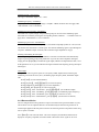
An Introduction to the SCPI Language
SCPI (Standard Commands for Programmable Instruments) is an ASCII-based instrument
command language designed for test and measurement instruments. SCPI commands are based on
a hierarchical structure, also known as a tree system. In this system, associated commands are
grouped together under a common node or root, thus forming subsystems. A portion of the
SOURCE subsystem is shown below to illustrate the tree system.
SOURce:
FREQuency:
STARt {<frequency>|MINimum|MAXimum}
FREQuency:
STARt? [MINimum|MAXimum]
FREQuency:
STOP {<frequency>|MINimum|MAXimum}
FREQuency:
STOP? [MINimum|MAXimum]
SOURce is the root keyword of the command, FREQuency is the second-level keywords, and
STARt and STOP are third-level keywords. A colon (: ) separates a command keyword from a
lower-level keyword.
Preparations for Remote Operation
The Arbitrary/Function Generator series 4080 can be remotely controlled from a PC via the
standard RS232 interface. Make sure to configure the RS232 interface to match the settings on your
PC by setting the parameters in the Systems menu accordingly. The instrument enters the remote
state after any remote command is received at which time all keys except of the【Local】key (Shift)
are locked When in Remote mode, the instrument can be returned to Local mode by pressing the
【Local】 key or by sending a “LOCAL instruction via the RS232 interface.
5.2 Overview and syntax of SCPI instructions
This section summarizes the SCPI commands available to program the function generator over the
remote interface. Refer to the later sections in this chapter for more details on each command.
Throughout this manual, the following conventions are used for SCPI command syntax.
•
Square brackets ([ ]) indicate optional keywords or parameters.
•
Braces ({ }) enclose parameters within a command string.
•
Triangle brackets (< >) indicate that you must substitute a value for the enclosed parameter.
•
A vertical bar (|) separates multiple parameter choices.
Command Summary
APPLY instruction
35
4080 series Arbitrary/Function Generator with Counter –Instruction Manual
APPLy:SINusoid [<frequency>, <amplitude>, <offset>]
APPLy:SQUare [<frequency>, <amplitude>, <offset>]
APPLy:TRIangle [<frequency>, <amplitude>, <offset>]
APPLy:UP_RAMP [<frequency>, <amplitude>, <offset>]
APPLy:DOWN_RAMP [<frequency>, <amplitude>, <offset>]
APPLy:NOISe [<frequency>*, <amplitude>, <offset>]
APPLy:P_DC [<frequency>,* <amplitude>, <offset>]
APPLy?
*: if waveform is Noise or DC, the frequency data contained in the command is not invalid.
OUTPUT instructions
[SOURce:]
FUNCtion SHAPe {SINusoid|SQUare|TRIangle|UP_RAMP|DOWN_RAMP|
NOISe|PULSe|P_PULSE|N_PULSE|P_DC|N_DC|STAIR|
C_PULSE|COMMUT_FU|COMMUT_HA|SINE_TRA|
SINE_VER|SINE_PM|LOG|EXP|ROUND_HAL|
SINX/X|SQU_ROOT|TANGent|CARDIO|QUAKE|COMBIN}
FUNCtion:SHAPe?
[SOURce:]
FREQuency <frequency>
FREQuency?
[SOURce:]
PULSe:DCYCle <percent>
PULSe:DCYCle?
[SOURce:]
VOLTage <amplitude>
VOLTage?
VOLTage: OFFSet <offset>
VOLTage: OFFSet?
[SOURce:]
OUTPut:LOAD {50|INFinity}
OUTPut:LOAD?
INPUT:FILTER <on|off>
INPUT:FILTER?
INPUT:ATTenuator <on|off>
INPUT:ATTenuator?
*SAV {0|1|2|3|4|5|6|7|8|9|10}. State 0 is the working state of the instrument before power off
*RCL {0|1|2|3|4|5|6|7|8|9|10}. States 1—10 are user defined working states
MODULATION instructions
[SOURce:]
AM:DEPTh <depth in percent>
AM:DEPTh?
AM:INTernal:FUNCtion {SINusoid|SQUare|TRIangle|UP_RAMP|DOWN_RAMP|}
AM:INTernal:FUNCtion?
36
4080 series Arbitrary/Function Generator with Counter –Instruction Manual
AM:INTernal:FREQuency <frequency>
AM:INTernal:FREQuency?
AM:SOURce {INTernal|EXTernal}
AM:SOURce?
AM:STATe {ON|OFF}
AM:STATe?
[SOURce:]
FM:DEViation <peak deviation in Hz>
FM:DEViation?
FM:INTernal: FUNCtion {SINusoid|SQUare|TRIangle|UP_RAMP|DOWN_RAMP|……}
FM:INTernal: FUNCtion?
FM:INTernal: FREQuency <frequency>
FM:INTernal: FREQuency?
FM:SOURce {INTernal|EXTernal}
FM:SOURce?
FM:STATe {ON|OFF}
FM:STATe?
[SOURce:]
BM:NCYCles <#cycles>
BM:NCYCles?
BM:PHASe <degrees>
BM:PHASe?
BM:INTernal: Space <time in second>
BM:INTernal: Space?
BM:SOURce {INTernal|EXTernal|SINGle}
BM:SOURce?
BM:STATe {ON|OFF}
BM:STATe?
FSK instructions
[SOURce:]
FSKey:FREQuency <frequency>
FSKey:FREQuency?
FSKey:INTernal: Space <time in second>
FSKey:INTernal: Space?
FSKey:SOURce {INTernal|EXTernal}
FSKey:SOURce?
FSKey:STATe {ON|OFF}
FSKey:STATe?
PSK instructions
[SOURce:]
PSKey:PHASe1 <degrees>
PSKey:PHASe1?
PSKey:PHASe2 <degrees>
PSKey:PHASe2?
PSKey:INTernal: Space <time in second>
PSKey:INTernal: Space?
37
4080 series Arbitrary/Function Generator with Counter –Instruction Manual
PSKey:SOURce {INTernal|EXTernal}
PSKey:SOURce?
PSKey:STATe {ON|OFF}
PSKey:STATe?
SWEEP instructions
[SOURce:]
FREQuency:STARt <frequency>
FREQuency:STARt?
FREQuency:STOP <frequency>
FREQuency:STOP?
[SOURce:]
SWEep:SPACing {LINear|LOGarithmic}
SWEep:SPACing?
SWEep:TIME <time in second>
SWEep:TIME?
SWEep:SOURce {INTernal|EXTernal}
SWEep:SOURce?
SWEep:STATe {ON|OFF}
SWEep:STATe?
COUNT instructions
[SOURce:]
FUNCtion:TOTal INITial
FUNCtion:TOTal STARt
FUNCtion:TOTal STOP
FUNCtion:TOTal CLEAr
FUNCtion:TOTal?
FREQUENCY MEASUREMENT instructions
[SOURce:]
FUNCtion:FREQuency MEASure
FUNCtion:FREQuency?
FUNCtion:FREQuency GATE <time>
FUNCtion:FREQuency GATE?
TRIGGER instructions
TRIGger:SOURce {IMMediate|EXTernal|BUS}
TRIGger:SOURce?
SYSTEM instructions
38
4080 series Arbitrary/Function Generator with Counter –Instruction Manual
*IDN?
*RST
*SAV {0|1|2|3|4|5|6|7|8|9|10}
*RCL {0|1|2|3|4|5|6|7|8|9|10}
RS232 specific instructions
SYSTem:LOCAL
SYSTem:REMOTE
5.3 Detailed description of SCPI Instructions
APPLy instructions
APPLy instructions are used to directly set the output of the function generator through the remote
interface including waveform, frequency and offset. For example, to output a sine wave of 5kHz,
3Vp-p with –2.5V DC offset, the following commands need to be sent:
“APPL:SIN 5 KHZ, 3.0 VPP, -2.5 V”
“APPL:SIN 5.0E+3,3.0, -2.5”
Instructions of lower level can also be used:
“FUNC:SHAPE SIN”, to output a sine wave
“FREQ 5.0 KHZ”, to set frequency as 5kHz
“VOLT 3.0”, to set voltage as 3 VPP
“VOLT:OFFSET -2.5”, to set output offset as -2.5 V
APPLy?
Queries the waveform, frequency, amplitude and offset of current function output. The returned data
format is:
“SIN 5.000000000000E+03, 3.000000E+00, -2.500000E+00”
OUTPUT instructions
FUNCtion:SHAPe {SINusoid|SQUare|TRIangle|UP_RAMP|DOWN_RAMP|NOISe……}
Select output waveform. 27 waveforms are available. In fixed frequency mode, each of the 27 kinds
can be selected. In other modes, only sine and square waves can be selected.
FUNCtion:SHAPe?
Check the waveform of current function output. The returned data are SIN, SQU, TRI, UP_RAMP,
etc.
FREQuency <frequency>
Set the frequency of function output
FREQuency?
Check the frequency of current main function output. The returned data unit is Hz.
PULSe:DCYCle <percent>
Set the duty cycle of pulse output.
Duty cycle: 0.1%—99.9%, in step of 0.1% (f ≤ 10 KHz)
1%—99% in step of 1% (10 kHz < f ≤ 100 kHz), default value 20%.
PULSe:DCYCle?
Check the duty cycle of current pulse output. The returned value is percentage.
VOLTage <amplitude>
39
4080 series Arbitrary/Function Generator with Counter –Instruction Manual
Set the amplitude of the currently active waveform. The amplitude setting should be consistent with
the technical specifications. The output amplitude ranges of P_PULSE, N_PULSE, P_DC and
N_DC should be 2mVpp ≤ ampl ≤ 10Vpp in high impedance output setting and 1mVpp ≤ ampl ≤
5Vpp in 50Ω setting. The above value is given based on a DC offset of 0V. If a DC offset is used,
refer to the setting of DC offset described in Chapter 4 in this manual
VOLTage?
Check the output amplitude of current main function output.
VOLTage OFFSet <offset>
Set the DC offset. For the relationship between the DC offset and output amplitude, refer to section
4.5.3.
VOLTage OFFSet?
Check the DC offset of main function output.
OUTPut:LOAD {50|INFinity}
Configure the amplitude display value for 50Ω or high impedance (INFinity) load termination. The
output amplitude should be consistent with the technical specifications.
OUTPut:LOAD?
Read the current load impedance setting of the function generator.
INPUT: FILTER {ON|OFF}
Enable/disable the low pass filter for the counter
INPUT:FILTER?
Read the current “on/off” state of the low pass filter.
INPUT:ATTenuator {ON|OFF}
Enable/disable Set the input attenuator of the counter
INPUT:ATTenuator?
Read the state of the input attenuator (on/off)
*SAV {0|1|2|3|4|5|6|7|8|9|10}
Save as many as 11 input states of the instrument. Among the 11 states, state 0 is used to
automatically store the power off setting of the instrument. States 1~10 are user defined.
*RCL {0|1|2|3|4|5|6|7|8|9|10}
Recall one of the states 0 -10.
AM instructions
1.To set the carrier of output using APPLy instructions or FUNCtion, FREQuency, VOLTage,
VOLTAGE: OFFSet instructions.
2.To set modulating waveform of AM using AM:INTernal: FUNCtion
{SINusoid|SQUare|TRIangle……} instructions
3.To set modulating frequency of AM using AM: INTernal: FREQuency <frequency> instructions.
4.To set the modulation depth of AM using AM: DEPTh {depth in percent} instructions
5.To set modulating source of AM using AM: SOURce {INTernal|EXTernal} instructions
6.To start AM using AM: STATe ON instructions.
AM: DEPTh {depth in percent}
Set modulation depth of AM. MIN=1%, MAX=120%.
AM: DEPTh?
40
4080 series Arbitrary/Function Generator with Counter –Instruction Manual
Read the current modulation depth of AM.
AM:INTernal:FUNCtion {SINusoid|SQUare|TRIangle……}
Set the modulating waveform for AM,using modulating waveforms SIN, SQU, TRI UP, RAMP and
DOWN_RAMP.
AM:INTernal:FUNCtion?
Check current modulating waveform of AM. Return parameters are “SIN”, “SQU”, TRI”,
“UP_RAMP”, “DOWN_RAMP”
AM:INTernal: FREQuency <frequency>
Set frequency of modulating signal of AM. When internal modulating source is selected, the
modulating frequency should be≤10kHz.
AM:INTernal:FREQuency?
Read the frequency of the current modulating signal for AM.
AM:SOURce {INTernal|EXTernal}
Set modulating source of modulating signal of AM as internal (INTernal) or external (EXTernal).
AM:SOURce?
Read the current modulating source of AM.
AM:STATe {ON|OFF}
Turn AM mode on/off
AM:STATe?
Check the “on/off” state of AM mode. The returned data are “0” (OFF) or “1” (ON).In “off” state,
the instrument reverts back to fixed frequency mode.
FM instructions
1.To set the carrier of output using APPLy or FUNCtion, FREQuency, VOLTage, VOLTAGE:
OFFSet instructions.
2.To set modulating waveform of FM using FM: INTernal: FUNCtion
{SINusoid|SQUare|TRIangle……} instructions
3.To set modulating frequency of FM using instruction FM:INTernal: FREQuency <frequency>
4.To set the modulating deviation of FM using instruction FM: DEViation <peak deviation in Hz>
5.To set modulating source of FM using the FM: SOURce {INTernal|EXTernal} instruction
6.To start FM using FM: STATe ON instruction.
FM:DEViation <peak deviation in Hz>
Set the modulating deviation of FM. The maximum value should be half of carrier frequency in
internal modulating source and 10% of carrier frequency in external modulating frequency. (Should
also satisfy the following equation: Fc + Fd <= Fmax+100khz
FM:DEViation?
Read the current modulating deviation of FM.
FM:INTernal:FUNCtion {SINusoid|SQUare|TRIangle……}
Set the modulating waveform of FM using SIN, SQU, TRI UP, RAMP or DOWN_RAMP waveforms.
FM:INTernal:FUNCtion?
Read the current modulating waveform of FM. The returned data are “SIN”, “SQU”, “TRI”,
“UP_RAMP”, “DOWN_RAMP”.
41
4080 series Arbitrary/Function Generator with Counter –Instruction Manual
FM:INTernal:FREQuency <frequency>
Set the frequency of modulating signal of FM. The modulating frequency should be ≤10KHz when
internal modulating source is selected.
FM:INTernal:FREQuency?
Read the frequency of current modulating signal of FM.
FM:SOURce {INTernal|EXTernal}
Set modulating source of FM signal as internal (INTernal) or external (EXTernal).
FM:SOURce?
Read the current modulating source of FM.
FM:STATe {ON|OFF}
Turn on FM mode (ON), turn off FM mode (OFF).
FM:STATe?
Check the “on/off” state of FM mode. The returned data are “0” (OFF) or “1” (ON). It returns to
fixed frequency mode in “off” state.
Burst Mode instructions
1. Set the carrier using APPLy instructions or FUNCtion, FREQuency, VOLTage, VOLTAGE:
OFFSet instruction.
2. Set number of burst using BM: NCYCles <#cycles> instruction.
3. Set start phase of burst using BM: PHASe <degrees> instruction.
4. Set time interval between two bursts using BM:INTernal: SPACe <time> instruction.
5. Set trigger source of burst using BM: SOURce {INTernal|EXTernal|SINGle} instruction.
6. To turn on burst use the BM: STATe ON instruction.
BM:NCYCles <#cycles>
Set waveform numbers of burst. MAX≤10000.
BM:NCYCles?
Check number of bursts.
BM:PHASe <degrees>
Set start phase of burst in 0—360º in step of 0.1º.
BM:PHASe?
Check the start phase of burst.
BM:INTernal: SPACe <time>
Set time interval between two bursts.
BM:INTernal: SPACe?
Check time interval between two bursts.
BM:SOURce {INTernal|EXTernal|SINGle}
Set trigger source of burst as internal (INTernal), external (EXTernal) or single (SINGle).
BM:SOURce?
Check current trigger source of burst.
BM:STATe {ON|OFF}
Turn on burst mode (ON) or turn off burst mode (OFF).
BM:STATe?
42
4080 series Arbitrary/Function Generator with Counter –Instruction Manual
Check “on/off” state of burst mode. The returned data are “0” (OFF) or “1” (ON). The instrument
reverts back to fixed frequency mode in “off” state.
FSK Mode instructions
1.To set the output waveform, amplitude, DC offset and frequency 1 using APPLy instructions or
FUNCtion, FREQuency, VOLTage, VOLTAGE:OFFSet instructions.
2.set frequency 2 of FSK using FSKey: FREQuency <frequency> instruction.
3.set time interval of frequency switching using FSKey:INTernal: SPACe <time> instruction.
4.set trigger source of FSK using FSKey: SOURce {INTernal|EXTernal} instructions.
5.turn on FSK using FSKey: STATe ON instruction.
FSKey:FREQuency <frequency>
Set frequency 2 of FSK.
FSKey:FREQuency?
Check frequency 2 of FSK.
FSKey:INTernal:SPACe <time>
Set time interval of frequency switching
FSKey:INTernal:SPACe?
Check time interval of frequency switching
FSKey:SOURce {INTernal|EXTernal}
Set trigger source of FSK as internal (INTernal) or external (EXTernal).
FSKey:SOURce?
Check current trigger source of FSK.
FSKey:STATe {ON|OFF}
Turn on FSK mode (ON) or turn off FSK mode (OFF).
FSKey:STATe?
Check the “on/off” state of FSK mode. The returned data are “0” (OFF) or “1” (ON). It returns to
fixed frequency mode in “off” state.
PSK Mode instructions
1. To set the output waveform, amplitude, DC offset and frequency using APPLy instructions or
FUNCtion, FREQuency, VOLTage, VOLTAGE:OFFSet instructions.
2. To set phase 1of PSK using PSKey: PHASe1 <degrees> instruction.
3. To set phase 2 of PSK using PSKey: PHASe2 <degrees> instruction.
4. To set time interval of phase switching using PSKey:INTernal: SPACe <time> instruction.
5. To set trigger source of PSK using PSKey: SOURce {INTernal|EXTernal} instructions.
6. To turn on PSK using PSKey: STATe ON instruction.
FSKey:PHASe1 <degrees>
Set phase 1 of PSK in 0--360º.
PSKey:PHASe1?
Check phase 1of PSK
PSKey:PHASe2 <degrees>
Set phase 2 of PSK in 0--360º.
PSKey:PHASe2?
Check phase 2 of PSK.
43
4080 series Arbitrary/Function Generator with Counter –Instruction Manual
PSKey:INTernal:SPACe <time>
Set time interval of phase switching
PSKey:INTernal:SPACe?
Check time interval of phase switching
PSKey: SOURce {INTernal|EXTernal}
Set trigger source of PSK as internal (INTernal) or external (EXTernal).
PSKey:SOURce?
Check current trigger source of PSK.
PSKey:STATe {ON|OFF}
Turn on PSK mode (ON) or turn of f PSK mode (OFF).
PSKey:STATe?
Check the “on/off” state of PSK mode. The returned data are “0” (OFF) or “1” (ON). It returns to
fixed frequency mode in “off” state.
Sweep Mode instructions
1. To set the output waveform, amplitude, DC offset and frequency using APPLy instructions or
FUNCtion, FREQuency, VOLTage, VOLTAGE:OFFSet instructions.
2. To set start frequency of sweep using FREQuency: STARt <frequency> instruction.
3. To set stop frequency of sweep using P FREQuency: STOP<frequency> instruction.
4. To set sweep mode using SWEep: SPACing {LINear|LOGarithmic} instruction.
5. To set sweep time using SWEep: TIME <time> instructions.
6. To set trigger source of sweep using SWEep: SOURce {INTernal|EXTernal}instructions.
7. To turn on sweep using SWEep: STATe ON instruction.
FREQuency:STARt <frequency>
Set start frequency of sweep.
FREQuency:STARt?
Check startting frequency of sweep.
FREQuency:STOP <frequency>
Set stop frequency of sweep.
FREQuency:STOP?
Check stop frequency of sweep.
SWEep:SPACing {LINear|LOGarithmic}
Set sweep mode as linear (LINear) or logarithmic (LOGarithmic)
SWEep:SPACing?
Check sweep mode.
SWEep:TIME <time>
Set sweep time.
SWEep:TIME?
Check the sweep time.
SWEep:SOURce {INTernal|EXTernal}
Set trigger source of sweep as internal (INTernal) or external (EXTernal).
SWEep:SOURce?
44
4080 series Arbitrary/Function Generator with Counter –Instruction Manual
Check current trigger source.
SWEep:STATe {ON|OFF}
Turn on sweep mode (ON) or turn off sweep mode (OFF).
SWEep:STATe?
Check the “on/off” state of sweep mode. The returned data are “0” (OFF) or “1” (ON). It returns to
fixed frequency mode in “off” state.
Counting instructions
FUNCtion:TOTal INITial
Initialize the counter.
FUNCtion:TOTal STARt
Set the counter to start counting.
FUNCtion:TOTal STOP
Set the counter to stop counting.
FUNCtion:TOTal CLEAr
Clear the counted value of the counter.
FUNCtion:TOTal?
Record the current value of the counter.
Frequency Measurement instructions
FUNCtion:FREQuency MEASure
Enable frequency measurement function for the instrument to start a new frequency measurement.
FUNCtion:FREQuency?
Record last frequency value after frequency measurement is finished.
FUNCtion:FREQuency GATE <time>
Set gate time in the range of 10ms to 10s for frequency measurement.
FUNCtion:FREQuency GATE?
Check current gate time for frequency meadurement.
Trigger instructions
TRIGger:SOURce {IMMediate|EXTernal|BUS}
Set trigger source or modulating source for available functions as internal (IMMediate), external
(EXTernal) or single (BUS).
TRIGger:SOURce?
Check trigger source or modulating source of current function as internal (IMM), external, (EXT)
or single (BUS).
System related instructions:
*IDN?
This query will return the instrument’s manufacturer, model number and firmware version.
Example: B+K Precision 4084AWG V1.00
*RST
Reset instrument to the default state
*SAV {0|1|2|3|4|5|6|7|8|9|10}
Save as many as 11 input states of the instrument. Among the 11 states, state 0 is used to
automatically store the power off setting of the instrument. States 1~10 are user defined.
45
4080 series Arbitrary/Function Generator with Counter –Instruction Manual
*RCL {0|1|2|3|4|5|6|7|8|9|10}
Recall on of the states 0 -10.
Special instructions for RS232
SYSTem:LOCAL
This instruction causes the instrument to enter into local state. After receipt of this command, all
front panel keys are enabled.
SYSTem:REMOTE
This instruction causes the instrument enter remote state from local state. After receipt of this
command, all front panel keys are disabled except of the local key (shift key) which can be used to
manually revert to local state.
NOTE: All command strings send to the instrument must terminate with a <new
line> character. (0x0A or “\n”).
Wiring diagram of RS232 cable required for remote control (null modem configuration)
1
2
3
4
5
6
7
8
9
1
2
3
4
5
6
7
8
9
DB9 connector
DB9 connector
46
4080 series Arbitrary/Function Generator with Counter –Instruction Manual
6. USER PROGRAMMABLE ARBITRARY WAVEFORM
MODULE
Product Overview
In addition to the 27 build-in waveforms, models 4084AWG and 4086AWG also provide the
capability to generate and store up to 8 user-defined waveforms in non-volatile memory.
This Windows-based software tool offers a graphical user interface that you can use to create, edit,
and transfer custom waveforms to the internal memory of the 4084AWG or 4086AWG
Function/Arbitrary Generator.
Waveforms can be created in several ways: Users can draw new waveforms with a mouse, edit one
of the predefined waveforms, read in waveform parameters from a text file or download waveforms
from a TEKTRONIX® digital storage oscilloscope. Once completed, the waveform can be
transmitted to the generator and stored in non-volatile memory.
Software Installation
This section describes how to install the Arbitrary Waveform Creation Software using the Install
Shield Wizard.
1) Insert the Installation CD into the CD-ROM drive.
2) Locate setup.exe on the CD-ROM and double-click it.
3) Follow the instructions given by the Install Shield wizard.
Launching the Software
To start the Software you can do one of the following:
a) Run the application from the Windows Start menu.
Select Start> Programs> BK_Precision>4080 Series Arbitrary Waveform
Software\Arb_Process.exe
b) Go to the folder where you have installed the Arbitrary Waveform Creation Software and
double-click on Arb_process.exe.
To exit the application, select File > Exit from the pull down menu
47
4080 series Arbitrary/Function Generator with Counter –Instruction Manual
CREATING AND EDITING WAVEFORMS
Create waveforms by loading waveform data from a text file or by using the graphical tools of this
Software.
Working with text files
Waveforms can be imported to or exported from a text file with the following format:
The first line contains the number of data points, the consecutive lines the Y axis value of the
sampling points.
Example wave1.txt:
8
(Line 1:length of the waveform)
-0.666
(Line 2:waveform value of point 0)
-0.555
(Line 3:waveform value of point 1)
-0.111
(Line 4:waveform value of point 2)
0.001
(Line 5:waveform value of point 3)
0.123
(Line 6:waveform value of point 4)
0.235
(Line 7:waveform value of point 5)
0.378
(Line 8:waveform value of point 6)
0.654
(Line 9:waveform value of point 7)
Only use text editors such as NOTEPAD to create or edit this file.
Saving and opening text files
To save the current waveform as a text file, Select File>Save to and enter a filename. To import
waveform data, select “Open” from the File menu. The waveform data will be automatically
displayed in the editing window.
48
4080 series Arbitrary/Function Generator with Counter –Instruction Manual
Working with graphical tools
Waveform Parameters
The waveform parameters are represented in the following format: Values of the vertical axis (Y)
are normalized to -1.000 ~ 1.000. Values of the horizontal axis (X axis) are 0 ~ length of waveform
minus 1.
Setting the number of points
The waveform length can be set as required. Input the required number of points in the waveform
setup area then press ENTER. The X-axis will be updated accordingly. The minimum number of
points is 8, the maximum number is 16000.
Drawing waveforms
Click on the left mouse key then grab and move the default center line to the desired location.
The coordinates of the cursor position will be displayed while “drawing”. Release the left
mouse key to stop drawing.
49
4080 series Arbitrary/Function Generator with Counter –Instruction Manual
Clearing the waveform
To clear all waveforms in the editing area, click the “Clear” waveform button.
Zoom function
To enlarge an area of the waveform, click on the “zoom in” symbol then use the scroll bar below the
editing window to view the desired area. You can also use View>Zoom in. To zoom out, click on the
“zoom out” symbol on the tool bar or select use View>Zoom.
Click the “1:1”symbol to restore the default view.
Direct waveform entry
Accurate input of point values
Define a point by entering the (X) and (Y) coordinates in the start point field then click “Set point”
to complete the entry. The value of this point will be recorded and displayed in the drawing area.
Accurate input of line segments
To define a straight line segment, enter the corresponding (X) and (Y) coordinates of the starting
point of this line segment in the “start point” field. Enter the (X) and (Y) coordinates for the stop
point of the line in the”stop point” field. Click “set line”. The value of this line segment will be
automatically calculated and displayed in the drawing area.
Generating standard waveform
6 standard waveforms can be generated:square,sine,cosine,triangle,rising and falling ramp.
Select a waveform from the standard waveforms menu. The waveform will be displayed
immediately in the editing window.
50
4080 series Arbitrary/Function Generator with Counter –Instruction Manual
Modifying existing waveforms with mathematical Functions
Waveforms can be modified by applying one of the following mathematical functions: Addition,
subtraction of waveforms, symmetry of Y-axis and X-axis, division and multiplication by a
constant.
Add
Add waveform data stored in a text file to the current waveform (displayed on the screen). The
51
4080 series Arbitrary/Function Generator with Counter –Instruction Manual
resulting new waveform is automatically normalized by dividing the new waveform by 2. To look
at it differently, each amplitude value is weighted by a factor 0.5 before the add operation is
performed.
If the lengths of the two waveforms differ, the longer length is taken as the length of the new
waveform.
Subtract
Subtract waveform data stored in a text file from the current waveform (displayed on the screen).
The resulting new waveform is automatically normalized by dividing the new waveform by 2. To
look at it differently, each amplitude value is weighted by a factor 0.5 before the subtract operation
is performed.
If the lengths of the two waveforms differ, the longer length is taken as the length of the new
waveform.
Symmetry of waveform X-axis
Flip the current image around the X-axis to create a mirror image of the previous waveform.
Symmetry of waveform Y-axis
Flip the current image around the vertical center line, which divides the editing screen in half.
Amplitude Divide
Divide the amplitude of the current waveform by an integer value. The value can be positive or
negative (but not zero)
Amplitude multiply
Multiply the amplitude of the current waveform by an integer value. The value can be positive or
negative (but not zero)
Frequency multiply
Multiply the timebase value of the current waveform by an integer value. The value must be
positive (but not zero). An integer value of 2 will double the frequency
Formula of sine add
Add 2 sine waves according to the predefined formula 1*sin(x) + a*sin (b*x). Choose parameters a
and b. The first sine wave in the equation cannot be edited.
52
4080 series Arbitrary/Function Generator with Counter –Instruction Manual
TRANSFERING WAVEFORM DATA TO THE 408XAWG
RS232 communication setup
1) Connect the computer to the 4084AWG or 4086AWG using the RS232 cable included.
2) Set the RS232 parameters of the Arbitrary Waveform Creation Tool
3) Set the RS232 parameters in the Systems menu of the 4080 series generator. Make sure the
“COM port”, “Baud rate” and “parity” and Flow control parameters match that of the Software
settings.
Select a memory location
Models 4084AWG and 4086AWG offer 8 memory locations for storing user defined arbitrary
waveforms. Numbers 1 – 8 in the waveform number field of the software correspond to “ARB1” –
“ARB8” on the instrument side which are located at positions 28 to 35 on the Arblist (see chapter 4,
section 3).
Arblist location
28
29
30
31
32
33
34
35
Press <Shift> +
1
2
3
4
5
6
7
8
Display Name
ARB1
ARB2
ARB3
ARB4
ARB5
ARB6
ARB7
ARB8
Transfer of waveform in current editing area
Initiate a waveform transfer to the 4080 series generator by clicking the “Send Data” button or
Selecting Other>Send Data from the menu. A pop-up window will indicate the progress of the data
transfer. The window will automatically disappear once the data was downloaded successfully. If
53
4080 series Arbitrary/Function Generator with Counter –Instruction Manual
the download was unsuccessful due to communication problems, a pop message will appear
prompting the user to verify the setup and settings of the communication link.
Example:
Draw a waveform with a 1024 point length and transfer the data to memory location “ARB1”.
1) Connect the computer and the instrument using the supplied RS232 cable and configure the
RS232 parameters on the instrument and software side. Make sure the parameters match
2) Set waveform length as 1024 points.
3) Create a waveform
4) Set “Waveform Number” to 1
5) Click on the “Send Data” button
6) After the transfer completed successfully, press [Shift][Shift] [1] on the instrument to select
and enable waveform “ARB1” (the first Shift key press puts the instrument into Local
mode)
Note: If ARB1 was already enabled, the output of the generator will be updated immediately with
the new waveform data as soon as the download is complete
READING DATA FROM A TEKTRONIX® DIGITAL STORAGE
OSCILLOSCOPE
This tool allows the direct transfer of waveform data from a Tektronix digital storage oscilloscope to
this Software. The data can originate from the oscilloscope’s screen display (channel 1 or channel 2)
or internal memory where the reference waveform from channel 1 or 2 is stored. The Software is
compatible with TDS1000, TDS2000, TPS2000 and TDS3000 series oscilloscopes equipped with a
RS232 interface.
Download instructions:
1) Connect the computer and digital storage oscilloscope (DSO) using an RS232 cable.
2) Set the communications parameters for the DSO. Refer to the oscilloscope’s manual for
setup instructions. Make sure that the RS232 parameters under “menu RS232 set” match
that of the Arbitrary waveform Creation Software. Additionally set the “EOL” or “End of
Line” string in the oscilloscopes menu. Supported termination strings are <CR>, LF or a
combination of the two, <CR><LF> or <LF><CR>
3) Set the RS232 parameters and EOL string on the Software side. Make sure parameters
“communications address”, “Baud rate”, “parity”, “flow control” and“EOF character
string” matches that of the oscilloscope settings.
54
4080 series Arbitrary/Function Generator with Counter –Instruction Manual
4) Click “Set Link” in the “oscilloscope” menu of the software to check the communications
link between software and oscilloscope. A pop-up window will indicate successful
communication; otherwise, the operation will result in an error message. This operation
will also automatically populate the waveform length field based on the oscilloscope’s
internal storage memory.
5) Select the Source of the data to be read from the oscilloscope
6) Select the desired data source from oscilloscope menu>Source. Refer to your
oscilloscope’s user manual for data sources available.
7) Read the oscilloscope data from the source selected: Click on “read data” in sub-menu
oscilloscope”. A pop-up window will appear to display the current status of the transfer.
The pop up window will automatically disappear once transmission was completed
successfully and the downloaded data will automatically be displayed in the Software’s
editing window.
55
4080 series Arbitrary/Function Generator with Counter –Instruction Manual
Requirement for RS232 cable connecting the TEKTRONIX oscilloscope and 408xAWG
Refer to the oscilloscope’s instruction manual. For the TEKTRONIX series digital storage
oscilloscopes, a null modem (cross over) using 2 handshake lines is recommended.
1
2
3
4
5
6
7
8
9
1
2
3
4
5
6
7
8
9
56
4080 series Arbitrary/Function Generator with Counter –Instruction Manual
7. APPENDIX
Responsible Party
Manufacturer’s
Name:
Manufacture’s
Address:
Alternate Manufacturing Site
B&K Precision Corporation
B&K China 1364
22820 Savi Ranch Pkwy.
Yorba Linda, CA 92887-4610
USA
Declares that the below mentioned product
Product Name: Function/ Arbitrary Generator with Counter
Part Numbers: 4084, 4084AWG, 4085, 4086, 4086AWG, 4087
complies with the essential requirements of the following applicable European Directives:
Low Voltage Directive 73/23/EEC (19.02.73) amended by 93/68/EEC
(22.07.93) Electromagnetic Compatibility (EMC) 89/336/EEC (03.05.88)
amended by 92/68/EEC (22.07.93)
and conforms with the following product standards:
LVD
EN61010-1:2001, EN61010-031:2002
EMC
EN61326: 1997+A1: 1998+A2: 2001+A3: 2003
EN55022: 1998+A1:2000+A2
EN61000-3-2: 2000
EN61000-3-3: 1995+A1:2001
EN55024: 1998+A1: 2001+A2:2003
This Declaration of Conformity applies to above listed products place on the EU market after:
January 31 2007
Date
Victor Tolan
President
57
4080 series Arbitrary/Function Generator with Counter –Instruction Manual
Service Information
Warranty Service: Please return the product in the original packaging with proof of purchase to the address below.
Clearly state in writing the performance problem and return any leads, probes, connectors and accessories that you
are using with the device.
Non-Warranty Service: Return the product in the original packaging to the address below. Clearly state in writing
the performance problem and return any leads, probes, connectors and accessories that you are using with the device.
Customers not on open account must include payment in the form of a money order or credit card. For the most
current repair charges please visit www.bkprecision.com and click on “service/repair”.
Return all merchandise to B&K Precision Corp. with pre-paid shipping. The flat-rate repair charge for Non-Warranty
Service does not include return shipping. Return shipping to locations in North American is included for Warranty
Service. For overnight shipments and non-North American shipping fees please contact B&K Precision Corp.
B&K Precision Corp.
22820 Savi Ranch Parkway
Yorba Linda, CA 92887
www.bkprecision.com
714-921-9095
Include with the returned instrument your complete return shipping address, contact name, phone number
and description of problem.
Limited One-Year Warranty
B&K Precision Corp. warrants to the original purchaser that its products and the component parts thereof, will be
free from defects in workmanship and materials for a period of one year from date of purchase.
B&K Precision Corp. will, without charge, repair or replace, at its option, defective product or component parts.
Returned product must be accompanied by proof of the purchase date in the form of a sales receipt.
To obtain warranty coverage in the U.S.A., this product must be registered by completing a warranty registration
form on www.bkprecision.com within fifteen (15) days of purchase.
Exclusions: This warranty does not apply in the event of misuse or abuse of the product or as a result of
unauthorized alterations or repairs. The warranty is void if the serial number is altered, defaced or removed.
B&K Precision Corp. shall not be liable for any consequential damages, including without limitation damages
resulting from loss of use. Some states do not allow limitations of incidental or consequential damages. So the above
limitation or exclusion may not apply to you.
This warranty gives you specific rights and you may have other rights, which vary from state-to-state.
B&K Precision Corp.
22820 Savi Ranch Parkway
Yorba Linda, CA 92887
www.bkprecision.com
714-921-9095
58
4080 series Arbitrary/Function Generator with Counter –Instruction Manual
Intentionally left blank
59
4080 series Arbitrary/Function Generator with Counter –Instruction Manual
22820 Savi Ranch Parkway
Yorba Linda, CA 92887
www.bkprecision.com
© 2007 B&K Precision Corp.
Printed in China
Edition 1.0
60