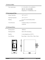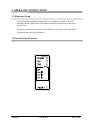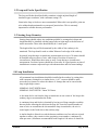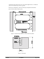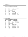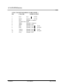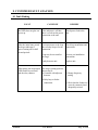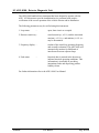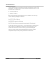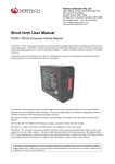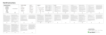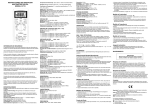
1
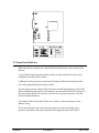
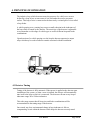
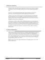
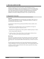
This document is for information only and unless
otherwise indicated it is not to form part of any
contract.
In accordance with the manufacturer’s policy of
continually updating and improving design,
specifications contained herein are subject to
alterations without notice.
AGP-0230
USER MANUAL
AMANO
Copyright © 1996
Document No. : 302UM0003-00
Date of issue : March 1996
Table of Contents
1. INTRODUCTION................................................................................................
1
2. TECHNICAL DATA............................................................................................
2.1 Functional Data....................................................................................................
2.2 Electrical Data......................................................................................................
2.3 Functional Data....................................................................................................
2.4 Mechanical Data..................................................................................................
2
2
3
3
3
3. OPERATING INSTRUCTIONS.........................................................................
3.1 Hardware Set-up..................................................................................................
3.2 Switching Setting Selections...............................................................................
3.2.1 Frequency Switching......................................................................................
3.2.2 Sensitivity........................................................................................................
2.3.3 Automatic Sensitivity Boost............................................................................
2.3.4 Presence Time.................................................................................................
2.3.5 Reset Switch....................................................................................................
2.3.6 Internal Link Selection....................................................................................
3.3 Front Panel Indicator...........................................................................................
4
4
5
5
5
6
6
6
6
7
4. PRINCIPLE OF OPERATION........................................................................... 8
4.1 Detector Tuning................................................................................................... 8
4.2 Detector Sensitivity.............................................................................................. 9
4.3 Modes of Operation............................................................................................. 9
4.4 Response Time..................................................................................................... 10
5. INSTALLATION GUIDE
5.1 Operational Constraints.......................................................................................
5.2 Loop and Feeder Specifications..........................................................................
5.3 Sensing Loop Geometry......................................................................................
5.4 Loop Installation..................................................................................................
11
11
12
12
12
6. CONFIGURATION.............................................................................................
6.1 AGP-0231 Detector.............................................................................................
6.2 AGP-0232 Detector.............................................................................................
6.3 AGP-0234 Detector.............................................................................................
15
15
15
16
7. APPLICATIONS..................................................................................................
17
8. CUSTOMER FAULT ANALYSIS.....................................................................
8.1 Fault Finding........................................................................................................
8.2 ADU-0100 - Detector Diagnostic Unit................................................................
8.3 Functional Test....................................................................................................
18
18
19
20
AGP-0230
Page i
User Manual
SAFETY PRECAUTION : - Ensure that Electric
Power has been turned off before opening the unit.
AGP-0230
User Manual
Page ii
1. INTRODUCTION
The AGP-0230 is a dual channel microprocessor based detector designed specifically
for parking and vehicle access control applications. The AGP-0230 has been designed
using the latest technology in order to meet the requirements of a vast number of
parking applications in terms of operating conditions. A number of internal function
options are available to the user.
The primary function of the detector is to detect vehicle presence by means of an
inductance change caused by the vehicle passing over a wire loop buried under the
road surface.
The detector has been designed around the popular AGP-0130 series of single channel
detectors for ease of installation and convenience. The various modes are selected by
changing the position of switches on the front of the unit.
The detector oscillator is multiplexed to eliminate any possibility of crosstalk between
the loops connected to the detector.
The switches allow for different loop frequency settings, sensitivity settings and mode
settings.
The unit has a number of initial selectable options for configuration of the relay
outputs.
The AGP-0230 provides visual outputs ( LED ) on the front of the enclosure and relay
change-over contacts at the 11 pin connector at the rear of the enclosure. The power
LED indicates that the unit has been powered. The channel status LED’s below
indicate that a vehicle is present over the loop and when there is a fault on the loop.
The Presence relays are normally fail-secure and will close on a vehicle detect or loop
failure but not if there is a power failure.
AGP-0230
User Manual
Page 1 of 20
2. TECHNICAL DATA
2.1 Functional Data
Tuning
Fully automatic
Self-tuning range
20 to 1500µH
Sensitivity
Four step switch selectable
High 0.02% , L/L
Medium High 0.05% , L/L
Medium Low 0.10% , L/L
Low 0.50% , L/L
Frequency
Four step switch selectable
Frequency dependent on loop size
Automatic Sensitivity Boost Switch selectable
Modes
Output relays operate in the Presence ( fail-secure ),
Pulse or Direction logic modes
Presence Time
Switch selectable:
Limited presence
Permanent presence
Pulse Output Duration
150/250 millisecond options
Response Times
100 milliseconds
Drift Compensation Rate
Approx. 1% , L/L per minute
Visual Indication
1 x Power LED - Red
2 x Channel Status LED - Green
Relay Outputs
2 x Relays rated - 5A @ 230 VAC
Reset
Reset by push button on front of enclosure
Surge Protection
Loop isolation transformer, gas discharge tubes,
and Zener diode clamping on loop input
AGP-0230
User Manual
Page 2 of 20
2.2 Electrical Data
Power requirements
12 - 24V AC/DC ± 15% ( AGP-0234 )
120V AC ± 15% ( 48 to 60Hz )
230V AC ± 15% ( 48 to 60Hz )
Requirement: 1.5 VA Maximum at 230V
2.3 Environmental Data
Storage Temperature
-40°C to +85°C
Operating Temperature
-40°C to +85°C
Humidity
Circuit Protection
Up to 95% relative humidity without
condensation
Conformal coating over the PCB and all
components
2.4 Mechanical Data
Housing material
ABS blend
Mounting Position
Shelf or DIN rail mounting
Humidity
11-pin submagnal type ( 86CP11 )
Size of Housing
AGP-0230
76mm ( High ) x 39mm ( Wide ) x78mm ( Deep )
User Manual
Page 3 of 20
3. OPERATING INSTRUCTIONS
3.1 Hardware Set-up
The AGP-0230 dual channel parking detector is designed to be shelf or DIN rail
mounted with the controls and visual indicators at the front and wiring at the rear of
the enclosure.
The power, loop and relay outputs are all connected to the single 11-pin plug which
is mounted at the rear of the enclosure.
3.2 Switch Setting Selections
AGP-0230
User Manual
Page 4 of 20
3.2.1 Frequency Switch
The frequency switches are the lower two switches, numbered 1 and 2. There are four
frequency selections and are set out as follows:
SW2
Off
On
Off
On
SW1
Off - High
Off - Medium-High
On - Medium-Low
On - Low
The frequency switches allow the loop frequency to be shifted higher or lower
depending on the switch position. The frequency of the loop is determined by the loop
size, and the frequency of the switch simply causes a frequency shift on the loop.
Where more than one detector is used the detectors must be set-up to ensure that there
is no cross-talk (interference) between the detectors. This can be achieved by ensuring
that the loops of the two detectors are spaced sufficiently apart ( approximately 2
meters between adjacent edges ) and also ensuring that the detectors are set to
different frequencies. As a general rule, the detector connected to the inductive loop
with the greatest inductance should be set to operate at the lowest frequency. Loop
inductance increases as loop size, number of turns in the loop and feeder length
increases.
When the switch selection is altered, the frequency on both loops will change as the
unit is multiplexed and therefore use a common oscillator.
3.2.2 Sensitivity
The sensitivity of the detector allows the detector to be selective as to the change of
inductance necessary to produce an output. There are four sensitivity selections and are
set as follows: CH1
CH2
AGP-0230
SW6
SW4
Off
On
Off
On
SW5
SW3
Off
Off
On
On
-
User Manual
High
Medium-High
Medium-Low
Low
Page 5 of 20
3.2.3 Automatic Sensitivity Boost
Automatic sensitivity boost is a mode which alters the undetect level of the detector .
This mode is selected by switch No. 7 on the front of the enclosure and is set as
follows: SW7
Off
On
-
Disabled
Enabled
Automatic sensitivity boost causes the sensitivity to be boosted to a maximum on
detection on the vehicle, and maintained at this level during the presence of the entire
vehicle over the loop. When the vehicle departs the loop and detection is lost the
sensitivity reverts to the pre-selected level.
3.2.4 Presence Time
The presence time may be set to permanent presence or to limited presence. In
permanent presence mode the detector will continuously compensate for all
environmental changes whilst there is a vehicle present over the loop. In limited
presence mode there will be a finite time that the detector will remain in detect. This
time is dependent on the change of inductance that the vehicle caused. The presence
mode is set with switch No. 8 and is set as follows: SW8
Off
On
-
Limited Presence
Permanent Presence
3.2.5 Reset Switch
The detector automatically tunes to the inductive loops connected to it when power is
applied, whether on initial installation or after any break in the power supply. Should it
be necessary to retune the detector, as may be required after the changing of any
switch selections or after moving the detector from one installation to another,
momentary operation of the RESET switch will initiate to the automatic tuning cycle.
3.2.6 Internal Link Selection
There are 3 link positions located inside the AGP-0230 which are used to alter the
output relay configuration of the detector. The links have been placed inside the unit to
avoid incorrect operation due to selection by an unauthorised operator.
AGP-0230
User Manual
Page 6 of 20
3.3 Front Panel Indicator
While the detector is tuning, the Channel LED will indicate the “mode” status of the
detector.
i) Any Channel output operating in the presence or pulse modes will come on and
extinguish when the system is tuned.
ii) When the AB Logic mode is selected, the Channel LEDs will alternatively flash
slow and extinguish when the system is tuned.
If a loop fault exists the Channel LED will come on and flash indicating a fault. If the
fault is self-healing the detector will continue to operate and the LED will continue to
show the historical fault. The detector must be reset or power removed to clear the
historical fault information.
The channel LED will also glow whenever a vehicle is detected passing over the
inductive loop.
The Power LED at the top of the unit will remain on to indicate that the unit is
powered. This LED is also used as the link to the diagnostic unit ( ADU-0100 ).
AGP-0230
User Manual
Page 7 of 20
4. PRINCIPLE OF OPERATION
The inductive loop vehicle detector senses the presence of a vehicle over an area
defined by a loop of two or more turns of wire laid under the road or pavement
surface. This loop of wire is connected to the detector by a twisted pair of wires called
a loop feeder.
A vehicle passing over a sensing loop causes a small reduction in the inductance of
the loop which is sensed by the detector. The sensitivity of the detector is adjustable
to accommodate a wide range of vehicle types as well as different loop and feeder
combinations.
Upon detection of a vehicle passing over the loop the detector operates its output
relays which may be used to indicate controls associated with the installation.
4.1 Detector Tuning
Tuning of the detector is fully automatic. When power is applied to the detector upon
installation of the system, or when a reset is initiated, the detector will automatically
tune itself to the loop to which it is connected. The detector will tune to any loop to
inductance range 20 to 1500 microhenries.
This wide range ensures that all loop sizes and feeder combinations will be
accommodated in the tuning range of the detector.
Once tuned, any slow environmental change in loop inductance is fed to a
compensating circuit within the detector which keeps the detector correctly tuned.
AGP-0230
User Manual
Page 8 of 20
4.2 Detector Sensitivity
Sensitivity of the detection system is dependent on factors such as loop size, number
of turns in the loop, feeder length and the presence of metal reinforcing beneath the
loop.
The nature of the application determines the required sensitivity which may be
adjusted by means of the sensitivity switches on the front of the enclosure.
Sensitivity levels of the AGP-0230 have been carefully optimised for parking and
bicycles and trolleys can be eliminated by selecting lower sensitivity levels whilst
high-bed vehicles and vehicle/trailer combinations will not loose detection by using
automatic sensitivity boost (ASB) option.
ASB operates as follows. When ASB is disabled the undetect level is dependent on
the sensitivity setting of the detector. Hence as the detector is made less sensitive, the
undetect level will reduce accordingly. When the ASB is enabled the undetect level
will always be the same irrespective of the sensitivity setting and will be equivalent to
the undetect level when the sensitivity is on maximum setting. ABS is common to
both channels.
4.3 Modes of Operation
In the presence mode the detector will give a continuous output during the presence of
a vehicle over the inductive loop. As the detector is designed with the permanent
presence feature, the detector will indicate vehicle presence for an unlimited period of
time. If the permanent presence is not selected, then the detect time will be dependent
on the change of inductance. The presence time on the limited presence setting will
be approximately 1 hour for 3% , L/L.
When the relay is in a pulse output configuration it will output a pulse of 150 or 250
millisecond duration.
AGP-0230
User Manual
Page 9 of 20
4.4 Response Times
The response time of the detector is the time taken from when a vehicle moves over
the loop to when the detector gives and output.
The response times of the AGP-0230 have been adjusted to prevent false operation in
electrically noisy environments, but retains adequate response to vehicles in parking
and vehicle access control applications.
AGP-0230
User Manual
Page 10 of 20
5. INSTALLATION GUIDE
Optimum functioning of the detector module is largely dependent on factors
associated with the inductive sensor loop connected to it. These factors include choice
of material, loop configuration and correct installation practice. A successful inductive
loop vehicle detection system can be achieved bearing the following constraints in
mind, and strictly following the installation instructions. The detector must be
installed in a convenient weatherproof location as close as possible to the loop.
5.1 Operational Constraints
Crosstalk
When two loop configurations are in close proximity, the magnetic fields of one can
overlap and disturb the field of the other. This phenomena, known as crosstalk, can
cause false detects and detector lock-up.
Crosstalk between adjacent loops operating from different detector modules can be
eliminated by:
1. Careful choice of operating frequency. The closer together the two loops, the
further apart the frequencies of operation must be.
2. Separation between adjacent loops. Where possible a minimum spacing of 2 metres
between loops should be adhered to.
3. Careful screening of feeder cables if they are routed together with other electric
cables. The screen must be earthed at the detector end only.
Reinforcing
The existence of reinforced steel below the road surface has the effect of reducing the
inductance, and therefore the sensitivity, of the loop detection system. Hence, where
reinforcing exists 2 turns should be added to the normal loop, as referred to in section
5.3.
The ideal minimum spacing between the loop and the cable and steel reinforcing is
150mm, although this is not always practically possible. The slot depth should be kept
as shallow as possible, taking care that the feeder remains exposed after the sealing
compound has been applied.
AGP-0230
User Manual
Page 11 of 20
5.2 Loop and Feeder Specification
The loop and feeder should preferably constitute a single unjoined length of
insulated copper conductor, with a minimum rating 15A.
Joints in the loop or feeder are not recommended. Where this is not possible, joints are
to be soldered and terminated in a waterproof junction box. This is extremely
important for reliable detector performance.
5.3 Sensing Loop Geometry
Sensing loops should, unless site conditions prohibit, be rectangular in shape and
should normally be installed with the longest sides at right angle to the direction of
traffic movement. These sides should ideally be 1 metre apart.
The length of the loop will be determined by the width of the roadway to be
monitored. The loop should reach to within 300mm of each edge of the roadway.
In general, loops having a circumference measurement in excess of 10 metres should
be installed using two turns of wire, while loops of less than 10 metres in
circumference, should have three turns or more. Loops having a circumference
measurement less than 6 metres should have four turns. It is good practice at time of
installation to construct adjacent loops with alternate three and four turn windings.
5.4 Loop Installation
All permanent loop installations should be installed in the roadway by cutting slots
with a masonary cutting disc or similar devise. A 45° crosscut should be made
across the loop corners to reduce the chance of damage that can be caused to the
loop at right angle corners.
NOMINAL SLOT WIDTH: 4mm
NOMINAL SLOT DEPTH : 30mm TO 50mm
A slot must also be cut from the loop circumference at one corner of the loop to the
roadway edge to accommodate the feeder.
A continuous loop and feeder is obtained by leaving a tail long enough to reach the
detector before inserting the cable into the loop slot. Once the required number of
turns of wire are wound into the slot around the loop circumference, the wire is
routed again via the feeder slot to the roadway edge.
A similar length is allowed to reach the detector and these two free ends are twisted
together to ensure they remain in close proximity to one another. ( minimum 20
turns per metre ) Maximum recommended feeder length is 100 metres. It should be
AGP-0230
User Manual
Page 12 of 20
noted that the loop sensitivity decreases as the feeder length increases, so ideally the
feeder cable should be kept as short as possible.
The loops are sealed using a “quick-set” black epoxy compound or hot bitumen
mastic to blend with the roadway surface.
Figure 5.1 Adjacent loops connected to different detector modules
Figure 5.2 Slot details
AGP-0230
User Manual
Page 13 of 20
6. CONFIGURATION
6.1 AGP-0231 Detector
11 PIN CONNECTOR WIRING CODE ( BEIGE )
PIN
COLOUR
DESIGNATION
1
2
3
4
5
6
7
8
9
10
11
Red
Black
Grey
Green/Yellow
White
White
Blue
Blue
Yellow
Yellow
Grey
Live
120V AC input
Neutral
±15% 50/60 Hz
Channel 2 Common
Earth
Channel 1 Common
Channel 1 N/O
Channel 1 loop
Twist
Channel 1 loop
this pair
Channel 2 loop
Twist
Channel 2 loop
this pair
Channel 2 N/O
6.2 AGP-0232 Detector
11 PIN CONNECTOR WIRING CODE ( BEIGE )
PIN
COLOUR
DESIGNATION
1
2
3
4
5
6
7
8
9
10
11
AGP-0230
Red
Black
Grey
Green/Yellow
White
White
Blue
Blue
Yellow
Yellow
Grey
Live
230V AC input
Neutral
±15% 50/60 Hz
Channel 2 Common
Earth
Channel 1 Common
Channel 1 N/O
Channel 1 loop
Twist
Channel 1 loop
this pair
Channel 2 loop
Twist
Channel 2 loop
this pair
Channel 2 N/O
User Manual
Page 14 of 20
6.3 AGP-0234 Detector
11 PIN CONNECTOR WIRING CODE ( BEIGE )
PIN
COLOUR
DESIGNATION
1
2
3
4
5
6
7
8
9
10
11
AGP-0230
Red
Black
Grey
Green/Yellow
White
White
Blue
Blue
Yellow
Yellow
Grey
12-24V
Live
Neutral
AC/DC
Channel 2 Common
Earth
Channel 1 Common
Channel 1 N/O
Channel 1 loop
Twist
Channel 1 loop
this pair
Channel 2 loop
Twist
Channel 2 loop
this pair
Channel 2 N/O
User Manual
Page 15 of 20
7. APPLICATIONS
The AGP-0230 single channel detector can be used in a variety of applications in the
parking and door/gate environments.
To arm card readers and ticket dispensers
As a barrier/gate/door closing detector
As a barrier/gate/door opening detector ( Free exit )
To generate pulses for counting vehicles
As some of the features that make the AGP-0230 ideal for these purposes have been
described in the preceding paragraphs.
AGP-0230
User Manual
Page 16 of 20
8. CUSTOMER FAULT ANALYSIS
8.1 Fault Finding
FAULT
CAUSED BY
REMEDY
Red LED does not glow on
power up.
If the indicator is off then
there is a fault on the power
connection to the unit.
Check power feed to the
unit.
After the initial tune period
the detect indicator is
green.Turning off for half
second periods.
Unit cannot tune to the loop
due to faulty loop or feeder
connection.
Check loop installation and
connections.
Loop may be too small or
too large.
Recut as per installation
instructions.
Faulty detector unit.
Replace unit.
After tuning, the loop output The loop is getting spurious
LED flashes intermitently
detects due to:
and the relay chatters.
a) Crosstalk with adjacent
detector.
b) Fulty loop or feeder
connection.
AGP-0230
User Manual
a) Change frequency
setting.
b) Check thet the feeders are
correctly connected and
adequately twisted.
Page 17 of 20
8.2 ADU-0100 - Detector Diagnostic Unit
The ADU-0100 hand-held test instrument has been designed to operate with the
AGP- 0230 detector to provide installation/service personnel with positive
verification of the correct operation of the vehicle detector and its installation.
The following parameters may be verified using this instrument:
1. Loop status
-
open, short circuit or occupied.
2. Detector sensitivity -
actual sensitivity ( , L/L ) and the associated
maxima ( , L/L )max and minima ( , L/L )min
may be determined.
3. Frequency display -
readout of the actual loop operating frequency
and crosstalk evaluation. The ADU-0100 will
automatically monitor for likelihood of
interference between adjacent loops.
4. Fault status
historical data is retained in the detector to
indicate historical operating conditions. This
information is invaluable in providing
intermittent faults and disproving product
liability claims.
-
For further information refer to the ADU-0100 User Manual.
AGP-0230
User Manual
Page 18 of 20
8.3 Functional Test
To test a detector, connect it to an inductive lop with a total inductance in order of 300
microhenries. ( This may be achieved in the workshop by winding (x) turns of wire on
non metal former of diameter (y) ).
X = 19 turns 0,25mm wire
y = 238mm ( 9.4 inches )
Bring a small metal object approximately the size of a matchbox close to the loop
coil. The following will happen on detection:
the OUTPUT LED will light up
the PRESENCE output relay will operate
the PULSE relay will operate momentarily ( approximately 150ms duration )
To check the sensitivity, presence time etc., use should be made of a calibrated tester
which comprises of a calibrated loop similar to the one described above with a
movable vane which can be moved over the loop at pre-determined heights.
This device together with the ADU-0100 hand-held test instrument will allow
comprehensive analysis of the operating characteristics of the detector.
AGP-0230
User Manual
Page 19 of 20