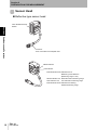
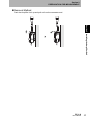
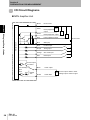
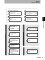
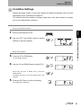
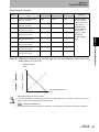
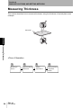
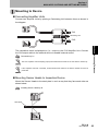
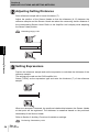
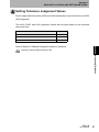
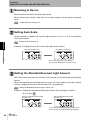
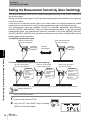
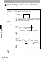
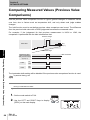
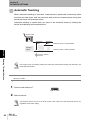
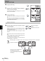
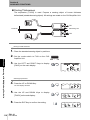
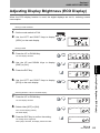
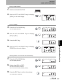
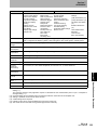
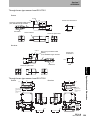
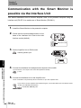
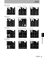
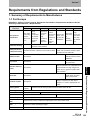
1
Smart Sensors Laser Type ZX-L-N Series User's Manual Cat. No. Z197-E1-03 Section 1 FEATURES Section 2 PREPARATION FOR MEASUREMENT Section 3 BASIC OPERATION Section 4 MAIN APPLICATIONS AND SETTING METHODS Section 5 DETAILED SETTINGS Section 6 AUXILIARY FUNCTIONS Section 7 APPENDIX User’s Manual Smart Sensors ZX-L-N Series ÇÕǹÇ?Ç Introduction Section ëÊ 1 èÕ1 Section ëÊ 2 èÕ2 Section ëÊ 3 èÕ3 Section ëÊ 4 èÕ4 Section 5 Section 6 Section 7 Introduction APPLICATION CONSIDERATIONS (Please Read) Introduction Introduction Introduction Introduction Thank you for purchasing the ZX-L-N Series Smart Sensor. This manual provides information regarding functions, performance and operating methods that are required for using the sensor. When using the ZX-L-N Smart Sensor, make sure to observe the following: • The ZX-L-N Smart Sensor must be operated by personnel knowledgeable in electrical engineering. • To ensure correct use, please read this manual thoroughly to deepen your understanding of the product. • Please keep this manual in a safe place so that it can be referred to whenever necessary. ii ZX-L-N User’s Manual Introduction Please read and understand this document before using the products. Please consult your OMRON representative if you have any questions or comments. WARRANTY OMRON’s exclusive warranty is that the products are free from defects in materials and workmanship for a period of one year (or other period if specified) from date of sale by OMRON. OMRON MAKES NO WARRANTY OR REPRESENTATION, EXPRESS OR IMPLIED, REGARDING NONINFRINGEMENT, MERCHANTABILITY, OR FITNESS FOR PARTICULAR PURPOSE OF THE PRODUCTS. ANY BUYER OR USER ACKNOWLEDGES THAT THE BUYER OR USER ALONE HAS DETERMINED THAT THE PRODUCTS WILL SUITABLY MEET THE REQUIREMENTS OF THEIR INTENDED USE. OMRON DISCLAIMS ALL OTHER WARRANTIES, EXPRESS OR IMPLIED. Introduction Introduction READ AND UNDERSTAND THIS DOCUMENT LIMITATIONS OF LIABILITY OMRON SHALL NOT BE RESPONSIBLE FOR SPECIAL, INDIRECT, OR CONSEQUENTIAL DAMAGES, LOSS OF PROFITS OR COMMERCIAL LOSS IN ANY WAY CONNECTED WITH THE PRODUCTS, WHETHER SUCH CLAIM IS BASED ON CONTRACT, WARRANTY, NEGLIGENCE, OR STRICT LIABILITY. In no event shall responsibility of OMRON for any act exceed the individual price of the product on which liability is asserted. IN NO EVENT SHALL OMRON BE RESPONSIBLE FOR WARRANTY, REPAIR, OR OTHER CLAIMS REGARDING THE PRODUCTS UNLESS OMRON’S ANALYSIS CONFIRMS THAT THE PRODUCTS WERE PROPERLY HANDLED, STORED, INSTALLED, AND MAINTAINED AND NOT SUBJECT TO CONTAMINATION, ABUSE, MISUSE, OR INAPPROPRIATE MODIFICATION OR REPAIR. SUITABILITY FOR USE THE PRODUCTS CONTAINED IN THIS DOCUMENT ARE NOT SAFETY RATED. THEY ARE NOT DESIGNED OR RATED FOR ENSURING SAFETY OF PERSONS, AND SHOULD NOT BE RELIED UPON AS A SAFETY COMPONENT OR PROTECTIVE DEVICE FOR SUCH PURPOSES. Please refer to separate catalogs for OMRON's safety rated products. OMRON shall not be responsible for conformity with any standards, codes, or regulations that apply to the combination of products in the customer’s application or use of the product. At the customer’s request, OMRON will provide applicable third party certification documents identifying ratings and limitations of use that apply to the products. This information by itself is not sufficient for a complete determination of the suitability of the products in combination with the end product, machine, system, or other application or use. The following are some examples of applications for which particular attention must be given. This is not intended to be an exhaustive list of all possible uses of the products, nor is it intended to imply that the uses listed may be suitable for the products: Outdoor use, uses involving potential chemical contamination or electrical interference, or conditions or uses not described in this document. Nuclear energy control systems, combustion systems, railroad systems, aviation systems, medical equipment, amusement machines, vehicles, safety equipment, and installations subject to separate industry or government regulations. Systems, machines, and equipment that could present a risk to life or property. Please know and observe all prohibitions of use applicable to the products. NEVER USE THE PRODUCTS FOR AN APPLICATION INVOLVING SERIOUS RISK TO LIFE OR PROPERTY WITHOUT ENSURING THAT THE SYSTEM AS A WHOLE HAS BEEN DESIGNED TO ADDRESS THE RISKS, AND THAT THE OMRON PRODUCT IS PROPERLY RATED AND INSTALLED FOR THE INTENDED USE WITHIN THE OVERALL EQUIPMENT OR SYSTEM. PERFORMANCE DATA Performance data given in this document is provided as a guide for the user in determining suitability and does not constitute a warranty. It may represent the result of OMRON’s test conditions, and the users must correlate it to actual application requirements. Actual performance is subject to the OMRON Warranty and Limitations of Liability. CHANGE IN SPECIFICATIONS Product specifications and accessories may be changed at any time based on improvements and other reasons. It is our practice to change model numbers when published ratings or features are changed, or when significant construction changes are made. However, some specifications of the product may be changed without any notice. When in doubt, special model numbers may be assigned to fix or establish key specifications for your application on ZX-L-N User’s Manual iii Introduction Introduction Introduction your request. Please consult with your OMRON representative at any time to confirm actual specifications of purchased products. DIMENSIONS AND WEIGHTS Dimensions and weights are nominal and are not to be used for manufacturing purposes, even when tolerances are shown. ERRORS AND OMISSIONS The information in this document has been carefully checked and is believed to be accurate; however, no responsibility is assumed for clerical, typographical, or proofreading errors, or omissions. PROGRAMMABLE PRODUCTS OMRON shall not be responsible for the user’s programming of a programmable product, or any consequence thereof. COPYRIGHT AND COPY PERMISSION This document shall not be copied for sales or promotions without permission. This document is protected by copyright and is intended solely for use in conjunction with the product. Please notify us before copying or reproducing this document in any manner, for any other purpose. If copying or transmitting this document to another, please copy or transmit it in its entirety. iv ZX-L-N User’s Manual Introduction The following signal words are used in this manual. Indicates a potentially hazardous situation which, if not avoided, will result in minor or moderate injury, or may result in serious injury or death. Additionally there may be significant property damage. Indicates a potentially hazardous situation which, if not avoided, may result in minor or moderate injury or in property damage. Introduction Meanings of Signal Words Meanings of Signal Words Meanings of Alert Symbols The following alert symbols are used in this manual. Indicates the possibility of laser radiation. Indicates prohibition when there is a risk of minor injury from electrical shock or other source if the product is disassembled. ZX-L-N User’s Manual v Introduction Introduction Laser Safety Laser Safety ZX-LD/ZX-LD30V Reflective Sensor Type Sensor Head Never look into the laser beam. Doing so continuously will result in visual impairment. Do not disassemble the product. Doing so may cause the laser beam to leak, resulting in the danger of visual impairment. ZX-LT Through-beam Type Sensor Head Do not look into the laser beam. Doing so continuously may result in visual impairment. vi ZX-L-N User’s Manual Introduction 2 Laser Products according to EN 60825-1 (IEC 60825-1) and Class II Laser Products according to FDA (21 CFR1040.10) (see note). The ZXLT Sensor Heads are Class 1 and Class II Laser Products, respectively. The ZX Series is meant to be built into final system equipment. Pay special attention to the following precautions for the safe use of the product: Note: Europe: Class 1 and Class 2 of EN 60825-1: 1994 +A11:1996 +A2:2001 Introduction Laser Safety The ZX-LD , ZX-LD L, ZX-LD V, and ZX-LD VL Sensor Heads are Class = IEC 60825-1:1993 +A1:1997 +A2:2001 U.S.A.: Class I and Class II of FDA (21 CFR1040.10) As for the Laser Product Classifications, refer to the Appendix, p.155 (1) ZX-LD/ZX-LD30V emits visual laser beam. Do not stare directly into the laser. Make sure that the laser beam path is terminated. If specular objects are present in the laser beam path, make sure that they are prevented from reflecting the laser beam. When used without an enclosure, make sure the laser path from eye level is avoided. (2) To avoid exposure to hazardous laser radiation, do not displace nor remove the protective housing during operation, maintenance, and any other servicing. (3) As for countries other than those of Europe and the U.S.A., observe the regulations and standards specified by each country. (4) Label Indications The EN and FDA labels are supplied with the product. Replace the current labels with them according to the instructions given in the manuals. ZX-L-N User’s Manual vii Introduction Introduction Precautions for Safe Use Precautions for Safe Use Please observe the following precautions for safe use of the products. Installation Environment • Do not use the product in environments where it can be exposed to inflammable/ explosive gas. • Do not install the product close to high-voltage devices and power devices in order to secure the safety of operation and maintenance. Power Supply and Wiring • The supply voltage must be within the rated range (DC12 to 24V±10%). • Reverse connection of power supply is not allowed. Connection to AC power supply is also not allowed. • Open-collector outputs should not be short-circuited. • High-voltage lines and power lines must be wired separately from this product. Wiring them together or placing in the same duct may cause induction, resulting in malfunction or damage. • Always turn off the power supply before connecting or disconnecting cables and connectors. Applicable standards • EN61326-1 • Electromagnetic environment: Industrial electromagnetic environment (EN/IEC 61326-1 Table 2) • There may be cases that current output or voltage output fluctuate within ±3 times of resolution when a sensor is experienced electromagnetic interference. Others • ZX-E series (linear proximity type), and ZX-W series (microwave type) and ZX-T series (high-precision contact type) must not be connected. Combined use of ZX-L with these series is not allowed. • Do not attempt to dismantle, repair, or modify the product. • Dispose of this product as industrial waste. viii ZX-L-N User’s Manual Introduction Please observe the following precautions to prevent failure to operate, malfunctions, or undesirable effects on product performance. Installation of the Product Installation Site Do not install the product in locations subjected to the following conditions: • Ambient temperature outside the rating • Rapid temperature fluctuations (causing condensation) • Relative humidity outside the range of 35 to 85% Introduction Precautions for Correct Use Precautions for Correct Use • Presence of corrosive or flammable gases • Presence of dust, salt, or iron particles • Direct vibration or shock • Reflective sensor of intense light (such as other laser beams or electric arc-welding machines) • Direct sunlight or near heaters • Water, oil, or chemical fumes or spray • Strong magnetic or electric field Component Installation and Handling Power Supply and Wiring • To extend the output cables of Amplifier Units, shielded cables of the same specifications as the output cables must be used. • When using a commercially available switching regulator, make sure that the FG terminal is grounded. • If surge currents are present in the power lines, connect surge absorbers that suit the operating environment. • When using two ore more amplifier units, make sure that the linear GND line of the amplifier units are connected to each other. • Before turning ON the power after the product is connected, make sure that the power supply voltage is correct, there are no incorrect connections (e.g. load shortcircuit) and the load current is appropriate. Incorrect wiring may result in breakdown of the product. • The cables must be 10m or shorter in total length, for both sensor head and amplifier units. To extend the cable from the sensor head, an optional extension cable (ZX-XC A) must be used. For extension of the cable of amplifier units, shielded cables of the same type must be used. • When using calculation units, make sure that the linear GND lines of the amplifier units are connected to each other. ZX-L-N User’s Manual ix Introduction Introduction Precautions for Correct Use Warming Up After turning ON the power supply, allow the product to stand for at least 10 minutes before use. The circuits are still unstable just after the power supply is turned ON, so measured values may fluctuate gradually. Maintenance and Inspection • Always turn OFF the power supply before adjusting or connecting/disconnecting the sensor head. • Do not use thinner, benzene, acetone or kerosene to clean the sensor head and amplifier units. If large dust particles adhere to the front filter of the sensor head, use a blower brush (used to clean camera lenses) to blow them off. Do not blow the dust away with your mouth. To remove smaller dust particles, use a soft cloth (for lenses) with a small amount of alcohol. Take care not to wipe them off with excessive force. Scratches on the filter may cause errors. Sensing Object For Reflective Type Sensor Head The product cannot accurately measure the following types of objects: Transparent objects, objects with an extremely low reflective sensor ratio, objects smaller than the spot diameter, objects with a large curvature, excessively inclined objects, etc. Mutual Interference Inserting a calculation unit between amplifier units can prevent mutual interference between two sensor heads. However, this may not work efficiently if one sensor head is saturated and a laser beam of the other sensor head is input. If you are interested in installing a calculation unit in order to prevent mutual interference, carry out a test using the actual system beforehand. x ZX-L-N User’s Manual Introduction Page Format z Title of each section z Header Section 6 AUXILIARY FUNCTIONS Indicates the contents of the page. Measuring with Multiple Amplifier Units Measuring with Multiple Amplifier Units z Overview This section describes the settings when Calculating Units are used to connect multiple Amplifier Units. Describes the overview and operation flow of the section. Performing Calculations z Cross-header z Overview and points of the function described Measurement results can be calculated between 2 Amplifier Units. The expression is set on the CH2 Amplifier Unit and the calculation results are also output from the CH2 Amplifier Unit. Calculations can also be performed between Sensors with different measuring ranges. The response time of the CH2 Amplifier Unit to which an expression is set will be prolonged by 1.0ms. Since the response time is influenced by the number of samples to average, the actual response time will be "response time based on the number of samples to average + 1.0ms" z Sub-header Setting the Number of Samples to Average p.66 z Purpose of operation Adding and Subtracting Measurement Results Moving to FUN and CALC Section 6 AUXILIARY FUNCTIONS 1. Set the mode switch to FUN on the CH2 Amplifier Unit. RUN T Introduction Editor's Note Editor's Note FUN 2. Use the LEFT and RIGHT Keys to display [CALC] on the main display. 3. Press the UP or DOWN Key. The sub-display will flash. Shows the contents of the operation to be performed. z Index label Shows the chapter number and contents. 4. Use the UP or DOWN Key to select the desired expression. 5. Press the ENT Key to confirm the setting. The setting will be registered. ZX- L Operation Manual 123 z Display Shows the display status resulting from the operation. z Keys or switches to be used Illustrates the keys and switches to be used. z Operation procedure and supplementary explanation Explains the operation procedure and the display status resulting from execution of the operation. Helpful information regarding operation and reference pages is introduced here using symbols. * This page does not exist. ZX-L-N User’s Manual xi Introduction Introduction Editor's Note Notational Conventions Menu In this manual, menu items displayed on the screen are enclosed with [ ]. Operation procedure Operation steps are numbered to indicate their order. Visual Aids Indicates points that are important to achieve the full product performance, such as operational precautions and application procedures. Indicates pages where related information can be found. Indicates information helpful in operation. xii ZX-L-N User’s Manual Introduction Introduction ii Precautions on Safety v Laser Safety vi Precautions for Safe Use viii Precautions for Correct Use ix Editor's Note xi Contents xiii Section 1 FEATURES 1 ZX-L Features 2 Section 2 PREPARATION FOR MEASUREMENT Introduction Contents Contents 9 Basic Configuration 10 Part Names and Functions 11 Installing the Amplifier Unit 16 Installing Sensor Heads 18 Connections 21 Wiring Input/Output Cables 27 ZX-L-N User’s Manual xiii Introduction Introduction Contents Section 3 BASIC OPERATION Flow of Operation 32 Basic Knowledge for Operation 34 Function Transition Charts 39 Setting the Auto Scale 42 Setting the Standard Received Light Amount 45 Measuring the Received Light Amount (Intensity Mode) 46 Section 4 MAIN APPLICATIONS AND SETTING METHODS 49 Measuring Height 50 Measuring Thickness 54 Measuring Eccentricity and Vibration 58 Measuring Edges 61 Section 5 DETAILED SETTINGS 65 Setting Number of Samples to Average 66 Changing Display Scales 67 Setting the Measurement Sensitivity (Gain Switching) 74 Using Hold Functions 76 Comparing Measured Values (Differentiation Function) 83 Comparing Measured Values (Previous Value Comparisons) 86 Entering Threshold Values 88 Linear Output 95 Setting Judgement Output Timing (Timer) xiv 31 ZX-L-N User’s Manual 104 Introduction 107 Measuring with Multiple Amplifier Units 108 Changing the Number of Display Digits 112 Reversing the Display 113 Adjusting Display Brightness (ECO Display) 115 Using the Zero Reset Function 116 Key Lock Function 122 Initializing Settings Data 123 Section 7 APPENDIX Introduction Contents Section 6 AUXILIARY FUNCTIONS 125 Troubleshooting 126 Error Messages and Countermeasures 127 Q&A 129 Glossary 130 Specifications and Dimensions 132 Communication with the Smart Monitor is possible via the Interface Unit 144 Engineering Data 146 Quick Reference for Displays 152 Requirements from Regulations and Standards 155 Index 164 Revision History 168 ZX-L-N User’s Manual xv Introduction Introduction Contents xvi MEMO ZX-L-N User’s Manual Section 1 Section 1 FEATURES FEATURES ZX-L Features 2 ZX-L-N User’s Manual 1 Section 1 FEATURES ZX-L Features The ZX-L Series provide the reflective type for displacement measurement and through-beam Section 1 ZX-L Features type for smart length measurement. Measurement is performed using laser. By irradiating laser beams to the object, the sensor can measure the distance between the object and sensor head, perform positioning and width judgement. Example: Measuring the height of a PCB mold Measuring method (Reflective Type) Sensing Distance object Measured value outputs Judgement outputs Example: Detecting cap floating Measuring method Sensing object (Throughbeam Type) Measured value outputs Judgement outputs 2 ZX-L-N User’s Manual Laser received or blocked amounts are measured at two points to detect whether the cap is floating or inclined by checking changes in the measured values. Section 1 FEATURES The Compact Body Provides Sufficient Space. The ZX-L series come in units as small as photoelectric sensors. This enables effective Many, Simple Functions Measurement Ready at Power ON The sensor can be used simply by installing and wiring it. Simply turn ON the power and it is ready to operate. The measurement results are displayed on the Amplifier Unit. Section 1 ZX-L Features use of limited installation space. LD ON Simple Calculation Settings Use a Calculating Unit to simply measure thickness and sum and difference calculations between two measurements. p.108 Thickness Calculating Unit ZX-L-N User’s Manual 3 Section 1 FEATURES Mutual Interference Prevention for Closely Mounted Sensor Heads Section 1 ZX-L Features The sensor has a mutual interference prevention function which allows multiple Sensor Heads to be mounted close to each other. This function is supported for up to two Sensor Heads by using ZX-CAL2 Calculating Units. p.24 Calculating Unit 4 ZX-L-N User’s Manual Section 1 FEATURES Compatibility between Sensor Heads and Amplifier Units maintenance or to switch to new products. Section 1 ZX-L Features Amplifier Units do not need to be changed when Sensor Heads are changed for Extendable Sensor Head Cables Special extension cables are provided to extend sensor heads. p.10 Special extension cable ZX-L-N User’s Manual 5 Section 1 FEATURES Monitoring Measurement Status Resolution Display for Sensing Object margins while viewing the resolution value. p.39 LD ON Resolution Section 1 ZX-L Features The resolution can be displayed, allowing judgements to be made about detection Deviation to be detected Resolution Confirm Measurement Status on a Personal Computer Use an Interface Unit and Smart Monitor to view measurement waveforms and log measurement data on a personal computer. This function is useful for making on-site measurement adjustments and for day-to-day quality control. p.15, p.144 Interface Unit Smart Monitor 6 ZX-L-N User’s Manual Amplifier Unit Section 1 FEATURES Useful Warning Functions Built-in Laser Life Monitor seconds on the Main Display when the power is turned ON. This assists in understanding when the Sensor Head should be replaced with a new one. LD ON ZERO ENABLE (mm) Section 1 ZX-L Features When the laser of Sensor Head deteriorates, [LDDWN] will appear for approx. five SUB ZX-L-N User’s Manual 7 Section 1 FEATURES MEMO Section 1 8 ZX-L-N User’s Manual Section 2 PREPARATION FOR MEASUREMENT Section 2 10 Part Names and Functions 11 Installing the Amplifier Unit 16 Installing Sensor Heads 18 Connections 21 Wiring Input/Output Cables 27 ZX-L-N User’s Manual PREPARATION FOR MEASUREMENT Basic Configuration 9 Section 2 PREPARATION FOR MEASUREMENT Basic Configuration The basic configuration of the ZX-L series Smart Sensors is shown below. ZX-L series Smart Sensors are not compatible with other ZX series Smart Sensors. ZX-L cannot be used with ZX-E, ZX-W and ZX-T series Smart Sensors. Section 2 Basic Configuration Smart Monitor (Software) ZX-SW11 Basic Configuration (Ver 3.0 or later) Enables operation of Amplifier Units from the personal computer and monitoring measured values. Personal Computer Sensor Head ZX-LD ZX-LT Detects the sensing object. p.18 Connecting Cable Commercially available cross cable Extension Cable ZX-XC1A(1m) ZX-XC4A(4m) ZX-XC8A(8m) ZX-XC9(9m) p.142 Interface Unit ZX-SF11 (Ver 2.0 or later) Used to connect to a personal computer or programmable controller. p.26 Amplifier Unit ZX-LDA11-N (NPN type) To be used between a Sensor Unit and Amplifier Unit. Only one extension cable can be used. ZX-XC9 can be used for ZX-LD only. ZX-LDA41-N (PNP type) Performs measurements and outputs measurement results. p.16 Calculating Unit ZX-CAL2 Used to connect two or more Amplifier Units. • Calculation • Mutual interference prevention p.24 Power Supply DC12 to 24V (±10%) 10 ZX-L-N User’s Manual Section 2 PREPARATION FOR MEASUREMENT Part Names and Functions Amplifier Unit Operating Section(*) Display Section(*) (3) Connector (two connectors, one on each side) (1) Input Cable (2) Current/voltage switch (on rear side) (*)Operating and Display (5) Laser indicator (6) Zero Reset indicator (7) ENABLE indicator Sections (8) HIGH indicator (15) Control Keys LD ON (9) PASS indicator (10) LOW indicator (11)Main Display (12) Sub-display (14) Mode switch Section 2 Part Names and Functions (4) Output Cable (13) Threshold switch (1) The input cable connects the Sensor Head. (2) The current/voltage switch selects either a current or voltage linear output. Current/voltage switch Voltage output Current output Monitor focus settings are also required when switching the output. p.95 (3) The connectors connect Calculation and Interface Units. (4) The output cable connects the sensor to the power supply and external devices, such as sync sensors or programmable controllers. (5) The Laser indicator lights while the Sensor Head is emitting a laser beam. (6) The Zero Reset indicator lights when the zero reset function is enabled. (7) The ENABLE indicator lights when the Sensor is ready for measurement. It goes off when measurement is not possible (e.g. when the received light amount is excessive or insufficient, when the measuring range is exceeded, or when the Sensor Head is not connected when the power is turned ON). (8) The HIGH indicator lights when the judgement result is HIGH. (9) The PASS indicator lights when the judgement result is PASS. (10) The LOW indicator lights when the judgement result is LOW. (11) The main display shows measured values and function names. (12) The sub-display shows additional information and function settings for measurements. Reading Displays p.35 (13) The threshold switch selects whether to set (and display) the HIGH or LOW threshold. (14) The mode switch selects the operating mode. Switching Modes p.34 (15) The Control Keys set measurement conditions and make other settings. Key Operations p.36 ZX-L-N User’s Manual 11 Section 2 PREPARATION FOR MEASUREMENT Sensor Head Reflective type sensor head Laser Emitter/Receiver Section Section 2 Part Names and Functions Connector To be connected to the Amplifier Unit. NEAR Indicator FAR Indicator Both NEAR and FAR indicators are lit: Measuring center distance (Measuring range x 10%) NEAR indicator is lit: Near side within measuring range FAR indicator is lit: Far side within measuring range Both NEAR and FAR indicators are blinking: Outside measuring range 12 ZX-L-N User’s Manual Section 2 PREPARATION FOR MEASUREMENT Through-beam Type Sensor Head Receiver (cable length: 0.5m) Receiving section Emitter (cable length: 0.5m) Section 2 Part Names and Functions Laser indicator Emitting section Lit while the laser is emitted. Connector Connector Sensor Head – Amplifier Unit Sensor Head – Amplifier Unit To be connected to the connecting cable. To be connected to the connecting cable. Connector Connector To be connected to the receiver. To be connected to the emitter. Cable: Black Cable: Gray Sensor Head – Amplifier Unit Connecting Cable (cable length: 1.5m) Side View Attachment Used to change the mount direction. Fixing screw Emitting section Fixing screw Receiving section Receiver Emitter ZX-L-N User’s Manual 13 Section 2 PREPARATION FOR MEASUREMENT Calculating Units Display (*) Connector (two connectors, one on each side) To be connected to the Amplifier Unit. Section 2 Part Names and Functions 14 * Display Detail Connection indicator Lit when the Amplifier Unit is connected. ZX-L-N User’s Manual Section 2 PREPARATION FOR MEASUREMENT Interface Units Display (*) Section 2 Part Names and Functions (2) Amplifier unit connector (1) Communications connector * Display Detail (3) Power supply indicator (4) Sensor communication indicator (BUSY/ERR) (5) External terminal communication indicator (BUSY/ERR) (1) The communications connector connects the communications cable to the computer. (2) The Amplifier Unit connector connects to the Amplifier Unit. (3) The power supply indicator lights while the power is supplied. (4) BUSY: Lights during communications with the Smart Sensor. ERR: Lights if an error occurs during communications with the Smart Sensor. (5) BUSY: Lights during communications with the personal computer. ERR: Lights if an error occurs during communications with the personal computer. ZX-L-N User’s Manual 15 Section 2 PREPARATION FOR MEASUREMENT Installing the Amplifier Unit Amplifier Units can be easily mounted to 35-mm DIN Track. Section 2 Installing the Amplifier Unit DIN Track (Option) PFP-100N (1m) PFP-50N (0.5m) PFP-100N2 (1m) End Plate (Option) PFP-M Installation Hook the connector end of the Amplifier Unit on the DIN Track and press in at the bottom until the Unit locks into place. Hook on the connector end Always hook the connector end of the Amplifier Unit on the DIN Track first. Mounting strength may decrease if the output cable end is hooked on the DIN Track first. 16 ZX-L-N User’s Manual Section 2 PREPARATION FOR MEASUREMENT Removal Method Push the Amplifier Unit up and pull out from the connector end. Section 2 Installing the Amplifier Unit ZX-L-N User’s Manual 17 Section 2 PREPARATION FOR MEASUREMENT Installing Sensor Heads This section describes how to install Sensor Heads. The installation method varies between the Reflective Type and Through-beam Type Sensor Heads. Installation Fix the Reflective type sensor head with screws. ZX-LD Mounting dimensional drawing (for M3 screws) (Unit: mm) 2-M3 26±0.1 32±0.1 Section 2 Installing Sensor Heads Reflective Type Sensor Head ZX-LD30V Mounting dimensional drawing (for M4 screws) (Unit: mm) 47±0.1 2-M4 When mounting a Sensor Head, take care not to touch the emitter and receiver. Adhesion of finger marks may hinder correct measurements. If you have touched them, wipe them with a clean, soft cloth. 18 ZX-L-N User’s Manual Section 2 PREPARATION FOR MEASUREMENT Through-beam Type Sensor Head Installation Fix the through-beam type sensor head with M3 screws. The screws must be tightened with a torque of 0.3N•m or lower. ZX-LT001/LT005 ZX-LT001/LT005 Mounting dimensional drawing (same for both 9±0.1 (Unit: mm) 2-M3 ZX-LT010 ZX-LT010 Mounting dimensional drawing (same for both emitter and 14±0.1 receiver) (Unit: mm) Section 2 Installing Sensor Heads emitter and receiver) 2-M3 Make sure that the emitter and receiver are mounted in the correct direction as shown below. Mounting them in the wrong direction will hinder correct measurements. Mounting hole Receiver Mounting hole Emitter ZX-L-N User’s Manual 19 Section 2 PREPARATION FOR MEASUREMENT Adjusting the Optical Axis Affix the optical axis adjustment seal (supplied with the sensor) on the front side of the receiver, and adjust the receiver position so that the laser beam is irradiated at the center of the cross on the seal. For more accurate adjustment, adjust the receiver position so that the Amplifier Unit shows the largest reading. Section 2 Installing Sensor Heads Optical axis adjustment seal • When adjusting the receiver position, take care not to touch the emitter and receiver of the sensor head. Adhesion of finger marks may hinder correct measurements. If you have touched them, wipe them with a clean, soft cloth. • The standard received light amount and scaling must be set after completion of optical axis adjustment. • After optical axis adjustment is complete, remove the optical axis adjustment seal. Setting the Standard Received Light Amount p.45, Scaling p.67 Installing the Side View Attachment Fix the side view attachment with M2 screws (supplied with the product). The screws must be tightened with a torque of 0.08N•m or lower. The side view attachment can be used even if only the emitter or receiver is mounted. Make sure that the emitter and receiver are mounted in the correct direction as shown below. Mounting them in the wrong direction will hinder correct measurements. Mounting hole Mounting hole • Make sure that the screws are tightened with the same torque. Tightening them with different torque may cause the optical axis to shift. • Tightening the screws with a torque exceeding 0.08N•m may damage the screw holes. Make sure that the screws are tightened with the specified torque. • After the side view attachment is mounted, adjust the optical axis. 20 ZX-L-N User’s Manual Section 2 PREPARATION FOR MEASUREMENT Connections This section describes how to connect component parts of the Smart Sensor. Before connecting/disconnecting Smart Sensor components, make sure that the power to the Amplifier Unit is turned OFF. The Smart Sensor may malfunction if components are connected or removed while the power is ON. Section 2 Connections Sensor Head Do not touch the terminals inside the connector. Connecting the Reflective Type Sensor Head Push the Sensor Head connector into the Amplifier Unit connector until it locks. Connecting the Through-beam Type Sensor Head 1. Push the emitter and receiver connectors into the connectors (×2) of the Sensor Head - Amplifier Unit connecting cable until they lock. Connect the emitter to the gray cable. Connect the receiver to the black cable. When connecting the Sensor Head, take care not to cause static electricity on the connectors. ZX-L-N User’s Manual 21 Section 2 PREPARATION FOR MEASUREMENT 2. Push the Sensor Head - Amplifier Unit cable connector into the Amplifier Unit connector until it locks. Section 2 Connections Disconnecting the Reflective Type Sensor Head To disconnect the Reflective Type Sensor Head, hold the Sensor Head's connector ring and the Amplifier Unit connector, and then pull them straight out. • Make sure to hold the connector of the Amplifier Unit to disconnect it. Failure to do so may damage the input cable of the Amplifier Unit. • Do not touch the terminals inside the connector. Connector Ring All settings on the Amplifier Unit will be cleared if the Sensor Head is replaced with a different type. Disconnecting the Through-beam Type Sensor Head 1. Hold the connector ring of the Sensor Head – Amplifier Unit connecting cable and the Amplifier Unit connector, and then pull them straight out. • Make sure to hold the connector of the Amplifier Unit to disconnect it. Failure to do so may damage the input cable of the Amplifier Unit. • Do not touch the terminals inside the connector. Connector Ring 22 ZX-L-N User’s Manual Section 2 PREPARATION FOR MEASUREMENT 2. Unhook the connector of the Sensor Head – Amplifier Unit cable from the emitter and receiver connectors, and pull them straight out as shown below. Section 2 Connections Hook ZX-L-N User’s Manual 23 Section 2 PREPARATION FOR MEASUREMENT Calculating Units When you want to perform calculations between Amplifier Units, prevent mutual interference between Sensor Heads or connect ZX-SF11 to perform communication between Amplifier Units, use a Calculating Unit to connect the Amplifier Units. The number of Amplifier Units that can be joined depends on the functions being used. Section 2 Connections Functions No. of Connectable Amplifier Units Calculation Max. 8 Mutual interference prevention Max. 2 Communication (when ZX-SF11 is used) Max. 5 Provide power to all connected Amplifier Units. Connection Method 2 3 4 1 1 1. Open the connector cover on the Amplifier Unit. Open the connector cover by lifting and sliding it open. 2. Mount the Calculating Unit to the DIN Track. 3. Slide and connect the Calculating Unit to the Amplifier Unit connector. 4. Slide and connect the second Amplifier Unit to the Calculating Unit connector. To disconnect the Interface Unit, perform the above operations in reverse order. 24 ZX-L-N User’s Manual Section 2 PREPARATION FOR MEASUREMENT Channel Numbers of Amplifier Units The following diagram shows the channel numbers when multiple Amplifier Units are connected. Section 2 Connections CH5 CH4 CH3 CH2 CH1 ZX-L-N User’s Manual 25 Section 2 PREPARATION FOR MEASUREMENT Interface Units Use an Interface Unit to connect a personal computer to the Smart Sensor system. Connection Method Section 2 Connections 2 3 1 1. Open the connector cover on the Amplifier Unit. Open the connector cover by lifting and sliding it open. 2. Mount the Interface Unit to the DIN Track. 3. Slide and connect the Interface Unit to the Amplifier Unit connector. To disconnect the Interface Unit, perform the above operations in reverse order. • When multiple Amplifier Units are used, connect the Interface Unit to the Amplifier Unit with the highest channel number. • Communication with the Smart Monitor is possible via the Interface Unit. p.144 26 ZX-L-N User’s Manual Section 2 PREPARATION FOR MEASUREMENT Wiring Input/Output Cables The input/output cable has the following wires. Wire the cable correctly. Incorrect wiring may damage the Smart Sensor. (1) A 12- to 24-VDC (±10%) power supply is connected to the power supply terminal. When using an Amplifier Unit with a PNP output, the power supply terminal is also the common I/O terminal for all I/O except for the linear output. Use a stabilized power supply separate from other devices and power systems for the Amplifier Unit, particularly when high resolution is required. Section 2 Wiring Input/Output Cables Brown (1) Power supply Blue (2) GND White (3) HIGH judgement output Green (4) PASS judgement output Gray (5) LOW judgement output Black (6) Linear output Shield (7) Linear GND Pink (8) LD-OFF input Orange (9) Zero reset input Purple (10) Timing input Red (11) Reset input (2) The GND terminal is the 0-V power supply terminal. When using an Amplifier Unit with an NPN output, the GND terminal is also the common I/O terminal for all I/O except for the linear output. (3) The HIGH judgement output outputs judgement results (HIGH). (4) The PASS judgement output outputs judgement results (PASS). (5) The LOW judgement output outputs judgement results (LOW). (6) The linear output outputs a current or voltage in accordance with the measured value. (7) The linear output GND terminal is the 0-V terminal for the linear output. • This ground wire must be grounded separately from the other ground wires. • Always ground the linear output terminal even when linear output is not used. (8) If this LD-OFF signal is ON, the laser will stop emission, causing a light amount error. In this case, the linear output, digital display, judgement output and judgement output display signals will be output according to the non-measurement settings. The sub-display will show [LDOFF]. (9) The zero reset input is used to execute and clear zero reset. p.118 (10) The timing input is for signal input from external devices. Use it for hold function timing. The sub-display will show [TIMIG] while the hold function timing is input. (11) The reset input resets all measurement processing and outputs. The sub-display will show [RESET] while the hold function reset is input. The linear and judgement output signals will be output according to the non-measurement settings. If this reset input switches ON while the hold function is used, the state in effect before the hold function was set will be restored. ZX-L-N User’s Manual 27 Section 2 PREPARATION FOR MEASUREMENT I/O Circuit Diagrams NPN Amplifier Unit Section 2 Wiring Input/Output Cables Brown DC12 to 24V White HIGH judgement Load Internal circuit output Load Green PASS judgement output Gray LOW judgement output Blue GND (0V) Pink LD-OFF input Purple Timing input Orange Zero reset input Red Reset input Load DC12 to 24V Current output 4 to 20mA Current/voltage Black Linear output output Switch 28 ZX-L-N User’s Manual 100Ω Voltage ±4V Shield Linear GND Load Current output: 300Ω or lower Voltage output: 10kΩ or higher Section 2 PREPARATION FOR MEASUREMENT PNP Amplifier Unit DC12 to 24V White HIGH judgement output Green PASS judgement output Gray LOW judgement output DC12 Load Section 2 Wiring Input/Output Cables Brown to 24V Load Internal circuit Load Blue GND (0V) Pink LD-OFF input Purple Timing input Orange Zero reset input Red Reset input Black Linear output Current output 4 to 20mA Current/voltage output Switch 100Ω Voltage ±4V Shield Linear GND Load Current output: 300Ω or lower Voltage output: 10kΩ or higher ZX-L-N User’s Manual 29 Section 2 PREPARATION FOR MEASUREMENT MEMO Section 2 30 ZX-L-N User’s Manual Section 3 BASIC OPERATION Basic Knowledge for Operation 34 Switching Modes 34 Reading Displays 35 Key Operations 36 Condition Settings 37 Inputting Numeric Values 38 Function Transition Charts 39 RUN Mode 39 T Mode 39 FUN mode 40 Setting the Auto Scale 42 Setting the Standard Received Light Amount 45 Measuring the Received Light Amount (Intensity Mode) 46 ZX-L-N User’s Manual BASIC OPERATION 32 Section 3 Flow of Operation 31 Section 3 BASIC OPERATION Flow of Operation Preparation for Measurement Installation and Connection Preparation for Measurement p.9 Turn ON the power. Section 3 Flow of Operation Preparation for Measurement When Through-beam Type Sensor Head is Connected When Reflective Type Sensor Head is Connected Installation and Connection Preparation for Measurement p.9 Turn ON the power. Select the display unit (% or mm) and the item to be measured (received or blocked light amount). Setting the Auto Scale p.42 (Not necessary if the two-point scaling function is used) Setting the Standard Received Light Amount Setting to Execution of Measurement Conditions p.45 Making Settings According to Your Application Measuring Height p.50 Measuring Thickness p.54 Measuring Eccentricity p.58 and Vibration p.61 Measuring Edges Setting/Changing Measurement Contents Setting Number of Samples to Average Using Hold Functions Comparing Measured Values (Differentiation Function) Comparing Measured Values (Previous Value Comparisons) Changing Display Scales Setting the Measurement Sensitivity (Gain Switching) p.66 p.76 p.83 p.86 p.67 p.74 Setting Judgement Conditions Entering Threshold Values p.88 Setting Output Contents Linear Output Setting Judgement Output Timing p.95 p.104 (If required) Correcting the Measurement Reference Point Using the Zero Reset Function p.116 32 ZX-L-N User’s Manual Section 3 BASIC OPERATION The Smart Sensor Does Not Operate Correctly Troubleshooting p.126 An Error Message Has Appeared Want to Know Meanings of Terms Glossary p.130 Want to Find Contents from Digital Displays Performing Calculations p.108 Quick Reference for Displays Additional Functions Measuring with Multiple Amplifier Units Error Messages and Countermeasures Saving Zero Reset Level (Zero Reset Memory) p.127 Section 3 Flow of Operation p.152 Using Power-Saving Mode p.115 Reversing the Display p.113 p.120 Key lock Function (For Zero Reset) p.122 Entering Display Offset Values p.117 Changing the Number of Display Digits p.112 (For Reflective Type Sensor Head) Displaying the Received Light Amount on the Main Display Intensity Mode p.46 Changing/Deleting Settings Applied Use of Functions When a Problem Occurs…. Initializing Settings Data p.123 ZX-L-N User’s Manual 33 Section 3 BASIC OPERATION Basic Knowledge for Operation Switching Modes The ZX-L has three modes. Use the Mode Switch on the Amplifier Unit to switch between modes. Switch to the desired mode before starting operation. Section 3 Basic Knowledge for Operation 34 LD ON RUN Mode Description RUN Normal operation mode T Mode for setting the threshold values FUN Mode for setting measurement conditions Function Transition Charts p.39 ZX-L-N User’s Manual T FUN Section 3 BASIC OPERATION Reading Displays The data displayed on the main and sub-displays depends on the mode currently selected. RUN mode has been selected prior to shipment from the factory. When the power is turned ON, the type of amplifier unit and then the number of channels will be displayed on the main display. The software version will be displayed on the sub-display. They are displayed for approx. three seconds, and then data for each mode will be displayed. Main Display Sub-display Mode RUN Main Display Sub-display Displays the measured value (the value Displays the threshold value, voltage, current, received after the measurement conditions have light amount, resolution and present value in order when been reflected). the Control Keys are pressed. For example, when the hold function is set, the held value will be displayed. Threshold Value Display Displays either the HIGH or LOW threshold value, depending on the position of the threshold switch. H T Displays the measured value (the value after the measurement conditions have been reflected). For example, when the hold function is set, the held value will be displayed. FUN Displays the function names in order when the Control Keys are pressed. Section 3 Basic Knowledge for Operation LD ON L Displays the threshold value for the threshold being set. Displays either the HIGH or LOW threshold value, depending on the position of the threshold switch. H L Displays the setting for the function displayed on the main display. Function Transition Charts p.39 ZX-L-N User’s Manual 35 Section 3 BASIC OPERATION Alphabet Display Format The alphabet appears on the main and sub-displays as shown in the following table. A B C D E F G H I J K L M N O P Q R S T U V W X Y Z Key Operations Section 3 Basic Knowledge for Operation Use the Control Keys to change the display and set measurement conditions. LD ON Control Keys The mode currently selected determines the key functions. Switching Modes p.34 Key LEFT Key Function RUN Mode T Mode Changes sub-display content. Used when selecting numeral digits. Function changes depending on setting. • Switches function display. • Selects numeral digit. • Stops setting. UP Key Performs timing input. Used when changing numerals. DOWN Key If the Sensor Head is the through-beam type, this cursor key is used to input reset signal. If the Sensor Head is the through-beam type, this cursor key is used to set the standard received light amount. Function changes depending on setting. • Switches between selections. • Changes numerals. Function changes depending on operation. • Confirms threshold value. • Executes teaching. Confirms the set condition or value. RIGHT Key Cursor Keys ENT Key 36 ZX-L-N User’s Manual FUN Mode When held down for one second: Performs zero reset. When held down together with the Right Key for three seconds: Cancels zero reset. Section 3 BASIC OPERATION Condition Settings Display the target function on the main display and select the desired value from the sub-display to set measurement conditions. This section uses the example of setting a peak hold as the hold condition to explain how to set measurement conditions. Moving to FUN mode and HOLD 2. Use the LEFT and RIGHT Keys to display LD ON [HOLD] on the main display. ZERO ENABLE (mm) Setting Hold Conditions 3. Press the UP or DOWN Key. The sub-display will flash. SUB Section 3 Basic Knowledge for Operation 1. Set the mode switch to FUN. 4. Use the UP and DOWN Keys to select [P-H]. SUB Press either the LEFT or RIGHT Key to cancel the selected option. The display will return to the current setting (OFF in this example). 5. Press the ENT Key to confirm the setting. The setting will be registered. SUB ZX-L-N User’s Manual 37 Section 3 BASIC OPERATION Inputting Numeric Values This section describes how to input numeric values for threshold and output settings. The example of direct input of the low threshold value will be used. Changing the low threshold from 40,000 to 39,000 Moving to T Mode Section 3 Basic Knowledge for Operation 1. Set the mode switch to T. RUN T FUN Setting Threshold Values 2. Set the switch to L. H L LD ON The measured value will be displayed on the main The current setting will be displayed on the sub-display. SUB 3. Press any Cursor Key. SUB will be enabled. 4. Use the UP and DOWN Keys to display 3. SUB 5. Use the LEFT or RIGHT Key to move the cursor to the one's digit. SUB 6. Use the UP and DOWN Keys to display 9. SUB To cancel the selected setting, use the LEFT Key to move the cursor to the leftmost digit and press the LEFT Key again. Alternatively, use the RIGHT Key to move to the rightmost digit and press the RIGHT Key again. The display will return to the current setting (40.000 in this example). 7. Press the ENT Key to confirm the setting. The display will change from flashing to being lit continuously and the numeric value will be registered. 38 ZX-L-N User’s Manual ENABLE (mm) display. The first digit on the sub-display will flash and direct input ZERO SUB Section 3 BASIC OPERATION Function Transition Charts Reading Transition Charts The upper section is the main display and the lower section is the sub-display. Main Display Sub-Display Measured value *1 (The main display always shows the measured value.) Threshold *1 Current Voltage Received light amount Resolution Present value *1 When the mode is switched to RUN, the measured and threshold values will be displayed first. The numerals shown in the above diagram are an example only. The actual display Section 3 Function Transition Charts RUN Mode may be different. p.130 What is the present value? T Mode There is no function transition in T mode. Measured value p.88 Threshold The numerals shown in the above diagram are an example only. The actual display may be different. In RUN and T modes, the position of the threshold switch will determine whether the HIGH or LOW threshold will be displayed. Threshold switch H HIGH L LOW ZX-L-N User’s Manual 39 Section 3 BASIC OPERATION FUN mode No. of samples to average Scaling *1 p.67 Hysteresis width Hold p.94 p.66 Trigger mode *1 When the mode is switched to FUN, scaling will be displayed first. Section 3 Function Transition Charts Auto scale *4 p.42 *4 p.78 Displayed only when the connected sensor head is the Through-beam type. p.76 If selected, will be displayed again without special functions displayed. If the connected sensor head is the Through-beam type, will be displayed. Special functions Previous value comparison *2 Differentiation function p.86 Linear output correction p.99 Intensity mode p.46 Monitor focus p.95 Differentiation cycle p.83 Display digit limit Eco mode Display reverse p.85 *2 Displayed if the hold function is not set to OFF. Zero reset p.116 Gain change p.74 p.112 Zero reset memory p.120 p.115 p.113 Non-measurement settings Clamp value setting p.102 All the special functions will be displayed if 40 ZX-L-N User’s Manual is selected. Section 3 BASIC OPERATION Timer Delay hold Timer time Delay time Sampling period p.81 Self-trigger level p.78 Special p.81 p.81 Self-trigger hysteresis width p.104 p.78 Initialization 2-sensor operation *3 p.123 Section 3 Function Transition Charts p.104 Thickness setting mode p.108 p.108 *3 Displayed on non-CH1 Amplifier Units if two or more Amplifier Units are connected. This symbol requests you to move to another menu using the LEFT or RIGHT Key after pressing the ENT Key to confirm the selections. ZX-L-N User’s Manual 41 Section 3 BASIC OPERATION Setting the Auto Scale This setting is required only when the Sensor Head is the Through-beam type. The auto scale function allows you to select whether the received light amount is to be displayed in mm or in % in the main display. It also allows you to select whether the received light amount or blocked light amount is to be displayed. When the auto scale is set, the maximum received (blocked) light amount to be displayed will be automatically scaled, and then it is displayed and output. If the two-point scaling function is used, auto scale setting is not necessary. Section 3 Setting the Auto Scale Two-point Scaling p.72 Selection Options Remarks Received light amount: L 100 - L L: d: Displays and outputs the received light amount. Displays and outputs the blocked light amount. 5: Sets the full scale to 5mm. 10: Sets the full scale to 10mm. 30: Sets the full scale to 30mm. Blocked light amount: d 5mm 10mm 30mm 100: Sets the full scale to 100%. 100% 42 ZX-L-N User’s Manual The full scale that is suitable for the sensor head's measuring width must be selected. Example: If ZXLT005 is used, [5-L] or [5-d] must be selected. - Section 3 BASIC OPERATION Display/Output Examples When light is 100% received When light is 50% received When light is 100% blocked 5-L Displays the received light amount in 0 to 5mm. 5.000 2.500 0.000 5-d Displays the blocked light amount in 0 to 5mm. 0.000 2.500 5.000 10-L Displays the received light amount in 0 to 10mm. 10.000 5.000 0.000 10-d Displays the blocked light amount in 0 to 10mm. 0.000 5.000 10.000 30-L Displays the received light amount in 0 to 30mm. 30.000 15.000 0.000 30-d Displays the blocked light amount in 0 to 30mm. 0.000 15.000 30.000 100-L Displays the received light amount in 0 to 100%. 100.00 50.00 0.00 100-d Displays the blocked light amount in 0 to 100%. 0.00 50.00 100.00 Remarks The linear output function is set so that the maximum output value is displayed for the maximum display value and the minimum output value for the minimum display value. Example: Relationship between the received light amount and displayed value when auto scale is set to [5-L] or [5-d]. Displayed value (mm) 0 5 Set to [5-d] Set to [5-L] 5 0 0 100 Section 3 Setting the Auto Scale Display Contents on Amplifier Unit Selection Received light amount (%) • The default setting at shipment is 100-L. • If you want to display the received light amount in a width other than “0 to 5mm”, “0 to 10mm” and “0 to 30mm”, the two-point scaling function must be used. Two-point Scaling p.72 • Auto scale must be set first. When auto scale is set, some settings (e.g. monitor focusing) are initialized. ZX-L-N User’s Manual 43 Section 3 BASIC OPERATION Moving to FUN Mode and AUTOS 1. Set the mode switch to FUN. 2. Use the LEFT and RIGHT Keys to display LD ON [AUTOS] on the main display. Section 3 Setting the Auto Scale 3. Press the UP or DOWN Key. 44 SUB 4. Select the desired auto scale. SUB 5. Press the ENT Key to confirm the setting. The selected auto scale will be set. ZX-L-N User’s Manual ENABLE (mm) Setting the Auto Scale The sub-display will flash. ZERO SUB Section 3 BASIC OPERATION Setting the Standard Received Light Amount This function can be used only when the Sensor Head is the Through-beam type. The current received light amount can be set as the standard received light amount. The standard received light amount must be set after installation of the sensor head and adjustment of optical axis. The amount of light input after the standard received light amount is set will be set to the full scale (F.S.). Example: When 85% is displayed for the received light amount after completion of optical axis adjustment Set the standard received light amount. The current light input amount will be set to the full scale, and the main display shows [100.00]. When the standard received light amount is set, [SETST] is displayed in the sub-display. • Setting of the standard received light amount must be carried out while zero reset is not in progress (i.e. while the zero reset indicator is not lit). • When the standard received light amount is set, the main display and linear outputs (current, voltage) will be set to the full scale (F.S.) automatically. • Setting of the standard received light amount can be done when the glass on the emitter/receiver gets dirty Section 3 Setting the Standard Received Light Amount [85.00] is displayed in the main display with the Amplifier Unit set to RUN mode. or when the received light amount has changed. • If the mount position of the sensor head is changed, the standard received light amount must be set again. Moving to RUN Mode 1. Set the mode switch to RUN. Setting the Standard Received Light Amount 2. Hold down the DOWN Key for more than three seconds. LD ON ZERO ENABLE (mm) The standard received light amount that has been set will be stored in the memory of the Amplifier Unit. ZX-L-N User’s Manual 45 Section 3 BASIC OPERATION Measuring the Received Light Amount (Intensity Mode) This function can be used only when the sensor head is the Reflective type. In the intensity mode, the received amount of light returning from the object can be displayed in the main display. The intensity mode can be used when you want to detect changes in the color or material of the object. In the intensity mode, distance measurement is not possible. • With the intensity mode, all processing, including 2-sensor operation, hold, threshold judgement and linear Section 3 Measuring the Received Light Amount (Intensity Mode) outputs, will be performed on the received light amount. • To use intensity mode, intensity mode must be set first. When intensity mode is set, some settings (e.g. monitor focusing) are initialized. • To use intensity mode, the measurement gain must be fixed to an option other than AUTO. Setting the Measurement Sensitivity (Gain Switching) p.74 Moving to FUN Mode and SPCL 1. Set the mode switch to FUN. 2. Use the LEFT and RIGHT Keys to display LD ON ZERO ENABLE [SPCL] on the main display. (mm) Moving to INTN 3. Press the UP or DOWN Key. The sub-display will flash. SUB 4. Use the UP and DOWN Keys to display [SET] or [ALL]. SUB 5. Press the ENT Key. SUB 6. Use the LEFT and RIGHT Keys to display [INTN] on the main display. 46 ZX-L-N User’s Manual LD ON ZERO ENABLE (mm) Section 3 BASIC OPERATION Switching to Intensity Mode 7. Press the UP or DOWN Key. The sub-display will flash. SUB 8. Use the UP and DOWN Keys to display [ON]. SUB The Sensor Head will be set to intensity mode. Section 3 Measuring the Received Light Amount (Intensity Mode) 9. Press the ENT Key to confirm the setting. SUB ZX-L-N User’s Manual 47 Section 3 BASIC OPERATION MEMO Section 3 48 ZX-L-N User’s Manual Section 4 MAIN APPLICATIONS AND SETTING METHODS Measuring Thickness 54 Measuring Eccentricity and Vibration 58 Measuring Edges 61 ZX-L-N User’s Manual MAIN APPLICATIONS AND SETTING METHODS 50 Section 4 Measuring Height 49 Section 4 MAIN APPLICATIONS AND SETTING METHODS Measuring Height This section describes how to measure the height of an object, using a PCB mold as an example. Mold PCB Section 4 Measuring Height Flow of Operation Place an actual sensing object in position. Have a reference sample ready beforehand. 1 50 2 Mounting to Adjusting Setting Device Position ZX-L-N User’s Manual 3 4 Setting Measuring Setting Tolerance Measurement Reference Judgement Timing Samples Values 5 Section 4 MAIN APPLICATIONS AND SETTING METHODS Mounting to Device Mount the Sensor Head to the inspection device. When mounting the sensor, take care not to exert pressure on the sensor head and wires. Installing Sensor Heads p.18 Adjusting Setting Position the Amplifier Unit's display or Sensor Head's indicators, and adjust the Sensor Head position so that the upper and lower limits of the height (H) to be measured fall within the measuring range. Measuring range p.130 Section 4 Measuring Height Place the reference sample in position and adjust the Sensor Head position. Refer to D Measured Value Display The Amplifier Unit display shows the distance (D) from the reference sample.(Default) The display can also be set to show the height (H) of the reference sample. Changing Display Scales p.67 H ZX-L-N User’s Manual 51 Section 4 MAIN APPLICATIONS AND SETTING METHODS Setting Measurement Timing Use the bottom hold function to hold the minimum value (bottom) during the sampling period. When the timing signal cannot be input from the device, set a self-down trigger. v Measured value Self-trigger level The bottom value is held. Section 4 Measuring Height t Sampling The following settings are required when the reference sample height is displayed using the scaling function: Measurement trigger: Self-up trigger Hold condition: Peak hold Refer to Section 5 Detailed Settings for details on settings. Using Hold Functions p.76 52 ZX-L-N User’s Manual Section 4 MAIN APPLICATIONS AND SETTING METHODS Measuring Reference Samples The height of the reference sample is measured using position teaching and the measurement result is registered as the HIGH threshold value. The registered value becomes the reference for the threshold value set in step . Section 4 Measuring Height Refer to Section 5 Detailed Settings for details on settings. Position Teaching p.90 The reference sample height can also be set to 0. Using the Zero Reset Function p.116 Setting Tolerance Judgement Values Refer to the HIGH threshold registered in step and set the upper and lower limits (HIGH and LOW thresholds) for a PASS (OK) judgement. The HIGH, PASS, and LOW judgement results will be output based on the threshold values set here. Measurement Result Judgement Measurement result > HIGH threshold HIGH LOW threshold ≤ Measurement result ≤ HIGH threshold PASS LOW threshold > Measurement result LOW Refer to Section 5 Detailed Settings for details on operation. Inputting Threshold Values Directly p.89 ZX-L-N User’s Manual 53 Section 4 MAIN APPLICATIONS AND SETTING METHODS Measuring Thickness This section describes how to measure thickness, using the thickness of a steel plate as an example. Steel plate Section 4 Measuring Thickness Flow of Operation 1 54 2 3 Mounting to Adjusting Setting Setting Device Distances Expressions ZX-L-N User’s Manual 4 Setting Tolerance Judgement Values Section 4 MAIN APPLICATIONS AND SETTING METHODS Mounting to Device Connecting Amplifier Units Connect two Amplifier Units by placing a Calculating Unit between them as shown in the diagram. CH1 Calculating Unit CH2 the CH2 output cable to the external device to enable external control. Connections p.21 The CH1 Amplifier Unit will display (output) the measurement result for the CH1 Sensor Head only. If the Amplifier Units are connected, mutual interference between the Sensor Heads can also be prevented. Section 4 Measuring Thickness The calculation result is displayed on (i.e., output to) the CH2 Amplifier Unit. Connect Mounting Sensor Heads to Inspection Device Mount the Sensor Heads to the steel plate in such a way that they face each other as shown below. Installing Sensor Heads p.18 Steel plate ZX-L-N User’s Manual 55 Section 4 MAIN APPLICATIONS AND SETTING METHODS Adjusting Setting Distances Set a reference sample with a known thickness (T). Adjust the position of the Sensor Heads so that the distances (A, B) between the reference sample and the Sensor Heads are about the measuring center distance of the corresponding Sensor Head. Refer to the Amplifier Unit's display while adjusting the Sensor Head position. Measuring range p.130 A Section 4 Measuring Thickness T B Setting Expressions Position the reference sample and set the expression to calculate the thickness of the reference sample. The settings are made on the CH2 Amplifier Unit. Select [THICK] as the expression type and enter the thickness (T) of the reference sample. T When the thickness is entered, the positional relationship between the Sensor Heads at that point will be registered. The thickness is measured based on the positional relationship of the Sensor Heads. Refer to Section 6 Auxiliary Functions for details on settings. Performing Calculations p.108 56 ZX-L-N User’s Manual Section 4 MAIN APPLICATIONS AND SETTING METHODS Setting Tolerance Judgement Values Set the upper and lower limits (HIGH and LOW thresholds) for the thickness for a PASS (OK) judgement. The HIGH, PASS, and LOW judgement results will be output based on the threshold values set here. Measurement Result Judgement Measurement result > HIGH threshold HIGH LOW threshold ≤ Measurement result ≤ HIGH threshold PASS LOW threshold > Measurement result LOW Section 4 Measuring Thickness Refer to Section 5 Detailed Settings for details on operation. Inputting Threshold Values Directly p.89 ZX-L-N User’s Manual 57 Section 4 MAIN APPLICATIONS AND SETTING METHODS Measuring Eccentricity and Vibration This section describes, as an example, how to measure the eccentricity of a motor shaft. Section 4 Measuring Eccentricity and Vibration 58 Motor shaft Flow of Operation 1 2 3 4 Mounting to Adjusting Setting Measuring Setting Tolerance Device Position Deflection ZX-L-N User’s Manual Judgement Values Section 4 MAIN APPLICATIONS AND SETTING METHODS Mounting to Device Mount the Sensor Head to the inspection device. When mounting the sensor, take care not to exert pressure on the sensor head and wires. Installing Sensor Heads p.18 Adjusting Setting Position Adjust the position of the Sensor Head so that the distance (D) between the Sensor diagram. Refer to the Amplifier Unit display while adjusting the Sensor Head position. Measuring range p.130 D ZX-L-N User’s Manual Section 4 Measuring Eccentricity and Vibration Head and the sensing object is about the measuring center distance, as shown in the 59 Section 4 MAIN APPLICATIONS AND SETTING METHODS Measuring Deflection Use the peak-to-peak hold function to measure the normal deflection. Rotate the motor shaft, input a timing signal from an external device, and measure the deflection. The difference between the maximum and minimum measurement results (the deflection) will be used as a reference when setting tolerances. v Measured value Deflection Section 4 Measuring Eccentricity and Vibration Timing input t Refer to Section 5 Detailed Settings for details on settings. Using Hold Functions p.76 Setting Tolerance Judgement Values Refer to the deflection measured in step and set either the upper limit (HIGH threshold) or lower limit (LOW threshold) for a PASS (OK) judgement. The judgement result will be output based on the threshold value set here. The output will depend on the type of threshold set. Output when upper limit is set: PASS or HIGH Output when lower limit is set: PASS or LOW Measurement Result Judgement Measurement result > HIGH threshold HIGH LOW threshold ≤ Measurement result ≤ HIGH threshold PASS LOW threshold > Measurement result LOW Refer to Section 5 Detailed Settings for details on operation. Inputting Threshold Values Directly p.89 60 ZX-L-N User’s Manual Section 4 MAIN APPLICATIONS AND SETTING METHODS Measuring Edges This section describes, as an example, how to measure the edges of a rubber sheet. Rubber sheet Section 4 Measuring Edges Flow of Operation 1 2 Mounting to Setting Auto Device Scale 4 5 Setting the Measuring Setting Tolerance Standard Received Reference Judgement Light Amount Samples Values 3 ZX-L-N User’s Manual 61 Section 4 MAIN APPLICATIONS AND SETTING METHODS Mounting to Device Mount the Sensor Head to the inspection device. When mounting the sensor, take care not to exert pressure on the sensor head and wires. Installing Sensor Heads p.18 Setting Auto Scale Decide whether to display the received light amount in mm or in % in the Amplifier Unit's main display. Section 4 Measuring Edges Setting the Auto Scale p.42 Example: To display 5mm as the current input light amount (85%) Before auto scale is set LD ON ZERO Auto scale is set to [5-L]. ENABLE LD ON ZERO ENABLE (mm) (mm) Since 100% is equivalent to 5.000mm, [4.250] will be displayed in the case of 85%. Setting the Standard Received Light Amount With 100% laser input from the emitter to the receiver, set the standard received light amount. When the standard received light amount is set, the main display and linear outputs (current, voltage) will be set to the full scale (F.S.) automatically. Setting the Standard Received Light Amount p.45 Example: Setting the standard received light amount after setting auto scale to [5-L] in step 2 Before the standard received light amount is set LD ON ZERO ENABLE After the standard received light amount is set LD ON (mm) ZERO ENABLE (mm) The current input light amount (85%) will be set to the full scale (F.S.) and [5.000] will be displayed. 62 ZX-L-N User’s Manual Section 4 MAIN APPLICATIONS AND SETTING METHODS Measuring Reference Samples The edge of the reference sample is measured using position teaching and the measurement result is registered as the HIGH threshold value. The registered value becomes the reference for the threshold value set in step . Section 4 Measuring Edges Refer to Section 5 Detailed Settings for details on settings. Position Teaching p.90 The reference sample edge can also be set to 0. Using the Zero Reset Function p.116 Setting Tolerance Judgement Values Refer to the HIGH threshold registered in step and set the upper and lower limits (HIGH and LOW thresholds) for a PASS (OK) judgement. The HIGH, PASS, and LOW judgement results will be output based on the threshold values set here. Measurement Result Judgement Measurement result > HIGH threshold HIGH LOW threshold ≤ Measurement result ≤ HIGH threshold PASS LOW threshold > Measurement result LOW Refer to Section 5 Detailed Settings for details on operation. Inputting Threshold Values Directly p.89 ZX-L-N User’s Manual 63 Section 4 MAIN APPLICATIONS AND SETTING METHODS MEMO Section 4 64 ZX-L-N User’s Manual Section 5 DETAILED SETTINGS Changing Display Scales 67 Setting the Measurement Sensitivity (Gain Switching) 74 Using Hold Functions 76 Comparing Measured Values (Differentiation Function) 83 Comparing Measured Values (Previous Value Comparisons) 86 Entering Threshold Values 88 Linear Output 95 Setting Judgement Output Timing (Timer) 104 ZX-L-N User’s Manual DETAILED SETTINGS 66 Section 5 Setting Number of Samples to Average 65 Section 5 DETAILED SETTINGS Setting Number of Samples to Average The average of the measured values obtained based on the preset number of samples can be output. This setting can be used when you want to ignore rapid changes in measured values. If this setting is made, response time for judgement and linear outputs will drop. In the case of Reflective Type Sensor Head, the Selection for No. of samples to average Response time 1 0.3 ms 256 prior to shipment from the factory. 2 0.5 ms In the case of Through-beam Type Sensor Head, 4 0.8 ms the number of samples to average has been set to 8 1.5 ms 32 prior to shipment from factory. 16 2.5 ms 32 5 ms 64 10 ms 128 20 ms 256 40 ms Section 5 Setting Number of Samples to Average 512 75 ms 1024 150 ms 2048 300 ms 4096 600 ms number of samples to average has been set to In general, when the number of samples to average is multiplied by “n”, the resolution will increase by Moving to FUN mode and AVE 1. Set the mode switch to FUN. 2. Use the LEFT and RIGHT Keys to display LD ON [AVE] on the main display. Selecting Number of Samples to Average The sub-display will flash. SUB 4. Use the UP and DOWN Keys to select the desired number of samples to average. SUB 5. Press the ENT Key to confirm the setting. The setting will be registered. ZX-L-N User’s Manual ZERO ENABLE (mm) 3. Press the UP or DOWN Key. 66 n . SUB Section 5 DETAILED SETTINGS Changing Display Scales Change the display scale when you want to display a value on the main display that is different from the actual measured value. Place an actual sensing object in position. Two setting methods are available: one-point and two-point scaling methods. • The scaling set here is reflected in the display only. If you want to change the linear output of the displayed value, the monitor focus function must be used. The minimum display value is -19999, and the maximum display value is 59999. Values (scaling correction values) that exceed the minimum or maximum display value even if the object is located within the measuring range cannot be set. An error will occur if such a value is set. p.95 • To calculate the thickness, refer to “Performing Calculations” in “Measuring with Multiple Amplifier Units”. p.108 Scaling Application Example Purpose Method Offset the display value. One-point scaling (Not inverted.) Displayed value (mm) Light block width 6mm Receiver Emitter p.69 15 Sensing object 6 Actual measured Height of sensing object 0 15mm To display the height of the sensing object (Reflective type sensor head) value 6 (mm) Offset the display value and invert the relationship between display and reference values. Displayed value Sensor head Sensing object One-point scaling (Inverted) p.69 (mm) Actual measured value 40mm Section 5 Changing Display Scales To display the height of the sensing object (Through-beam type sensor head) 50 40 Value to be Actual displayed measured 50mm value 40 (mm) ZX-L-N User’s Manual 67 Section 5 DETAILED SETTINGS Scaling Application Example Purpose Method To correct display values to match actual distances (Reflective type sensor head) Offset the display value and change the display value range. Two-point scaling p.72 Sensor head Displayed value (mm) 40 Actual distance: 40mm Displayed value: 38mm 38 Sensing object 33 32 Sensor head 32 Actual measured value (mm) 40 Section 5 Changing Display Scales Actual distance: 32mm Displayed value: 33mm Sensing object Two-point scaling To correct display values to match actual distances (Through-beam type sensor head) Emitter Receive Sensing object p.72 Displayed value (mm) 8 Actual distance: 2.5mm 7 Displayed value: 2mm Emitter Receiver 2.5 2 Sensing object Actual distance: 8mm Displayed value: 7mm 2.5 The settings listed below return to the default settings when scaling is set. Make the settings for these items after scaling settings have been completed. Self-trigger level, p.78 Monitor focus p.95 Zero Reset, p.116 Thickness setting (calculation) p.108 68 ZX-L-N User’s Manual 8 Actual measured value (mm) Section 5 DETAILED SETTINGS One-point Scaling Measurement is performed at one position and offset values are set for that measurement. The offset and increment/decrement inversion (display inversion) can be set. This section describes how to set one-point scaling, using an example of correcting display values to match actual distances. Example: Displaying the Height of the Sensing Object Displayed value Sensor head (mm) Actual measured value 40mm Sensing 40 Value to be displayed Actual measured 50mm value 40 (mm) Moving to FUN Mode and SCALE 1. Set the mode switch to FUN. 2. Use the LEFT and RIGHT Keys to display LD ON [SCALE] on the main display. ZERO ENABLE (mm) Section 5 Changing Display Scales object 50 Executing Scaling 3. Press the UP or DOWN Key. The sub-display will flash. SUB 4. Use the UP and DOWN Keys to display [ON]. SUB ZX-L-N User’s Manual 69 Section 5 DETAILED SETTINGS 5. Press the ENT Key to confirm the setting. LD ON ZERO ENABLE The sub-display will show [P1SCL]. 6. Set the sensing object at the position where (mm) SUB the display value change is required. Set the sensing object within the measurement distance. The ENABLE indicator will be lit when the sensing object is within the measurement distance. Scaling is not possible if the sensing object is not within the distance. 7. Press any Cursor Key. LD ON ZERO ENABLE The current measured value will be displayed on the (mm) main display. The leftmost digit of the sub-display will flash. SUB Section 5 Changing Display Scales 8. Use the Cursor Keys to set the offset for the Moves from one digit to measured value in the sub-display. another. The position of the decimal point can be changed using Changes the current value. the next steps. 9. Press the ENT Key to confirm the setting. The decimal point will flash. SUB 10. Use the LEFT and RIGHT Keys to change the position of the decimal point, if necessary. 11. Press the ENT Key to confirm the setting. The inverted display settings will appear on the subdisplay. 70 ZX-L-N User’s Manual SUB Section 5 DETAILED SETTINGS Selecting Inverted Display 12. Use the UP and DOWN Keys to select the inverted display function. Selection SUB Details D-FWD Not inverted. The larger the distance between the Sensor Head and the object, the larger the measured value displayed on the Amplifier Unit. D-INV Inverted The larger the distance between the Sensor Head and the object, the smaller the measured value displayed on the Amplifier Unit. 13. Press the ENT Key to confirm the setting. Section 5 Changing Display Scales The sub-display will be [P2SCL]. SUB 14. Press the ENT Key. Confirming that Scaling Is Completed If scaling has been completed correctly, the display will LD ON ZERO ENABLE be [OK]. (mm) SUB If scaling was unable to be completed, the display will be LD ON [NG]. ZERO ENABLE (mm) Check that the sensing object is within the measurement range and execute scaling again. SUB ZX-L-N User’s Manual 71 Section 5 DETAILED SETTINGS Two-point Scaling Measurement is performed at two positions and offset values are set for those measurements. Both an overall offset can be set and the range can be changed. This section describes how to set two-point scaling, using an example of correcting display values to match actual distances. Example: Correcting Display Values to Match Actual Distances Sensor head Displayed value (mm) 40 Actual distance: 40mm Displayed value: 38mm Sensing 38 33 32 object Section 5 Changing Display Scales 32 Actual measured value (mm) Sensor head Actual distance: 32mm Displayed value: 33mm Sensing object Separate the two specified points by at least 1% of the rated measurement range for the connected Sensor. For example, the rated measurement range for the ZX-LD40 Sensor is 20 mm. Therefore, the two specified points must be separated by 0.2 mm min. Setting the First Point 1. Set the first point by following steps 1. to 11. of the one-point scaling procedure. p.69 The range for two-point scaling is automatically set based on the values entered for the two points. Inverted display settings are ignored. 72 40 ZX-L-N User’s Manual Section 5 DETAILED SETTINGS Setting the Second Point 2. Place the sensing object in the position for which the display is to be changed (the second point). The sensing object must be set at a distance at least 1% of the rated measurement range away from the first point and also at a distance within the measurement range. 3. Press any Cursor Key. LD ON ZERO ENABLE The current measured value will be displayed on the (mm) main display. The leftmost digit of the sub-display will flash. SUB 4. Use the Cursor Keys to set the offset for the Moves from one digit to measured value. another. The position of the decimal point can be changed using Changes the current value. Section 5 Changing Display Scales the next steps. 5. Press the ENT Key to confirm the setting. The decimal point will flash. SUB 6. Use the LEFT and RIGHT Keys to move the decimal point. 7. Press the ENT Key to confirm the setting. Confirming the Completion of the Scaling Settings If scaling has been completed correctly, the display will LD ON ZERO ENABLE be [OK]. (mm) SUB If scaling was unable to be completed, the display will be LD ON [NG]. ZERO ENABLE (mm) Check the following points and then execute scaling again. • Is the sensing object within the measurement range? SUB • Are the two points separated by at least 1% of the rated measurement range? ZX-L-N User’s Manual 73 Section 5 DETAILED SETTINGS Setting the Measurement Sensitivity (Gain Switching) This section describes how to set the measurement gain according to the surface condition of the sensing object. Setting the measurement gain to AUTO will automatically adjust the sensitivity to the optimum level for the object. If the amount of reflective sensor light on the object does not change excessively, stable measurements can be carried out by fixing the measurement gain to an appropriate one. Five measurement gains are available: [AUTO] for automatic adjustment, and [BLACK], [WHITE], [METAL] and [MIROR], which are fixed measurement gains. In the case of fixed measurement gains, the measurement sensitivity increases in the order [MIROR], [METAL], [WHITE], [BLACK], [MIROR] with the lowest measurement sensitivity and [BLACK] with the highest measurement sensitivity. For [AUTO] measurement gain When the received light amount is not sufficient When the received light amount is excessive Large gain Switched Small gain automatically Section 5 Setting the Measurement Sensitivity (Gain Switching) For fixed measurement gains (other than [AUTO]) When the received light amount is not sufficient Insufficient received light amount (An error occurs, and the main display will show [E-DRK].) Within allowable received light amount range (Measurement possible) When the received light amount is excessive Saturated received light amount (An error occurs, and the main display will show [E-BRT].) AUTO can be set only when the Sensor Head is the Reflective type and the intensity mode is disabled. Intensity mode p.46 Moving to FUN Mode and SPCL 1. Set the mode switch to FUN. 2. Use the LEFT and RIGHT Keys to display [SPCL] on the main display. 74 When the received light amount is appropriate ZX-L-N User’s Manual LD ON ZERO ENABLE (mm) Section 5 DETAILED SETTINGS Moving to GAIN 3. Press the UP or DOWN Key. The sub-display will flash. 4. Use SUB the UP and DOWN Keys to display [ETC] or [ALL]. SUB 5. Press the ENT Key. SUB 6. Use the LEFT and RIGHT Keys to display LD ON [GAIN] on the main display. ZERO ENABLE (mm) Section 5 Setting the Measurement Sensitivity (Gain Switching) Setting the Measurement Gain 7. Press the UP or DOWN Key. The sub-display will flash. SUB 8. Select the desired measurement gain. SUB 9. Press the ENT Key to confirm the setting. The selected measurement gain will be set. SUB ZX-L-N User’s Manual 75 Section 5 DETAILED SETTINGS Using Hold Functions The hold functions hold data for specific points during the measurement period, such as the maximum or minimum value, and output those values at the end of the measurement period. Flow of Operation 2 1 Selecting Hold Setting the Trigger Condition for for Measurement in Measured Values Hold Mode 3 (If required) Setting Delay Time Selecting Hold Condition for Measured Values The time period from the start of hold measurements to the end of hold measurements Section 5 Using Hold Functions is called the sampling period. The value to be held during that sampling period is selected here. The CLAMP value is output until the first sampling period is finished. CLAMP value p.102 Any of the 5 settings shown in the table can be selected as the value to hold. Selection Details OFF (Default) Hold measurement is not performed. The measured value is always output. P-H (Peak hold) Holds the maximum value during the sampling period. The output changes at the end of the sampling period and is held until the end of the next sampling period. Current Maximum value Output measured value Sampling period B-H (Bottom hold) Holds the minimum value during the sampling period. The output changes at the end of the sampling period and is held until the end of the next sampling period. Current measured value Minimum value Sampling period 76 ZX-L-N User’s Manual Output Section 5 DETAILED SETTINGS Selection PP-H (Peak-to-peak hold) Details Holds the difference between the maximum and minimum values. This option is selected mainly when detecting vibration. The output changes at the end of the sampling period and is held until the end of the next sampling period. Maximum value Minimum value Current Output (maximum value - minimum value) Sampling period S-H (Sample hold) Holds the measured value at the start of the sampling period. The output changes at the start of the sampling period and is held until the start of the next sampling period. Output Current measured value Sampling period AVE-H (Average hold) Output (average of Current measured values) measured value Sampling period Moving to FUN mode and HOLD 1. Set the mode switch to FUN. 2. Use the LEFT and RIGHT Keys to display LD ON [HOLD] on the main display. ZERO Section 5 Using Hold Functions Holds the average measured value during the sampling period. The output changes at the end of the sampling period and is held until the end of the next sampling period. ENABLE (mm) Selecting Hold Condition 3. Press the UP or DOWN Key. The sub-display will flash. SUB 4. Use the UP and DOWN Keys to select the desired hold condition. SUB 5. Press the ENT Key to confirm the setting. The setting will be registered. SUB ZX-L-N User’s Manual 77 Section 5 DETAILED SETTINGS Setting the Trigger for Measurement in Hold Mode Select the input method for the timing of the start and end of the measurement period. Selection TIMIG (Timing input) Details Enter the trigger for the start of sampling by using the timing input. The period that the timing signal is ON is the sampling period. Timing input ON OFF Sampling period When a delay time is set, the input OFF timing and the end of the sampling period will not be synchronous. Sampling will end after the specified sampling period has expired. (Default) UP (Self-up trigger) The sampling period is the period that the measured value is greater than the specified self-trigger level. Hold measurement is possible without a sync input. Section 5 Using Hold Functions Self-trigger level Hysteresis width (For self-trigger) Measured value Sampling period Sampling period Operation point Return point When a delay time is set, the timing when the measured value becomes smaller than the self-trigger level and the end of the sampling period will not be synchronous. Sampling will end after the specified sampling period has expired. DOWN (Self-down trigger) The sampling period is the period that the measured value is lower than the specified self-trigger level. Hold measurement is possible without a sync input. Measured value Hysteresis width (For self-trigger) Self-trigger level Sampling period Operation point Return point When a delay time is set, the timing when the measured value becomes greater than the self-trigger level and the end of the sampling period will not be synchronous. Sampling will end after the specified sampling period has expired. • Set the hysteresis width based on the fluctuations in the measured values around the trigger level. The hysteresis will be applied from the start of the sampling period and will prevent timing input chattering. • Zero reset input will be invalid during sampling or while [-----] is displayed in the main display. • The timing input signal will be ignored if the self-trigger level is set to [UP] or [DOWN]. However, sampling will not be affected. 78 ZX-L-N User’s Manual Section 5 DETAILED SETTINGS Selecting Trigger Types 1. Use the LEFT and RIGHT Keys to display LD ON ZERO ENABLE [H-TRG] on the main display. (mm) [H-TRG] will not be displayed if the delay conditions are set to OFF. 2. Press the UP or DOWN Key. The sub-display will flash. SUB 3. Use the UP or DOWN Key to select the desired trigger type. SUB The selected trigger type will be registered. SUB Setting Trigger Levels (when UP or DOWN Is Selected) 5. Use the RIGHT or LEFT Key to display LD ON ZERO ENABLE [H-LVL] on the main display. (mm) [H-LVL] will not be displayed if timing input [TIMIG] is set Section 5 Using Hold Functions 4. Press the ENT Key to confirm the setting. as the trigger. 6. Press the UP or DOWN Key. The leftmost digit of the sub-display will flash. 7. Use the Cursor Keys to set the desired trigger level. SUB Moves from one digit to another. Changes the current value. 8. Press the ENT Key to confirm the setting. The trigger level will be registered. SUB ZX-L-N User’s Manual 79 Section 5 DETAILED SETTINGS Setting Hysteresis Width (when UP or DOWN Is Selected) 9. Use the LEFT and RIGHT Keys to display LD ON ZERO ENABLE [H-HYS] on the main display. (mm) [H-HYS] will not be displayed if timing input [TIMIG] is set as the trigger. 10. Press the UP or DOWN Key. The leftmost digit of the sub-display will flash. 11. Use the Cursor Keys to set the hysteresis width for the trigger level. SUB Moves from one digit to another. Changes the current value. 12. Press the ENT Key to confirm the setting. The hysteresis width will be registered. Section 5 Using Hold Functions 80 ZX-L-N User’s Manual SUB Section 5 DETAILED SETTINGS Setting Delay Time Delay time is set to ignore measurements immediately after the timing input. This is useful for avoiding bounding during device startup and the influence of machine vibration. The delay time (the delay between timing input and the start of sampling) and the sampling period can be set. The default delay time setting is [OFF]. Make the sum of the delay time and sampling period less than the timing input ON interval. If the next timing input for measurement is received before the delay and sampling period have passed, that timing input will be ignored and will not be reflected in the sampling. Delay time Sampling period Delay time ON Timing input OFF Accepted Moving to Delay Hold (H-DLY) 1. Use the LEFT and RIGHT Keys to display LD ON [H-DLY] on the main display. ZERO ENABLE (mm) Section 5 Using Hold Functions Ignored [H-DLY] will not be displayed if the delay conditions are set to [OFF]. 2. Press the UP or DOWN Key. The sub-display will flash. SUB 3. Use the UP and DOWN Keys to display [ON]. SUB 4. Press the ENT Key. The settings mode for the H-DLY function is now SUB enabled. ZX-L-N User’s Manual 81 Section 5 DETAILED SETTINGS Setting Delay Time 5. Use the LEFT and RIGHT Keys to display LD ON ZERO ENABLE [H-D-T] on the main display. (mm) [H-D-T] will not be displayed if the H-DLY function is set to [OFF]. 6. Press the UP or DOWN Key. The leftmost digit of the sub-display will flash. 7. Enter the delay time (ms). SUB Moves from one digit to another. Changes the current value. Section 5 Using Hold Functions 8. Press the ENT Key to confirm the setting. The delay time will be registered. SUB Setting the Sampling Period 9. Use the LEFT and RIGHT Keys to display LD ON ZERO ENABLE [H-S-T] on the main display. (mm) [H-S-T] will not be displayed if the H-DLY function is set to [OFF]. 10. Press the UP or DOWN Key. The leftmost digit of the sub-display will flash. 11. Use the Cursor Keys to enter the sampling period (ms). SUB Moves from one digit to another. Changes the current value. 12. Press the ENT Key to confirm the setting. The sampling period will be registered. 82 ZX-L-N User’s Manual Section 5 DETAILED SETTINGS Comparing Measured Values (Differentiation Function) Use the differentiation function to detect only sudden changes in the measured values that occur during very short periods of time. The differentiation function detects changes between the present value and the measured value that is in effect just before the comparing pitch. The coefficient of this comparing pitch is defined as the differentiation cycle. The relationship between the differentiation cycle and comparing pitch can be calculated by the following equation. Comparing pitch = Differentiation cycle x 150µs Example: When differentiation cycle = 10 Present value Section 5 Comparing Measured Values (Differentiation Function) Sampling Sampling time (150µs) Comparing pitch 1.5ms (150µs x 10) Displayed value (Differentiation result) If you want to detect changes in hold value, use the previous value comparison function. Previous value comparison p.86 Moving to FUN Mode and SPCL 1. Set the mode switch to FUN. 2. Use the LEFT and RIGHT Keys to display [SPCL] on the main display. LD ON ZERO ENABLE (mm) ZX-L-N User’s Manual 83 Section 5 DETAILED SETTINGS Moving to DIFF 3. Press the UP or DOWN Key. The sub-display will flash. SUB 4. Use the UP and DOWN Keys to display [SET] or [ALL]. SUB 5. Press the ENT Key. SUB 6. Use the LEFT and RIGHT Keys to display Section 5 Comparing Measured Values (Differentiation Function) 84 LD ON [DIFF] on the main display. 7. Press the UP or DOWN Key. SUB 8. Use the UP and DOWN Keys to display [ON]. SUB 9. Press the ENT Key to confirm the setting. Settings for differentiation cycle can now be made. ZX-L-N User’s Manual ENABLE (mm) Moving to Differentiation Cycle The sub-display will flash. ZERO SUB Section 5 DETAILED SETTINGS Setting the Differentiation Cycle 10. Use the LEFT and RIGHT Keys to display LD ON ZERO ENABLE [D-CYC] on the main display. (mm) [D-CYC] will not be displayed if the DIFF is set to OFF. 11. Press the UP or DOWN Key. The leftmost digit of the sub-display will flash. 12. Use the Cursor Keys to set the differentiation cycle. SUB Moves from one digit to another. Changes the current value. The setting will be registered. Section 5 Comparing Measured Values (Differentiation Function) 13. Press the ENT Key to confirm the setting. SUB ZX-L-N User’s Manual 85 Section 5 DETAILED SETTINGS Comparing Measured Values (Previous Value Comparisons) Use the previous value comparison function to ignore gradual changes in measured values over time, due to factors such as temperature drift, and only detect and judge sudden changes. The hold function must be set before previous value comparison can be set. The difference from the previous hold value with a PASS judgement becomes the measured value. For example, if the judgement for that previous measurement is HIGH or LOW, the comparison is performed with the hold value before that. Sudden change X(n) X(n-1) Hold value Section 5 Comparing Measured Values (Previous Value Comparisons) 86 Gradual change Measured value (After comparison with previous value) X(n)-X(n-1) PASS ON OFF HIGH ON OFF HIGH threshold The hysteresis width setting will be disabled if the previous value comparison function is used. Hysteresis Setting p.94 Moving to FUN Mode and SPCL 1. Set the mode switch to FUN. 2. Use the LEFT and RIGHT Keys to display [SPCL] on the main display. ZX-L-N User’s Manual LD ON ZERO ENABLE (mm) Section 5 DETAILED SETTINGS Moving to COMP 3. Press the UP or DOWN Key. The sub-display will flash. SUB 4. Use the UP and DOWN Keys to display [SET] or [ALL]. SUB 5. Press the ENT Key. SUB 6. Use the LEFT and RIGHT Keys to display LD ON [COMP] on the main display. ZERO ENABLE (mm) Section 5 Comparing Measured Values (Previous Value Comparisons) Setting Previous Value Comparison 7. Press the UP or DOWN Key. The sub-display will flash. SUB 8. Use the UP and DOWN Keys to display [ON]. SUB 9. Press the ENT Key to confirm the setting. The previous value comparison function can now be SUB used. ZX-L-N User’s Manual 87 Section 5 DETAILED SETTINGS Entering Threshold Values Threshold values are set to determine the range for PASS judgements. Both HIGH and LOW threshold values are set. There are three judgement outputs: HIGH, PASS and LOW. HIGH threshold Measured value LOW threshold Output HIGH ON OFF PASS ON OFF LOW ON OFF (ON when Measurement result > HIGH threshold ) (ON when LOW threshold ≤ Measurement result ≤ HIGH threshold) (ON when Measurement result < LOW threshold ) Section 5 Entering Threshold Values The following table outlines the three methods for setting the threshold values. Method Details Direct input The threshold values can be set by directly inputting the numeric values. Direct input is useful when you know the dimensions for an OK judgement or when you want to fine-tune threshold values after teaching. Position teaching Performs measurement and uses the measurement results to set threshold values. Position teaching is useful when threshold samples, i.e., with the upper and lower limits, can be obtained beforehand. Two-point teaching Sets the intermediate point between the first and second teaching points as the threshold value. Two-point teaching is useful to detect small surface steps on the sensing object. Automatic teaching Performs measurement continuously while the keys are held down and sets the maximum and minimum measurements during that period as the threshold values. Automatic teaching is useful when you want to set threshold values by starting the device and obtaining real measurements. Hysteresis (hysteresis width) can also be set for threshold values. Set hysteresis when judgements are unstable to prevent chattering. p.94 88 ZX-L-N User’s Manual Section 5 DETAILED SETTINGS Inputting Threshold Values Directly The threshold values can be set by directly inputting the numeric values. Direct input is useful when you know the dimensions for an OK judgement or when you want to fine-tune threshold values after teaching. Moving to T Mode 1. Set the mode switch to T. RUN T FUN Setting Threshold Values 2. Move the threshold switch to either H or L, H L LD ON ZERO ENABLE i.e., the threshold to be set. (mm) The current measured value will be displayed on the main display. SUB depending on the threshold switch setting) will be displayed on the sub-display. 3. Press any Cursor Key. The leftmost digit of the sub-display will flash. 4. Use the Cursor Keys to set the threshold value. SUB Moves from one digit to another. Changes the current value. 5. Press the ENT Key to confirm the setting. The setting will be registered. SUB Section 5 Entering Threshold Values The currently set threshold value (either HIGH or LOW, Countermeasures for Setting Errors If ERRLH or ERRHL is displayed, the following error has occurred. SUB • HIGH threshold value < LOW threshold value • HIGH threshold value - LOW threshold value < hysteresis width SUB Hysteresis Setting p.94 If an error is displayed, the threshold values have not been updated. Set the threshold values again. ZX-L-N User’s Manual 89 Section 5 DETAILED SETTINGS Position Teaching Performs measurement and uses the measurement results to set threshold values. Position teaching is useful when threshold samples, i.e., with the upper and lower limits, can be obtained beforehand. Sensor head Sensor head Teaching point = LOW threshold Threshold sample (Upper limit) Teaching point = HIGH threshold Threshold sample (Lower limit) Hold, trigger mode, and scaling settings that have been made before teaching are reflected in the teaching measurements. Section 5 Entering Threshold Values Moving to T Mode 1. Set the mode switch to T. RUN T FUN Setting Threshold Values 2. Move the threshold switch to either H or L, LD ON i.e., the threshold to be set. The current measured value will be displayed on the main display. The currently set threshold value (either HIGH or LOW, depending on the threshold switch setting) will be displayed on the sub-display. ZERO ENABLE (mm) SUB 3. Place the threshold sample in position. The main display value changes. 4. Press the ENT Key for at least one second and then release. SUB The measured value at the point that the ENT Key is released will be set as the threshold value. This threshold value will be shown on the sub-display. When [ERRLH] or [ERRHL] is displayed p.89 The threshold values set using position teaching can be changed using direct input. This is useful when setting judgement tolerances for measured values. p.89 90 ZX-L-N User’s Manual Section 5 DETAILED SETTINGS Two-point teaching Performs measurement on two samples and uses the intermediate value of the two measurement results to set threshold values. Two-point teaching is useful when you want to detect subtle differences between the standard sample and defective samples. Sensor head Sensor head Teaching point A Standard sample Teaching point B Defective sample The threshold can be calculated by the following equation. Threshold = (Teaching point A + Teaching point B) / 2 teaching measurements. Setting Teaching point A 1. Set the teaching point A by following steps 1. to 4. of the position teaching procedure. SUB Setting Threshold Values 2. Place a defective sample in position. Section 5 Entering Threshold Values Hold, trigger mode, and scaling settings that have been made before teaching are reflected in the The main display value changes. 3. Press the ENT Key for at least three seconds and then release. SUB The measured value at the point that the ENT Key is released will be set as the value for teaching point B to set threshold value. This threshold value will be shown on the sub-display. When [ERRLH] or [ERRHL] is displayedp.89 The threshold values set using two-point teaching can be changed using direct input. This is useful when setting judgement tolerances for measured values. p.89 ZX-L-N User’s Manual 91 Section 5 DETAILED SETTINGS Automatic Teaching When automatic teaching is executed, measurement is performed continuously while the keys are held down, and the maximum and minimum measurements during that period are set as the threshold values. Automatic teaching is useful when you want to set threshold values by starting the device and obtaining real measurements. Sensor head Maximum value Minimum value Minimum value = LOW threshold Sensing object Section 5 Entering Threshold Values Maximum value = HIGH threshold Moved Hold, trigger mode, and scaling settings that have been made before teaching are reflected in the teaching measurements. Moving to T Mode 1. Set the mode switch to T. RUN T FUN 2. Start the device. The threshold switch can be set to either position. Both HIGH and LOW thresholds will be set, regardless of the switch setting. 92 ZX-L-N User’s Manual Section 5 DETAILED SETTINGS Setting Threshold Values 3. Start measurement. Measurement will continue while the ENT and RIGHT LD ON Keys are held down. ZERO ENABLE (mm) [AUTOT] will flash on the sub-display. SUB 4. Release the ENT and RIGHT Keys to end measurement. The maximum measured value during the measurement period will be set as the HIGH threshold value and the minimum will be set as the LOW threshold value. depending on the threshold switch setting) will be SUB displayed on the sub-display. When ERRLH is displayed p.89 The threshold values set using automatic teaching can be changed using direct input. This is useful when setting judgement tolerances for measured values. p.89 ZX-L-N User’s Manual Section 5 Entering Threshold Values The new threshold value (either HIGH or LOW, 93 Section 5 DETAILED SETTINGS Hysteresis Setting Set the hysteresis width for the upper and lower limits of judgements if the HIGH, PASS, or LOW judgement is unstable near the threshold values. HIGH threshold Hysteresis (hysteresis width) Measured value Operation point Return point LOW threshold Output HIGH ON OFF PASS ON OFF LOW ON OFF Hysteresis width settings are disabled when previous value comparison is used. p.86 Section 5 Entering Threshold Values To prevent self-trigger chattering, set hysteresis for the self-trigger. p.78 Moving to FUN Mode and HYS 1. Set the mode switch to FUN. 2. Use the LEFT and RIGHT Keys to display LD ON ZERO ENABLE [HYS] on the main display. (mm) 3. Press the UP or DOWN Key. The leftmost digit of the sub-display will flash. 4. Use the Cursor Keys to enter the hysteresis width. SUB Moves from one digit to another. Changes the current value. 5. Press the ENT Key to confirm the setting. The setting will be registered. SUB Countermeasures for Setting Errors If [ERROV] is displayed, [HIGH threshold – LOW threshold] is smaller than the hysteresis width. If an error is displayed, the threshold values have not been updated. Set the values again or change the threshold values. 94 ZX-L-N User’s Manual SUB Section 5 DETAILED SETTINGS Linear Output Output Settings (Monitor Focus) Linear output refers to the conversion of measurement results to a 3 to 21mA current output or a -5 to 5V voltage output. The relationship between displayed measured values and output values can be set freely. Match the settings to suit the connected external device. Enter the output values for any two current values or voltage values to set the output range. Example: Setting 35mm to 4mA Output and 45mm to 20mA Output (for Current Output) Output current (mA) (mA) 20 20 4 4 0 20 Measured value (mm) 0 Measured 35 45 Section 5 Linear Output Output current value (mm) Separate the two specified points by at least 1% of the rated measurement range for the connected Sensor. For example, the rated measurement range for the ZX-LD40 Sensor is 20mm. Therefore, the two specified points must be separated by 0.2mm min. Using the Zero Reset Function Zero reset is released when monitor focus is set. Execute the zero reset again after setting monitor focus. Zero Reset, p.116 ZX-L-N User’s Manual 95 Section 5 DETAILED SETTINGS This section describes how to set the output range, using an example of current output with a range with the following conversions: 35mm to 4 mA and 45mm to 20 mA. Change the values in this example for voltage output as necessary. Output current Output current (mA) (mA) 20 20 4 4 Measured value 0 20 (mm) 0 Measured value 35 (mm) 45 1. Turn OFF the power supply to the Amplifier Unit. Section 5 Linear Output 2. Move the current/voltage switch to current output. The switch is found on the bottom of the Amplifier Unit. The default setting is voltage output. Voltage output Current output Moving to FUN Mode and SPCL 3. Turn ON the power supply and move the mode switch to FUN. 4. Use the LEFT and RIGHT Keys to display LD ON [SPCL] on the main display. SUB The sub-display will flash. 6. Use the UP and DOWN Keys to display [SET] or [ALL]. SUB 7. Press the ENT Key. SUB 96 ZX-L-N User’s Manual ENABLE (mm) Moving to FOCUS 5. Press the UP or DOWN Key. ZERO Section 5 DETAILED SETTINGS 8. Use the LEFT and RIGHT Keys to display LD ON ZERO ENABLE FOCUS on the main display. (mm) Selecting Current (mA) or Voltage (V) Output 9. Press the UP or DOWN Key. SUB The sub-display will flash. 10. Display [mA]. Always select the same output as the current/voltage switch selection on the bottom of the Amplifier Unit. Setting the First Point (A) LD ON ZERO ENABLE The display will change to the settings for the first point (mm) (A). The output current will be displayed on the main display. The measured value will be displayed on the sub-display SUB and the leftmost digit will flash. 12. Set the output current value and the Moves from one digit to corresponding measured value for the first another. point. Changes the current value. Section 5 Linear Output 11. Press the ENT Key. Set a measured value within the measurement distance. If scaling or calculation has been set, set a value that reflects those settings. The flashing digit, i.e., the digit for which a value can be set, will change as shown in the diagram. LD ON ZERO ENABLE LD ON (mm) ZERO ENABLE (mm) Shifts one digit at a time. Digit shift on sub-display SUB SUB Switching from the sub-display to the LD ON ZERO ENABLE (mm) main display and vice versa (From the leftmost/rightmost digit of the sub-display) SUB ZX-L-N User’s Manual 97 Section 5 DETAILED SETTINGS 13. Press the ENT Key to confirm the setting. LD ON ZERO ENABLE The setting for the first point will be confirmed. (mm) The screen for setting the second point correction value will be displayed. SUB Setting the Second Point (B) 14. Use the same procedure as for the first point to set the output current value LD ON ZERO ENABLE and (mm) corresponding measurement result for the second point. SUB Section 5 Linear Output 15. Press the ENT Key to confirm the setting. LD ON ZERO ENABLE (mm) SUB Confirming Completion of Monitor Focus Settings The display will read [OK] if monitor focus has been set LD ON ZERO ENABLE correctly. (mm) SUB If not, the display will show [NG]. LD ON ZERO ENABLE (mm) If [NG] is displayed, check the following points and execute the monitor focus again. • Is the measured value set on the sub-display within the measurement distance (with scaling and calculation settings reflected if set)? • Are the first and second points separated by at least 1% of the rated measurement distance? • Are the current (or voltage) values for the two points the same? 98 ZX-L-N User’s Manual SUB Section 5 DETAILED SETTINGS Correcting Linear Output Values Discrepancies may occur between the linear output current (or voltage) values set on the Amplifier Unit and the actual current (or voltage) values measured due to the conditions for the connected external device or other factors. The linear output correction function can be used to correct this discrepancy. The output values are corrected by entering the correction value for the current or voltage values for any two points. Set the monitor focus function and select either current or voltage output beforehand. p.95 This section uses a current output as an example. Change the values in this example for voltage output as necessary. Section 5 Linear Output 1. Connect the linear output to an external ammeter. Moving to FUN Mode and SPCL 2. Turn ON the power supply and move the mode switch to FUN. 3. Use the LEFT and RIGHT Keys to display LD ON [SPCL] on the main display. ZERO ENABLE (mm) Moving to LEFT-ADJ 4. Press the UP or DOWN Key. The sub-display will flash. SUB 5. Use the UP and DOWN Keys to display [SET] or [ALL]. SUB ZX-L-N User’s Manual 99 Section 5 DETAILED SETTINGS 6. Press the ENT Key. SUB 7. Use the LEFT and RIGHT Keys to display [L- LD ON ZERO ENABLE ADJ] on the main display. (mm) The units for the monitor focus settings (mA or V) will be shown on the sub-display. SUB 8. Press the ENT Key. LD ON The display will change to the settings for the first point (A). The output current will be displayed on the main display. The correction value will be displayed on the sub-display and the leftmost digit will flash. ZERO ENABLE (mm) SUB Setting the First Point (A) Section 5 Linear Output 9. Set the output current and correction values Moves from one digit to for the first point. another. Adjust the correction value on the sub-display so that the ammeter reading and the output current shown on the main display are the same. The larger the correction value, the larger the output current. Changes the current value. The correction value can be set within the range -999 to 999. To set a negative value, make the leftmost digit of the sub-display flash and change the value. If the correction value changes by 4, the linear output will change by approx. 1.4µA(0.7mV). The flashing digit, i.e., the digit for which a value can be set, will change as shown in the diagram. LD ON ZERO ENABLE LD ON (mm) Digit shift on sub-display SUB SUB LD ON main display and vice versa sub-display) 100 ZX-L-N User’s Manual ZERO ENABLE (mm) (From the leftmost/rightmost digit of the SUB ENABLE (mm) Shifts one digit at a time. Switching from the sub-display to the ZERO Section 5 DETAILED SETTINGS 10. Press the ENT Key to confirm the setting. The correction value for the first point will be confirmed. The screen for setting the second point correction value will be displayed. Setting the Second Point (B) 11. Use the same procedure as the first point to LD ON ZERO ENABLE set the correction value for the second point. (mm) SUB 12. Press the ENT Key. If linear output correction has been registered correctly, LD ON ZERO ENABLE the sub-display will show [OK]. (mm) Section 5 Linear Output Confirming Setting Results SUB If not, the display will show [NG]. LD ON Check that the current (or voltage) value for the two ZERO ENABLE (mm) points are not the same and execute again. SUB ZX-L-N User’s Manual 101 Section 5 DETAILED SETTINGS Output Settings for Non-measurement The linear output method for when a reset is input can be set. Outputs Selection Judgement outputs Linear output KEEP (Default) The status immediately before measurement is stopped is held and output. CLAMP All OFF. Outputs the set CLAMP value. The following options are available. • For current output: 3 to 21mA or maximum (approx. 23mA) • For voltage output: -5 to 5V or maximum (approx. 5.5V) • For Hold Measurements Even if [KEEP] is set, the output before the first hold value is obtained will be the same as CLAMP. • Even in FUN mode, the outputs will be made according to the non-measurement settings. Moving to FUN Mode and SPCL Section 5 Linear Output 1. Set the mode switch to FUN. 2. Use the LEFT and RIGHT Keys to display LD ON ZERO ENABLE [SPCL] on the main display. (mm) Moving to RESET 3. Press the UP or DOWN Key. The sub-display will flash. 4. Use SUB the UP and DOWN Keys to display [ETC] or [ALL]. SUB 5. Press the ENT Key. SUB 6. Use the LEFT and RIGHT Keys to display [RESET] on the main display. 102 ZX-L-N User’s Manual LD ON ZERO ENABLE (mm) Section 5 DETAILED SETTINGS Selecting Output Status for Non-measurement 7. Press the UP or DOWN Key. The sub-display will flash. SUB 8. Use the UP and DOWN Keys to select either [KEEP] or [CLAMP]. SUB 9. Press the ENT Key to confirm the setting. The setting will be registered. SUB Next, set the clamp value if [CLAMP] is selected. Setting Clamp Values (when CLAMP Is Selected) LD ON [CLAMP] on the main display. ZERO ENABLE (mm) [CLAMP] cannot be displayed if [KEEP] has been selected. 11. Press the UP or DOWN Key. The sub-display will flash. SUB Section 5 Linear Output 10. Use the LEFT and RIGHT Keys to display 12. Select the clamp value. SUB 13. Press the ENT Key to confirm the setting. The setting will be registered. SUB ZX-L-N User’s Manual 103 Section 5 DETAILED SETTINGS Setting Judgement Output Timing (Timer) The timing for judgement outputs can be adjusted to match the operation of external devices. Selection OFF Details Outputs the judgement as soon as the judgement result has been confirmed. Measured value HIGH threshold LOW threshold (Default) OFF-D (OFF-delay timer) Section 5 Setting Judgement Output Timing (Timer) After the measurement result has been confirmed, delays turning OFF the PASS output for the timer time. Also delays turning ON the HIGH and LOW outputs for the timer time. HIGH output ON OFF PASS output ON OFF LOW output ON OFF Measured value HIGH threshold LOW threshold HIGH output ON OFF PASS output ON OFF LOW output ON OFF : Delay time ON-D After the measurement result has (ON-delay timer) been confirmed, delays turning ON the PASS output for the timer time. Also delays turning OFF the HIGH and LOW outputs for the timer time. Measured value HIGH threshold LOW threshold HIGH output ON OFF PASS output ON OFF LOW output ON OFF : Delay time 1-Sht (One-shot timer) When the measured value changes from HIGH to PASS or from LOW to PASS, turns ON the PASS output with a pulse width equivalent to the timer time. Neither the HIGH nor the LOW output are output. Measured value HIGH threshold LOW threshold HIGH output ON OFF PASS output ON OFF LOW output ON OFF : Delay time 104 ZX-L-N User’s Manual Section 5 DETAILED SETTINGS The following description uses the OFF-delay timer as an example. Make the necessary adjustments if other timers are used. Moving to FUN mode and TIMER 1. Set the mode switch to FUN. 2. Use the LEFT and RIGHT Keys to display LD ON ZERO ENABLE [TIMER] on the main display. (mm) Section 5 Setting Judgement Output Timing (Timer) Selecting Timers 3. Press the UP or DOWN Key. The sub-display will flash. 4. Use SUB the UP or DOWN Key to select the desired timer type. SUB 5. Press the ENT Key to confirm the setting. The setting will be registered. SUB If anything other than [OFF] is selected, use the following procedure to set the timer time. Setting Timer Time (when a Timer Type Other Than OFF Is Selected) 6. Use the LEFT and RIGHT Keys to display [T-TIM] on the main display. LD ON ZERO ENABLE (mm) [T-TIM] cannot be displayed if [OFF] is selected. ZX-L-N User’s Manual 105 Section 5 DETAILED SETTINGS 7. Press the UP or DOWN Key. The leftmost digit of the sub-display will flash. 8. Use the Cursor Keys to set the timer time (ms). SUB Moves from one digit to another. Changes the current value. 9. Press the ENT Key to confirm the setting. The setting will be registered. Section 5 Setting Judgement Output Timing (Timer) 106 ZX-L-N User’s Manual SUB Section 6 AUXILIARY FUNCTIONS 108 Changing the Number of Display Digits 112 Reversing the Display 113 Adjusting Display Brightness (ECO Display) 115 Using the Zero Reset Function 116 Key Lock Function 122 Initializing Settings Data 123 Section 6 Measuring with Multiple Amplifier Units AUXILIARY FUNCTIONS ZX-L-N User’s Manual 107 Section 6 AUXILIARY FUNCTIONS Measuring with Multiple Amplifier Units This section describes the settings when Calculating Units are used to connect multiple Amplifier Units. Performing Calculations Measurement results can be calculated between 2 Amplifier Units. The expression is set on the CH2 Amplifier Unit and the calculation results are also output from the CH2 Amplifier Unit. Calculations can also be performed between Sensors with different measuring ranges. CH1 Calculating Unit CH2 Section 6 Measuring with Multiple Amplifier Units The 3 types of expressions are outlined in the following table. Expression type Description A+B 2Finds the sum of the measurement results for two Amplifier Units. A-B 2Finds the difference between the measurement results for two Amplifier Units. (A: CH2 Amplifier Unit; B: CH1 Amplifier Unit.) THICK 2Finds the thickness of a sensing object clamped between two Sensor Heads. The response time of the CH2 Amplifier Unit to which an expression is set will be prolonged by 1.0ms. Since the response time is influenced by the number of samples to average, the actual response time will be “response time based on the number of samples to average + 1.0ms”. Setting the Number of Samples to Average p.66 • This calculation function is not possible with old model ZX-LDA Amplifier Units. • For calculation using ZX-E and ZX-T series Amplifier Units, contact your OMRON representative. 108 ZX-L-N User’s Manual Section 6 AUXILIARY FUNCTIONS Adding and Subtracting Measurement Results The expression A+B or A-B is used. All settings are made on the CH2 Amplifier Unit. Moving to FUN and CALC 1. Set the mode switch to FUN on the CH2 Amplifier Unit. 2. Use the LEFT and RIGHT Keys to display LD ON [CALC] on the main display. ZERO ENABLE (mm) Selecting Expressions 3. Press the UP or DOWN Key. The sub-display will flash. Section 6 Measuring with Multiple Amplifier Units 4. Use SUB the UP or DOWN Key to select the desired expression. SUB 5. Press the ENT Key to confirm the setting. The setting will be registered. SUB ZX-L-N User’s Manual 109 Section 6 AUXILIARY FUNCTIONS Finding Thicknesses The expression [THICK] is used. Prepare a sensing object of known thickness beforehand (standard sensing object). All settings are made on the CH2 Amplifier Unit. CH1 Calculating Unit Thickness CH2 Moving to FUN and CALC 1. Place the standard sensing object in positions. 2. Set the mode switch to FUN on the CH2 Section 6 Measuring with Multiple Amplifier Units Amplifier Unit. 3. Use the LEFT and RIGHT Keys to display LD ON [CALC] on the main display. 4. Press the UP or DOWN Key. 5. Use SUB the UP and DOWN Keys to display [THICK] on the sub-display. SUB 6. Press the ENT Key to confirm the setting. SUB 110 ZX-L-N User’s Manual ENABLE (mm) Selecting Expressions The sub-display will flash. ZERO Section 6 AUXILIARY FUNCTIONS Setting Thicknesses 7. Use the LEFT and RIGHT Keys to display LD ON ZERO ENABLE [THICK] on the main display. (mm) 8. Press the UP or DOWN Key. The leftmost digit of the sub-display will flash. 9. Set the thickness of the standard sensing object. Enter the actual dimensions of the reference object. SUB Moves from one digit to another. Changes the current value. The position of the decimal point can be changed using the next steps. 10. Press the ENT Key to confirm the setting. The numeric values will be confirmed and the decimal SUB point will flash. 11. Use the LEFT and RIGHT Keys to move the decimal point. SUB The scaling values (A and B) are registered for both Section 6 Measuring with Multiple Amplifier Units 12. Press the ENT Key to confirm the setting. SUB Amplifier Units. A Thickness B Countermeasures for Setting Errors If the display shows [E-THK], the standard sensing object is outside the measurement distance. (The ENABLE SUB indicator will not be lit.) Adjust the position of the reference object until the ENABLE indicator is lit on both Amplifier Units and execute the measurement again. ZX-L-N User’s Manual 111 Section 6 AUXILIARY FUNCTIONS Changing the Number of Display Digits Select the number of digits for the main and sub-displays in RUN mode. The default setting is 5 digits. When 4 or less digits are set, the digits are disabled from the rightmost digit first. If 0 is set, all the digital displays will go out. Moving to FUN and SPCL 1. Set the mode switch to FUN. 2. Use the LEFT and RIGHT Keys to display LD ON ZERO ENABLE [SPCL] on the main display. (mm) Moving to DIGIT 3. Press the UP or DOWN Key. The sub-display will flash. Section 6 Changing the Number of Display Digits 4. Use SUB the UP and DOWN Keys to display [DISP] or [ALL]. SUB 5. Press the ENT Key. SUB 6. Use the LEFT and RIGHT Keys to display LD ON [DIGIT] on the main display. 7. Press the UP or DOWN Key. SUB 8. Use the UP and DOWN Keys to select the desired number of display digits. SUB 9. Press the ENT Key to confirm the setting. SUB 112 ZX-L-N User’s Manual ENABLE (mm) Selecting Number of Digits The sub-display will flash. ZERO Section 6 AUXILIARY FUNCTIONS Reversing the Display The main and sub-digital displays can be reversed, i.e., be turned upside down. The Cursor Key operation will also be reversed. This function is useful when mounting the Amplifier Unit upside down on a device. OFF (Display not reversed) LD ON ZERO ENABLE ON (reversed) LD ON UP (mm) ZERO ENABLE DOWN (mm) L R R DOWN SUB L UP SUB Moving to FUN and SPCL 1. Set the mode switch to FUN. LD ON ZERO ENABLE [SPCL] on the main display. (mm) Moving to DREV 3. Press the UP or DOWN Key. The sub-display will flash. 4. Use SUB the UP and DOWN Keys to display [DISP] or [ALL]. Section 6 Reversing the Display 2. Use the LEFT and RIGHT Keys to display SUB 5. Press the ENT Key. SUB 6. Use the LEFT and RIGHT Keys to display [DREV] on the main display. LD ON ZERO ENABLE (mm) ZX-L-N User’s Manual 113 Section 6 AUXILIARY FUNCTIONS Selecting Whether or Not to Invert Display 7. Press the UP or DOWN Key. The sub-display will flash. SUB 8. Select either [OFF] or [ON]. OFF: Display not reversed (default) SUB ON: Display reversed 9. Press the ENT Key to confirm the setting. LD ON The setting will be registered. SUB Section 6 Reversing the Display ZX-L-N User’s Manual ENABLE (mm) When [ON] is selected, the display will be reversed. 114 ZERO Section 6 AUXILIARY FUNCTIONS Adjusting Display Brightness (ECO Display) When the ECO display function is used, the digital displays are not lit, reducing current consumption. Moving to FUN and SPCL 1. Set the mode switch to FUN. 2. Use the LEFT and RIGHT Keys to display LD ON ZERO ENABLE [SPCL] on the main display. (mm) Moving to ECO 3. Press the UP or DOWN Key. The sub-display will flash. 4. Use SUB the UP and DOWN Keys to display SUB 5. Press the ENT Key. SUB 6. Use the LEFT and RIGHT Keys to display LD ON [ECO] on the main display. ZERO ENABLE (mm) Selecting Whether or Not to Use ECO Display 7. Press the UP or DOWN Key. The sub-display will flash. SUB 8. Select either [OFF] or [ON]. OFF: Normal display (default) SUB ON: ECO display Section 6 Adjusting Display Brightness (ECO Display) [DISP] or [ALL]. 9. Press the ENT Key to confirm the setting. The setting will be registered. SUB When [ON] is selected, the display will become dark. ZX-L-N User’s Manual 115 Section 6 AUXILIARY FUNCTIONS Using the Zero Reset Function When the zero reset function is used, the reference value “0” is registered as the height and the measured value can be displayed and output as a positive or negative deviation (tolerance) from the reference value. In RUN mode, the measured value can be reset to 0 at any timing during measurement. Example 1: Using the Height of Sensing Object Registered as the Reference Value and the Tolerance Output as the Measured Value Sensor head -2 (LOW threshold) 0 (Reference value) Sensing object +2 (HIGH threshold) Example 2: Using the Height of Sensing Object as the Measured Value with an Offset Set to 10 Sensor head Section 6 Using the Zero Reset Function +8 (LOW threshold) 10 Sensing object +12 (HIGH threshold) Example 3: Using Zero Reset to Measure Steps in Sensing Object (Zero Reset at Each Measurement) Sensor head Measure this step. Zero reset is executed. Zero reset is executed. Zero reset is executed. Moved When resetting zero for each measurement, change the settings so that the zero reset memory is disabled. p.120 116 ZX-L-N User’s Manual Section 6 AUXILIARY FUNCTIONS Setting Offset Values Set an offset value when the reference value for zero reset is a value other than 0. Moving to FUN and SPCL 1. Set the mode switch to FUN. 2. Use the LEFT and RIGHT Keys to display LD ON ZERO ENABLE [SPCL] on the main display. (mm) Moving to ZRDSP 3. Press the UP or DOWN Key. The sub-display will flash. 4. Use SUB the UP and DOWN Keys to display SUB 5. Press the ENT Key. SUB 6. Use the LEFT and RIGHT Keys to display LD ON ZERO ENABLE [ZRDSP] on the main display. (mm) Setting Offset Values 7. Press the UP or DOWN Key. The leftmost digit of the sub-display will flash. 8. Set the desired offset value. SUB Section 6 Using the Zero Reset Function [ETC] or [ALL]. Moves from one digit to another. Changes the current value. 9. Press the ENT Key to confirm the setting. The setting will be registered. SUB ZX-L-N User’s Manual 117 Section 6 AUXILIARY FUNCTIONS Executing Zero Reset When the zero reset function is used, the measured value can be reset to a reference value of 0 when the ENT key is pressed or an external signal is input. If zero reset has already been executed, that value will be overwritten. The settings are saved even if the power is turned OFF (default). This memory setting can be changed so that the zero reset settings are not saved when the power is turned OFF. Zero reset memory p.120 Linear Output The measured value when zero reset is executed will be the center value in the linear output range. When monitor focus is set, the measured value will be the center value between the two points set for monitor focus. Monitor focus p.95 Example: Before execution of zero reset Measured value (mm) 50mm 35mm 30mm Zero reset is executed at 35mm. 4 -4 Section 6 Using the Zero Reset Function After execution of zero reset 10mm Measured value (mm) 0.0mm -10mm 4 -4 12 0 20 Output current (mA) +4 Output voltage (V) The minimum display value is -19999, and the maximum display value is 59999. If the measured value is below the minimum value after execution of zero reset, “-19999” will be displayed. “59999” will be displayed if the measured value is above the maximum value. Zero reset can be executed only if the measured value is within ±10% of the rated measuring range. 1. Place the reference sensing object in position. 2. Set the mode switch to RUN. 3. Press the ENT Key for more than one second or input the zero reset signal from an external device (for 800 ms max.). The reference value will be registered and the zero reset indicator will be lit. The tolerance for the registered reference value will be displayed on the main display. 118 20 Output current (mA) +4 Output voltage (V) 8 -1 ZX-L-N User’s Manual LD ON ZERO ENABLE (mm) Section 6 AUXILIARY FUNCTIONS Releasing Zero Reset 1. Set the mode switch to RUN. 2. Hold the ENT and RIGHT Keys down together for about three seconds. LD ON ZERO ENABLE (mm) To release zero reset from an external device, input the zero reset signal for one second minimum. Zero reset will be released and the zero reset indicator will turn OFF. Section 6 Using the Zero Reset Function ZX-L-N User’s Manual 119 Section 6 AUXILIARY FUNCTIONS Saving Zero Reset Level (Zero Reset Memory) Select whether or not to hold the measured value zero reset level when the power is turned OFF. Selection Details ON Saves zero reset level when the power is turned OFF. OFF (default) Zero reset is released when the power is turned OFF. Turn OFF zero reset memory if, as in the example below, the zero point is reset for each measurement. Example: Measuring Steps in Sensing Objects Sensor head Measure this step. Zero reset is executed. Section 6 Using the Zero Reset Function 120 Zero reset is executed. Zero reset is executed. Moved • When turning the power ON, if you want to keep the zero reset level data that was in effect when the power was turned OFF last time, make sure that zero reset memory is enabled. If zero reset memory is enabled, the zero reset level data will be written in the Amplifier Unit nonvolatile memory (EEPROM) at each zero reset. The EEPROM can be written a maximum of 100,000 times. Writing the zero reset level for each measurement can, therefore, use up the life of the memory and lead to malfunctions. • Unlike the old models ZX-LDA11 and LDA41, zero reset memory is disabled by default to protect the EEPROM in the case of ZX-LDA11-N and LDA41-N. Thus, care must be taken when using zero reset memory with the old models ZX-LDA11/LDA41. • Even if zero reset memory is disabled, the zero reset level will be saved if threshold values or other functions have been changed. Zero reset will continue after startup when these functions have been changed. ZX-L-N User’s Manual Section 6 AUXILIARY FUNCTIONS Moving to FUN and SPCL 1. Set the mode switch to FUN. 2. Use the LEFT and RIGHT Keys to display LD ON ZERO ENABLE [SPCL] on the main display. (mm) Moving to ZRMEM 3. Press the UP or DOWN Key. The sub-display will flash. 4. Use SUB the UP and DOWN Keys to display [ETC] or [ALL]. SUB SUB 6. Use the LEFT and RIGHT Keys to display LD ON [ZRMEM] on the main display. ZERO ENABLE (mm) Selecting Whether or Not to Enable Zero Reset Memory 7. Press the UP or DOWN Key. The sub-display will flash. SUB Section 6 Using the Zero Reset Function 5. Press the ENT Key. 8. Select either [ON] or [OFF]. ON: Zero reset memory enabled SUB OFF: Zero reset memory disabled (default) 9. Press the ENT Key to confirm the settings. The setting will be registered. SUB ZX-L-N User’s Manual 121 Section 6 AUXILIARY FUNCTIONS Key Lock Function The key lock function disables all Amplifier Unit keys. Once the keys have been disabled, no key input will be accepted until the lock is released. This function is useful to prevent inadvertent changes to settings. The mode and threshold switches are still enabled even when the key lock function is ON. Setting the Key Lock 1. Set the mode switch to FUN. 2. Hold down the UP, DOWN, RIGHT, and LEFT LD ON ZERO ENABLE Keys at the same time. (mm) The main display will display [LOCK]. The sub-display will display [-----]. SUB Section 6 Key Lock Function 3. Release the keys once [OK] is displayed on the sub-display. SUB The keys will be locked. Releasing the Key Lock 1. Set the mode switch to FUN. 2. Hold down the UP, DOWN, RIGHT, and LEFT LD ON Keys at the same time. The sub-display will display [-----]. SUB 3. Release the keys once [OK] is displayed on The key lock will be released. 122 ZX-L-N User’s Manual ENABLE (mm) The main display will display [FREE]. the sub-display. ZERO SUB Section 6 AUXILIARY FUNCTIONS Initializing Settings Data This function resets all settings to their default values. Default Value Functions Default Value When Reflective type sensor head (ZX-LD) is connected: 256 When Through-beam type sensor head (ZX-LT) is connected: 32 Hysteresis width Reflective type sensor head: 1% of rated measuring range Example: In the case of ZX-LD40, the measuring range is 20 to 50mm. Therefore, the rated measuring range will be 20mm, resulting in hysteresis width of 0.2mm (1% of 20mm). Through-beam type sensor head: 0.5% of detection width (F.S.) Example: In the case of ZX-LT005, the detection width (F.S.) is 5mm. Therefore, the hysteresis width will be 25µm (0.5% of 5mm). Hold OFF Timer OFF Special functions CLOSE Scaling OFF Monitor focus Minimum value inside rated measuring range: -4V (for voltage output), 4mA (for current output) Maximum value inside rated measuring range: +4V (for voltage output), 20mA (for current output) Linear output correction No correction Display reverse OFF ECO mode OFF Display digit limit 5 digits (all) Non-measurement settings KEEP Zero reset memory OFF HIGH threshold Maximum display value LOW threshold Minimum display value Standard received light amount setting OFF Intensity mode OFF Differentiation function OFF Zero reset function Released Sub-display Threshold Gain switching When Reflective type sensor head (ZX-LD) is connected: AUTO When Through-beam type sensor head (ZX-LT) is connected: WHITE Auto scale 100-L (Only when Through-beam type sensor head (ZX-LT) is connected) Section 6 Initializing Settings Data No. of samples to average ZX-L-N User’s Manual 123 Section 6 AUXILIARY FUNCTIONS 1. Set the mode switch to FUN. 2. Use the LEFT and RIGHT Keys to display LD ON [INIT] on the main display. SUB 4. Release the keys once [OK] is displayed on the sub-display. The settings will be initialized. Section 6 Initializing Settings Data 124 ZX-L-N User’s Manual ENABLE (mm) 3. Press and hold down the ENT Key. The sub-display will display [-----]. ZERO SUB Section 7 APPENDIX Troubleshooting 126 Error Messages and Countermeasures 127 Q&A 129 Glossary 130 Specifications and Dimensions 132 Communication with the Smart Monitor is possible via the Interface Unit 144 146 Quick Reference for Displays 152 Requirements from Regulations and Standards 155 Index 164 Section 7 Engineering Data APPENDIX ZX-L-N User’s Manual 125 Section 7 APPENDIX Troubleshooting This section describes countermeasures for temporary hardware problems.Check the malfunction in this section before sending the hardware for repair. Problem Pages Device restarts during operation. • Is the power supply device connected correctly? • Are the Interface and Calculating Units connected correctly? p.27 p.21 Judgements not output to external device. • Are all cables connected correctly? • Is the signal line disconnected? • Are reset inputs short-circuited? p.27 No input signal received. • Are all cables connected correctly? • Is the signal line disconnected? p.27 No communications with personal computer. • • • • p.27 p.26 p.144 p.142 Strange linear output levels. • Is the switch on the bottom of the Amplifier Unit set to the correct position? • Has the correct selection (voltage/current) been made in the monitor focus settings? • Linear output levels can be fine-tuned. p.95 • Has the number of display digits been set to zero? p.112 Nothing displayed on main display or sub-display. Section 7 Troubleshooting 126 Probable cause and possible countermeasure Is the cable connected correctly? Is the Interface Unit connected correctly? Is the switch under the Interface Unit on the side without the tab? Is the connector pin arrangement correct? The main display remains on [-----]. • Has a timing input been made while hold is enabled and the trigger type has been set to TIMIG? • If the hold function is enabled and the trigger type is [UP] or [DOWN], has the self-trigger level been set to an appropriate value? p.76 Abnormal distance is displayed when the object is clearly outside measurement range. • This problem may occur due to the characteristics of the sensor. Make sure that the distance to the sensing object is appropriate. • This problem may be solved by selecting a fixed measurement gain in the measurement sensitivity setting. p.74 [LDDWN] is displayed on the main display when the power is turned ON. The laser of the sensor head has deteriorated. Replace the Sensor Head. p.21 The measured values fluctuate and This problem may be due to temperature characteristics. Execute zero reset periodically using the standard object to correct this are not stable depending on day problem. and time. ZX-L-N User’s Manual p.116 Section 7 APPENDIX Error Messages and Countermeasures This section outlines the error messages displayed on the main display and the countermeasures for those messages. Display E-CHL Error There are two Sensors but only one Amplifier Unit connected Countermeasure Pages • If two Amplifier Units have been connected, turn OFF the power supply and check that the Amplifier and Calculating Units are connected correctly. • If only one Amplifier Unit is being used, connect another Amplifier Unit temporarily and turn OFF the two-sensor operation, or initialize the settings data. p.11 p.21 p.108 p.123 The received light intensity is saturated or a distance measurement error has occurred. • If the gain setting has been changed, either set the optimum gain or set the gain to auto mode. • If this does not solve the problem, use a suitable workpiece. Operation will recover automatically when the error is solved. p.74 E-DAT Two-sensor operation communications data error • Change the mode for the CH1 Amplifier Unit to RUN. • Turn OFF the power supply and check that the Amplifier and Calculating Units are connected correctly. Replace the Amplifier Unit or the Calculating Unit if the above countermeasures do not solve the problem. • If Smart Monitor is used, this error may occur depending on the communications conditions. p.11 p.21 p.34 E-DRK (flashing) (*1) The received light intensity is insufficient or a distance measurement error has occurred. • If the gain setting has been changed, either set the optimum gain or set the gain to auto mode. • If this does not solve the problem, use a suitable workpiece. Operation will recover automatically when the error is solved. p.74 E-EEP EEPROM data error Hold down the ENT Key for three seconds or longer. Once the data has been cleared, cycle the power supply.Replace the Amplifier Unit if the above countermeasure does not solve the problem. p.11 E-HED The Sensor Head is disconnected. Turn OFF the power supply, check the connection for the Sensor Head, and then turn ON the power supply again. If this does not solve the problem, the Sensor Head is defective. Replace the Sensor Head. p.21 E-LUL (flashing) (*1) A distance error has occurred. Place a workpiece in the measurement area. Operation will recover automatically when the error is solved. p.51 E-SHT One or all of the judgement outputs are short-circuited. Turn OFF the power supply, check that the HIGH, PASS, and LOW output lines are not short-circuited, then turn ON the power supply again. p.27 E-THK The thickness T is not set for thickness Set an appropriate thickness T. operation. p.54 ZX-L-N User’s Manual Section 7 Error Messages and Countermeasures E-BRT (flashing) (*1) 127 Section 7 APPENDIX Display ERRLH Error An attempt was made to set a numeric value larger than the HIGH threshold value to the LOW threshold value. Countermeasure Pages Input correct threshold values. p.88 Input correct threshold values. An attempt was made to set a numeric value smaller than the LOW threshold value to the HIGH threshold value. p.88 HIGH threshold - LOW threshold hysteresis width ERRHL HIGH threshold - LOW threshold hysteresis width ERROV The set numeric value is too large. Input an appropriate numeric value. p.38 Input an appropriate numeric value. p.38 HIGH threshold - LOW threshold hysteresis width ERRUD The set numeric value is too small. (*1) Displayed only for Reflective-type Sensor Heads. Section 7 Error Messages and Countermeasures 128 ZX-L-N User’s Manual Section 7 APPENDIX Q&A Question Answer Can calculations be performed with ZX-E and ZX-T series Smart Sensors? Contact your OMRON representative. Can the ZX-SF11 Interface Unit used with the ZX-LDA11/LDA41 or ZX-E-series Smart Sensors be used with the ZXLDA11-N/LDA41-N Smart Sensors? Yes, if the Interface Unit is version 2.0 or later.If the Interface Unit is an earlier version, contact your OMRON representative. (The Interface Unit version can be checked with the Smart Monitor.)j Why does an error occur and settings cannot be made when teaching or directly inputting threshold values? Threshold values cannot be set using teaching or by direct input if the following condition is not met: HIGH threshold value - LOW threshold value - hysteresis width p.88 When scaling is executed, an error appears on the sub-display and settings cannot be made. Scaling cannot be set for one of the following reasons: • Scaling has been attempted when the measured value is outside the measurement distance range. • When two-point scaling has been executed, the distance between the measured values for the two points is not 1% or more of the rated measurement range. p.72 When monitor focus is executed, why does an error appear on the sub-display and the settings cannot be made? Monitor focus settings cannot be made when the distance between the two specified points is not 1% or more of the rated measurement range. p.95 Can calculations be performed with 3 or more Amplifier Units? In the case of ZX-LDA11-N/LDA41-N Amplifier Units, calculations can be performed with up to eight units (CH1 with one of CH2 to CH8). (With the ZX-LDA11/LDA41 Amplifier Units, calculations can be performed with up to two units. Calculations cannot be performed if ZX-LDA and ZX-LDA are used together.) Can calculations be performed when Sensor Heads with different measurement ranges are connected to 2 Amplifier Units? Yes if the Sensor Heads are the same type (Reflective type or Through-beam type). However, this is not true in the case of ZX-LDA11/ LDA41. Calculations cannot be performed if ZX-LDA and ZX-LDA are used together.) How many Amplifier Units can be connected and communicated with ZXSF11? In the case of ZX-LDA11-N/LDA41-N Amplifier Units, up to five units can be connected. (In the case of the old models ZX-LDA11/LDA41, up to two units can be connected. Communications cannot be performed if ZX-LDA and ZX-LDA are used together.) Is warm-up operation still required even if LD-OFF input is cancelled? Yes. As when the power is turned ON, warm-up operation must be performed for about 10 minutes. ZX-L-N User’s Manual Section 7 Q&A When entering the thickness for thickness The present value is outside the measurement range.Place the sensing calculation, why does an error appear on object within the measurement range and then enter the thickness. the sub-display and the settings cannot be p.54 made? 129 Section 7 APPENDIX Glossary Term Explanation Response time Response time is the time from when the Sensor measures a distance to when the value is output (either as linear output or judgement output). The response time changes depending on the settings for the number of samples to average and calculations. Measured value The measured value is the measurement result displayed on the main display of the Amplifier Unit in RUN and T modes. The measured value is the value after all set processing has been completed, e.g., number of samples to average, scaling, calculations, hold, and zero reset. p.39 Present value The present value is the current measurement result for the target Amplifier Unit. Some set processing, such as number of samples to average, and scaling, have been completed for the current measured value, but calculation, hold, and zero reset settings are not reflected. Press the LEFT or RIGHT Key in RUN mode to display the present value on the sub-display. p.39 Linearity The linearity is given as the error in an ideal straight line displacement output when measuring the standard sensing object.The linearity shows how closely the linear output maintains a linear relationship to the displacement of the sensing (i.e., it shows the accuracy of the linear output). Linear output The linear output is analog data output from the linear output line.Either a current or voltage output can be selected. The linear output is made based on the display value and monitor focus settings. The actual value output (the output value) can be displayed on the sub-display by pressing the LEFT or RIGHT Key in RUN mode. Section 7 Glossary p.39 Judgement outputs “Judgement outputs” is a general term for the HIGH, PASS, and LOW outputs.The judgement outputs are made in RUN and T mode based on the display values and the threshold, hysteresis width, and timer settings. Smart Monitor The Smart Monitor is software (sold separately) developed for Windows 98, 2000 and XP.This software allows communications with ZX-LDA11-N/LDA41-N via the interface unit to make measurement settings, save settings data, display measurement results as graphs, and perform data logging. For the ZX-LDA11-N/LDA41-N Smart Sensors, Smart Monitor version 3.0 or later can be used. p.10 Measuring range The measurement distance is the range (distance) that measurement is possible for the connected Sensor Head. p.135, p.137 Sampling period Sampling period is the time over which the sensing object is measured when the hold function is being used. The sampling period is determined by the trigger mode and the delay time. p.76 130 ZX-L-N User’s Manual Section 7 APPENDIX Section 7 Glossary ZX-L-N User’s Manual 131 Section 7 APPENDIX Specifications and Dimensions Amplifier Unit ZX-LDA11-N/LDA41-N (Unit: mm) 2.2 30 29 67.3 133 φ15.5 31.5 44 Round vinyl insulated cable φ5.1, 9-wire 13 Round vinyl insulated cable 5.2 mm dia. (19/0.08 mm dia.) 10-core 36.8 Note: The analog output line (black) has shielding and the diameter of the insulator is 2.2 mm (Conductor cross-sectional area: 0.09mm2 / Insulator diameter: φ0.7mm) Standard length: 0.1m Section 7 Specifications and Dimensions ZX-LDA11-N ZX-LDA41-N Measurement cycle 150μs Possible settings for number of samples to average (*1) 1, 2, 4, 8, 16, 32, 64, 128, 256, 512, 1024, 2048, or 4096 Temperature characteristic Reflective Sensor type sensor head: 0.01%F.S./°C Through-beam type sensor head: 0.1%F.S./°C Linear output (*2) For current output: 4 to 20 mA/F.S, maximum load 300Ω For voltage output: ±4V, (±5V, 1 to 5V (*3)), output impedance 100Ω Judgement outputs (HIGH/PASS/ LOW: 3 outputs) NPN open-collector outputs, 30 VDC, 50 mA max. Residual voltage: 1.2 V max. PNP open-collector outputs, 30 VDC, 50 mA max. Residual voltage: 2 V max. ON: Short-circuited with 0-V terminal or 1.5 V or less OFF: Open (leakage current: 0.1 mA max.) ON: Supply voltage short-circuited or within supply voltage -1.5 V max. LD-OFF input Zero reset input Timing input Reset input 132 standard length 2 m ZX-L-N User’s Manual OFF: Open (leakage current: 0.1 mA max.) Section 7 APPENDIX ZX-LDA11-N Peak hold Bottom hold Peak-to-peak hold Self-up trigger Self-down trigger Average hold Delay hold Delay time setting Previous value comparison Intensity mode (*5) Auto scale(*6) Zero reset Initial reset ON-delay timer ZX-LDA41-N Functions Measured value display Present value display Output value display Set value display Light amount display Resolution display Scaling Display reverse Indicator OFF mode ECO Mode Display digit change Sample hold Indicators Judgement indicators: HIGH (orange), PASS (green), LOW (yellow), 7-segment main display (red), 7-segment sub-display (yellow), Laser ON (green), zero reset (green), enable (green) Power supply voltage 12 to 24 VDC ±10%, Ripple (p-p) 10% max. Power consumption 3.4 W max. (Sensor connected) (Power supply voltage: 24 V, Current consumption: 140 mA max.) Ambient temperature Operating and storage: 0 to 50°C (with no icing or condensation) Ambient humidity Operating and storage: 35% to 85% (with no condensation) Insulation resistance 20 MΩ (at 500 VDC) Dialectic strength 1,000 VAC, 50/60 Hz for 1 min Vibration resistance (destructive) 10 to 150 Hz, 0.7-mm double amplitude, 80 min each in X, Y, and Z directions Shock resistance (destructive) 300 m/s2 3 times each in six directions (up/down, left/right, forward/backward) Connection method Prewired (standard cable length: 2 m) Weight (packed state) Approx. 350 g Materials Case: PBT (polybutylene terephthalate), Cover: Polycarbonate Accessories Instruction sheet OFF-delay timer One-shot timer Differentiation Sensitivity selection Direct threshold value setting Position teaching Two-point teaching Automatic teaching Hysteresis width change Monitor focus Non-measurement settings (A-B) calculations (*4) (A+B) calculations (*4) Thickness calculation (*4) Mutual interference (*4) Laser deterioration detection Lock function Zero reset memory ZX-L-N User’s Manual Section 7 Specifications and Dimensions (*1) The response speed of the linear output is calculated as the measurement period x (No. of samples to average setting + 1). The response speed of the judgement outputs is calculated as the measurement period x (No. of samples to average setting + 1). (*2) Current/voltage can be switched using the switch provided on the bottom of the Amplifier Unit. (*3) Setting is possible via the monitor focus function. (*4) A Calculating Unit is required. (*5) Intensity mode can be used with Reflective type sensor head only. (*6) Auto scale can be used with Through-beam type sensor head only. 133 Section 7 APPENDIX Sensor Head Reflective type sensor head ZX-LD/ZX-LDL 1.8 17 16.6 12.4 L* Measuring Reference center surface 33 7 2-φ3.2 (mount hole) 3.5 5 7 Lens (φ5) 31.1 14.8 A* Emission axis Reception axis 30.05 32 Range indicator 39 Lens (φ8) 7 Connector 3.5 7 3.4 24.05 26 φ15 46 Section 7 Specifications and Dimensions 134 Mount hole dimensions 2-M3 32±0.1 26±0.1 ZX-L-N User’s Manual Round vinyl insulated Standard length 500 mm cable φ5.1 * For ZX-LD40 (L): L = 40, A = 23° For ZX-LD100 (L): L = 100, A = 11° For ZX-LD300 (L): L = 300, A = 3.8° Section 7 APPENDIX ZX-LD40 ZX-LD100 ZX-LD300 ZX-LD40L ZX-LD100L ZX-LD300L Applicable Amplifier Units ZX-LDA11-N/41-N, ZX-LDA11/41 Measuring center distance 40mm 100mm 300mm 40mm 100mm 300mm Measuring range ±10mm ±40mm ±200mm ±10mm ±40mm ±200mm Light source Red semiconductor laser (λ=650nm, 1mW max., JIS class 2) Beam diameter (*1) 50µm 100µm 300µm 75µm × 2mm 150µm × 2mm 450µm × 2mm Resolution (*2) 2µm 16µm 300µm 2µm 16µm 300µm Linearity (*3) ±0.2%F.S. (Entire range) ±0.2%F.S. (80 to 120mm) ±2%F.S. (200 to 400mm) ±0.2%F.S. (32 to 48 mm) ±0.2%F.S. (80 to 120mm) ±2%F.S. (200 to 400mm) Temperature characteristic (*4) ±0.03%F.S./°C ±0.1%F.S./°C ±0.03%F.S./°C ±0.1%F.S./°C Ambient temperature Operating: 0 to 50°C, Storage: -15 to 60°C (with no icing or condensation) Ambient humidity Operating and storage: 35% to 85% (with no condensation) Operating ambient illumination 3000 lx (incandescent light) Dialectic strength 1,000 VAC, 50/60 Hz for 1 min Vibration resistance (destructive) 10 to 150 Hz, 0.7-mm double amplitude, 80 min each in X, Y, and Z directions Shock resistance (destructive) 300 m/s2 3 times each in six directions (up/down, left/right, forward/backward) IP50 Materials PBT (Case), Aluminum (Case cover) Weight (packed state) Approx. 150g F.S.: Full scale of measurement (*1) Beam diameter: Measuring center distance.The typical value at the measuring center distance is shown. Defined as 1/e2 (13.5%) of the center intensity. The beam diameter may sometimes be affected by the ambient condition of the object such as leaked light from the main beam. (*2) Resolution: Fluctuation width (±3σ) of linear outputs when connected to Amplifier Unit (*3) Linearity: The error in relation to the ideal displacement output straight line when the standard work is (With averaging number set to 4096 and the standard work placed at the measuring center distance) measured (May vary with the sensing object.) Standard work: White ceramics (*4) Temperature characteristic: Value obtained when the sensor and object (standard work) are fixed with an (*5) Incorrect detection may occur outside the measuring range if the object has a high reflective factor. aluminum jig. (Measured at the measuring center distance) ZX-L-N User’s Manual Section 7 Specifications and Dimensions Degree of protection 135 Section 7 APPENDIX Reflective type sensor head ZX-LD30V/ZX-LD30VL 14 4.8 25 8.6 Round vinyl insulated cable φ5.1, Standard length: 0.5m 5-R2 20.7 42.7 Connector 45 1 1 32.7 4.75 4.75 Optical axis 35° 12.5 2-φ4.5 Mount hole 30 Reception axis Emission axis 47 Reference surface Section 7 Specifications and Dimensions 136 46 9.5 9.2 55 Measuring center Mount hole dimensions 2-M4 47±0.1 Lens (φ16) ZX-L-N User’s Manual Lens (φ10) φ15 Section 7 APPENDIX ZX-LD30V Applicable Amplifier Units ZX-LDA11-N/41-N ZX-LDA11/41 Measuring center distance 30 mm ZX-LD30VL Measuring range ±2 mm Light source Red semiconductor laser (λ=650nm, 1mW max., JIS class 2) Beam diameter (*1) 50 µm 75-µm × 2mm Resolution (*2) 0.25 µm Linearity (*3) ±0.2%F.S. (Entire range) Temperature characteristic (*4) ±0.03%F.S./°C Ambient temperature Operating: 0 to 50°C, Storage: -15 to 60°C (with no icing or condensation) Ambient humidity Operating and storage: 35% to 85% (with no condensation) Ambient illumination 3000 lx (incandescent light) Vibration resistance (destructive) 10 to 150 Hz, 0.7-mm double amplitude, 80 min each in X, Y, and Z directions Degree of protection IP40 Materials Aluminum die-cast Weight (packed state) Approx. 250g F.S.: Full scale of measurement (*1) Beam diameter: Measuring center distance.The typical value at the measuring center distance is shown. Defined as 1/e2 (13.5%) of the center intensity. The beam diameter may sometimes be affected by the ambient condition of the object such as leaked light from (*2) Resolution: Fluctuation width (±3σ) of linear outputs when connected to Amplifier Unit (*3) Linearity: The error in relation to the ideal displacement output straight line when the standard work is (*4) Temperature characteristic: Value obtained when the sensor and object (standard work) are fixed with an (*5) Incorrect detection may occur outside the measuring range if the object has a high reflective sensor factor. (With averaging number set to 4096 and the standard work placed at the measuring center distance) measured (May vary with the sensing object. Standard work: White ceramics aluminum jig.(Measured at the measuring center distance) ZX-L-N User’s Manual Section 7 Specifications and Dimensions the main beam. 137 Section 7 APPENDIX Through-beam type sensor head ZX-LT001/ZX-LT005 Emitter 2-φ3.2 2.8 Round vinyl insulated cable (Gray) φ2.6, Standard length: 500mm 34 Mount hole dimensions 16 9 2-M3 Center of optical axis Laser indicator Connector 9±0.1 15 15 Receiver 2-φ3.2 φ2.6, Standard length: 500mm 5 15 Round vinyl insulated cable 2.8 (Black) 19 Mount hole dimensions 9 9±0.1 Center of optical axis 2-M3 Connector 15 Section 7 Specifications and Dimensions Side View Attachment (ZX-XF12) 15 20 Center of optical axis 2-φ2.2 Center of optical axis 2-φ2.2 20 15.6 15 10.6 21 15 Seal 20 15 2.7 138 Side View Attachment (ZX-XF22) ZX-L-N User’s Manual 2.8 Section 7 APPENDIX Through-beam type sensor head ZX-LT010 Emitter 2-φ3.2 2.8 42 Round vinyl insulated cable (Gray) φ2.6, Standard length: 500mm Mount hole dimensions 22 14 Connector Laser indicator 14±0.1 20 2-M3 Center of optical axis 20 Receiver 2-φ3.2 10 25 2.8 Round vinyl insulated cable (Black) φ2.6, Standard length: 500mm Mount hole dimensions 14±0.1 20 14 2-M3 Connector Center of optical axis Through-beam type sensor head ZX-LT030 Emitter 70 50 2-φ4.5 Receiver 10 16 16 22.6 22.6 10 Round vinyl insulated cable φ4, Standard length: 0.5 mm 68 70 50 10 1 2-φ4.5 10 1 3-M4 × 25 pan-head screws 52 3-M4 × 25 pan-head screws Round vinyl insulated cable φ4, Standard length: 0.5 mm 44 44 69 70 70 69 41 35 Connector 2-M3 holes, depth: 5 8.1 41 4.75 4.75 21 12.5 60 35.9 21 9 9 10 5 9.5 2.3 Lens (8 × 36) 2.3 10 5 Slit (1 × 30) 44 10 6 6 18 Section 7 Specifications and Dimensions 20 12.5 Connector 2-M3 holes, depth: 5 43 8.1 20 20 2-M4 2-M4 φ11.5 50 50 φ14.7 ZX-L-N User’s Manual 139 Section 7 APPENDIX ZX-LT001 ZX-LT005 ZX-LT010 Applicable Amplifier Units ZX-LDA11-N/41-N, ZX-LDA11/41 Light source Visible semiconductor laser (650nm, 1mW max., JIS class 1) Detection distance 0 to 500 mm 500 to 2,000 mm ZX-LT030 0 to 500 mm Detection width φ1 mm φ2.5 mm 5 mm 10 mm 30 mm Minimum sensing object φ8 µm opaque body φ8 to φ50 µm opaque body φ0.05 mm opaque body φ0.1 mm opaque body φ0.3 mm opaque body Resolution (*1) 4 µm (*2) - 4 µm (*3) Temperature characteristic 0.2%F.S. or lower 12 µm (*4) 0.3%F.S. or lower Operating ambient 10,000 lx (incandescent light) illumination Operating ambient Operating: 0 to 50°C, Storage: -25 to 70°C (with no icing or condensation) temperature Operating ambient Operating and storage: 35% to 85% (with no condensation) humidity Section 7 Specifications and Dimensions 140 Degree of protection IP40 Cable extension Extendable up to 10m with a special extension cable. - Weight (packed state) Approx. 220g Approx. 450 g Materials Case: Polyetherimide Case cover: Polycarbonate Front filter: Glass Case and case cover: Diecast zinc, Front cover: Glass Accessories Optical axis adjustment seal Sensor Head - Amplifier Unit connecting cable Instruction sheet Mounting bracket, connecting cable between Sensor Head and Amplifier Unit, Instruction sheet. (*1) Detection width converted from the fluctuation width (±3σ) of linear outputs when connected to Amplifier Unit (*2) Measured with detection distance of 0 to 500 mm and averaging number of 64. The resolution will be 5µm if the averaging number is 32. Measurement is taken with assumption that light irradiating near the center of the detection width (-φ1mm) is blocked by the minimum sensing object. (*3) Measured with averaging number of 64. The resolution will be 5µm if the averaging number is 32. (*4) Measured with averaging number of 64. The resolution will be 15µm if the averaging number is 32. ZX-L-N User’s Manual Section 7 APPENDIX Calculating Units ZX-CAL2 (Unit: mm) 24.9 15.1 57 12 54.9 26 3.4 30 8 5 Applicable Amplifier Units 36.7 ZX Series 12 mA max. (supplied from the Smart Sensor Amplifier Unit) Ambient temperature Operating: 0 to 50°C, Storage: -15 to 60°C (with no icing or condensation) Ambient humidity Operating and storage: 35% to 85% (with no condensation) Connection method Connector Dialectic strength 1,000 VAC, 50/60 Hz for 1 min. Insulation resistance 100 MΩ (at 500 VDC) Vibration resistance (destructive) 10 to 150 Hz, 0.7-mm double amplitude, 80 min each in X, Y, and Z directions Shock resistance (destructive) 300 m/s2 3 times each in six directions (up/down, left/right, forward/backward) Materials Display: Acrylic, Case: ABS resin Weight (packed state) Approx. 50g ZX-L-N User’s Manual Section 7 Specifications and Dimensions Current consumption 141 Section 7 APPENDIX Interface Units ZX-SF11 5 67.3 336 30 6.55 33.1 11.7 (Unit: mm) 4.2 31.5 46 Round vinyl insulated cable φ5.2 Standard length: 0.5m Connector Pin Arrangement and Connection Example with Personal Computer ZX-SF11 side 1 2 3 4 5 Section 7 Specifications and Dimensions 142 6 7 8 9 Personal computer side (PC/AT compatible) 1 2 3 4 5 ZX-SF11 is connected to the personal computer with a 9-pin D-sub cross cable (female to female). 6 7 8 9 Pin No. Name Pin No. Name 1 N.C. 1 CD 2 RD 2 RD 3 SD 3 SD 4 N.C. 4 ER 5 SG 5 SG 6 N.C. 6 DR 7 N.C. 7 RS 8 N.C. 8 CS 9 N.C. 9 CI Connector hood FG * Pin Nos. may vary with the type and model of the external device to be connected.For details, refer to the instruction manual of your programmable controller or personal computer. ZX-L-N User’s Manual Section 7 APPENDIX Power supply voltage 12 to 24 VDC ±10%, Ripple (p-p) 10% max. Supplied from Amplifier Unit Current consumption Power supply voltage: 12 V, Current consumption: 60 mA max. (Excluding Amplifier Unit current consumption and output current.) Connectable Amplifier Units ZX Series No. of Amplifier Units connectable Up to 5 (Two Calculating Units max.) Communicatio Communications RS-232C port (9-pin D-sub connector) ns functions port Protocol CompoWay/F Baud rate 38,400 bps Data configuration Data bits: 8, Parity: None, Start bits: 1 Stop bits: 1, Flow control: None Indicators Power ON (green), Communicating with Sensor (green), Sensor communications error (red) Communicating with external terminal (green), External terminal communications error (red) Protection circuits Reverse power supply wiring protection Ambient temperature Operating: 0 to 50°C, Storage: -15 to 60°C (with no icing or condensation) Ambient humidity Operating and storage: 35% to 85% (with no condensation) Dialectic strength 1,000 VAC, 50/60 Hz for 1 min Insulation resistance 20MΩ min. (at 500 VDC) Case materials Case: PBT (polybutylene terephthalate), Cover: Polycarbonate Weight (packed state) Approx. 350 g Section 7 Specifications and Dimensions ZX-L-N User’s Manual 143 Section 7 APPENDIX Communication with the Smart Monitor is possible via the Interface Unit This section describes how to connect Amplifier Units to the personal computer using an interface unit (ZX-SF11) to enable use of Smart Monitor (ZX-SW11). 1. Install the Smart Monitor to the personal computer. 2. Check that the current/voltage switch on the base of the Interface Unit is set to the side that has no tab (default). Side with no tab 3. Set the Amplifier Unit to RUN mode. Switching Modes p.34 the Interface Unit Section 7 Communication with the Smart Monitor is possible via 144 4. Connect the Interface Unit and personal computer with a cable. To connect them, use a 9-pin D-sub cross cable (female to female). p.142 5. Connect the Interface Unit to the Amplifier Unit. Use of a calculation unit (ZX-CAL2) allows connection of up to five Amplifier Units. If you want to connect Amplifier Units of different types, such as ZX-LDA11-N/41-N and ZX-E series, contact your OMRON representative. Connection Method p.26 ZX-L-N User’s Manual Section 7 APPENDIX 6. Turn ON the power supply to the Amplifier Unit. When the Amplifier Unit is powered ON, the Interface Unit will also be powered ON. Power indicator Sensor communication indicator (BUSY/ERR) When the ERR indicators for the Interface Unit’s sensor communication terminal indicator communication and indicator external go out, communication will be ready. (Step 7) If the ERR indicators do not go out even though five seconds or more have elapsed after the power is turned ON, the connections have not been recognized correctly, so observe the following points External terminal communication indicator (BUSY/ERR) and then turn ON the power to the Amplifier Unit again. • Is the switch on the Amplifier Unit set to “RUN”? (Step 3) • Are connections between the Amplifier Units as well as between Amplifier Units and Interface Unit correct? (Steps 4, 5) • Have the Amplifier Units started up correctly? (If they have not started up correctly due to connection failure between Amplifier Units and Sensor Head, eliminate the cause. 7. Start the Smart Monitor. Communications will start automatically. from step 6. If communications still do not start, check the following points (i) to (iii), and then restart the Smart Monitor. (i) A communication port No. different from that on the personal computer is used or the communication port • Set the same communication port No. as that on the personal computer (the other communication conditions will be set automatically). • Exit the application program that is using the communication port. (ii) The BUSY external terminal communication indicator does not light up when Smart Monitor is started (no signal is sent to the Interface Unit). • Is the Smart Monitor connected with the correct cable? (Check whether it is connected with a straight cable by mistake) (step 4) • Are the connections normal? (Steps 4, 5) • Is the correct communication port set? (iii) The BUSY external terminal communication indicator lights up for a moment when a command is transmitted, but there is no response from the Interface Unit. • Is the switch on the bottom of the Interface Unit set to the default side? (Step 2) • Is the Amplifier Unit set to RUN mode? (Step 3) ZX-L-N User’s Manual the Interface Unit is used by another application program. Section 7 Communication with the Smart Monitor is possible via If communications do not start, turn OFF the power to the Interface Unit and Amplifier Units, and repeat steps 145 Section 7 APPENDIX Engineering Data Angle Characteristic Reflective Type Sensor Head The angle characteristic plots the relation between the inclination of the measurement object and the error in the linear output at the measurement point. Note: SUS304 = Stainless steel SUS304 ZX-LD100 4 White ceramic SUS304 Black paper 3 + Inclination 2 4 White ceramic SUS304 Black paper 3 + Inclination 2 - Inclination 0 0 -1 -1 -5 -2 -2 -10 -3 -15 -4 -10 -20 -10 -4 -2 0 2 4 6 8 10 Angle of Inclination 4 White ceramic SUS304 Black paper 3 2 5 -8 -6 -4 -2 0 2 4 6 8 10 Angle of Inclination Front-to-back Inclination 4 White ceramic SUS304 Black paper 3 + Inclination 2 -4 -2 0 2 4 6 8 10 Angle of Inclination White ceramic SUS304 Black paper 10 - Inclination 0 0 0 -1 -1 -5 -2 -10 -3 -15 -4 -10 -20 -10 + Inclination -3 -6 -4 -2 0 2 4 6 8 10 Angle of Inclination ZX-LD40L 4 -6 -4 -2 0 2 4 6 8 10 Angle of Inclination + Inclination 4 White ceramic SUS304 Black paper 3 + Inclination 2 0 -1 -2 -2 -2 -3 -3 -3 -4 -10 -4 -10 -4 -10 2 4 6 8 10 Angle of Inclination 4 White ceramic SUS304 Black paper 3 2 -8 -6 -4 -2 0 2 4 6 8 10 Angle of Inclination Front-to-back Inclination 4 White ceramic SUS304 Black paper 3 + Inclination 2 - Inclination 0 -1 -1 -5 -2 -10 -3 -15 -4 -10 -20 -10 - Inclination User’s Manual 0 2 4 6 8 10 Angle of Inclination -8 -6 -4 -2 -4 -2 0 2 4 6 8 10 Angle of Inclination White ceramic SUS304 Black paper 5 0 + Inclination -6 10 0 -3 - Inclination 15 1 -2 + Inclination -8 20 1 -2 White ceramic SUS304 Black paper Front-to-back Inclination Error (% F.S.) 0 Front-to-back Inclination -4 2 4 6 8 10 Angle of Inclination 1 -1 -6 0 2 -1 -8 -2 3 0 -2 -4 4 0 -4 -6 Side-to-side Inclination 1 1 -6 - Inclination -8 - Inclination - Inclination -8 + Inclination ZX-LD300L Side-to-side Inclination White ceramic SUS304 Black paper 3 2 -8 ZX-LD100L Side-to-side Inclination Error (% F.S.) -8 Error (% F.S.) Section 7 Engineering Data - Inclination 5 Error (% F.S.) -2 ZX-L-N -6 15 1 -4 -10 - Inclination -8 20 1 -4 -10 + Inclination Front-to-back Inclination Error (% F.S.) -6 Error (% F.S.) Error (% F.S.) 10 0 -8 White ceramic SUS304 Black paper 15 - Inclination Front-to-back Inclination Error (% F.S.) 20 1 -4 -10 146 Side-to-side Inclination 1 -3 Error (% F.S.) ZX-LD300 Side-to-side Inclination Error (% F.S.) Error (% F.S.) Side-to-side Inclination Error (% F.S.) ZX-LD40 0 2 4 6 8 10 Angle of Inclination + Inclination - Inclination -8 -6 -4 -2 0 2 4 6 8 10 Angle of Inclination Section 7 APPENDIX ZX-LD30V ZX-30VL 4 White ceramic SUS304 Black paper 3 + Inclination 2 - Inclination 1 Side-to-side Inclination Linearity error (% F.S.) Linearity error (% F.S.) Side-to-side Inclination + Inclination 2 - Inclination 1 0 0 -1 -2 -2 -3 -8 -6 -4 -2 0 Front-to-back Inclination 4 White ceramic SUS304 Black paper 3 + Inclination 2 - Inclination 1 -4 -10 2 4 6 8 10 Angle of Inclination -2 -2 -3 -3 -4 -10 -4 -10 0 2 4 6 8 10 Angle of Inclination 0 2 4 6 8 10 Angle of Inclination White ceramic SUS304 Black paper 1 0 -2 -2 2 -1 -4 -4 3 -1 -6 -6 4 0 -8 -8 Front-to-back Inclination Linearity error (% F.S.) -4 -10 White ceramic SUS304 Black paper 3 -1 -3 Linearity error (% F.S.) 4 + Inclination - Inclination -8 -6 -4 -2 0 2 4 6 8 10 Angle of Inclination Section 7 Engineering Data ZX-L-N User’s Manual 147 Section 7 APPENDIX Linearity Characteristic for Different Materials (Reflective Type Sensor Head) ZX-LD40 -10° Inclination Front-to-back White ceramic SUS304 Black paper 3 2 0 Inclination 4 White ceramic SUS304 Black paper 3 10° Inclination Error (% F.S.) Error (% F.S.) 4 Error (% F.S.) 0° Inclination 2 4 2 1 1 0 0 0 -1 -1 -1 -2 -2 -2 -3 -3 1 -4 30 32 34 36 38 40 42 44 -4 46 48 50 Distance (mm) White ceramic SUS304 Black paper 3 +10 Inclination -3 -10 Inclination 30 32 34 36 38 40 42 44 -4 46 48 50 Distance (mm) 30 32 34 36 38 40 42 44 46 48 50 Distance (mm) ZX-LD100 White ceramic SUS304 Black paper 3 2 Inclination 0 4 White ceramic SUS304 Black paper 3 2 -10 10° Inclination Error (% F.S.) -10° Inclination Front-to-back 4 Error (% F.S.) Error (% F.S.) 0° Inclination 4 2 Inclination 1 1 1 0 0 0 -1 -1 -1 -2 -2 -2 -3 -3 -4 -4 60 68 76 84 92 100 108 116 124 132 140 White ceramic SUS304 Black paper 3 +10 Inclination -3 60 68 76 84 92 100 108 116 124 -4 132 140 60 68 76 84 92 100 108 116 Distance (mm) Distance (mm) 124 132 140 Distance (mm) ZX-LD300 3 White ceramic SUS304 Black paper 4 3 10° Inclination 5 4 3 2 2 2 1 1 1 0 0 0 -1 -1 -1 -2 -2 -2 -3 -3 -3 -4 0 -5 100 140 180 220 260 300 340 380 420 -5 100 140 460 500 White ceramic SUS304 Black paper -4 -10 Inclination Inclination 180 +10 220 260 300 340 380 Distance (mm) 420 -5 100 140 460 500 Inclination 180 220 260 300 340 380 Distance (mm) 420 460 500 Distance (mm) ZX-LD40L White ceramic SUS304 Black paper 3 2 0 Inclination 4 White ceramic SUS304 Black paper 3 2 1 10° Inclination Error (% F.S.) -10° Inclination Front-to-back 4 Error (% F.S.) 0° Inclination 1 4 2 0 0 -1 -1 -2 -2 -2 -3 -3 -4 -4 32 34 36 38 40 42 44 46 48 50 ZX-L-N User’s Manual +10 Inclination 1 0 30 White ceramic SUS304 Black paper 3 -1 Distance (mm) 148 5 Error (% F.S.) White ceramic SUS304 Black paper 4 Error (% F.S.) -10° Inclination Front-to-back 5 -4 Error (% F.S.) Section 7 Engineering Data Error (% F.S.) 0° Inclination -3 -10 Inclination 30 32 34 36 38 40 42 44 46 48 50 Distance (mm) -4 30 32 34 36 38 40 42 44 46 48 50 Distance (mm) Section 7 APPENDIX ZX-LD100L White ceramic SUS304 Black paper 3 2 White ceramic SUS304 Black paper 3 2 Inclination 0 1 4 10° Inclination Error (% F.S.) -10° Inclination Front-to-back 4 Error (% F.S.) Error (% F.S.) 0° Inclination -10 Inclination 1 4 2 0 0 -1 -1 -1 -2 -2 -2 -3 -3 60 68 76 84 92 100 108 116 124 -4 132 140 +10 Inclination 1 0 -4 White ceramic SUS304 Black paper 3 -3 60 68 76 84 92 100 108 116 Distance (mm) 124 -4 132 140 60 68 76 84 92 100 108 116 Distance (mm) 124 132 140 Distance (mm) ZX-LD300L -10° Inclination Front-to-back White ceramic SUS304 Black paper 3 2 1 3 2 4 2 1 1 0 0 0 -1 -1 -1 -2 -2 -3 -3 -4 100 140 180 220 White ceramic SUS304 Black paper 3 -10 Inclination Inclination 0 4 10° Inclination Error (% F.S.) 4 Error (% F.S.) Error (% F.S.) 0° Inclination 260 300 340 380 420 -2 White ceramic SUS304 Black paper -4 100 140 460 500 +10 Inclination 180 220 Distance (mm) 260 300 340 380 420 -3 -4 100 140 460 500 180 220 260 Distance (mm) 300 340 380 420 460 500 Distance (mm) ZX-LD30V -10° Inclination Front-to-back White ceramic SUS304 Black paper 0.8 0.6 1.0 White ceramic SUS304 Black paper 0.8 0.6 10° Inclination Error (% F.S.) 1.0 Error (% F.S.) Error (% F.S.) 0° Inclination 1.0 0.6 0.4 0.2 0.2 0.4 0.2 0 0 0 -0.2 -0.2 -0.2 -0.4 -0.4 -0.4 -0.6 -0.6 -0.6 -0.8 -0.8 -0.8 0 Inclination -1.0 28.0 28.4 28.8 29.2 29.6 30.0 30.4 30.8 31.2 31.6 32.0 -1.0 28.0 28.4 28.8 29.2 29.6 30.0 30.4 30.8 31.2 31.6 32.0 Distance (mm) +10 Inclination -1.0 28.0 28.4 28.8 29.2 29.6 30.0 30.4 30.8 31.2 31.6 32.0 Distance (mm) Distance (mm) ZX-LD30VL -10° Inclination Front-to-back White ceramic SUS304 Black paper 0.8 0.6 1.0 White ceramic SUS304 Black paper 0.8 0.6 10° Inclination Error (% F.S.) 1.0 Error (% F.S.) Error (% F.S.) 0° Inclination 1.0 0.6 0.4 0.4 0.2 0.2 0.2 0 0 0 -0.2 -0.2 -0.2 -0.4 -0.4 -0.4 -0.6 -0.6 -0.6 -0.8 -0.8 -0.8 0 Inclination 0.4 -10 Inclination White ceramic SUS304 Black paper 0.8 +10 Inclination -1.0 28.0 28.4 28.8 29.2 29.6 30.0 30.4 30.8 31.2 31.6 32.0 -1.0 28.0 28.4 28.8 29.2 29.6 30.0 30.4 30.8 31.2 31.6 32.0 -1.0 28.0 28.4 28.8 29.2 29.6 30.0 30.4 30.8 31.2 31.6 32.0 Distance (mm) Distance (mm) Distance (mm) ZX-L-N User’s Manual Section 7 Engineering Data 0.4 -10 Inclination White ceramic SUS304 Black paper 0.8 149 Section 7 APPENDIX Spot Diameter Reflective Sensor Type Sensor Head Spot Beam Type Line Beam Type L L Beam cross-section Beam cross-section Y Y X X ZX-LD40 ZX-LD40L L 30mm 40mm 50mm 30mm 40mm 50mm X 240µm 40.0µm 250µm X 2,000µm 2,000µm 2,000µm Y 350µm 30.0µm 370µm Y 240µm 50.0µm 250µm ZX-LD100 L ZX-LD100L 60mm 100mm 140mm L 60mm 100mm 140mm X 390µm 100µm 430µm X 2,000µm 2,000µm 2,000µm Y 620µm 65.0µm 650µm Y 410µm 100µm 430µm ZX-LD300 ZX-LD300L L 100mm X 1,050µm Y 450µm 300mm 500mm L 100mm 300mm 500mm 180µm 1,100µm X 2,000µm 2,000µm 2,500µm 300µm 850µm Y 750µm 300µm 650µm Spot Beam Type Section 7 Engineering Data 150 L Line Beam Type L L Beam cross-section Beam cross-section Y Y X X ZX-LD30V ZX-30VL L 28mm 30mm X 60.0µm 30.0µm Y 50.0µm 40.0µm ZX-L-N User’s Manual 32mm L 28mm 30mm 32mm 120µm X 1,800µm 1,800µm 1,800µm 90.0µm Y 90.0µm 60.0µm 110µm Section 7 APPENDIX Sensing Object Characteristic (Through-beam Type Sensor Head) ZX-LT001 (For 0.02-mm-dia. pin gauge) (For 0.05-mm-dia. pin gauge) 0 -4 -6 -8 WD=50mm WD=250mm WD=450mm -10 Pin gauge -14 -16 -18 Emitter side -6 WD=200mm WD=500mm WD=1,000mm WD=1,500mm WD=1,800mm -8 Sensing distance: 2m Sensing object: 0.05-mm dia. -14 1.5 Pin gauge -18 2.5 Emitter side -2.5 -1.5 1.5 2.5 Detection position Y (mm) ZX-LT005 ZX-LT010 1 (For 0.1-mm-dia. pin gauge) Linear output (% F.S.) (For 0.05-mm-dia. pin gauge) Linear output (% F.S.) Receiver side WD -0.5 0 0.5 Light axis center Detection position Y (mm) WD = 50mm WD = 250mm WD = 450mm Sensing distance: 500 mm Sensing object: 0.05-mm dia. 0.5 0 -0.5 1 0 -0.5 -1 -1 -1.5 -2 Pin gauge WD = 50 mm WD = 250 mm WD = 450 mm Sensing distance: 500mm Sensing object: 0.1-mm dia. 0.5 -1.5 -2 Y -2.5 Pin gauge Y -2.5 Emitter side -3 Y -16 Receiver side -0.5 0 0.5 Light axis center -1.5 -2.5 -4 -12 Y WD 0 -2 -10 Sensing distance: 500m Sensing object: 0.02-mm dia. -12 2 Linear (analog) output (% F.S.) Linear (analog) output (% F.S.) 2 -2 -5 -2.5 Receiver side WD 2.5 0 Light axis center Emitter side -3 5 -8 -4 Receiver side WD 4 0 Light axis center Detection position Y (mm) 8 Detection position Y (mm) ZX-LT010 4 Linear output error rate (% F.S.) Linear output error rate (% F.S.) ZX-LT005 WD = 50 mm WD = 250 mm WD = 450 mm Sensing distance: 500 mm 3 2 1 0 -1 WD = 50 mm WD = 250 mm WD = 450 mm Sensing distance: 500 mm 8 6 4 2 0 −2 −4 -2 Emitter side −6 Receiver side -3 -4 10 Section 7 Engineering Data Linearity Characteristic (Through-beam Type Sensor Head) Emitter side Receiver side −8 WD 0 1 2 3 4 5 Light interruption (mm) −10 WD 0 1 2 3 4 5 6 7 8 9 10 Light interruption (mm) ZX-L-N User’s Manual 151 Section 7 APPENDIX Quick Reference for Displays Using the Quick Reference Items in the Display column marked with an asterisk (*) appear on the sub-display.All other items appear on the main display. Display 1 (*) A Details 1-SHT Timer/One-shot timer p.104 A20mA The meaning of this display item depends on the selected functions. Monitor focus/First point setting (for current output) Linear output correction/First point offset (for current output) p.95 p.99 The meaning of this display item depends on the selected functions. Monitor focus/First point setting (for voltage output) Linear output correction/First point offset (for voltage output) p.95 p.99 A 4V (*) A-B 2-sensor operation/A-B p.108 (*) AIB 2-sensor operation/A+B p.108 (*) ALL Displays all of the special menu. p.39 (*) AUTO Gain change/auto gain p.74 AUTOS Auto scale setting (When Through-beam type sensor head is connected) p.42 AUTOT T mode/Executing automatic teaching p.92 AVE Number of samples to average setting p.66 AVE-H Hold/Average hold p.76 B 4mA The meaning of this display item depends on the selected functions. Monitor focus/Second point setting (for current output) Linear output correction/Second point offset (for current output) p.95 p.99 The meaning of this display item depends on the selected functions. Monitor focus/Second point setting (for voltage output) Linear output correction/Second point offset (for voltage output) p.95 p.99 (*) Section 7 Quick Reference for Displays 152 B B 4V (*) B-H Hold/Bottom hold p.76 (*) BLACK Gain change/Black p.74 CALC Calculation setting for adjacent Sensors p.108 CLAMP Clamp value setting for non-measurement p.102 (*) CLAMP Non-measurement setting/Return output to clamp value p.102 (*) CLOSE Hides the special menu. p.39 COMP Previous value comparison function p.86 C ZX-L-N User’s Manual Pages Section 7 APPENDIX Display D Details Pages Differentiation function/Differentiation cycle count p.83 (*) D-FWD Display direction for measured values when scaling function used (display not inverted) p.67 (*) D-INV Display direction for measured values when scaling function used (display inverted) p.67 DIFF Differentiation function p.83 DIGIT Number of digits setting for main and sub-displays p.112 DOWN Hold/Trigger mode/Self-down trigger p.78 DREV Reverses position of main and sub-displays. p.113 DISP Displays display-related functions from special menu. p.39 ECO Reduces power consumption by reducing main and sub-display lighting. p.115 ETC Displays functions other than display- and output-related functions from special menu. p.39 F FOCUS Measured value output range setting p.95 G GAIN Gain switching function p.74 H H-DLY Hold/Delay hold p.81 H-D-T Hold/Delay hold/Delay time setting p.81 H-HYS Hold/Trigger mode/Self-trigger hysteresis width setting. p.78 H-LVL Hold/Trigger mode/Self-trigger level setting. p.78 H-S-T Hold/Delay hold/Sampling period setting p.81 H-TRG Hold/Trigger mode setting p.78 HOLD Hold setting p.76 HYS Hysteresis width setting p.94 INIT Initialization of settings p.123 INTN Intensity mode (When Reflective type sensor head is connected) p.46 KEEP Non-measurement settings/Hold output p.102 L-ADJ Linear output offset value setting p.99 (*) MAX Non-measurement settings/Clamp value/Maximum p.102 (*) METAL Gain change/Metal p.74 (*) MIROR Gain change/Mirror p.74 (*) OFF-D Timer/Off-delay p.104 (*) ON-D Timer/On-delay p.104 (*) (*) E (*) I K (*) L M O ZX-L-N User’s Manual Section 7 Quick Reference for Displays D-CYC 153 Section 7 APPENDIX Display P P1SCL Scaling/First-point scaling p.67 (*) P2SCL Scaling/Second-point scaling p.67 (*) P-H Hold/Peak hold p.76 (*) PP-H Hold/Peak-to-peak hold p.76 RESET Output settings for non-measurement p.102 (*) RESET RUN or T mode/Resetting input p.27 (*) S-H Hold/Sample hold p.76 SCALE Scaling setting p.67 (*) SET Displays output-related functions from special menu p.39 (*) SETST Standard received light amount setting (When Through-beam type sensor head is connected) p.45 SPCL Special menu Displays scaling, monitor focus, and other special functions. p.39 T-TIM Timer time p.104 THICK 2-sensor operation/Thickness setting p.108 TIMER Judgement output timing setting p.104 TIMIG The meaning of this display item depends on the selected mode. FUN mode: Hold/Trigger mode/Timing input RUN or T modes: Input timing p.78 p.27 T (*) Section 7 Quick Reference for Displays 154 Pages (*) R S Details U (*) UP Hold/Trigger mode/Self-up trigger p.78 W (*) WHITE Gain change/White p.74 ZRDSP Offset value input for zero reset p.116 Z ZRMEM Setting to save or clear measured values at zero reset ZX-L-N User’s Manual p.120 Section 7 Requirements from Regulations and Standards 1. Summary of Requirements to Manufactures 1-1 For Europe EN 60825-1 “Safety of Laser Products, Equipment Classification, Requirements and User's Guide” Summary of Manufacturer’s Requirements Requirements subclause Description of hazard class Classification Class 1 Class 1M Class 2 Class 2M Safe under reasonably foreseeable conditions As for Class 1 except may be hazardous if user employs optics Low power; eye protection normally afforded by aversion responses As for Class 2 except may be more hazardous if user employs optics Class 3R Class 3B Class 4 High power; diffuse reflections may be hazardous Direct intraDirect intrabeam viewbeam viewing ing may be normally hazardous hazardous Required for each laser product; limits access necessary for performance of functions of the products Protective housing Designed to prevent removal of the panel until Safety interlock in accessible emission values are below that for Class protective housing 3R Designed to prevent removal of the panel until accessible emission values are below that for Class 3B Remote control Not required Permits easy addition of external interlock in laser installation Key control Not required Laser inoperative when key is removed Emission warning device Not required Attenuator Not required Give means beside the On/Off switch to temporarily to block beam Location controls Not required Controls so located that there is no danger of exposure to AEL above Classes 1 or 2 when adjustments are made Viewing optics Not required Scanning Scan failure shall not cause product to exceed its classification Class label Required wording Aperture label Not required Service entry label Required as appropriate to the class of accessible radiation Override interlock label Required under certain conditions as appropriate to the class of laser used Wavelength range label Required for certain wavelength ranges LED label Make required word substitutions for LED products Emission from all viewing systems must be below Class 1M AEL Figures A required wording Specified wording required ZX-L-N User’s Manual Section 7 Requirements from Regulations and Standards Give audible or visible warning when laser is switched on or if capacitor bank of pulsed laser is being charged. For Class 3R only, applies invisible radiation is emitted 155 Section 7 Requirements subclause Classification Class 1 Class 1M Class 2 Class 2M Class 3R Class 3B Class 4 User information Operation manuals must contain instructions for safe use. Additional requirement apply for Class 1M and Class 2M Purchasing and service information Promotion brochures must specify product classification; service manuals must contain safety information Note: 1.This table is intended to provide a convenient summary of requirements. See text of this standard for complete requirements. 2. For the safety medical laser products, IEC 60601-2-22 applies 3.AEL: Accessible Emission Limit The maximum accessible emission level permitted within a particular class. For your reference, see ANSI Z136.1-1993, Section 2. Symbol and border: black Background: yellow Figure A Warning label - Hazard symbol Section 7 Requirements from Regulations and Standards 156 ZX-L-N User’s Manual Section 7 1-2 For U.S.A FDA (Compliance Guide for Laser Products, 1985, according to 21 CFR1040.10) Class (see note 1) Requirements I IIa II IIIa IIIb IV Performance (all laser products) Protective housing R (see note 2) R (see note 2) R (see note 2) R (see note 2) R (see note 2) R (see note 2) Safety interlock R (see notes 3,4) R (see notes 3,4) R (see notes 3,4) Location of controls N/A R R Viewing optics R R R Scanning safeguard R R R (see notes 3,4) R (see notes 3,4) R (see notes 3,4) R R R R R R R R R Performance (laser systems) Remote control connector N/A N/A N/A N/A R R Key control N/A N/A N/A N/A R R Emission indicator N/A N/A R R R (see note 10) R (see note 10) Beam attenuator N/A N/A R R R R Reset N/A N/A N/A N/A N/A R (see note 13) Performance (specific purpose products) S S S S (see note 8) S (see note 8) S (see note 8) Surveying, leveling, alignment S S S S NP NP Demonstration S S S S S (see note 11) (see note 11) R R R R R Labeling (all laser products) Certification & identification R Protective housing D (see note 5) D (see note 5) D (see note 5) D (see note 5) D (see note 5) D (see note 5) Aperture N/A N/A Class warning N/A R (see note 6) R (see note 7) R (see note 9) R (see note 12) R (see note 12) R R R R Information (all laser products) User information R R R R R R Product literature N/A R R R R R Service information R R R R R R Abbreviations: R: Required. N/A: Not applicable. S: Requirements: Same as for other products of that Class. Also see footnotes. NP: Not permitted. D: Depends on level of interior radiation. ZX-L-N User’s Manual Section 7 Requirements from Regulations and Standards Medical 157 Section 7 Footnotes: Note 1: Based on highest level accessible during operation. Note 2: Required wherever & whenever human access to laser radiation above Class I limits is not needed for product to perform its function. Note 3: Required for protective housings opened during operation or maintenance, if human access thus gained is not always necessary when housing is open. Note 4: Interlock requirements vary according to Class of internal radiation. Note 5: Wording depends on level & wavelength of laser radiation within protective housing. Note 6: Warning statement label. Note 7: CAUTION logotype. Note 8: Requires means to measure level of laser radiation intended to irradiate the body. Note 9: CAUTION if 2.5 mW cm2 or less, DANGER if greater than 2.5 mW cm-2 . Note 10:Delay required between indication & emission. Note 11:Variance required for Class IIb or IV demonstration laser products and light shows. Note 12:DANGER logotype. Note 13:Required after August 20, 1986. Section 7 Requirements from Regulations and Standards 158 ZX-L-N User’s Manual Section 7 2. Summary of Requirements to User 2-1 For Europe EN 60825-1 Classification Class 2M Class 3R Class 3B Class 4 Not required for visible Laser safety Not required but recommended for applications that emission Required officer involve direct viewing of the laser beam Required for non-visible emission Connect to room or door Remote interlock Not required circuits Remove key when not in Key control Not required use When in use prevents Beam attenuator Not required inadvertent exposure Indicates laser is Emission Indicates laser is enerenergized Not required indicator device for non-visi- gized ble wavelengths Follow precautions on Warning signs Not required warning signs Class 1M as Class 2M as Not Not Beam path for Class 3B for Class3B Terminate beam at end of useful length required required (see note 2) (see note 3) Class 1M as Class 2M as Specular No requireNo requirefor Class 3B for Class3B Prevent unintentional reflections reflection ments ments (see note 2) (see note 3) Not required for visible Required if engineering emission and administrative proceEye protection No requirements Required dures not practicable and for non-visi- MPE exceeded ble emission Specific Protective Sometimes No requirements requireclothing required ments Class 1M as Class 2M as No requireNo requireRequired for all operator and mainteTraining for Class 3R for Class3R ments ments nance personnel (see note 2) (see note 3) Requirements subclause Class 1 Class 1M Class 2 plete precautions. 2.Class 1M laser products that failed condition 1 of table10 of the standard. Not required for Class 1M laser products that failed condition 2 of table10 of the standard. See the text for details. 3.Class 2M laser products that failed condition 1 of table10 of the standard. Not required for Class 2M laser products that failed condition 2 of table10 of the standard. See the text for details. ZX-L-N User’s Manual Section 7 Requirements from Regulations and Standards Note: 1.This table is intended to provide a convenient summary of requirements. See text of this standard for com- 159 Section 7 2-2 For U.S.A ANSI Z136.1:1993 “American National Standard for the Safe Use of Lasers” Control Measures for the Four Laser Classes Section 7 Requirements from Regulations and Standards 160 Control measures Engineering Controls Protective Housing(4.3.1) Without Protective Housing (4.3.1.1) Interlocks on Protective Housing (4.3.2) Service Access Panel(4.3.3) Key Control(4.3.4) Viewing Portals(4.3.5.1) Collecting Optics(4.3.5.2) ----MPE ----MPE Totally Open Beam Path(4.3.6.1) --- Limited Open Beam Path(4.3.6.2) --- Enclosed Beam Path(4.3.6.3) Remote Interlock Connector(4.3.7) Beam Stop or Attenuator(4.3.8) Activation Warning Systems(4.3.9) Emission Delay(4.3.9.1) Indoor Laser Controlled Area(4.3.10) Class 3b Laser Controlled Area (4.3.10.1) Class 4 Laser Controlled Area (4.3.10.2) None is required if 4.3.1 and 4.3.2 fulfilled --------------------------------- Laser Outdoor Controls(4.3.11) Laser in Navigable Airspace (4.3.11.2) Temporary Laser Controlled Area (4.3.12) Remote Firing & Monitoring (4.3.13) Labels (4.3.14 and 4.7) Area Posting(4.3.15) Administrative & Procedural Controls Standard Operating Procedures(4.4.1) Output Emission Limitations(4.4.2) Education and Training(4.4.3) Authorized Personnel(4.4.4) Alignment Procedures(4.4.5) Protective Equipment(4.4.6) Spectator(4.4.7) Service Personnel(4.4.8) 1 X User’s Manual 2 X Classification 3a X 3b X 4 X X X --MPE MPE --MPE MPE --- --- --- --- --- --- X • MPE MPE X NHZ X NHZ X X MPE MPE X NHZ X NHZ • • • --X NHZ X X X X X NHZ LSO (see note 2) shall establish Alternate Controls --- --- --- --- --- --- --- --- X --- --- --- --- --- --- X --- --- --- --- X NHZ X NHZ --- --- --- • • • MPE MPE MPE MPE --- --- --- --- --- --- --- • X X X X X X --- --- --- • X NHZ X NHZ 1 2a 2 3a 3b 4 --- --- --- --- • X ------------ MPE ------------ MPE --• --X ---- MPE LSO Determination • X --X X X --• --• X MPE --- X X X X MPE MPE MPE X X Demonstration with General PubMPE+ lic(4.5.1) Laser Optical Fiber Systems(4.5.2) MPE ZX-L-N 2a X X X X X X X Section 7 Control measures Classification X NHZ • MPE X NHZ X NHZ X MPE X NHZ --- • • --- --- X MPE X MPE • • X NHZ X NHZ Laser Robotic Installations(4.5.3) --- --- --- --- Eye Protection(4.6.2) --- --- --- --- Protective Windows(4.6.3) --- --- --- --- Protective Barriers and Curtains(4.6.4) --- --- --- Skin Protection(4.6.5) --- --- Other Protective Equipment(4.6.5) Warning Signs and Labels(4.7) (Design Requirements) Service and Repairs(4.8) Modification of Laser Systems(4.9) Use may be required --- --- LSO Determination LSO Determination Note: 1.LEGEND X: Shall •: Should ---: No requirement : Shall if enclosed Class 3b or Class 4 MPE:Shall if MPE is exceeded NHZ: Nominal Hazard Zone analysis required +: Applicable only to UV and IR Lasers(4.5.1.2) 2.LSO: Laser Safety Officer An individual shall be designated the Laser Safety Officer with the authority and responsibility to monitor and enforce the control of laser hazards, and to effect the knowledgeable evaluation and control of laser hazards. For your reference, see ANSI Z136.1993, Section 1.3. Section 7 Requirements from Regulations and Standards ZX-L-N User’s Manual 161 Section 7 3. Definitions of Laser Classification 3-1 For Europe Laser Product Classifications EN Class Description Class 1 Lasers which are safe under reasonably foreseeable conditions of operation. Class 2 Lasers emitting visible radiation in the wavelength range from 400 nm to 700 nm. Eye protection is normally afforded by aversion responses including the blink reflex. Class 3A Lasers which are safe for viewing with the unaided eye. For laser emitting in the wavelength range from 400 nm to 700 nm, protection is afforded by aversion responses including the blink reflex. For other wavelengths the hazard to the unaided eye is no greater than for Class 1. Direct intrabeam viewing of Class 3A lasers with optical aides (e.g., binoculars, telescopes, microscopes) may be hazardous. Class 3B Direct intrabeam viewing of these lasers is always hazardous. Viewing diffuse reflections is normally safe (see note). Class 4 Lasers which are also capable of producing hazardous diffuse reflections. They may cause skin injuries and could also constitute a fire hazard. Their use requires extreme caution. Note: Conditions for safe viewing of diffuse reflections for Class 3B visible lasers are: minimum viewing distance of 13 cm between screen and cornea and a maximum viewing time of 10 s. Other viewing conditions require a comparison of the diffuse reflection exposure with the MPE. 3-2 For U.S.A Comparison of Classifications between FDA and ANSI Class Section 7 Requirements from Regulations and Standards 162 FDA definition Class I/1 Limits applicable to devices that have emissions in the ultraviolet, visible, and infrared spectra, and limits below which biological hazards have not been established. Class IIa/2a Limits applicable to products whose visible emission does not exceed Class I limits for emission durations of 1,000 seconds or less and are not intended for viewing. Class II/2 Limits applicable to products that have emissions in the visible spectrum (400 to 710 nm) for emission durations in excess of 0.25 second, providing that emissions for other durations and/or wavelengths do not exceed the Class I limits. Class II products are considered hazardous for direct long-term ocular exposure. ZX-L-N User’s Manual ANSI description A Class 1 laser is considered to be incapable of producing damaging radiation levels during operation and maintenance and is, therefore, exempt from any control measures or other forms of surveillance. Class 2 lasers are divided into two subclasses, 2 and 2a. A Class 2 laser emits in the visible portion of the spectrum (0.4 to 0.7 µm) and eye protection is normally afforded by the aversion response including the blink reflex. Section 7 Class Class IIIa/3a Class IIIb/3b Class IV/4 FDA definition ANSI description Limits to products that have emissions in the visible spectrum and that have beams where the total collectable radiant power does not exceed 5 milliwatts. Limits applicable to devices that emit in the ultraviolet, visible, and infrared spectra. Class IIIb products include laser systems ranging from 5 to 500 milliwatts in the visible spectrum. Class IIIb emission levels are ocular hazards for direct exposure throughout the range of the Class, and skin hazards at the higher levels of the Class. Exceeding the limits of Class IIIb and are a hazard for scattered reflection as well as for direct exposure. Class 3 lasers are divided into two subclasses, 3a and 3b. A Class 3 laser may be hazardous under direct and specular reflection viewing conditions, but the diffuse reflection is usually not a hazard. A Class 4 laser is a hazard to the eye or skin from the direct beam and sometimes from a diffuse reflection and also can be a fire hazard. Class 4 lasers may also produce lasergenerated air contaminants and hazardous plasma radiation. Section 7 Requirements from Regulations and Standards ZX-L-N User’s Manual 163 Section 7 Index Index Error messages A Adjusting the Optical Axis alphabet display format Amplifier Unit Dimensions Installing Part names Specifications Angle Characteristic Automatic teaching Average hold 20 36 132 16 11 132 146 92 77 B Basic Configuration Bottom hold 10 76 F Flow of Operation FUN Mode Display Contents Function transitions Outline Function Transition Charts Section 7 Index D Default value Settings data Delay hold Detection width Differentiation function Direct input Display reverse 35 40 34 39 Glossary GND wire 130 27 H HIGH judgement output wire Hold Mode selection Selecting conditions Hold Functions Hysteresis width 78, 27 76 76 76 94 I I/O Circuit Diagrams 28 Initialization Settings data 123 Initializing settings data 123 Intensity mode 46 Interface Unit Communication with the smart monitor 144 Connecting 26 Connector pin arrangement 142 Dimensions 142 Example with Personal Computer 142 Part names 15 Specifications 143 J Judgement output timing 104 KEEP Key lock Releasing Setting Key lock function key operations 102 Laser indicator Laser Life Monitor 11 7 K 123 81 140 83 89 113 122 122 122 36 L E ECO mode ENABLE indicator 164 32 G C Cable extension 5 Calculating Unit Connecting 24 Part names 14 Specifications and Dimensions 141 Changing display brightness 115 Changing Display Scales 67 Changing the Number of Display Digits 112 channel numbers 25 Characteristic Data 146 Circuit Diagram NPN Amplifier Unit 28 PNP Amplifier Unit 29 CLAMP 102 CLAMP value 102 Communication with the smart monitor 144 Correcting Output Values 99 Current/voltage switch 11 Cursor Keys 36 127 ZX-L-N User’s Manual 115 11 Section 7 Index LD-OFF input wire 27 Linear GND wire 27 Linear output 95 Correcting Output Values 99 Switch 11 Linear output wire 27 Linearity Characteristic Reflective Sensor Type Sensor Head 148 Through-beam Type Sensor Head 151 Linearity Characteristic by Materials 148 LOW judgement output wire 27 No. of Connectable Amplifier Units 24 Position teaching 90 Power supply wire 27 Present value 130 Previous value comparison 86 Q Q&A R Reflective type sensor head Connecting Dimensions 134, Installing Part names Specifications 135, Reset input wire Response time 66, 108, Reversed display RUN Mode Display Contents Function transitions Outline M N No. of samples to average 66 Non-measurement settings 102 Numeric Value Changing Method 38 O OFF-delay timer ON-delay timer One-point scaling One-shot timer Output Cable Output settings 104 104 69 104 27 95 PASS judgement output wire Peak hold Peak-to-peak hold Performing Calculations Adding and subtracting Finding thickness 27 76 77 108 109 110 P 21 136 18 12 137 27 130 113 35 39 34 S Sample hold 77 Sampling period 76 Self-down trigger 78 Self-up trigger 78 Sensing object characteristic 151 Sensor Head Compatibility Function 5 Connecting 21 Dimensions 134, 136, 138, 139 Installing 18 Part names 12, 13 Specifications 135, 137, 140 Setting Delay Time 81 Setting item selection method 37 Setting the Auto Scale 42 Setting the Measurement Sensitivity 74 Setting the Standard Received Light Amount 45 Side View Attachment Dimensions 139 Installing 20 Part names 13 Space-saving 3 Specifications 132 Spot Diameter 150 Sub-display 35 ZX-L-N User’s Manual Section 7 Index Main Display 35 Measured value 130 Measurement gain 74 Measuring Eccentricity and Vibration 58 Measuring Edges 61 Measuring Height 50 Measuring range 135, 137 Measuring Thickness 54 Measuring with Multiple Amplifier Units 108 Mode 34 Switch 34 Switching 34 Monitor focus 95 Monitoring 6 Mutual interference prevention 4 129 165 Section 7 Index T Section 7 Index 166 T Mode Display Contents 35 Function transitions 39 Outline 34 Teaching 88 Threshold Automatic teaching 92 Direct input 89 Entering 88 Position teaching 90 Switch 11 Two-point teaching 91 Through-beam Type Sensor Head Connecting 21 Timer 104 Timing Input 78 Input wire 27 Tolerance Displaying 116 Setting offset values 117 Transmission Type Sensor Head Dimensions 138, 139 Installing 19 Part names 13 Specifications 140 Trigger mode selection 78 Troubleshooting 126 Two-point scaling 72 Two-point teaching 91 W Wiring 27 Z Zero reset Executing Indicator Input wire memory Releasing Setting offset values for ZX-L-N User’s Manual 116 118 11 27 120 119 117 MEMO ëÊ 7 èÕ ZX-L-N User’s Manual 167 Revision History A manual revision code appears as a suffix to the catalog number at the bottom of the front and back covers of this manual. Cat. No. Z197-E1-03 Revision code 168 Revision code Date 01 Dec. 2003 Original production 02 July 2006 Pages ii to iv: Information replaced. Page 127: Three rows added to table and note added after table. Page 133: Linearity specification changed for ZX-LD40L. Pages 136 and 137: Graphic moved and another one added. Page 138: Column added. 02A March 2007 03 July 2015 ZX-L-N User’s Manual Revised contents Page 159: Changed classification under class 3R for eye protection. Page viii: Added Applicabl standards Page 132: Added callouts to figure. OMRON Corporation Industrial Automation Company Sensing Devices Division H.Q. Application Sensors Division Shiokoji Horikawa, Shimogyo-ku, Kyoto, 600-8530 Japan Tel: (81)75-344-7068/Fax: (81)75-344-7107 Regional Headquarters OMRON EUROPE B.V. Sensor Business Unit, Carl-Benz-Str. 4, D-71154 Nufringen, Germany Tel: (49)7032-811-0/Fax: (49)7032-811-199 OMRON ELECTRONICS LLC 1 East Commerce Drive, Schaumburg, IL 60173 U.S.A. Tel: (1)847-843-7900/Fax: (1)847-843-8568 OMRON ASIA PACIFIC PTE. LTD. 83 Clemenceau Avenue, #11-01, UE Square, 239920 Singapore Tel: (65)6835-3011/Fax: (65)6835-2711 OMRON (CHINA) CO., LTD. Room 2211, Bank of China Tower, 200 Yin Cheng Road (M), Shanghai, 200120 China Tel: (86)21-5037-2222/Fax: (86)21-5037-2200 Authorized Distributor: Cat. No. Z197-E1-03 © OMRON Corporation 2004 All Rights Reserved. Note: Specifications subject to change without notice. Printed in Japan. 0715-0.5C (0204) (M)