1
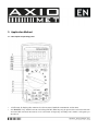
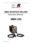
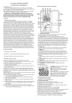
Axiomet AX-150
1. Safety Notices
The instrument meets IEC 1010 clauses (the safety standards promulgated by International Electrotechnical Commission) in terms of design, and shall be used after reading the safety notices.
• Don’t input an extreme voltage exceeding the true effective value of DC1000V or AC700V when measuring the voltage;
• The voltage of below 36V is safe. When the voltage measured is higher than DC36V or AC25V, users
shall check when the multimeter probe is reliably contacted, correctly connected, and well insulated, in
order to avoid electric shock;
• The multimeter probe shall be taken away from the tested point if the function and range are changed;
• Select correct function and range to avoid misoperation. The instrument of this series has full-range
protection function, but for the sake of safety, you shall still pay attention to this point;
• Do not input a current higher than 10A when measuring the current.
2. Characteristics
2.1. Common characteristics
•
•
•
•
•
•
•
•
•
•
Display mode: Liquid crystal display;
Maximum display: 3999 (33/4)-bit automatic polar display;
Measuring method: Dual-integral A/D conversion;
Sampling rate: Around 3 times/ second;
Ultra-range display: Highest position displayed as “OL”;
Low voltage display: Appearance of the sign BATT
Working environment: (0~40)°C, relative humidity <80%;
Power supply: 5#, 2x 1.5V batteries;
Volume (size): 180 x 90.5 x 45mm (L x W x H);
Weight: Around 420g (including battery);
• Accessories: One User’s Manual; shock-proof sleeve, and one external packing box; one TP01 thermocouple (with temperature function), testing accessories, one pair of alligator clips, and two 1.5V
batteries.
2.2. Technical characteristics
2.2.1. Accuracy
± (a% of the reading + least significant bit); guaranteed accurate ambient temperature: (23±5)° C; relative
humidity: <75%; guaranteed calibration period: one year since the date of delivery.
2.2.2. DC voltage
Range / Accuracy / Resolution
400mV / ±(1.0%+10) / 0.1mV
4V / ±(0.5%+3) / 1mV
40V / ±(0.5%+3) / 10mV
400V / ±(0.5%+3) / 100mV
1000V / ±(0.5%+3) / 1V
Input impedance: 10 MΩ.
Overload protection: DC1000V or AC750V peak value.
2.2.3. DC millivolt
Range / Accuracy / Resolution
400mV / ±(1.0%+10) / 0.1mV
2.2.4. True effective value of AC millivolt
Range / Accuracy / Range Scope / Resolution
400mV / ±(3.0%+3) / 40Hz-1kHz / 0.1mV
2.2.5. True effective value of D\AC voltage
Range / Accuracy / Frequency Scope / Resolution
4V / ±(1.0%+3) / 40Hz-1kHz / 1mV
40V / ±(1.0%+3) / 40Hz-1kHz / 10mV
400V / ±(1.0%+3) / 40Hz-1kHz / 100mV
750V / ±(1.0%+3) / 40Hz-1kHz / 1V
Input impedance: 400mV range > 40MΩ and the other is 10 MΩ;
Overload protection: DC1000V or AC750V peak value;
Frequency response: The frequency scope for all ranges is 40Hz – 1kHz (applicable to standard sine wave
and triangle wave).
Display: True effective value (more than 200Hz for other waveforms, only for reference).
2.2.6. DC current
Range / Accuracy / Resolution
400uA / ±(1.5%+3) / 0.1uA
4000uA / ±(1.5%+3) / 1uA
40mA / ±(1.5%+3) / 10uA
400mA / ±(1.5%+3) / 100uA
10A / ±(1.5%+3) / 10mA
Maximum voltage drop measured: Full range mA: 400mV; A: 100mV;
Maximum input current: 10A (not more than 10s);
Overload protection: 0.5A/250V fuse; 10A/250V fuse.
2.2.7. True effective value of AC current
Range / Accuracy /Frequency scope / Resolution
400uA / ±(1.5%+3) / 40Hz-1kHz / 0.1uA
4000uA / ±(1.5%+3) / 40Hz-1kHz / 1uA
40mA / ±(1.5%+3) / 40Hz-1kHz / 10uA
400mA / ±(1.5%+3) / 40Hz-1kHz / 100uA
10A / ±(1.5%+3) / 40Hz-1kHz / 10mA
Maximum voltage drop measured: Full range mA: 400mV; A: 100mV;
Maximum input current: 10A (not more than 15s);
Overload protection: 0.5A/250V fuse; 10A/250V fuse.
Frequency response: The frequency scope for all grades of current is 40Hz-1kHz; (applicable to standard
sine wave and triangle wave; and that for other waveforms: more than 200Hz, only for reference).
2.2.8. Resistance
Range / Accuracy / Resolution
400Ω / ±(0.5%+3) / 0.1Ω
4kΩ / ±(0.5%+2) / 1Ω
40kΩ / ±(0.5%+2) / 10Ω
400kΩ / ±(0.5%+2) / 100Ω
4MΩ / ±(0.5%+2) / 1KΩ
40MΩ / ±(1.5%+2) / 10KΩ
Input sensitivity: 1.5V;
Overload protection: DC or AC 250V peak value.
Open circuit voltage: 400mV;
Open circuit protection: DC or AC250V peak value.
Note: When the range of 400 is used, users shall firstly make the multimeter probes in short circuit state,
obtain the resistance of the down-lead, and then reduce it from the actually measured value.
2.2.9. Capacitance
Range / Accuracy / Resolution
10nF / ±(5,0%+20) / 10pF
100nF / ±(2,0%+5) / 100pF
1uF / ±(2,0%+5) / 1nF
10uF / ±(2,0%+5) / 10nF
100uF / ±(2,0%+5) / 100nF
1000uF / ±(5,0%+5) / 1uF
2.2.10. Diode and on-off test
Range / Displayed value / Test conditions
DIODE / Voltage drop in forward direction of diode / The DC current is around 0.5mA
in forward direction, and around
1.5V in backward direction.
BUZZ / The buzzer rings for long time, and the resistance / Open-circuit voltage is around 0.5V.
between two tested points is smaller than 40±30.
Overload protection: DC or AC250V peak value.
Warning: It’s forbidden to input voltage value in this range for the sake of safety!
2.2.11. Temperature
Range / Accuracy / Resolution
(-20 1000) ℃ / <400°C 1. 0%+5) / 1 ℃
≥400ı±(1. 5%+15)
(-4-1832) ° F / <752ı±(1. 0%+5) / 1 ° F
≥ 752°F±(1.5%+15)
Sensor: K type (nickel chromium- nickel silicon)
Warning: It’s forbidden to input voltage value in this range for the sake of safety!
3. Application Method
3.1. Description of operating panel
• 1. LCD unit: It displays the numerical value measured with the instrument and its unit;
• 2-1 “HzDUTY” key: AC/DC current and voltage DC/AC. This key may be pressed for conversion into AC
current if DC current is measured, or for conversion of frequency and duty ratio (1-99% ) if frequency is
measured.
• 2-2 Voltage, current and capacitance level key: After this functional switch is pressed, the reading will
be zeroed, and the product will step into the measurement of relative value, and the display unit will
show the sign “REL”; and after this key is pressed once more, the product will exit from the measurement
of relative value;
• 2-3 RANGE key: This key is used for selection of automatic or manual range. The instrument is in the
state of automatic range initially, and shows the sign “AUTO”. After this functional switch is pressed,
it will turn into manual range. The level will be increased by one every time when the key is pressed,
and it will recycle from low to high in turn. After the key is pressed for more than 2s continuously, the
product will return to the state of automatic range;
• 2-4 HOLD key: After this functional switch is pressed, the current numerical value measured with the
instrument will be held on the LCD unit, which will show the sign “HOLD”; and after this key is pressed
once more, the instrument will exit from the holding state.
• 2-5 Maximum/ minimum value measurement key: The key is triggered for measurement of maximum
value, then triggered for measurement of minimum value, and triggered the second time for the measurement of the difference between the maximum and the minimum value. It recycles successively this
way;
• 2-6 The key for conversion of AC/DC current and diode/ resistance/ buzzer.
• 3. Knob switch: Used to change the measuring function and range;
• 4. Voltage, resistance, capacitance, frequency input end;
• 5. Public ground;
• 6. Socket for test of less than 400mA current;
• 7. 10A current test socket.
3.2. DC voltage measurement
• Insert the black multimeter probe into “COM” end, and the red multimeter probe into “VHz” end;
• Convert the functional switch to the voltage level;
• The instrument is initially in the state of automatic range, and displays the sign “AUTO”; after “RANGE”
key is pressed, it will turn into the mode of manual range, and the ranges 400mV, 4V, 40V, 400V, and
1000V are optional;
• Make the testing multimeter probe contact the tested point, and the voltage and polarity of this point
contacted by the red multimeter probe will be displayed on the screen.
Notes
• Under the mode of manual range, if the LCD displays “OL”, it indicates going beyond the range, and
“RANGE” key shall be rotated to a higher level;
• The voltage measured shall never exceed DC1000V, or the instrument circuit will possibly be damaged;
• Never contact the high-voltage circuit measured.
3.3. DC millivolt voltage measurement
• Insert the black multimeter probe into “COM” end, and the red multimeter probe into “VHz” end;
• Convert the functional switch to “mV” level;
• The instrument doesn’t show the sign “AUTO”, and this level of voltage may be used for measurement
only when the voltage is no bigger than 400mV;
• Make the testing multimeter probe contact the tested point, and the voltage and polarity of this point
contacted by the red multimeter probe will be displayed on the screen.
Notes
• If LCD shows “OL”, it indicates going beyond the range, and here, AUTO DC voltage level of the
automatic range shall be used for measurement.
• Never use high-voltage DC400mV for measurement at this level.
3.4. AC millivolt true effective voltage measurement
• Insert the black multimeter probe into “COM” end, and the red multimeter probe into “VHz” end;
• Rotate functional switch to “mV” level, and press “SELECT” key to display ACmV. At this level, there is
no the sign “AUTO”. Users shall never use this level for measurement in case of AC voltage higher than
400mV;
• Make the testing multimeter probe contact the tested points, and the voltage of the two points contacted
by the multimeter probe will be displayed on the screen.
Notes
• When LCD shows “OL”, it indicates going beyond the range, and the product shall be turned to automatic
AC voltage measurement.
• Never use a voltage of higher than AC400mV for measurement at this level, or the instrument will be
damaged.
3.5. True effective value measurement of AC voltage
• Insert the black multimeter probe into “COM” end, and the red multimeter probe into “VHz” end;
• Rotate the functional switch to “V” level;
• The instrument is initially in the state of automatic range, and displays the sign “AUTO”; after “RANGE”
key is pressed, it will turn into the mode of manual range, and the ranges 400mV, 4V, 40V, 400V, and
750V are optional;
• Make the testing multimeter probe contact the tested points, and the voltage of the two points contacted
by the multimeter probe will be displayed on the screen.
Notes
• Under the mode of manual range, if the LCD displays “OL”, it indicates going beyond the range, and
“RANGE” key shall be rotated to a higher level;
• The voltage measured shall never exceed AC750V, or the instrument circuit will possibly be damaged;
• Never contact the high-voltage circuit measured.
3.6. DC current measurement
• Insert the black multimeter probe into “COM” hole, and the red multimeter probe into “mA” or “10A”
hole (maximum 400mA or 10A);
• Rotate the functional switch to current level, press “SELECT” key to select DC measurement mode, and
then connect the probe of the instrument to the tested circuit. The current value tested and the current
polarity of the point contacted by red probe will be displayed on the screen simultaneously.
Notes
• If having no idea about the scope of current measured, users shall rotate the range switch to the highest
level, and then rotate it to corresponding level according to the value displayed;
• If LCD shows “OL”, it indicates going beyond the range, and the range switch shall be rotated to a higher
level.
• The maximum input current is 400mA or 10A (depending on the inserting location of red probe). In case
of exceeding rated current, the fuse will be melted or even the instrument will be damaged.
• It’s forbidden to input voltage exceeding DC36V or AC25V peak value at “COM” and “mA” or “A” end.
3.7. True effective value measurement of AC current
• Insert the black multimeter probe into “COM” hole, and the red multimeter probe into “mA” or “10A”
hole (maximum 400mA or 10A);
• Rotate the functional switch to current level, press “SELECT” key to select AC measurement mode, and
then connect the probe of the instrument to the tested circuit. The current value tested will be displayed
on the screen simultaneously.
Notes
• If having no idea about the scope of current measured, users shall rotate the range switch to the highest
level, and then rotate it to corresponding level according to the value displayed;
• If LCD shows “OL”, it indicates going beyond the range, and the range switch shall be rotated to a higher
level.
• The maximum input current is 400mA or 10A (depending on the inserting location of red probe). In case
of exceeding rated current, the fuse will be melted or even the instrument will be damaged.
• It’s forbidden to input voltage exceeding DC36V or AC25V peak value at “COM” and “mA” or “A” end.
3.8. Resistance measurement
• Insert the black multimeter probe into “COM” hole, and red multimeter probe into “VHz” hole;
• Rotate the functional switch to “” level, and make the two multimeter probes bridge over the resistance
tested;
• Press “RANGE” key to select automatic or manual mode;
• If the resistance of small value is measured, users shall make the multimeter probe in short circuit
state, press “REL” key once, and then, measure the unknown resistance. In this way, can we obtain the
actual value of resistance.
Notes
• Under the mode of manual range measurement, if having no idea about the scope of resistance measured,
users shall adjust the switch to the highest level;
• If LCD shows “OL”, it indicates going beyond the range, and users shall adjust the range to a higher
level. If the resistance measured is more than 1M, it will take several seconds for the reading to become
stable, and this is normal for measurement of high resistance;
• If the input end is open-circuited, the overload sign “OL” will be displayed;
• The online resistance measurement may be started after it’s confirmed that, all power sources of tested
circuit are cut off, and all capacitors are completely discharged;
• Never input voltage at resistance level.
3.9. Capacitance measurement
•
•
•
•
Rotate the functional switch to “CAP” level;
Insert the black multimeter probe into “COM” hole and red multimeter probe into “VHz” hole;
If the value displayed on the screen is not 0, press “REL” key for zeroing;
Insert the corresponding polarity of tested capacitor into “VHz” hole of testing multimeter probe (the
polarity of red multimeter probe is “+”), and connect the negative end of tested capacitor into “COM”.
Here, the screen will display the capacity of capacitor.
Notes
• For each test, “REL” key must be pressed once for zeroing, in order to ensure the accuracy of measurement;
• Capacitance level has only the working mode of automatic range;
• Tested capacitor shall be completely discharged, for fear of damaging the instrument;
3.10. Frequency measurement
Frequency measurement is only applicable to AC220V, AC380 power supply, and the low-frequency and
high-voltage measurement, but not applicable to high-frequency low-voltage measurement. Press “SELECT” key to convert frequency and duty ratio, and display the frequency or duty ratio reading of tested
signal.
Notes
• Frequency has only the working mode of automatic range;
• If a value exceeding the effective value of AC10V is input, the reading will be presented, but it will
possibly be overproof;
• It’s better to use shielded cable for measuring small signals in noise environment.
• Never contact the high-voltage circuit measured.
3.11. Diode and on-off test
• Insert the black multimeter probe into “COM” hole and red multimeter probe into “VHz” hole (the
polarity of red multimeter pole is “+”;
• Rotate the functional switch to “DIODE” or “BUZZ” level;
• Measurement in forward direction: Connect the red/black multimeter probe to the positive/ negative
pole of the tested diode, and the display unit will display the approximate value of the voltage drop in
forward direction of the diode;
• Measurement in backward direction: Connect the red/black multimeter probe to the negative/ positive
pole of the tested diode, and the display unit will display “OL”;
• Complete diode test includes measurement in forward and backward direction. If the tested result is
not accordant with the abovementioned, it shows that the diode is defective.
• Connect the multimeter probes to the two points of the circuit to be tested, and the resistance value is
around 50. Here, the built-in buzzer will ring.
Notes
• Don’t input voltage at “DIODE” or “BUZZ” level.
3.12. Temperature measurement
• Rotate the functional switch to “TEMP” level.
• Insert the thermocouple sensor’s cold end (free end) negative pole (black plug) into “COM” end, and its
working end (temperature measuring end) positive pole (red plug) into “VRHz” hole. Then, arrange it
at the place where the temperature is measured, the display screen will show the temperature value of
this place measured, with the reading presented in Celsius degree; while if “SELECT” key is pressed,
the reading will be presented in Fahrenheit degree.
Notes
• Normal temperature will be displayed if the input end is open-circuit.
• Never change the temperature sensor, or the accuracy of measurement won’t be guaranteed.
• Never input voltage at temperature level.
3.13. Data holding
Press “HOLD” switch to make present data held on the display unit, and press it once again to cancel the
data holding and restart counting.
3.14. Automatic power off
• If being left unused for 15min, the instrument will be powered off automatically, and then enter into
sleep state, but in 1min before power-off, the built-in buzzer will give a prompt by ringing for five times;
later, the power supply may be restarted by pressing any key.
• Press “select” key before starting the machine may cancel the function of automatic power-off.
4. Maintenance of the Instrument
This instrument is precise, and users shall never change its circuit at random.
• Protect the instrument from water, dust and hurl-down.
• Never store or use the instrument in high-temperature, high-humidity, flammable, explosive and
strong-magnetic-field environment;
• Please clean the outer surface of the instrument with wet fabric and gentle detergent, instead of grinding
additives and strong solvents like alcohol, etc.;
• If the instrument is left unused for long term, the battery shall be taken out in order to avoid that the
instrument is eroded by battery weeping;
• Pay attention to the use of battery, and replace the battery if LCD displays the sign “BATT”; The steps
are as follows:
- Screw out the screws for fastening the battery on back cover, and remove the battery door;
- Replace the 9V batteries with two new batteries. Any standard 9V battery is available, but it’s best
to use alkalic batteries in order to extend the service life.
- Install the battery door and fasten the screws;
• Fuse replacement: The steps are the same as above. For replacement of fuse, please use fuse of the
same specification and model.
Notes
• Don’t connect the voltage higher than DC1000V or AC750V peak value;
• Don’t measure voltage value at AC, resistance, diode, and buzzer levels;
• Don’t use this instrument is the batteries are not installed or the back cover is not fastened;
• Please move the testing probes from tested points and shut down the machine before replacement of
batteries or fuse.
5. Troubleshooting
If your instrument does not work normally, the following methods may help you solve common problems.
If the troubles can not still be eliminated, please contact our maintenance center or dealer.
Fault phenomena - Position to be inspected and method
No display - The power supply is not connected; Holding switch; Replace the batteries.
Appearance of the sign ”BATT” - Replace the batteries.
No input of current - Replace the fuse.
Big error in display - Replace the batteries.