1
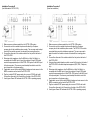
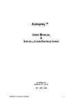
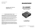
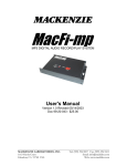
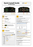
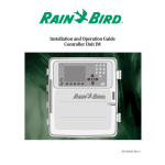
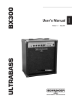
NOTES ____________________________________________________________________ ____________________________________________________________________ ____________________________________________________________________ ____________________________________________________________________ DVTEL-3100 User's Manual Version 1.0 Revised 1/6/2005 Doc 99-20-183 - $25.00 ____________________________________________________________________ ____________________________________________________________________ ____________________________________________________________________ ____________________________________________________________________ OTHER MACKENZIE PRODUCT LINES Digital Message Repeaters - Mackenzie's line of Digital Message repeaters are the ideal audio announcement solutions for Public Address, Amusement, Entertainment, Museum and Exhibit applications. Self contained solid state systems offer unparalleled reliability. A variety of channel, connection, bandwidth and memory configurations are available. Controls and Peripherals - Many applications require additional equipment to optimize the performance of Mackenzie products. This area focuses on items developed or sourced for their compatibility, ease of use and value. Included are, input/output controllers, speakers, amplifiers, motion sensors and pushbuttons among others. Transit - Mackenzie is making a difference in transit applications with innovative solutions for ADA compliance and Passenger Information Systems. These products address a variety of audio and text messaging requirements and support both in-vehicle and wayside installations. Overhead Page Management - Mackenzie's OPM and FE series of Digital Page Stacker/Repeater and Feedback Eliminators offer advanced features for the most difficult paging and intercom applications. A unique design makes feedback virtually impossible by recording then repeating pages which opens the loop between the input microphone and speakers. Various models are available to support simple repetition, multiple page stacking and multiple input channels. 12 ***Unit shown includes optional LCD user interface*** Please leave this manual with the system after installation Important warranty information enclosed 1 General Safety Instructions: Always follow these basic safety precautions when using the system: Read carefully and understand all instructions. Follow all warnings and instructions marked on the product. DO NOT block or cover ventilation slots and openings. DO NOT place the product in a closed enclosure or cabinet unless proper ventilation is provided. Never spill liquid on the product or drop objects into the ventilation slots and openings. Doing so my result in serious damage to the components. Repair or service must be performed by a factory authorized repair facility. DO NOT staple or otherwise attach the power supply cord to building surface. DO NOT use the product near or in wet or damp places, such as wet basements. DO NOT use extension cord. Install within 6 feet of a grounded outlet receptacle. DO NOT install during lightning storm. Never touch un-insulated wires or terminals unless the unit is disconnected from both power and the rest of the phone system. Use Caution when installing or modifying configuration switches or control lines. The unit must be securely attached to a wall board, rack or table mounted. Regulations: FCC (Part 15) Radio Frequency Interference The DVTEL-3100 generates and uses radio frequency energy and if not installed and used in strict accordance with the manufacturer's instructions, may cause interference to radio and television reception. Unit complies with the limits for Class A devices in accordance with the specifications in Subpart J of Part 15 of the FCC Rules. This testing is designed to provide reasonable protection against such interference. However, there is no guarantee that interference will not occur in a particular installation. If this equipment does cause interference to radio or television reception, which can be determined by turning the unit off and on, the user is encouraged to try to correct the interference by one or more of the following measures: Reorient the radio or TV receiving antenna. Relocate the unit with respect to the radio or TV receiver or vice-versa. Plug the unit into a different outlet so that it and the radio or TV receiver are on different branch circuits If necessary, the user should consult the dealer or an experienced radio/television technician for additional suggestions. 2 MAINTENANCE, WARRANTY & SERVICE The industrial grade housing and quality construction of the Mackenzie DVTEL3100 virtually eliminates the need for service or maintenance. There are no user-serviceable components within the Mackenzie DVTEL-3100. Refer all servicing to the factory. Warranty Coverage: The Mackenzie DVTEL-3100 is tested and checked before shipment and are guaranteed against defective material or workmanship for a period of three (3) year from the date of purchase. Should trouble ever develop, contact the Factory directly by telephone or in writing. If it is determined that the equipment requires Factory service, return it to the Factory. If our inspection shows that the trouble was caused by defective material or workmanship, we will repair or replace the equipment without charge and return prepaid. Repairs made necessary by abuse, improper use, unauthorized service or maintenance, and/or improper installation, as well as out of warranty repairs, will be charged at our regular repair prices in effect at the time. The obligation under this warranty shall be limited to the replacement, repair or refund of any such defective device within the warranty period. This warranty is in lieu of and excludes all other warranties, expressed or implied, and in no event shall MACKENZIE be responsible for damage to other equipment or property, for any anticipated profits, consequential damages, loss of item, or other operation or use of this product, and MACKENZIE'S maximum liability shall not ever be greater than the price paid for the equipment. This warranty gives you specific legal right. Your rights may vary from state to state. Inquiries regarding use, repair and service should be made to: MACKENZIE LABORATORIES, INC. 1163 Nicole Court, Glendora, CA 91740 USA Telephone: (909) 394-9007 / FAX No: (909) 394-9411 What we ask you to do: To get warranty service for your DVTEL-3100 system, you must provide proof of the date of original purchase. In the event you need to ship your DVTEL-3100 system to the factory for service, call us for a return authorization number. When you ship your DVTEL-3100 system, you must prepay all shipping cost. We suggest that you retain your original packing material in the event that you need to ship your DVTEL-3100 system. When sending your DVTEL-3100 system to the factory, include your name, address, phone number, proof of date of purchase, and a description of the operating problem. After repairing or replacing your DVTEL-3100 system, we will ship it to your return address at no cost to you within the USA. Repair or replacement of your DVTEL-3100 system at our factory is your exclusive remedy. What this warranty does not cover: This warranty does not cover defects resulting from accidents, damage while in transit to factory, alterations, unauthorized repairs, failure to follow instructions, misuse, fire, flood, and acts of God. 11 Specifications: Audio Quality: Dynamic Range: Frequency Resp.: THD: Audio Output: Line Level: Amplified: Gain: Features: Description: 85dB 20Hz to 20kHz @ 128kbps <0.01% at 1kHz RCA, transformer isolated, 600 ohm Terminal, 4 watts into 8 ohm Adjustable Mixing, Volume, Fade, Tone, Interval, Preceding / Proceeding message BGM Input: Mono, RCA, transformer isolated, 600 ohm with adjustable level. Audio Memory: 16MB FLASH Power: Input Voltage: Current: Connection: 12VDC 1 amp 2.5mm Barrel Compression: MPEG I Layer II Modem: Internal, 33.6k baud DVTEL-3100 Features & Benefits: Digital Transfer – Message material is transferred utilizing Z-Modem, an error correcting digital protocol. This method insures and confirms that messages are received correctly and offers various audio quality levels, independent of phone line conditions. MPEG Compression – Audio is stored in MPEG I Layer II format. This industry recognized and approved standard offers a variety of signal quality levels from voice to CD while compressing data up to 10:1 which minimizes transfer time. Built-in Fax Switch – Foolproof, proprietary fax switching technique eliminates the need for a dedicated phone line. Mechanical: Table top/wall mount configuration Dimensions - 10” W x 8” D x 1.5” H 18 gauge cold rolled steel chassis Texture coated paint process Regulatory Agency Approvals: The DVTEL-3100 system is a powerful audio messaging system intended for message on hold(MOH) and storecasting applications. Once properly installed, no further interaction from the user is required. DVTEL-3100 is designed to be operated remotely by the messaging provider. This eliminates the need for tape distribution because all audio information and configuration settings are downloaded over telephone lines. Background Music Input – Allows external music feed to be mixed with messaging content. Flash Memory – This non-volatile memory protects your messages from power loss without battery backup. If power is lost, audio playback resumes automatically once power is restored. Monitor Speaker and Level Controls – Local speaker and manual level controls expedite installation by allowing settings to be monitored in real time. FCC, Part 15, Class A UL/CSA approval on external power pack 3 10 LED Indicators: Installation: There are three installation procedures available, depending on the phone line used. We recommend Procedure A(fax share line). Power Power On Flash Installation Procedure A if the installation phone line is shared with a fax machine. The fax machine must be set to answer on or after the second ring. TX(Transmit) and RX(Receive) RNG DTR DCD CH1 PLY CH1 PLY Flash System initialized correctly System did not initialize correctly – Call technical support System is receiving a download Flash ON ON ON OFF Line is ringing Host is logging on Host is connected Message is playing Message is NOT playing Installation Procedure B if the unit is to be installed on a phone line dedicated to the DVTEL-3100. Installation Procedure C if the installation phone line is also used as a normal voice line. Keep in mind that whichever installation procedure is used, the DVTEL-3100 must always be connected directly to the telephone company input, ahead of any other devices using that line. Troubleshooting: Problem/Symptom Solution Power LED Flashing System did not initiate properly, contact technical support - Verify the correct output Line Out(600ohm) or Spkr Out(8ohm) is being used. - Increase the level with the Output Level potentiometer. - Contact provider to have them download a greater output volume setting. -DVTEL-3100 may be receiving a download, check the TX,DTR,RX,DCD indicators. -Verify connections from the Fax connection on the back of the DVTEL-3100. Output level is too low The Fax/Telephone line attached to the DVTEL-3100 does not work. 4 9 Installation Procedure A (Fax Share Installation) Final Installation Check the Power LED located just above the power connector, on the top of the DVTEL-3100: - If it is on(steady) the system has initialized correctly. If it is flashing, the system did not initialize correctly, call technical support. Contact provider for activation and message download. - DTR (Data Terminal Ready) is ON, provider is attempting to log onto the system. DCD(Data Carrier Detect) is ON, provider has successfully logged onto the system. TX(Transmit) and RX(Receive) are Flashing, provider is downloading configuration and message information. RNG(Ring) flashes when a call is coming in on the line. TX, DTR, RX, DCD are all OFF, provider has completed download Testing messages and setting levels. - - - Select Internal Monitor Speaker Switch 1 to verify message plays on the internal speaker. The LED located just above the switch, on the top of the DVTEL-3100, will be ON while messages play. Call into the phone system and ask to be placed on hold. While listening to the on hold audio, adjust the message volume (if necessary) using the Output Volume potentiometer on the top of the DVTEL-3100. If Music Input is utilized, adjust its volume (if necessary) using the BGM Level potentiometer on the top of the DVTEL-3100. When levels are correct, disconnect from the phone system and switch the Internal Speaker to OFF. The system is successfully installed. Note 1: The Output Volume and Music Input Volume potentiometers have a range of +/- 3dB from the value set during activation. If a value greater or less than this range is needed, contact provider to have the new value downloaded. Note 2: Output Volume is the master for both messaging and music and should be set prior to the Music Input Volume. 8 1. Make sure power is disconnected from the DVTEL-3100 system. 2. Connect one end of a modular telephone cable directly to the phone company box for the installation phone number. The DVTEL-3100 must be connected before the fax machine. The user may need to adapt the end of the modular connector to mate with the incoming phone line. 3. Connect the other end of the modular cable to the Line jack on the back of the DVTEL-3100. 4. Using another modular telephone cable, connect the Fax jack on the back of the DVTEL-3100 to the fax machine. 5. Determine which impedance, Line Out(600ohm) or Spkr Out( 8ohm), is compatible with the MOH input of your phone system. Using a RCA cable, connect the appropriate output of the DVTEL-3100 system to the MOH input of the phone system. The user may need to adapt the cable to match the input connection on the phone system. 6. If applicable, connect the line level(600ohm) background music source to the BGM In connection on the back of the DVTEL-3100. 7. Plug the included 12VDC power supply into a normal 110VAC wall outlet. Connect the other end to the Power jack on the back of the DVTEL-3100. 8. A solid green Power LED indicates the DVTEL-3100 is operating properly. 9. Set the fax machine to answer at a minimum of two rings. 5 Installation Procedure B (Line Dedicated to DVTEL-3100) Installation Procedure C (Voice line installation) 1. Make sure power is disconnected from the DVTEL-3100 system 2. Connect one end of a modular telephone cable directly to the phone company box for the installation phone number. The user may need to adapt the end of the modular connector to mate with the incoming phone line. 3. Connect the other end of the modular cable to the Line jack on the back of the DVTEL-3100. 4. Determine which impedance, Line Out(600ohm) or Spkr Out( 8ohm), is compatible with the MOH input of your phone system. Using a RCA cable, connect the appropriate output of the DVTEL-3100 system to the MOH input of the phone system. The user may need to adapt the cable to match the input connection on the phone system. 5. If applicable, connect the line level(600ohm) background music source to the BGM In connection on the back of the DVTEL-3100. 6. Plug the included 12VDC power supply into a normal 110VAC wall outlet. Connect the other end to the Power jack on the back of the DVTEL-3100. 7. A solid green Power LED indicates the DVTEL-3100 is operating properly. 1. Make sure power is disconnected from the DVTEL-3100 system. 2. Connect one end of a modular telephone cable directly to the phone company box for the installation phone number. The DVTEL-3100 must be connected before any other telephone equipment. The user may need to adapt the end of the modular connector to mate with the incoming phone line. 3. Connect the other end of the modular cable to the Line jack on the back of the DVTEL-3100. 4. Using another modular telephone cable, connect the Fax jack on the back of the DVTEL-3100 to the other telephone equipment (KSU, PBX, Telephone, etc.). 5. Determine which impedance, Line Out(600ohm) or Spkr Out( 8ohm), is compatible with the MOH input of your phone system. Using a RCA cable, connect the appropriate output of the DVTEL-3100 system to the MOH input of the phone system. The user may need to adapt the cable to match the input connection on the phone system. 6. If applicable, connect the line level(600ohm) background music source to the BGM In connection on the back of the DVTEL-3100. 7. Plug the included 12VDC power supply into a normal 110VAC wall outlet. Connect the other end to the Power jack on the back of the DVTEL-3100. 8. A solid green Power LED indicates the DVTEL-3100 is operating properly. 6 7