1
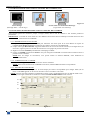
MODELS: CTX8022 & CTX8022-D
MODELS: EVX8022, EVX8022-D
& EVX8022HD-D
User’s Manual
Manuel Utilisateur
ANALOG WAY®
CENTRIX™ & EVENTIX™
EDITION : 07/05
CENTRIX™ & EVENTIX™
TABLE OF CONTENTS
SAFETY INSTRUCTIONS...........................................................................................................................................................4
Chapter 1 : INTRODUCTION.......................................................................................................................................................7
1-1. SUPPLIED EQUIPMENT..................................................................................................................................................7
1-2. GENERAL INFORMATION.............................................................................................................................................7
1-3. REFERENCES ...................................................................................................................................................................8
1-4. OPTIONAL ACCESSORIES.............................................................................................................................................8
1-5. CENTRIX™ / EVENTIX™ INSTALLATION....................................................................................................................8
1-6. CENTRIX™ FRONT PANEL DESCRIPTION..................................................................................................................9
1-7. EVENTIX™ FRONT PANEL DESCRIPTION..................................................................................................................9
1-8. REAR PANEL DESCRIPTION .......................................................................................................................................10
Chapter 2 : CONNECTING .........................................................................................................................................................11
2-1. CONNECTING THE CENTRIX™ / EVENTIX™ ............................................................................................................11
2-2. CONNECTING A CONTROL DEVICE FOR USING THE REMOTE CONTROL SOFTWARE ...............................15
2-3. CONNECTING THE REMOTE KEYPAD .....................................................................................................................15
Chapter 3 : OPERATING MODE................................................................................................................................................16
3-1. OPERATING WITH THE REMOTE CONTROL SOFTWARE ....................................................................................16
3-2. OPERATING WITH THE FRONT PANEL OF THE EVENTIX™ ................................................................................27
3-3. OPERATING WITH THE REMOTE KEYPAD .............................................................................................................33
Chapter 4 : UPDATING...............................................................................................................................................................38
4-1. CONNECTIONS ..............................................................................................................................................................38
4-2. UPDATE INSTRUCTIONS.............................................................................................................................................38
Chapter 5 : USING FRAME STORE AND LOGO INSERTION...............................................................................................39
5-1. USING LOGO INSERTION WITH THE REMOTE CONTROL SOFTWARE ............................................................39
5-2. USING FRAME STORE WITH THE REMOTE CONTROL SOFTWARE ..................................................................40
5-3. USING LOGO INSERTION WITH THE REMOTE KEYPAD OR EVENTIX™ ..........................................................41
5-4. USING FRAME STORE WITH THE REMOTE KEYPAD OR THE EVENTIX™ .......................................................42
Chapter 6 : EVENTIX™ & REMOTE KEYPAD LCD SCREEN DESCRIPTION ....................................................................43
6-1. INTRODUCTION ............................................................................................................................................................43
6-2. LCD CONTROL BUTTONS ...........................................................................................................................................43
6-3. STATUS MODE...............................................................................................................................................................43
6-4. CONTROL MODE...........................................................................................................................................................44
6-5. LCD FUNCTIONS DESCRIPTION ................................................................................................................................48
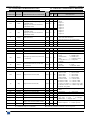
Chapter 7 : TECHNICAL SPECIFICATIONS............................................................................................................................59
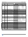
7-1. COMPUTER & VIDEO INPUTS ....................................................................................................................................59
7-2. MAIN & PREVIEW OUTPUTS ......................................................................................................................................60
7-3. COMMUNICATION PORTS & TALLY OUTPUTS .....................................................................................................60
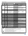
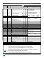
7-4. OPTIONAL VIDEO OUTPUTS (OPT-iX-SDTVD1) .....................................................................................................61
7-5. OPTIONAL AUDIO INPUTS (OPT-iX-A).....................................................................................................................62
7-6. OPTIONAL AUDIO OUTPUT (OPT-iX-A) ...................................................................................................................62
7-7. HDTV OUTPUTS (EVX8022HD-D model only)............................................................................................................62
7-8. ENVIRONMENTAL........................................................................................................................................................62
APPENDIX A: PROGRAMMER'S GUIDE .............................................................................................................................120
WARRANTY.............................................................................................................................................................................130
PAGE 3
CENTRIX™ & EVENTIX™
ENGLISH
SAFETY INSTRUCTIONS
All of the safety and operating instructions should be read before the product is operated and should be retained for further
reference. Please follow all of the warnings on this product and its operating instructions.
CAUTION:
WARNING:
To prevent the risk of electric shock and fire, do not expose this device to rain, humidity or intense
heat sources (such as heaters or direct sunlight). Slots and openings in the device are provided for
ventilation and to avoid overheating. Make sure the device is never placed on or near a textile
surface that could block the openings. Also keep away from excessive dust, vibrations and shocks.
POWER:
Only use the power supply indicated on the device or on the power source. Devices equipped with a
grounding plug should only be used with a grounding type outlet. In no way should this grounding
be modified, avoided or suppressed.
POWER CORD: Use the On (I) / Off (O) switch to power On or Off devices equipped with that switch. All other
devices should be plugged and unplugged from wall outlet. In both cases, please follow these
instructions:
- The power cord of the device should be unplugged from the outlet when left unused for several
days.
- To unplug the device, do not pull on the power cord but always on the plug itself.
- The outlet should always be near the device and easily accessible.
- Power supply cords should be routed so that they are not likely to be walked on or pinched by
items placed upon or against them.
If the power supply cord is damaged, unplug the device. Using the device with a damaged power
supply cord may expose you to electric shocks or other hazards. Verify the condition of the power
supply cords once in a while. Contact your dealer or service center for replacement if damaged.
CONNECTIONS: All inputs and outputs (except for the power input) are TBTS defined under EN60950.
SERVICING:
Do not attempt to service this product yourself by opening or removing covers and screws since it
may expose you to electric shocks or other hazards. Refer all problems to qualified service
personnel.
OPENINGS:
Never push objects of any kind into this product through the openings. If liquids have been spilled
or objects have fallen into the device, unplug it immediately and have it checked by a qualified
technician.
PAGE 4
CENTRIX™ & EVENTIX™
INSTRUCTIONS DE SÉCURITÉ
Afin de mieux comprendre le fonctionnement de cet appareil nous vous conseillons de bien lire toutes les consignes de sécurité et de fonctionnement de
l’appareil avant utilisation. Conserver les instructions de sécurité et de fonctionnement afin de pouvoir les consulter ultérieurement. Respecter toutes les
consignes marquées dans la documentation, sur le produit et sur ce document.
INSTALLATION : Veillez à assurer une circulation d’air suffisante pour éviter toute surchauffe à l’intérieur de l’appareil. Ne placez pas l’appareil sur ou
proximité de surface textile susceptible d’obstruer les orifices de ventilation. N’installez pas l’appareil à proximité de sources de chaleur comme un radiateur
ou une bouche d’air chaud, ni dans un endroit exposé au rayonnement solaire direct, à des poussières excessives, à des vibrations ou à des chocs mécaniques.
Ceci pourrait provoquer un mauvais fonctionnement et un accident.
ALIMENTATION : Ne faire fonctionner l’appareil qu’avec la source d’alimentation indiquée sur l’appareil ou sur son bloc alimentation. Pour les appareils
équipés d’une alimentation principale avec fil de terre, ils doivent être obligatoirement connectés sur une source équipée d’une mise à la terre efficace. En
aucun cas cette liaison de terre ne devra être modifiée, contournée ou supprimée.
FRANÇAIS
ATTENTION : Afin de prévenir tout risque de choc électrique et d’incendie, ne pas exposer cet appareil à la pluie, à l’humidité et aux sources de chaleur
intense.
CORDON D’ALIMENTATION : Pour les appareils équipés d’un interrupteur général (Marche I / Arrêt O), la mise sous tension et la mise hors tension se fait
en actionnant cet interrupteur général. Pour les appareils sans interrupteur général, la mise sous tension et la mise hors tension se fait directement en connectant
et déconnectant le cordon d'alimentation de la prise murale.
Dans les 2 cas ci-dessus appliquer les consignes suivantes :
- Débrancher le cordon d'alimentation de la prise murale si vous prévoyez de ne pas utiliser l'appareil pendant quelques jours ou plus.
- Pour débrancher le cordon, tirez le par la fiche. Ne tirez jamais sur le cordon proprement dit.
- La prise d’alimentation doit se trouver à proximité de l’appareil et être aisément accessible.
- Ne laissez pas tomber le cordon d’alimentation et ne posez pas d’objets lourds dessus.
Si le cordon d’alimentation est endommagé, débranchez le immédiatement de la prise murale. Il est dangereux de faire fonctionner cet appareil avec un cordon
endommagé, un câble abîmé peut provoquer un risque d’incendie ou un choc électrique. Vérifier le câble d’alimentation de temps en temps. Contacter votre
revendeur ou le service après vente pour un remplacement.
CONNEXIONS : Toutes les entrées et sorties (exceptée l’entrée secteur) sont de type TBTS (Très Basse Tension de Sécurité) définies selon EN 60950.
RÉPARATION ET MAINTENANCE : L’utilisateur ne doit en aucun cas essayer de procéder aux opérations de dépannage, car l’ouverture des appareils par
retrait des capots ou de toutes autres pièces constituant les boîtiers ainsi que le dévissage des vis apparentes à l’extérieur, risque d’exposer l’utilisateur à des
chocs électriques ou autres dangers. Contacter le service après vente ou votre revendeur ou s’adresser à un personnel qualifié uniquement.
OUVERTURES ET ORIFICES : Les appareils peuvent comporter des ouvertures (aération, fentes, etc...), veuillez ne jamais y introduire d’objets et ne jamais
obstruer ses ouvertures. Si un liquide ou un objet pénètre à l’intérieur de l’appareil, débranchez immédiatement l’appareil et faites le contrôler par un personnel
qualifié avant de le remettre en service.
Allo scopo di capire meglio il funzionamento di questa apparecchiatura vi consigliamo di leggere bene tutti i consigli di sicurezza e di funzionamento prima
dell’utilizzo. Conservare le istruzioni di sicurezza e di funzionamento al fine di poterle consultare ulteriormente. Seguire tutti i consigli indicati su questo
manuale e sull’apparecchiatura.
ATTENZIONE : Al fine di prevenire qualsiasi rischio di shock elettrico e d’incendio, non esporre l’apparecchiatura a pioggia, umidità e a sorgenti di eccessivo
calore.
INSTALLAZIONE : Assicuratevi che vi sia una sufficiente circolazione d’aria per evitare qualsiasi surriscaldamento all’interno dell’apparecchiatura. Non
collocare l’apparecchiatura in prossimità o su superfici tessili suscettibili di ostruire il funzionamento della ventilazione. Non installate l’apparecchiatura in
prossimità di sorgenti di calore come un radiatore o una fuoruscita d’aria calda, né in un posto esposto direttamente ai raggi del sole, a polvere eccessiva, a
vibrazioni o a shock meccanici. Ció potrebbe provocare un erroneo funzionamento e un incidente.
ALIMENTAZIONE : Far funzionare l’apparecchiatura solo con la sorgente d’alimentazione indicata sull’apparecchiatura o sul suo alimentatore. Per le
apparecchiature fornite di un’alimentazione principale con cavo di terra, queste devono essere obbligatoriamente collegate su una sorgente fornita di una
efficiente messa a terra. In nessun caso questo collegamento potrà essere modificato, sostituito o eliminato.
CAVO DI ALIMENTAZIONE : Per le apparecchiature fornite di interruttore generale (Acceso I / Spento O), l’accensione e lo spegnimento
dell’apparecchiatura si effettuano attraverso l’interruttore. Per le apparecchiature senza interruttore generale, l’accensione e lo spegnimento si effettuano
direttamente inserendo o disinserendo la spina del cavo nella presa murale.
In entrambe i casi applicare i seguenti consigli :
- Disconnettere l’apparecchiatura dalla presa murale se si prevede di non utilizzarla per qualche giorno.
- Per disconnettere il cavo tirare facendo forza sul connettore.
- La presa d’alimentazione deve trovarsi in prossimità dell’apparecchiatura ed essere facilmente accessibile.
- Non far cadere il cavo di alimentazione né appoggiarci sopra degli oggetti pesanti.
Se il cavo di alimentazione é danneggiato, spegnere immediatamente l’apparecchiatura. E’ pericoloso far funzionare questa apparecchiatura con un cavo di
alimentazione danneggiato, un cavo graffiato puó provocare un rischio di incendio o uno shock elettrico. Verificare il cavo di alimentazione spesso. Contattare
il vostro rivenditore o il servizio assistenza per una sostituzione.
CONNESSIONE : Tutti gli ingressi e le uscite (eccetto l’alimentazione) sono di tipo TBTS definite secondo EN 60950.
RIPARAZIONI E ASSISTENZA : L’utilizzatore non deve in nessun caso cercare di riparare l’apparecchiatura, poiché con l’apertura del coperchio metallico
o di qualsiasi altro pezzo costituente la scatola metallica, nonché svitare le viti che appaiono esteriormente, poiché ció puó provocare all’utilizzatore un
rischio di shock elettrico o altri rischi.
APERTURE DI VENTILAZIONE : Le apparecchiature possono comportare delle aperture di ventilazione, si prega di non introdurre mai oggetti o ostruire le sue
fessure. Se un liquido o un oggetto penetra all’interno dell’apparecchiatura, disconnetterla e farla controllare da personale qualificato prima di rimetterla in
servizio.
PAGE 5
ITALIANO
ISTRUZIONI DI SICUREZZA
CENTRIX™ & EVENTIX™
SICHERHEITSHINWEISE
Um den Betrieb dieses Geräts zu verstehen, raten wir Ihnen vor der Inbetriebnahme alle Sicherheits und Betriebsanweisungen genau zu lesen. Diese
Sicherheits- und Betriebsanweisungen für einen späteren Gebrauch sicher aufbewahren. Alle in den Unterlagen, an dem Gerät und hier angegebenen
Sicherheitsanweisungen einhalten.
VORSICHT & WARNUNG
ACHTUNG: um jegliches Risiko eines Stromschlags oder Feuers zu vermeiden, das Gerät nicht Regen, Feuchtigkeit oder intensiven Wärmequellen aussetzen.
EINBAU : Eine ausreichende Luftzufuhr sicherstellen, um jegliche Überhitzung im Gerät zu vermeiden. Das Gerät nicht auf und in Nähe von
Textiloberflächen, die Belüftungsöffnungen verschließen können, aufstellen. Das Gerät nicht in Nähe von Wärmequellen, wie z.B. Heizkörper oder
Warmluftkappe, aufstellen und es nicht dem direkten Sonnenlicht, übermäßigem Staub, Vibrationen oder mechanischen Stößen aussetzen. Dies kann zu
Betriebsstörungen und Unfällen führen.
DEUTSCH
STROMVERSORGUNG : Das Gerät nur mit der auf dem Gerät oder dem Netzteil angegebenen Netzspannung betreiben. Geräte mit geerdeter
Hauptstromversorgung müssen an eine Stromquelle mit effizienter Erdung angeschlossen werden. Diese Erdung darf auf keinen Fall geändert, umgangen oder
entfernt werden.
STROMKABEL : Für Geräte mit einem Hauptschalter (Ein/Aus) erfolgt die Stromversorgung und unterbrechung mittels dieses Hauptschalters. Geräte ohne
Hauptschalter werden durch das Einstecken oder Herausziehen des Steckers in den Wandanschluß ein- oder ausgeschaltet. Für beide Fälle gelten folgende
Richtlinien :
- Den Stecker aus dem Wandanschluß herausziehen wenn Sie das Gerät mehrere Tage oder länger nicht benutzen.
- Das Kabel mittels dem Stecker herausziehen. Niemals am Stromkabel selbst ziehen.
- Die Steckdose muß sich in der Nähe des Geräts befinden und leicht zugänglich sein.
- Das Stromkabel nicht fallen lassen und keine schweren Gegenstände auf es stellen.
Wenn das Stromkabel beschädigt ist, das Gerät sofort abschalten. Es ist gefährlich das Gerät mit einem beschädigten Stromkabel zu betreiben; ein abgenutztes
Kabel kann zu einem Feuer oder Stromschlag führen. Das Stromkabel regelmäßig untersuchen. Für den Ersatz, wenden Sie sich an Ihren Verkäufer oder
Kundendienststelle.
ANSCHLÜSSE : Bei allen Ein- und Ausgängen (außer der Stromversorgung) handelt es sich, gemäß EN 60950, um Sicherheits Kleinspannunganschlüsse.
REPARATUR UND WARTUNG : Der Benutzer darf keinesfalls versuchen das Gerät selbst zu reparieren, die Öffnung des Geräts durch Abnahme der
Abdeckhaube oder jeglichen anderen Teils des Gehäuses sowie die Entfernung von außen sichtbaren Schrauben zu Stromschlägen oder anderen Gefahren für
den Benutzer führen kann. Wenden Sie sich an Ihren Verkäufer, Ihre Kundendienststelle oder an qualifizierte Fachkräfte.
ÖFFNUNGEN UND MUNDUNGEN : Die Geräte können über Öffnungen verfügen (Belüftung, Schlitze, usw.). Niemals Gegenstände in die Öffnungen
einführen oder die Öffnungen verschließen. Wenn eine Flüssigkeit oder ein Gegenstand in das Gerät gelangt, den Stecker herausziehen und es vor einer neuen
Inbetriebnahme von qualifiziertem Fachpersonal überprüfen lassen.
INSTRUCCIONES DE SEGURIDAD
Para comprender mejor el funcionamiento de este aparato, le recomendamos que lea cuidadosamente todas las consignas de seguridad y de funcionamiento del
aparato antes de usarlo. Conserve las instrucciones de seguridad y de funcionamiento para que pueda consultarlas posteriormente. Respete todas las consignas
indicadas en la documentación, relacionadas con el producto y este documento.
PRECAUCIONES Y OBSERVACIONES
ESPAÑOL
CUIDADO : Para prevenir cualquier riesgo de choque eléctrico y de incendio, no exponga este aparato a la lluvia, a la humedad ni a fuentes de calorintensas.
INSTALACIÓN : Cerciórese de que haya una circulación de aire suficiente para evitar cualquier sobrecalentamiento al interior del aparato. No coloque el
aparato cerca ni sobre una superficie textil que pudiera obstruir los orificios de ventilación. No instale el aparato cerca de fuentes de calor como radiador o
boca de aire caliente, ni en un lugar expuesto a los rayos solares directos o al polvo excesivo, a las vibraciones o a los choques mecánicos. Esto podría
provocar su mal funcionamiento o un accidente.
ALIMENTACIÓN : Ponga a funcionar el aparato únicamente con la fuente de alimentación que se indica en el aparato o en su bloque de alimentación. Los
aparatos equipados con una alimentación principal con hilo de tierra deben estar conectados obligatoriamente a una fuente equipada con una puesta a tierra
eficaz. Por ningún motivo este enlace de tierra deberá ser modificado, cambiado o suprimido.
CABLE DE ALIMENTACIÓN : Para los aparatos equipados con un interruptor general (Marcha I / Paro O), la puesta bajo tensión y la puesta fuera de tensión
se hace accionando este interruptor general.. En los aparatos que no tienen interruptor general, la puesta bajo tensión y la puesta fuera de tensión se hace
directamente conectando y desconectando el enchufe mural.
En ambos casos, se deberá respetar las siguientes consignas:
- Desconectar el aparato del enchufe mural si no piensa utilizarlo durante varios días.
- Para desconectar el cable, tire de la clavija. No tire nunca del cable propiamente dicho.
- El enchufe de alimentación debe estar cerca del aparato y ser de fácil acceso.
- No deje caer el cable de alimentación ni coloque objetos pesados encima de él.
Si el cable de alimentación sufriera algún daño, ponga el aparato inmediatamente fuera de tensión. Es peligroso hacer funcionar este aparato con un cable
averiado, ya que un cable dañado puede provocar un incendio o un choque eléctrico. Verifique el estado del cable de alimentación de vez en cuando. Póngase
en contacto con su distribuidor o con el servicio de posventa si necesita cambiarlo.
CONEXIONES : Todas las entradas y salidas (excepto la entrada del sector) son de tipo TBTS (Muy Baja Tensión de Seguridad) definidas según EN 60950
REPARACIÓN Y MANTENIMIENTO : Por ningún motivo, el usuario deberá tratar de efectuar operaciones de reparación, ya que si abre los aparatos
retirando el capó o cualquier otra pieza que forma parte de las cajas o si destornilla los tornillos aparentes exteriores, existe el riesgo de producirse una
explosión, choques eléctricos o cualquier otro incidente. Contacte el servicio de posventa, a su distribuidor o dirigirse con personal cualificado únicamente.
ABERTURAS Y ORIFICIOS : Los aparatos pueden contener aberturas (aireación, ranuras, etc.). No introduzca allí ningún objeto ni obstruya nunca estas
aberturas. Si un líquido o un objeto penetra al interior del aparato, desconéctelo y hágalo revisar por personal cualificado antes de ponerlo nuevamente en
servicio.
PAGE 6
CENTRIX™ & EVENTIX™
CENTRIX™ / EVENTIX™
Chapter 1 : INTRODUCTION
1-1. SUPPLIED EQUIPMENT
• 1 CENTRIX™ or 1 EVENTIX™.
• 1 AC power supply cord.
• 1 CD-ROM (Remote Control Software).
• 1 User’s Manual.
Supplied equipment with the OPT-iX-SDTVD1 option and the EVX8022HD-D model:
• 1 "video output" cable (DB9 M to 4BNC + mini DIN 4).
Supplied equipment with the OPT-iX-A option:
• 1 set of 11 MCO (5-pin) female connector (for audio connection).
1-2. GENERAL INFORMATION
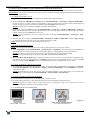
CENTRIX™ & EVENTIX™ are Computer & Video Up/Down Mixer Scaler Switchers featuring numerous Effects
(Cut, Fade, Wipes, PIP, Title) together with Hi-Res. LOGO insertion and FRAME Store functions. Fitted with 8
universal inputs, it can be used as a 8 x 2 Scaled Matrix as well as a Mixer.
MIXER MODE
CENTRIX™ & EVENTIX™ scale all the sources - video and computer - and performs seamless switching transitions
between any 2 inputs. It also realizes various effects (CUT, PIP, Fade, Title). The 2 Main outputs match the native
resolution of any videoprojector or Hi-Res. Display device, and the Preview outputs allow to monitor the sequences
before they are displayed on the main screens, preventing errors during a presentation.
PIP Effect: High performance picture insertion from any input. The PIP can be sized and moved anywhere on the
background image. Both background image and PIP can be fast & smoothly switched through a fade to black or
customized color.
FADE Effect: CENTRIX™ / EVENTIX™ features Fade, Dissolve, Black & Cut effects between any input (computer or
video). It also allows to adjust the cross-fading duration.
TITLE Effect: The title remains on the screen during the transition. The shadow title function, with settable vertical
size and position, increases readability on bright images. CENTRIX™ / EVENTIX™ enables to display a title over a
computer or a video image.
CUT: Seamless Switching between any 2 inputs.
WIPES (available with EVENTIX™ only): Numerous Horizontal and vertical wipe transitions.
NATIVE MATRIX MODE
CENTRIX™ & EVENTIX™ when used as a Hi-Res. Matrix, allow to switch any of the 8 inputs to one of the 2
outputs. The inputs are scaled and can be displayed with different resolutions on outputs 1 and 2.
FEATURES IN BOTH MATRIX & MIXER MODE
CENTRIX™ & EVENTIX™ provide you with a high quality image thanks to its integrated digital decoder, improved
3:2 and 2:2 Pull down circuitry, auto-adaptive pixel by pixel 3D motion compensation, Time Base Corrector, Frame
Rate Converter & Follower. Each input image control can be individually set and stored in non-volatile memories.
LOGO INSERTION & FRAME STORE: true Hi-Res. 16 million colors image defined either by keying or image
cut-out: The FRAME STORE and LOGO(S) can be flashed captured from any video or computer sources into a non
volatile memory. Up to 2 logos can be allocated per input and positioned anywhere on the screen. The Frame Store can
be used as a Welcome Image or as a Transition Image while switching between 2 sources.
CENTRIX™ is specially designed for Hi-res. A/V Presentation Displays, Conference Room Installations, Boardrooms
and Exhibition Centers. It offers a user-friendly interface and can be easily remote controlled & upgraded via its RS232
or TCP/IP ports, or using the optional remote keypad.
EVENTIX™ is specially designed with a Full Control front panel for Hi-res. A/V Presentation Displays, Large Events,
Rentals as well as installation. It offers a user-friendly interface and can be easily controlled & upgraded via its RS232
or TCP/IP ports, or by using the optional remote keypad.
PAGE 7
Chapter 1 : INTRODUCTION (continued)
CENTRIX™ & EVENTIX™
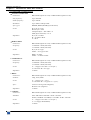
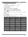
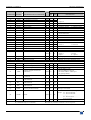
1-3. REFERENCES
MODELS &
OPTIONS
CTX8022
CTX8022-D
EVX8022
EVX8022-D
EVX8022HD-D
OPT-iX-SDTVD1
DESIGNATIONS
™
CENTRIX .
CENTRIX™ with SDI & DVI inputs.
EVENTIX™.
EVENTIX™ with SDI & DVI inputs.
EVENTIX™ with SDI & DVI inputs & HDTV outputs (HD YUV & HDSDI).
Optional SDTV video output (COMPOSITE VIDEO + S.VIDEO + YUV + SDI). This option is
available with all models except for the EVX8022HD-D model.
Optional AUDIO input/output. This option is available with all models.
CROSS BLENDER™. Optional version for "Edge blending" application. This option is available
with EVENTIX models only.
OPT-iX-A
CBD-UP
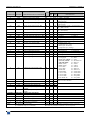
1-4. OPTIONAL ACCESSORIES
REFERENCES
RK8022
RK8022-T
TRC8022
SWM-OE
DESIGNATIONS
Remote keypad for CENTRIX™ / EVENTIX™.
Remote keypad with T-BAR for CENTRIX™ / EVENTIX™.
Remote console for CENTRIX™ / EVENTIX™. Allows to control up to 3 devices.
Remote control Software for 16 CENTRIX™ / EVENTIX™. Allows to control up to 16 devices.
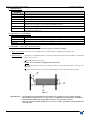
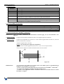
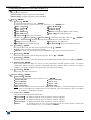
1-5. CENTRIX™ / EVENTIX™ INSTALLATION
IMPORTANT: Please read all of the safety instructions (pages 4 to 6) before starting.
• Table top mounting: The device can be used directly on a table: the unit is equipped with 4 plastic feet.
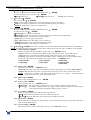
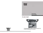
• Rack mounting:
The device is compatible with a 19” enclosure. Please follow the instructions below to install the
device in a 19” rack.
c Place the device in your rack.
NOTE: Your rack must be equipped with some braces.
d Attach the device to the rack by using 4 screws in the front panel holes (screws are not
included).
e Connect all of the cables of the device and attach them to the rack with some tie wraps.
Figure 1
IMPORTANT: -
PAGE 8
The openings in the side and in the rear panel are for cooling. Do not cover these openings.
Be sure that no weight in excess of 2 kg (4.4 Lbs.) is added onto the CENTRIX™ / EVENTIX™.
The maximum ambient operating temperature must not exceed 40 °C (104 °F).
The rack and all mounted equipment in it must be reliably grounded to national and local
electrical codes.
CENTRIX™ & EVENTIX™
Chapter 1 : INTRODUCTION (continued)
™
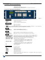
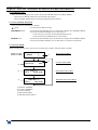
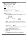
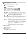
1-6. CENTRIX FRONT PANEL DESCRIPTION
POWER:
LED ON: device ON.
LED OFF: device OFF.
LED blinking slowly: update in progress.
LED blinking quickly: update/start error. You should restart the device.
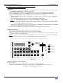
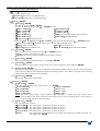
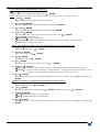
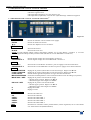
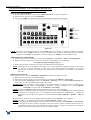
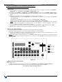
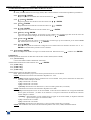
1-7. EVENTIX™ FRONT PANEL DESCRIPTION
Figure 2
LCD CONTROL
EXIT/MENU:
ENTER:
:
Switches between Status and Control mode.
Validates a selected item.
Allows scrolling thru the different menus.
INPUT SELECT
1 to 8:
Input source selection.
BLACK:
Black screen selection.
NOTE: The turn ON LED indicates the selected input (displayed on MAIN / OUTPUT 1). The blinking LED
indicates the pre-selected input (displayed on PREVIEW / OUTPUT 2).
FREEZE
MAIN/OUT 1:
PREVIEW/OUT 2:
Allows to freeze the MAIN / OUTPUT 1.
Allows to freeze the PREVIEW / OUTPUT 2.
OUTPUT
MAIN/OUT 1:
PREVIEW/OUT 2:
MAIN / OUTPUT 1 selection for adjustments or input selection.
PREVIEW / OUTPUT 2 selection for adjustments or input selection.
ADJUST
LOGO 1 POSITION:
LOGO 2 POSITION:
LOGO ON/OFF:
IMAGE CENTERING:
IMAGE POS. / SIZE:
PIP POS. / SIZE:
H:
V:
EFFECT SELECT
CUT:
PIP:
USER 1:
USER 2:
USER 3:
USER 4:
TAKE
Horizontal & Vertical logo #1 position adjustment. Adjust with H & V knobs.
Horizontal & Vertical logo #2 position adjustment. Adjust with H & V knobs.
Display ON or OFF the assigned logos of the displayed input.
Automatically position the selected source in the centering pattern.
IMAGE position & size adjustment.
• First push: position adjustment. Adjust with H & V knobs.
• Second push: size adjustment. Adjust with H & V knobs.
PIP position & size adjustment.
• First push: position adjustment. Adjust with H & V knobs.
• Second push: size adjustment. Adjust with H & V knobs.
Horizontal adjustment.
Vertical adjustment.
CUT effect selection.
PIP effect selection.
USER 1 effect selection.
USER 2 effect selection.
USER 3 effect selection.
USER 4 effect selection.
Switch the pre-selected input (blinking key) on the MAIN output with the selected
EFFECT (EFFECT KEYS).
PAGE 9
Chapter 1 : INTRODUCTION (continued)
CENTRIX™ & EVENTIX™
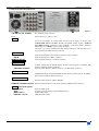
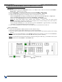
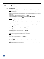
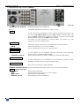
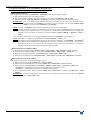
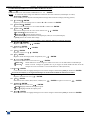
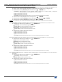
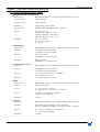
1-8. REAR PANEL DESCRIPTION
Figure 3
100-240 Vac 3A 50-60Hz:
IEC standard power connector.
O/I:
Power switch (O = OFF, I = ON)
INPUTS
1 to 8:
8 Universal Computer & Video Inputs. Each of the 8 inputs can accept both
COMPUTER sources (RGBHV, RGBS, and RGsB (SOG) signals), standard
TV/VIDEO sources (Composite video, S.VIDEO, Component (YUV), RGBS &
RGsB (SOG)), and HDTV sources (720p & 1080i).
The inputs 1 to 4 are provided with 5 BNC female connectors, and the inputs 5 to 8
are provided with a HD15 female connector.
OPTIONAL IN
DVI INPUT:
SDI IN:
Optional DVI (digital visual interface) input on a DVI connector.
Optional SDI input on a BNC connector.
REMOTE IP/LAN
LAN communication port on a RJ45 connector.
MAIN / OUTPUT 1
DISPLAY:
OPTIONAL OUTPUT:
PREVIEW / OUTPUT 2
DISPLAY:
OPTIONAL OUTPUT
OUT 1:
2 MAIN outputs for the MAIN display devices (video projector, PLASMA, data
monitor) on HD15 female connectors.
Optional video (SDTV or HDTV) output #1 on DB9 female connector.
2 PREVIEW outputs for the PREVIEW display devices (video projector, PLASMA,
data monitor) on HD15 female connectors.
Optional video output #1 (SDI or HDSDI).
REMOTE CONTROL RS-232: RS-232 communication port & 3 tally outputs (on DB9 female connector).
AUDIO (OPT-iX-A option)
IN 1 to IN 8:
AUX:
MAIN / OUT 1:
PRELIST / OUT 2:
PAGE 10
Optional audio inputs.
Auxiliary input for mixing with the diffused source
MAIN audio output.
PRELIST audio output.
CENTRIX™ & EVENTIX™
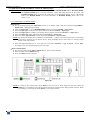
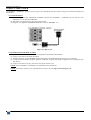
Chapter 2 : CONNECTING
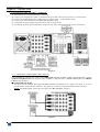
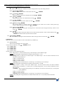
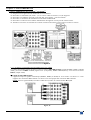
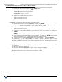
2-1. CONNECTING THE CENTRIX™ / EVENTIX™
c
d
e
f
g
h
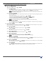
Turn OFF all of your equipment before connecting.
Connect your computers (PC, MAC, workstation) and your video sources to the inputs (1 to 8) of the device.
Connect your MAIN display device (data projector, plasma screen...) to the "MAIN" output.
Connect your control monitors to the PREVIEW & MAIN outputs.
Connect the AC power supply cord to the device and to a power outlet.
Turn ON the projector, the local monitors, the device (rear panel switch) and then all of your input sources.
Figure 4
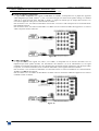
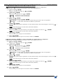
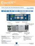
2-1-1. UNIVERSAL COMPUTER & VIDEO INPUTS
The UNIVERSAL INPUTS can accept both COMPUTER sources (RGBHV, RGBS, and RGsB (SOG) signals),
standard TV/VIDEO sources (Composite video, S.VIDEO, Component (YUV), RGBS & RGsB (SOG)), and HDTV
sources (720p & 1080i).
c COMPUTER SOURCES:
The device accepts COMPUTER signals (RGBHV, RGB/S, and RGsB) on its 8 inputs. The inputs #1 to #4 are
provided with a 5x BNC female connectors. The inputs #5 to #8 are provided with a HD15 female connector.
NOTE: For RGBS signals connect the Sync cable to the H/C sync BNC connector.
Figure 5
PAGE 11
Chapter 2 : CONNECTING (continued)
CENTRIX™ & EVENTIX™
2-1. CONNECTING THE CENTRIX™ / EVENTIX™ (continued)
2-1-1. UNIVERSAL COMPUTER & VIDEO INPUTS (continued)
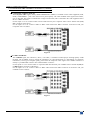
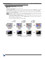
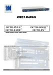
d COMPOSITE VIDEO SOURCES:
The Composite Video signal, usually called COMPOSITE or VIDEO, is available on most video equipment (VCR,
DVD, CAMCORDER…), but is also the lowest in picture quality. The video standard of this signal can be NTSC,
PAL or SECAM. The signal is transmitted on a single coaxial cable, and is connected to the video equipment with a
RCA or a BNC connector.
For the inputs #1 to #4: connect a BNC coaxial cable between your Composite video sources and the C.V (G/Y)
BNC connector of the device.
For the inputs #5 to #8: connect a HD15 to BNC cable between the HD15 connector of the device and your
Composite source as follow:
Figure 6
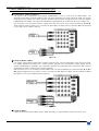
e S.VIDEO SOURCES:
The S.VIDEO signal, also called Y/C, HI-8™, or S.VHS™, is available on DVD players and high quality VCRs
(S.VHS). The S.VIDEO signal in which the Luminance (Y) and Chrominance (C) information are separately
transmitted (2 wires) gives a higher quality picture than the Composite video signal. The S.VIDEO connector is
usually a 4 pin Mini-DIN connector also called Oshiden™ connector.
For the inputs #1 to #4: connect a BNC to 4-pin mini DIN cable between your S.VIDEO sources and the Y (G/Y) &
C (R/R-Y) BNC connectors of the device.
For the inputs #5 to #8: connect a HD15 to BNC cable between the HD15 connector of the device and your
S.VIDEO source as follow:
Figure 7
PAGE 12
CENTRIX™ & EVENTIX™
Chapter 2 : CONNECTING (continued)
2-1. CONNECTING THE CENTRIX™ / EVENTIX™ (continued)
2-1-1. UNIVERSAL COMPUTER & VIDEO INPUTS (continued)
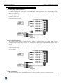
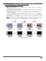
f COMPONENT VIDEO SOURCES:
The Component Video signal, also called YUV (Y, R-Y, B-Y) or BETACAM™ is widely used in broadcasting and
is available on high-quality DVD players. The COMPONENT signal is transmitted with 3 coaxial cables, and also
has a better quality picture than COMPOSITE and S.VIDEO signals. The COMPONENT connectors are usually
RCA (x3), or BNC (x3).
For the inputs #1 to #4: connect a 3 x BNC cable between your Component sources and the Y, R-Y & B-Y BNC
connectors of the device.
For the inputs #5 to #8: connect a HD15 to BNC cable between the HD15 connector of the device and your
Component source as follow:
Figure 8
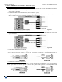
g RGBS VIDEO SOURCES:
This signal is widely used in broadcasting and is available on European DVD player. The RGB/S signal is
transmitted with 4 coaxial cables, and also has a better picture quality than COMPOSITE and S.VIDEO signals.
The RGB/S connectors are usually BNC connectors for Broadcasting equipment, and SCART connector for DVD
players.
For the inputs #1 to #4: connect a 3xBNC cable between your RGB/S sources and the R, G, B & H/C sync BNC
connectors of the device.
For the inputs #5 to #8: connect a HD15 to BNC cable between the HD15 connector of the device and your RGB/S
source as follow:
Figure 9
h HDTV SOURCES:
The device accepts the 720p & 1080i HDTV formats. Connect your HDTV signal as a Component source.
PAGE 13
Chapter 2 : CONNECTING (continued)
CENTRIX™ & EVENTIX™
2-1. CONNECTING THE CENTRIX™ / EVENTIX™ (continued)
2-1-2. MAIN (OUTPUT 1) AND PREVIEW (OUTPUT 2) OUTPUTS
The device is equipped with 2 MAIN outputs on HD15 female connector, and two PREVIEW outputs on HD15
female connector. Connect the MAIN display device onto the MAIN output. Connect the monitoring devices onto
the MAIN & PREVIEW outputs.
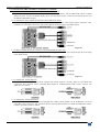
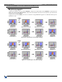
2-1-3. OPTIONAL SDTV VIDEO OUTPUTS (OPT-iX-SDTVD1 option)
The device equipped with this option provides simultaneously 4 SDTV video output signals (composite video,
S.VIDEO, YUV and SDI). These four video outputs display the same image as the MAIN output.
Figure 10
2-1-4. HDTV VIDEO OUTPUTS (available on the EVX8022HD-D model only)
The device provides simultaneously HD YUV & HDSDI signals. These two video outputs display the same image
as the MAIN output.
Figure 11
2-1-5. OPTIONAL AUDIO INPUTS
The devices with the OPT-iX-A option are equipped with 8 audio inputs & 1 auxiliary input (on 5-pin MCO male
connectors). This connector allows connecting BALANCED or UNBALANCED audio sources. Connect your
audio sources as follow:
2-1-6. OPTIONAL AUDIO OUTPUTS
The devices with the OPT-iX-A option are equipped with 2 audio outputs (MAIN / OUT1 & PRELIST / OUT2 on
5-pin MCO male connectors). This connector allows connecting BALANCED or UNBALANCED audio systems.
Connect your audio systems as follow:
PAGE 14
CENTRIX™ & EVENTIX™
Chapter 2 : CONNECTING (continued)
2-2. CONNECTING A CONTROL DEVICE FOR USING THE REMOTE CONTROL SOFTWARE
Your CENTRIX™ & EVENTIX™ are shipped with a Windows compatible Remote Control Software (3.5" disk). This
software allows you to control and make all adjustments by a simple mouse click.
NOTE: Preferably use Windows NT, 2000, or XP for LAN operation.
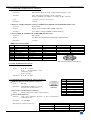
2-2-1. CONNECTING TO THE RS-232 PORT
- Connect the serial port of your control device to the RS-232 port (DB9 Female connector) of the CENTRIX™ /
EVENTIX™ with a straight cable (DB9 Female / DB9 Male).
- Speed transmission: 9600 bauds, 8 data bits, 1 stop bit, no parity bit, no flow control.
- Pin-out:
PIN #
2
3
5
FUNCTIONS
TRANSMIT DATA (Tx)
RECEIVE DATA (Rx)
GROUND (Gnd)
DB9 female (Rear panel of the CTX/EVX8022)
2-2-2. CONNECTING TO THE LAN PORT
- Connect the LAN port (RJ45 connector) of the CENTRIX™ / EVENTIX™ to your network according to your
installation.
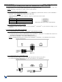
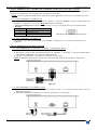
2-3. CONNECTING THE REMOTE KEYPAD
2-3-1. CONNECTING TO A CENTRIX™ / EVENTIX™ WITH THE RS-232 PORT
c Turn OFF your CENTRIX™ / EVENTIX™ (rear panel switch).
d Connect the RS-232 connector (DB9 female) of your CENTRIX™ / EVENTIX™ to the DB9 male connector of
the REMOTE KEYPAD with the supplied DB9 M/F cable.
e Turn ON your CENTRIX™ / EVENTIX™ (REAR panel switch).
NOTE: The REMOTE KEYPAD is powered by the CENTRIX™ / EVENTIX™ via its DB9 (RS-232) connector.
Figure 12
2-3-2. CONNECTING TO A NETWORK (LAN)
c Connect the power supply to a power outlet and to the DC-IN connector (rear panel).
d Connect the REMOTE KEYPAD to your network according to your installation.
Figure 13
PAGE 15
CENTRIX™ & EVENTIX™
Chapter 3 : OPERATING MODE
3-1. OPERATING WITH THE REMOTE CONTROL SOFTWARE
Your CENTRIX™ / EVENTIX™ is shipped with a WINDOWS compatible software. This software allows you to control
and make adjustments by a simple mouse click.
3-1-1. SOFTWARE INSTALLATION
c Turn your computer ON and wait for Windows to completely start.
d Insert the CD-ROM into your drive: the ANALOG WAY home window will open automatically.
e Select the language of the CD-ROM menus, then click on "Install a Remote Control Software and select a name
of your device.
IMPORTANT: If the autorun is not enabled: From the windows desktop, open My Computer and select the
CD-ROM drive. Select the Autorun folder, and then select the autorun.exe file.
f Follow the Windows installation instructions.
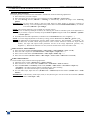
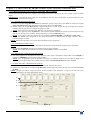
3-1-2. COMMUNICATION SETUP
• CASE OF RS-232 PORT:
c Connect the RS-232 cable between the CENTRIX™ / EVENTIX™ and the control device according to your
installation, as indicating in the section 2-2-1.
d Then only power ON all of the devices.
e Click on the program files iX8022 in Start > program >ANALOGWAY > iX8022 to run the software.
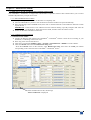
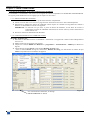
f Click on Controls menu and select RS232/LAN setup, then:
- With the Controls menu of the software, select RS232/LAN setup, then select the COM port number
corresponding to the connection of the CENTRIX™ / EVENTIX™ device.
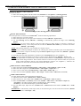
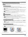
Figure 14
If the communication is OK, the message
"Device connected" is displayed.
PAGE 16
CENTRIX™ & EVENTIX™
Chapter 3 : OPERATING MODE (continued)
3-1. OPERATING WITH THE REMOTE CONTROL SOFTWARE (continued)
3-1-2. COMMUNICATION SETUP (continued)
• CASE OF LAN PORT:
c Connect the control device to the CENTRIX™ / EVENTIX™ with the RS-232 port as indicated in the previous
page, then configure the LAN communication port (local address & port, remote address & port, netmask and
gateway) of the device with the Remote Control Software (CONTROL menu > CENTRIX LAN setup).
d Connect the LAN port (RJ45 connector) of the device to your network according to your installation.
e Select the LAN communication port of the device with the remote control software (CONTROL menu >
RS232/LAN setup >LAN setup) and configure the control device (Local port, Remote IP address & Remote
Port). Click on Apply to setup the new values. The software will also display Device connected. Then you can
disconnect the RS232 cable.
NOTE: If the communication doesn't work (CENTRIX™ only), you need to reconnect the RS-232 communication port
to your control device, and restart the device. The device will also automatically detect and activate the RS232
communication port.
Figure 15
IMPORTANT: The CENTRIX™ & EVENTIX™ can be used in two different modes: the MIXER MODE and the
MATRIX MODE. The MIXER MODE allows switching seamlessly, fading and titling between all the
inputs. The MATRIX MODE allows displaying the inputs onto two independents display devices. The
default mode is the MIXER MODE. To set the CENTRIX™ / EVENTIX™ in MATRIX MODE, please
refer to the section: 3-1-4.
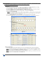
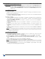
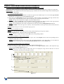
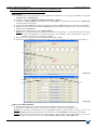
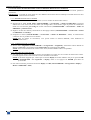
3-1-3. OPERATING IN MIXER MODE
• SETTINGS
c We recommend resetting the device to its default values (Controls menu > default value) before proceeding.
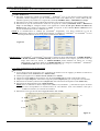
d Verify the device is set in MIXER MODE (Mode menu > Mixer).
e Click on the Input tab and select the signal type of each source connected to the inputs.
f Click on the Output tab and select the output sync. according to your display device.
g Select the output rate mode (Internal rate or follow input...). Then select the frame rate.
h Select one of the output formats.
NOTE: For fixed pixels display device (DMD, LCD, PLASMA…), always select the output format
corresponding to the native resolution of your display device. Thus, the display device will not have to
scale the image and the result will be better.
i Select the type of screen (4/3 or 16/9), according to your wall mounted projection screen shape.
g
g
h
i
f
Figure 16
PAGE 17
Chapter 3 : OPERATING MODE (continued)
CENTRIX™ & EVENTIX™
3-1. OPERATING WITH THE REMOTE CONTROL SOFTWARE (continued)
3-1-3. OPERATING IN MIXER MODE (continued)
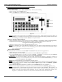
• INPUT SELECTION
c Pre-select an input with the INPUT SELECT keys. The key starts blinking.
d Select an effect with the EFFECT keys.
e Press on TAKE or move the T-BAR to do the transition.
c
e
d
Figure 17
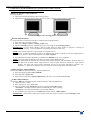
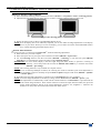
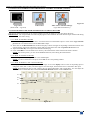
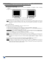
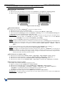
• DISPLAY DEVICES ADJUSTMENTS
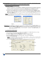
c Click on the Output tab and select the MAIN centering pattern.
d Adjust directly the display device itself, using its controls, to fill the centering pattern in full screen.
Figure 18: Centering pattern.
e Renew the same process to adjust your PREVIEW display device.
NOTE: Now the display devices are identically adjusted, you can also make the image adjustments of each source
on the display device of your choice. When you are in a live display, you can make corrections on the
PREVIEW monitor only, without disturbing the MAIN display device.
• IMAGE ADJUSTMENTS
For each input source connected to the CENTRIX™ / EVENTIX™ make the following adjustments:
c Select the source you want to adjust.
d Click on the Image main or Image preview tab.
e Use the Centering function to automatically position the image in the Centering pattern.
IMPORTANT: For best results, display a full size bright image (no black border) to perform a centering. If
necessary, correct the adjustment with the position & size functions.
NOTE: The centering function is only available for computer sources.
NOTE: In case of same Input/Output resolution, the centering also achieves automatic pixel clock adjustments. It
may be useful, to improve manually the pixel clock and phase.
f If needed, make the others adjustments, available in the IMAGE menu (color, brightness…).
NOTE: To set the image adjustments to the factory settings, use the Preset function.
NOTE: The adjustments are automatically stored in NON-volatile memories. The CENTRIX™ & EVENTIX™ are
provided with 40 NON-volatile image memories. Each of these memories contains the input channel
number, the input and output format parameters and all of the image adjustments (position, size,
brightness...). When the 40 memories are used, each new memorization erases the oldest record.
PAGE 18
CENTRIX™ & EVENTIX™
Chapter 3 : OPERATING MODE (continued)
3-1. OPERATING WITH THE REMOTE CONTROL SOFTWARE (continued)
3-1-3. OPERATING IN MIXER MODE (continued)
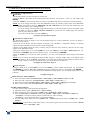
• EFFECT ADJUSTMENTS
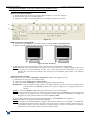
c Click on the Effects tab, then click on the Effect button and select an Effect.
d Click on the EFFECT ANIMATION button, select an Effect opening and an Effect closing, and select the
durations.
NOTE: The Effect opening and Effect closing available are write in black and depend of the selected Effect.
e Then, make the effect adjustment available in the Effects windows.
c
d
Figure 19
e
Figure 20
PAGE 19
Chapter 3 : OPERATING MODE (continued)
CENTRIX™ & EVENTIX™
3-1. OPERATING WITH THE REMOTE CONTROL SOFTWARE (continued)
3-1-3. OPERATING IN MIXER MODE (continued)
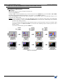
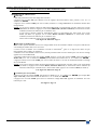
• EXAMPLES OF TRANSITION
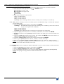
c PIP effect:
The PIP effect allows to insert an image into another one.
• Click on the Effects tab.
• Assign a PIP to one of the EFFECT keys: Click on the arrow of an EFFECT key and select PIP or PIP FADE,
then make all the needed adjustments (duration, size, position...) in the Effects windows.
• Press the TAKE key to activate the effect (ACTION 1 in the example below): the PREVIEW image is now
inserted into the MAIN image.
NOTE: • You can change the image in the PIP (PREVIEW image) by selecting another input of the PREVIEW
output (ACTION 2): Press the SWITCH PREVIEW key and select the needed input (the transition
operates with a fading to black).
• You can change the background image (MAIN image) by selecting another input of the MAIN output
(ACTION 3): Press the SWITCH MAIN key and select the needed input (the transition operates with a
fading to black).
• To remove the PIP effect, press the TAKE key.
Figure 21: PIP effect.
PAGE 20
CENTRIX™ & EVENTIX™
Chapter 3 : OPERATING MODE (continued)
3-1. OPERATING WITH THE REMOTE CONTROL SOFTWARE (continued)
3-1-3. OPERATING IN MIXER MODE (continued)
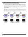
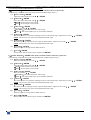
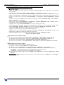
d Title effect (or shadow title):
The TITLE effect allows displaying a text onto the MAIN image. For a better readability you also can display a
shadow bar onto your text.
• Create the text to display with the computer connected to the CENTRIX™ / EVENTIX™ thanks to a drawing
software like PowerPoint® (text in white onto a black background).
• Display on the MAIN output the source to titling (INPUT #2 in the example below), then pre-select the source
used for create the text: the image appears on the PREVIEW output (INPUT #1 in the example below).
• Click on the Effects tab.
• Assign the TITLE effect to one of the EFFECT keys: Click on the arrow of an EFFECT key and select title or
shadow title, then make all the needed adjustments (duration...) in the Effects windows.
• Press the TAKE key to activate the effect (ACTION 1): the text is now displayed onto the image of the MAIN
output.
NOTE: You can change the background image (MAIN image) by selecting another input of the MAIN output
(ACTION 2): Press the SWITCH MAIN key and select the needed input (the transition operates with a
fading to black). To remove the TITLE effect, press the TAKE key (ACTION 3).
Figure 22: Title effect.
PAGE 21
Chapter 3 : OPERATING MODE (continued)
CENTRIX™ & EVENTIX™
3-1. OPERATING WITH THE REMOTE CONTROL SOFTWARE (continued)
3-1-3. OPERATING IN MIXER MODE (continued)
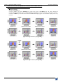
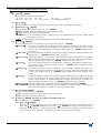
e Wipe transition:
• Click on the Effects tab.
• Assign a WIPE to one of the EFFECT keys: Click on the arrow of an EFFECT key and select a WIPE (for
example: hor wipe from left). Select an effect opening and closing then select the duration in the Effects windows.
• Press the TAKE key to activate the transition: the PREVIEW image appears onto the MAIN display with a wipe
transition.
Figure 23: Wipe transition (wipe opening).
Figure 24: Wipe transition (slide opening).
PAGE 22
CENTRIX™ & EVENTIX™
Chapter 3 : OPERATING MODE (continued)
3-1. OPERATING WITH THE REMOTE CONTROL SOFTWARE (continued)
3-1-3. OPERATING IN MIXER MODE (continued)
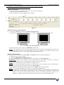
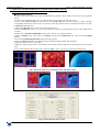
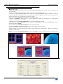
f Double PIP transition:
• Create a frame with 2 black areas with a standard drawing software. The 2 black areas will be receiving the PIP
sources.
• Connect to the EVENTIX the source providing the frame to be stored, and select the source.
• Click on the Logo & Frame tab, then click on the record frame tab: the device displays a white rectangle
corresponding to the frame selection area. If necessary adjust the position and size of the frame selection area with
the position & size functions.
• Adjust the Luma Key level to get to the desired Luma Keying.
• Click on STORE and select 1 or 2 to store the frame into a memory. The memorization starts and will take about
2 minutes.
• Display onto the MAIN & PREVIEW outputs, the 2 sources to be used for the PIPs.
• Select an EFFECT key. Then click on the Effect tab and select Double PIP type. Then select the holding
duration.
• Click on the Background and Inlay button and select a frame.
• Click on TAKE: the frame store is displayed onto the MAIN output together with the 2 PIP.
• Adjust the position & size of each PIP.
• Adjust the mask size & position of each PIP in such manner that the 2 PIP will not be superposed into the black
areas.
• Click on the Background and Inlay button and select inlay = yes if you want to set the PIP in background.
Frame store
Main source
Preview source
The 2 PIP & the frame store are displayed onto the MAIN output
Inlay = no
Inlay = yes
Figure 25: Double PIP.
Figure 26: Double PIP effect window.
PAGE 23
Chapter 3 : OPERATING MODE (continued)
CENTRIX™ & EVENTIX™
3-1. OPERATING WITH THE REMOTE CONTROL SOFTWARE (continued)
3-1-3. OPERATING IN MIXER MODE (continued)
• VIDEO OUTPUT ADJUSTMENTS
Click on the Video tab, and then make the following adjustment:
c Select the output standard (video standard).
d Select the video "output rate".
e Select a level of anti-flicker (flicker adjustment) and a zoom mode (U/Over scan).
• AUDIO ADJUSTMENTS
Click on the Audio tab, and make for each AUDIO output the following adjustment:
c Adjust the master volume.
d Select the mono or stereo audio mode.
e Select an AUDIO input (breakaway mode) or automatic (auto follow mode):
- auto follow = the audio switching follows automatically the video switching.
- breakaway = the selected audio input is permanently diffused.
f For each audio input, adjust the level (audio level) and the balance (audio balance).
IMPORTANT: If the auxiliary audio input (AUX) is used, don't forget to activate it (AUX input = ON).
PAGE 24
CENTRIX™ & EVENTIX™
Chapter 3 : OPERATING MODE (continued)
3-1. OPERATING WITH THE REMOTE CONTROL SOFTWARE (continued)
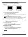
3-1-4. OPERATING IN MATRIX MODE
• SETTINGS
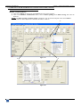
c We recommend resetting the device to its default values (Controls menu > default value) before proceeding.
d Set the CENTRIX™ / EVENTIX™ in MATRIX MODE (Mode menu > matrix).
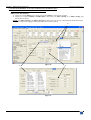
e Click on Settings then click on the Input tab and select the signal type of each source connected to the inputs.
f Click on the Output 1 tab and select the output sync according to your display device.
g Select the output rate mode (Internal rate or follow input...). Then select the frame rate.
h Select one of the output formats.
NOTE: For fixed pixels display device (DMD, LCD, PLASMA…), always select the output format
corresponding to the native resolution of your display device. Thus, the display device will not have to
scale the image and the result will be better.
i Select the type of screen (4/3 or 16/9), according to your wall mounted projection screen shape.
j Click on the Output 2 tab. Then renew the steps g to i for the display device connected to the OUTPUT 2.
e
Figure 27
f
j
e
Figure 28
• INPUT SELECTION
c Pre-select an input with the INPUT SELECT keys of the corresponding OUTPUT. The key starts blinking.
d Press on TAKE to display the pre-selected input onto the output. The transition operates with a fading to black.
NOTE: You can switch simultaneously on the OUTPUT 1 & 2: pre-select an input for the OUTPUT 1, then preselect an input for the OUTPUT 2, finally press the TAKE key.
NOTE: To switch directly from the input select key (without pressing the TAKE key), you should activate the auto
TAKE function (Controls menu > auto TAKE: ON).
PAGE 25
Chapter 3 : OPERATING MODE (continued)
CENTRIX™ & EVENTIX™
3-1. OPERATING WITH THE REMOTE CONTROL SOFTWARE (continued)
3-1-4. OPERATING IN MATRIX MODE (continued)
• DISPLAY DEVICES ADJUSTMENTS
For each OUTPUT:
c Click on the Output tab and select the centering pattern.
d Adjust directly the display device itself, using its controls, to fill the centering pattern in full screen.
Figure 18: Centering pattern.
• IMAGE ADJUSTMENTS
For each input source connected to the device, make the following adjustments:
c Select the source you want to adjust.
d Click on the Image: output 1 or Image: output 2 tab.
e Use the Centering function to automatically position the image in the Centering pattern.
IMPORTANT: For best results, display a full size bright image (no black border) to perform a centering. If
necessary, correct the adjustment with the position & size functions.
NOTE: The centering function is only available for computer sources.
NOTE: In case of same Input/Output resolution, the centering also achieves automatic pixel clock adjustments. It
may be useful, to improve manually the pixel clock and phase.
f If needed, make the others adjustments, available in the IMAGE menu (color, brightness…).
NOTE: To set the image adjustments to the factory settings, use the Preset function.
NOTE: The adjustments are automatically stored in NON-volatile memories. The CENTRIX™ & EVENTIX™ are
provided with 40 NON-volatile image memories. Each of these memories contains the input channel
number, the input and output format parameters and all of the image adjustments (position, size,
brightness...). When the 40 memories are used, each new memorization erases the oldest record.
• VIDEO OUTPUT ADJUSTMENTS
Click on the Video tab, and then make the following adjustment:
c Select the output standard (video standard).
d Select the video "output rate".
e Select a level of anti-flicker (flicker adjustment), and select a zoom mode (U/Over scan).
• AUDIO ADJUSTMENTS
Click on the Audio tab, and make for each AUDIO output the following adjustment:
c Adjust the master volume.
d Select the mono or stereo audio mode.
e Select an AUDIO input (breakaway mode) or automatic (auto follow mode):
- auto follow = the audio switching follows automatically the video switching.
- breakaway = the selected audio input is permanently diffused.
f For each audio input, adjust the level (audio level) and the balance (audio balance).
IMPORTANT: If the auxiliary audio input (AUX) is used, don't forget to activate it with (AUX input = ON).
PAGE 26
CENTRIX™ & EVENTIX™
Chapter 3 : OPERATING MODE (continued)
3-2. OPERATING WITH THE FRONT PANEL OF THE EVENTIX
™
IMPORTANT: The EVENTIX™ can be used in two different modes: the MIXER MODE and the MATRIX MODE.
The MIXER MODE allows switching seamlessly, fading and titling between all the inputs. The
MATRIX MODE allows to display the inputs onto two independents display devices. The default
mode is the MIXER MODE. To set the EVENTIX™ in MATRIX MODE, please refer to the
section: 3-2-2.
3-2-1. OPERATING IN MIXER MODE
• SETTINGS
c We recommend resetting the EVENTIX™ device to its default values, with the LCD menu (CONTROL >
default value > yes) before proceeding.
d Verify the EVENTIX™ is set in MIXER MODE with the LCD menu (MODE > mixer mode).
e Select the input type connected to the inputs with the LCD menu (INPUT > input type).
f Select the output sync according to your display device with the LCD menu (OUTPUT > output sync).
g Select the output rate mode with the LCD menu (OUTPUT > output rate).
h Select one of the output formats with the LCD menu (OUTPUT > output format).
NOTE: For fixed pixels display device (DMD, LCD, PLASMA…), always select the output format corresponding
to the native resolution of your display device. Thus, the display device will not have to scale the image
and the result will be better.
i Select the type of screen (4/3 or 16/9) with the LCD menu (OUTPUT > type of screen > 4/3 or 16/9),
according to your wall mounted projection screen shape.
• INPUT SELECTION
c Pre-select an input with the INPUT SELECT keys. The key starts blinking.
d Select an effect with the EFFECT keys.
e Press on TAKE to do the transition.
Figure 29
NOTE: According to the selected effect the TAKE key may turn ON or blink during the transition. When the
TAKE key is turned ON you should wait for the end of the transition before doing another selection. When
it is blinking, you should press the TAKE key to stop the transition.
PAGE 27
Chapter 3 : OPERATING MODE (continued)
CENTRIX™ & EVENTIX™
3-2. OPERATING WITH THE FRONT PANEL OF THE EVENTIX™ (continued)
3-2-1. OPERATING IN MIXER MODE (continued)
• DISPLAY DEVICES ADJUSTMENTS
c Select the MAIN centering pattern with the LCD menu (OUTPUT > test pattern > main > centering pattern).
d Adjust directly the display device itself, using its controls, to fill the centering pattern in full screen.
Figure 18: Centering pattern.
e Renew the same process to adjust your PREVIEW display device.
NOTE: Now the display devices are identically adjusted, you can also make the image adjustments on the display
device of your choice. When you are in a live display, you can make corrections on the PREVIEW monitor
only, without disturbing the MAIN display device.
• IMAGE ADJUSTMENTS
For each input source connected to the EVENTIX™, make the following adjustments:
c Select the source you want to adjust.
d Select the aspect ratio of your input source with the LCD menu (IMAGE > aspect ratio).
e Use the Centering function with the LCD menu (IMAGE > centering) or with the front panel IMAGE
centering key, to automatically position the image in the Centering pattern.
IMPORTANT: For best results, display a full size bright image (no black border) to perform a centering. If
necessary, correct the position & size with the IMAGE POS. SIZE key or with the LCD menu
(IMAGE > pos settings).
NOTE: The centering function is only available for computer sources.
NOTE: In case of same Input/Output resolution, the centering also achieves automatic pixel clock adjustments. It
may be useful, to improve manually the pixel clock and phase using the LCD menu (IMAGE > optimize
> clock or phase).
f If needed, make the others adjustments, available in the LCD IMAGE menu (color, brightness…).
NOTE: To set the image adjustments to the factory settings, use the Preset function (IMAGE > preset > yes).
NOTE: The adjustments are automatically stored in NON-volatile memories. The EVENTIX™ is provided with 40
NON-volatile image memories. Each of these memories contains the input channel number, the input and
output format parameters and all of the image adjustments (position, size, brightness...). When the 40
memories are used, each new memorization erases the oldest record.
PAGE 28
CENTRIX™ & EVENTIX™
Chapter 3 : OPERATING MODE (continued)
3-2. OPERATING WITH THE FRONT PANEL OF THE EVENTIX™ (continued)
3-2-1. OPERATING IN MIXER MODE (continued)
• EXAMPLES OF TRANSITION
c PIP effect:
The PIP effect allows to insert an image into another one.
• Press the PIP key, then make all the needed adjustments (duration, size, position...) with and validate with
ENTER.
• Press the TAKE key to activate the effect (ACTION 1): the PREVIEW image is inserted into the MAIN image.
NOTE: • You can change the image in the PIP (PREVIEW image) by selecting another input of the PREVIEW
output (ACTION 2): Press the PREVIEW (OUTPUT SELECT) key and select the needed input (the
transition operates with a fading to black).
• You can change the background image (MAIN image) by selecting another input of the MAIN output
(ACTION 3): Press the MAIN (OUTPUT SELECT) key and select the needed input (the transition
operates with a fading to black).
• To remove the PIP effect, press the TAKE key.
See Figure 21: PIP effect. Page 20.
d Title effect (or shadow title):
The TITLE effect allows to display a text onto the MAIN image. For a better readability you also can display a
shadow bar onto your text.
• Create the text to display with the computer connected to the EVENTIX™ thanks to a drawing software like
PowerPoint® (text in white onto a black background).
• Display on the MAIN output the source to titling, then pre-select the source used for create the text: the image
appears on the PREVIEW output.
• Assign the TITLE effect to one of the USER keys: Press one USER key, select title or shadow title with and validate with ENTER, then select the duration with and validate with ENTER.
• Press the TAKE key to activate the effect (ACTION 1): the text is now displayed onto the image of the MAIN
output.
NOTE: You can change the background image (MAIN image) by selecting another input of the MAIN output
(ACTION 2): Press the MAIN output select key and select the needed input (the transition operates with a
fading to black). To remove the TITLE effect, press the TAKE key (ACTION 3).
See Figure 22: Title effect. Page 21.
e Wipe transition:
• Press a USER key, then assign a type of WIPE with the knob and validate with ENTER (for example:
WIPE > hor wipe > from left), then select the duration with and validate with ENTER.
• Press the TAKE key to activate the transition: the PREVIEW image appears onto the MAIN display with a wipe
transition.
See Figure Page 22.
PAGE 29
Chapter 3 : OPERATING MODE (continued)
CENTRIX™ & EVENTIX™
3-2. OPERATING WITH THE FRONT PANEL OF THE EVENTIX™ (continued)
3-2-1. OPERATING IN MIXER MODE (continued)
f Double PIP transition:
• Create a frame with 2 black areas with a standard drawing software. The 2 black areas will be receiving the PIP
source.
• Connect to the EVENTIX the source providing the frame to be stored, and select the source.
• Select the record frame mode (LOGOS/FRAME > record frame > MAIN or PREVIEW): the device displays
a white rectangle corresponding to the frame selection area. If necessary adjust the position and size of the frame
selection area (LOGOS/FRAME > record frame > MAIN or PREVIEW > size or position).
• Adjust the Luma Key level to get to the desired Luma Keying (LOGOS/FRAME > record frame > MAIN or
PREVIEW > Luma Key).
• Store the frame (LOGOS/FRAME > record frame > MAIN or PREVIEW > store > frame 1 or 2). The
memorization starts and will take about 2 minutes.
• Display onto the MAIN & PREVIEW outputs, the 2 sources to be used for the PIPs.
• Select a USER effect key or the PIP effect key. Then with the LCD menu select the holding duration (double PIP
> duration > holding), and select a frame (double PIP > bkgd frame 1 or 2).
• Press on TAKE: the frame store is displayed onto the MAIN output together with the 2 PIP.
• Adjust with the position & size of each PIP (double PIP > position or size).
• Adjust the mask size & position of each PIP in such manner that the 2 PIP will not be superposed into the black
areas (double PIP > mask position or size).
• Select inlay = yes, if you want to set the PIP in background (double PIP > inlay).
See Figure 25: Double PIP. Page 23.
• VIDEO OUTPUT ADJUSTMENTS
c Select the output standard (OUTPUT menu > video output > video standard > NTSC or PAL).
d Select the video "output rate" (OUTPUT menu > video output > output rate >...).
e Select a level of anti-flicker (OUTPUT menu > video output > flicker adj. >...).
f Select the zoom mode (OUTPUT menu > video output > U/Over scan > underscan or overscan).
• AUDIO ADJUSTMENTS
For each AUDIO output, make the following adjustment.
c Adjust the master volume (AUDIO xxxx > master volume).
d Select the mono or stereo audio mode (AUDIO xxxx > audio mode > mono or stereo)
e Select the auto follow or breakaway audio mode (AUDIO > audio source > auto follow or input # x):
- auto follow = the audio switching follows automatically the video switching.
- breakaway = the selected audio input is permanently diffused.
f For each audio input, adjust the level (AUDIO xxxx > audio level) and the balance (AUDIO xxxx > audio
balance).
IMPORTANT: If the auxiliary audio input (AUX) is used, don't forget to activate it with the LCD menu (AUDIO
xxxx > AUX input > ON).
PAGE 30
CENTRIX™ & EVENTIX™
Chapter 3 : OPERATING MODE (continued)
3-2. OPERATING WITH THE FRONT PANEL OF THE EVENTIX™ (continued)
3-2-2. OPERATING IN MATRIX MODE
• SETTINGS
c We recommend resetting the EVENTIX™ device to its default values, with the LCD menu (CONTROL >
default value > yes) before proceeding.
d Set the EVENTIX™ in MATRIX MODE with the LCD menu (MODE > matrix mode).
e Select the input type connected to the inputs with the LCD menu (INPUT > input type).
f Make the following adjustments for the display device connected to the OUTPUT 1:
• Select the output sync according to your display device with the LCD menu (OUTPUT X > output sync).
• Select the output rate mode with the LCD menu (OUTPUT X > output rate).
• Select one of the output formats with the LCD menu (OUTPUT X > output format).
NOTE: For fixed pixels display device (DMD, LCD, PLASMA…), always select the output format
corresponding to the native resolution of your display device. Thus, the display device will not have to
scale the image and the result will be better.
• Select the type of screen (4/3 or 16/9) with the LCD menu (OUTPUT X > type of screen > 4/3 or 16/9),
according to your wall mounted projection screen shape.
g Then renew the adjustments of the step f for the display device connected to the OUTPUT 2.
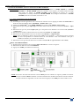
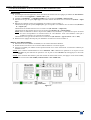
• INPUT SELECTION
c Select an output (OUT 1 or OUT 2) with the OUTPUT SELECT keys.
d Pre-select an input with the INPUT SELECT keys. The key starts blinking.
e Press on TAKE to display the pre-selected input onto the selected output. The transition operates with a fading
to black.
NOTE: You can switch simultaneously on the OUTPUT 1 & 2: do the operations c and d for the OUTPUT 1,
then do the operations c and d for the OUTPUT 2, finally press the TAKE key.
NOTE: To switch directly from the input select key (without pressing the TAKE key), you should activate the auto
TAKE function (CONTROL > auto TAKE: ON).
Figure 30
PAGE 31
Chapter 3 : OPERATING MODE (continued)
CENTRIX™ & EVENTIX™
3-2. OPERATING WITH THE FRONT PANEL OF THE EVENTIX™ (continued)
3-2-2. OPERATING IN MATRIX MODE (continued)
• DISPLAY DEVICES ADJUSTMENTS
For each OUTPUT:
c Select the centering pattern with the LCD menu (OUTPUT X > test pattern > centering pattern).
d Adjust directly the display device itself, using its controls, to fill the centering pattern in full screen.
Figure 18: Centering pattern.
• IMAGE ADJUSTMENTS
For each input source connected to the EVENTIX™, make the following adjustments:
c Select the source you want to adjust.
d Select the aspect ratio of your input source with the LCD menu (IMAGE > aspect ratio).
e Use the Centering function (IMAGE > centering) to automatically position the image in the Centering
pattern.
IMPORTANT: For best results, display a full size bright image (no black border) to perform a centering. If
necessary, correct the position & size with the IMAGE POS. SIZE key or with the LCD menu
(IMAGE > pos settings).
NOTE: The centering function is only available for computer sources.
NOTE: In case of same Input/Output resolution, the centering also achieves automatic pixel clock adjustments. It
may be useful, to improve manually the pixel clock and phase using the LCD menu (IMAGE > optimize
> clock or phase).
f If needed, make the others adjustments, available in the LCD IMAGE menu (color, brightness…).
NOTE: To set the image adjustments to the factory settings, use the Preset function (IMAGE > preset > yes).
NOTE: The adjustments are automatically stored in NON-volatile memories. The EVENTIX™ is provided with 40
NON-volatile image memories. Each of these memories contains the input channel number, the input and
output format parameters and all of the image adjustments (position, size, brightness...). When the 40
memories are used, each new memorization erases the oldest record.
• VIDEO OUTPUT ADJUSTMENTS
c Select the output standard (OUTPUT menu > video output > video standard > NTSC or PAL).
d Select the video "output rate" (OUTPUT menu > video output > output rate >...).
e Select a level of anti-flicker (OUTPUT menu > video output > flicker adj. >...).
f Select the zoom mode (OUTPUT menu > video output > U/Over scan > underscan or overscan).
• AUDIO ADJUSTMENTS
For each AUDIO output, make the following adjustment.
c Adjust the master volume (AUDIO xxxx > master volume).
d Select the mono or stereo audio mode (AUDIO xxxx > audio mode > mono or stereo)
e Select the auto follow or breakaway audio mode (AUDIO > audio source > auto follow or input # x):
- auto follow = the audio switching follows automatically the video switching.
- breakaway = the selected audio input is permanently diffused.
f For each audio input, adjust the level (AUDIO xxxx > audio level) and the balance (AUDIO xxxx > audio
balance).
IMPORTANT: If the auxiliary audio input (AUX) is used, don't forget to activate it with the LCD menu (AUDIO
xxxx > AUX input > ON).
PAGE 32
CENTRIX™ & EVENTIX™
Chapter 3 : OPERATING MODE (continued)
3-3. OPERATING WITH THE REMOTE KEYPAD
IMPORTANT: The CENTRIX™ & EVENTIX™ can be used in two different modes: the MIXER MODE and the
MATRIX MODE. The MIXER MODE allows switching seamlessly, fading and titling between all
the inputs. The MATRIX MODE allows to display the inputs onto two independents display devices.
The default mode is the MIXER MODE. To set the device in MATRIX MODE, please refer to the
section: 3-3-3.
3-3-1. COMMUNICATION SETUP
• CASE OF RS-232 PORT
c Connect the REMOTE KEYPAD to the CENTRIX™ / EVENTIX™ according to your installation (see section 23-1. )
d Then only power ON all the devices.
e Activate the REMOTE KEYPAD RS232 communication port with the LCD of the REMOTE KEYPAD
(CONSOLE > RS232/LAN port > RS232).
• CASE OF LAN PORT
c Connect the REMOTE KEYPAD to the CENTRIX™ / EVENTIX™ with the RS-232 port as indicated above,
then configure the LAN communication port of the CENTRIX™ / EVENTIX™ with the REMOTE KEYPAD
LCD menu (CONTROL > LAN setup).
d Select the LAN communication port of the CENTRIX™ / EVENTIX™ with the LCD menu (CONSOLE >
RS232/LAN port > LAN).
e Connect the LAN port (RJ45 connector) of the CENTRIX™ / EVENTIX™ to your network according to your
installation.
f Connect the LAN port (RJ45 connector) of the REMOTE KEYPAD to your network according to your
installation.
g Then configure the REMOTE KEYPAD LAN communication port with the LCD menu (CONSOLE > LAN
setup).
h Activate the REMOTE KEYPAD LAN communication port with the LCD menu (CONSOLE > RS232/LAN
port > LAN).
NOTE: If the communication doesn't work (CENTRIX™ only), you need to reconnect the RS-232 communication
port to your Remote Keypad, and restart the device. The device will also automatically detect and activate
the RS232 communication port.
3-3-2. OPERATING IN MIXER MODE
• SETTINGS
c We recommend resetting the CENTRIX™ / EVENTIX™ device to its default values, with the LCD menu
(CONTROL > default value > yes) before proceeding.
d Verify the CENTRIX™ / EVENTIX™ is set in MIXER MODE with the LCD menu (MODE > mixer mode).
e Select the input type connected to the inputs with the LCD menu (INPUT > input type).
f Select the output sync. type which corresponds to your display device with the LCD menu (OUTPUT > output
sync).
g Select the output rate mode with the LCD menu (OUTPUT > output rate).
h Select one of the output formats with the LCD menu (OUTPUT > output format).
NOTE: For fixed pixels display device (DMD, LCD, PLASMA…), always select the output format corresponding
to the native resolution of your display device. Thus, the display device will not have to scale the image
and the result will be better.
i Select the type of screen (4/3 or 16/9) with the LCD menu (OUTPUT > type of screen > 4/3 or 16/9),
according to your wall mounted projection screen shape.
PAGE 33
Chapter 3 : OPERATING MODE (continued)
CENTRIX™ & EVENTIX™
3-3. OPERATING WITH THE REMOTE KEYPAD (continued)
3-3-2. OPERATING IN MIXER MODE (continued)
• INPUT SELECTION
c Pre-select an input with the INPUT SELECT keys. The key starts blinking.
d Select an effect with the EFFECT keys.
e Press on TAKE or move manually the T-BAR to do the transition.
Figure 31
NOTE: According to the selected effect the TAKE key may turn ON or blink during the transition. When the
TAKE key is turned ON you should wait for the end of the transition before doing another selection. When
it is blinking, you should press the TAKE key to stop the transition.
• DISPLAY DEVICES ADJUSTMENTS
c Select the MAIN centering pattern with the LCD menu (OUTPUT > test pattern > main > centering pattern).
d Adjust directly the display device itself, using its controls, to fill the centering pattern in full screen.
See Figure 18: Centering pattern. Page 18.
e Renew the same process to adjust your PREVIEW display device.
NOTE: Now the display devices are identically adjusted, you can also make the image adjustments on the display
device of your choice. When you are in a live display, you can make corrections on the PREVIEW monitor
only, without disturbing the MAIN display device.
• IMAGE ADJUSTMENTS
For each input source connected to the CENTRIX™ / EVENTIX™ make the following adjustments:
c Select the source you want to adjust.
d Select the aspect ratio of your input source with the LCD menu (IMAGE > aspect ratio).
e Use the Centering function with the LCD menu (IMAGE > centering) or with the front panel IMAGE
centering key to automatically position the image in the Centering pattern.
IMPORTANT: For best results, display a full size bright image (no black border) to perform a centering. If
necessary, correct the adjustment the position & size with the IMAGE POS/SIZE key or with the
LCD menu (IMAGE > pos settings).
NOTE: The centering function is only available for computer sources.
NOTE: In case of same Input/Output resolution, the centering also achieves automatic pixel clock adjustments. It
may be useful, to improve manually the pixel clock and phase using the LCD menu (IMAGE > optimize
> clock or phase).
f If needed, make the others adjustments, available in the LCD IMAGE menu (color, brightness…).
NOTE: To set the image adjustments to the factory settings, use the Preset function (IMAGE > preset > yes).
NOTE: The adjustments are automatically stored in NON-volatile memories. The CENTRIX™ & EVENTIX™ are
provided with 40 NON-volatile image memories. Each of these memories contains the input channel
number, the input and output format parameters and all of the image adjustments (position, size,
brightness...). When the 40 memories are used, each new memorization erases the oldest record.
PAGE 34
CENTRIX™ & EVENTIX™
Chapter 3 : OPERATING MODE (continued)
3-3. OPERATING WITH THE REMOTE KEYPAD (continued)
3-3-2. OPERATING IN MIXER MODE (continued)
• EXAMPLES OF TRANSITION
c PIP effect:
The PIP effect allows to insert an image into another one.
• Press the PIP key, then make all the needed adjustments (duration, size, position...) with and validate with
ENTER.
• Press the TAKE key to activate the effect (ACTION 1): the PREVIEW image is inserted into the MAIN image.
NOTE: • You can change the image in the PIP (PREVIEW image) by selecting another input of the PREVIEW
output (ACTION 2): Press the PREVIEW (OUTPUT SELECT) key and select the needed input (the
transition operates with a fading to black)
• You can change the background image (MAIN image) by selecting another input of the MAIN output
(ACTION 3): Press the MAIN (OUTPUT SELECT) key and select the needed input (the transition
operates with a fading to black).
• To remove the PIP effect, press the TAKE key.
See Figure 21: PIP effect. Page 20.
d Title effect (or shadow title):
The TITLE effect allows to display a text onto the MAIN image. For a better readability you also can display a
shadow bar onto your text.
• Create the text to display with the computer connected to the CENTRIX™ / EVENTIX™ thanks to a drawing
software like PowerPoint® (text in white onto a black background).
• Display on the MAIN output the source to titling, then pre-select the source used for create the text: the image
appears on the PREVIEW output.
• Assign the TITLE effect to one of the USER keys: Press one USER key, select title or shadow title with and validate with ENTER, then select the duration with and validate with ENTER.
• Press the TAKE key to activate the effect (ACTION 1): the text is now displayed onto the image of the MAIN
output.
NOTE: You can change the background image (MAIN image) by selecting another input of the MAIN output
(ACTION 2): Press the MAIN output select key and select the needed input (the transition operates with a
fading to black). To remove the TITLE effect, press the TAKE key (ACTION 3).
See Figure 22: Title effect. Page 21.
e Wipe transition:
• Assign a WIPE to one of the USER keys: Press one USER key, select a WIPE with the knob and validate
with ENTER (for example: hor wipe > from left), then select the duration with and validate with ENTER.
• Press the TAKE key to activate the transition: the PREVIEW image appears onto the MAIN display with a wipe
transition.
See Figures Page 22.
• VIDEO OUTPUT ADJUSTMENTS
c Select the output standard (OUTPUT menu > video output > video standard > NTSC or PAL).
d Select the video "output rate" (OUTPUT menu > video output > output rate >...).
f Select the zoom mode (OUTPUT menu > video output > U/Over scan > underscan or overscan).
e Select a level of anti-flicker (OUTPUT menu > video output > flicker adj. >...).
• AUDIO ADJUSTMENTS
For each AUDIO output, make the following adjustment.
c Adjust the master volume (AUDIO xxxx > master volume).
d Select the mono or stereo audio mode (AUDIO xxxx > audio mode > mono or stereo)
e Select the auto follow or breakaway audio mode (AUDIO > audio source > auto follow or input # x):
- auto follow = the audio switching follows automatically the video switching.
- breakaway = the selected audio input is permanently diffused.
f For each audio input, adjust the level (AUDIO xxxx > audio level) and the balance (AUDIO xxxx > audio
balance).
IMPORTANT: If the auxiliary audio input (AUX) is used, don't forget to activate it with the LCD menu (AUDIO
xxxx > AUX input > ON).
PAGE 35
Chapter 3 : OPERATING MODE (continued)
CENTRIX™ & EVENTIX™
3-3. OPERATING WITH THE REMOTE KEYPAD (continued)
3-3-3. OPERATING IN MATRIX MODE
• SETTINGS
c We recommend resetting the CENTRIX™ / EVENTIX™ device to its default values, with the LCD menu
(CONTROL > default value > yes) before proceeding.
d Set the CENTRIX™ / EVENTIX™ in MATRIX MODE with the LCD menu (MODE > matrix mode).
e Select the input type connected to the INPUTS (# 1 to # 8) with the LCD menu (INPUT > input type).
f Make the following adjustments for the display device connected to the OUTPUT 1:
• Select the output sync. type which corresponds to the display device with the LCD menu (OUTPUT X>
output sync).
• Select the output rate mode with the LCD menu (OUTPUT X > output rate).
• Select one of the output formats with the LCD menu (OUTPUT X > output format).
NOTE: For fixed pixels display device (DMD, LCD, PLASMA…), always select the output format
corresponding to the native resolution of your display device. Thus, the display device will not have to
scale the image and the result will be better.
• Select the type of screen (4/3 or 16/9) with the LCD menu (OUTPUT X > type of screen > 4/3 or 16/9),
according to your wall mounted projection screen shape.
g Then renew the adjustments of the step f for the display device connected to the OUTPUT 2.
• INPUT SELECTION
c Select an output (OUT 1 or OUT 2) with the OUTPUT SELECT keys.
d Pre-select an input with the INPUT SELECT keys. The key starts blinking.
e Press on TAKE or move manually the T-BAR to display the pre-selected input onto the selected output. The
transition operates with a fading to black.
NOTE: You can switch simultaneously on the OUTPUT 1 & 2: do the operations c and d for the OUTPUT 1,
then do the operations c and d for the OUTPUT 2, finally press the TAKE key.
Figure 32
• DISPLAY DEVICES ADJUSTMENTS
For each OUTPUT:
c Select the centering pattern (OUTPUT X > test pattern > centering pattern).
d Adjust directly the display device itself, using its controls, to fill the centering pattern in full screen.
See Figure 18: Centering pattern. Page 18.
PAGE 36
CENTRIX™ & EVENTIX™
Chapter 3 : OPERATING MODE (continued)
3-3. OPERATING WITH THE REMOTE KEYPAD (continued)
3-3-3. OPERATING IN MATRIX MODE (continued)
• IMAGE ADJUSTMENTS
For each input source connected to the CENTRIX™ / EVENTIX™ make the following adjustments:
c Select the source you want to adjust.
d Select the aspect ratio of your input source with the LCD menu (IMAGE > aspect ratio).
e Use the Centering function (IMAGE > centering) to automatically position the image in the Centering
pattern.
IMPORTANT: For best results, display a full size bright image (no black border) to perform a centering. If
necessary, correct the adjustment the position & size with the IMAGE POS/SIZE key or with the
LCD menu (IMAGE > pos settings).
NOTE: The centering function is only available for computer sources.
NOTE: In case of same Input/Output resolution, the centering also achieves automatic pixel clock adjustments. It
may be useful, to improve manually the pixel clock and phase using the LCD menu (IMAGE > optimize
> clock or phase).
f If needed, make the others adjustments, available in the LCD IMAGE menu (color, brightness…).
NOTE: To set the image adjustments to the factory settings, use the Preset function (IMAGE > preset > yes).
NOTE: The adjustments are automatically stored in NON-volatile memories. The CENTRIX™ / EVENTIX™ are
provided with 40 NON-volatile image memories. Each of these memories contains the input channel
number, the input and output format parameters and all of the image adjustments (position, size,
brightness...). When the 40 memories are used, each new memorization erases the oldest record.
• VIDEO OUTPUT ADJUSTMENTS
c Select the output standard (OUTPUT menu > video output > video standard > NTSC or PAL).
d Select the video "output rate" (OUTPUT menu > video output > output rate >...).
e Select a level of anti-flicker (OUTPUT menu > video output > flicker adj. >...).
f Select the zoom mode (OUTPUT menu > video output > U/Over scan > underscan or overscan).
• AUDIO ADJUSTMENTS
For each AUDIO output, make the following adjustment.
c Adjust the master volume (AUDIO xxxx > master volume).
d Select the mono or stereo audio mode (AUDIO xxxx > audio mode > mono or stereo)
e Select the auto follow or breakaway audio mode (AUDIO > audio source > auto follow or input # x):
- auto follow = the audio switching follows automatically the video switching.
- breakaway = the selected audio input is permanently diffused.
f For each audio input, adjust the level (AUDIO xxxx > audio level) and the balance (AUDIO xxxx > audio
balance).
IMPORTANT: If the auxiliary audio input (AUX) is used, don't forget to activate it with the LCD menu (AUDIO
xxxx > AUX input > ON).
PAGE 37
CENTRIX™ & EVENTIX™
Chapter 4 : UPDATING
The CENTRIX™ / EVENTIX™ can be update thanks a COMPUTER (PC) via its REMOTE (RS-232) connector.
4-1. CONNECTIONS
c Connect the "REMOTE CONTROL RS-232" connector of the device to the SERIAL port of your COMPUTER
with a DB9 M/F straight cable.
d Connect the device to an AC power outlet.
e Switch OFF the device (rear panel switch = O).
Figure 33: Updating.
4-2. UPDATE INSTRUCTIONS
c
d
e
f
Open the file "iX updater" (in start/Program/ANALOG WAY/iX8022).
Click on "START" on the SOFTWARE.
Switch ON the device. The POWER LED blinking slowly and the update will start.
When the software displays "Program operation completed", SWITCH OFF and ON the device with the rear panel
switch.
g Click on the "QUIT" button to close the update software.
NOTE: Your CENTRIX™ / EVENTIX™ is now ready to work.
NOTE: The updater files are available on our web site: http://www.analogway.com
PAGE 38
CENTRIX™ & EVENTIX™
Chapter 5 : USING FRAME STORE AND LOGO INSERTION
5-1. USING LOGO INSERTION WITH THE REMOTE CONTROL SOFTWARE
This function allows storing up to 8 logos in order to incrust them into the displayed image (up to 2 logos at a same time).
IMPORTANT: The output format used when displaying logo should be the same that the output format used during the
logo storing.
5-1-1. HOW TO STORE A LOGO
c Click on the Logo & Frame main tab to record the logo from the MAIN output or click on the Logo & Frame
preview tab to record the logo from the PREVIEW output.
d Then click on the Record logo tab: the device displays a white rectangle corresponding to the logo selection area
onto the output. Then adjust the position and size of the logo area with the position functions.
NOTE: The logo area is limited to an eighth (1/8) of the displayed area.
e If necessary, adjust the luma key level. This function allows to "erasing" the darkest portions of the logo selection
area in order to make special logo contour. Otherwise set the luma key level to zero.
NOTE: You can change the color of the "erased portions" of the logo with the background color function.
f Click on STORE to store the logo into a memory. The memorization of the logo starts and will take about few
seconds.
NOTE: Renew the steps c to f to store another logo (up to 8).
5-1-2. HOW TO ASSIGN A LOGO
NOTE: You can assign the stored logos to one or many of the 8 inputs (up to 2 logos by inputs).
g In the assignment table, assign for each input the needed logos.
NOTE: To remove a logo of an input, select none in the corresponding window.
5-1-3. HOW TO DISPLAY OFF or ON A LOGO
h To display OFF or ON the assigned logos of an input, click on the display button of the corresponding input to
change the status (ON or OFF).
NOTE: When displaying ON or OFF a logo, this one appears/disappears with a fade effect. You can adjust the
duration of the fade effect with the Frame fade duration function of the Control menu.
5-1-4. HOW TO ADJUST THE LOGO POSITION
i Select the input of the logo to adjust (with the INPUT SELECTION buttons).
j Click on the logo to adjust, and then click on the use tab of the Logo & frame window. Then adjust the logo
position with the H &V position functions.
NOTE: When you are using 2 logos by input, make sure to not superpose a logo onto an other one. In case of
superposition, the logo areas will appear colored.
g
h
c
d
e
f
Figure 34
PAGE 39
Chapter 5 : USING FRAME STORE AND LOGO INSERTION (continued)
CENTRIX™ & EVENTIX™
5-1. USING LOGO INSERTION WITH THE REMOTE CONTROL SOFTWARE (continued)
5-1-5. EXAMPLE OF LOGO INSERTION
Figure 35
Logo source
(white border = logo area)
Video source
Video source with inserted logo.
(logo made with luma key)
5-2. USING FRAME STORE WITH THE REMOTE CONTROL SOFTWARE
This function allows memorizing up to 3 frames (images) in order to display it at any time during the show.
IMPORTANT: The output format used when displaying the frame should be the same that the output format used during
the frame storing.
5-2-1. HOW TO STORE A FRAME
c Click on the Logo & Frame main tab to record the frame from the MAIN output or click on the Logo & Frame
preview tab to record the frame from the PREVIEW output.
d Then click on the Record frame tab: the device displays a white rectangle corresponding to the frame selection area
onto the output. If necessary adjust the position and size of the frame area with the position & size functions.
e Adjust the Luma Key level to get to the desired Luma Keying.
f Click on STORE to store the frame into a memory. The memorization starts and will take about 2 minutes.
NOTE: For motion picture, you can use the FREEZE function, before doing the memorization.
5-2-2. HOW TO ASSIGN A FRAME
g In the assignment table, assign a frame to the needed inputs.
NOTE: To remove the frame of an input, select none in the corresponding window.
5-2-3. HOW TO DISPLAY ON or OFF the FRAME
h To display ON or OFF the assigned frame of an input, click on the display button of the corresponding input to
change the status (ON or OFF). The frame appears onto the output, instead of the source connected to this input.
NOTE: When displaying ON or OFF a frame, this one appears/disappears with a fade effect. You can adjust the
duration of the fade effect with the Frame fade duration function of the Control menu.
g
h
c
d
f
Figure 36
PAGE 40
CENTRIX™ & EVENTIX™
Chapter 5 : USING FRAME STORE AND LOGO INSERTION (continued)
5-3. USING LOGO INSERTION WITH THE REMOTE KEYPAD OR EVENTIX™
This function allows storing up to 8 logos in order to incrust them into the displayed image (up to 2 logos at a same time).
IMPORTANT: The output format used when displaying logo should be the same that the output format used during the
logo storing.
5-3-1. HOW TO STORE A LOGO
c Select the source of the logo to be stored (with the INPUT SELECTION buttons).
d Select the MAIN or PREVIEW record logo mode (LOGOS/FRAME > record logo > MAIN or PREVIEW):
the device displays a white rectangle corresponding to the logo selection area onto the output. Then adjust the
position and size of the logo selection area with the LCD record logo menu functions.
NOTE: The logo area is limited to an eighth (1/8) of the displayed area.
e If necessary, adjust the luma key level (LOGOS/FRAME > record logo > MAIN or PREVIEW > luma key
level). This function allows to "erasing" the darkest portions of the logo selection area in order to make special logo
contour. Otherwise set the luma key level to zero.
NOTE: You can change the color of the "erased portions" of the logo (LOGOS/FRAME > record logo > back.
color).
f Store the logo into a memory (LOGOS/FRAME > record logo > MAIN or PREVIEW > store > empty or logo
x). The memorization of the logo starts and will take about few seconds.
NOTE: Renew the steps c to f to store another logo (up to 8).
5-3-2. HOW TO ASSIGN A LOGO
NOTE: You can assign the stored logos to one or many of the 8 inputs (up to 2 logos by inputs).
g In the assignment menu (LOGOS/FRAME > use logo/frame > assignment), select the displayed input (MAIN or
PREVIEW) that you want to assign a logo, then select an index (1 or 2) and finally select the needed logo.
NOTE: To remove a logo from an input, select the corresponding input & index and select none.
NOTE: To assign the same logo to all inputs select ALL (instead MAIN or PREVIEW).
h With the INPUT SELECTION buttons, display successively all your inputs to verify your logo assignment. If no
logo appears on an input: verify that the LCD display function of the corresponding input is not set to the OFF
position. In this case press ENTER to set it to the ON position (See how to display OFF or ON a logo).
5-3-3. HOW TO DISPLAY OFF or ON A LOGO
i To display OFF or ON the assigned logos of an input, select the MAIN or PREVIEW displayed input in the display
menu (LOGOS/FRAME > use logo/frame > display > MAIN or PREVIEW) and press ENTER to change the
status (ON or OFF).
NOTE: When displaying ON or OFF a logo, this one appears/disappears with a fade effect. You can adjust the
duration of this fade effect (LOGOS/FRAME > use logo/frame > fade duration).
5-3-4. HOW TO ADJUST THE LOGO POSITION
j Press the MAIN / OUTPUT 1 key or the PREVIEW / OUTPUT 2 key.
k Press the LOGO position key. Then adjust the logo position with the H &V position functions.
NOTE: When you are using 2 logos by input, make sure to not superpose a logo onto an other one. In case of
superposition, the logo areas will appear colored.
5-3-5. EXAMPLE OF LOGO INSERTION
Figure 37
Logo source
(white border = logo area)
Video source
Video source with inserted logo.
(logo made with luma key)
PAGE 41
Chapter 5 : USING FRAME STORE AND LOGO INSERTION (continued)
5-4. USING FRAME STORE WITH THE REMOTE KEYPAD OR THE EVENTIX
CENTRIX™ & EVENTIX™
™
This function allows memorizing up to 2 frames (images) in order to display it at any time during the show.
IMPORTANT: The output format used when displaying the frame should be the same that the output format used during
the frame storing.
5-4-1. HOW TO STORE A FRAME
c Select the source of the frame to be stored (with the INPUT SELECTION buttons).
d Select the MAIN or PREVIEW record frame mode (LOGOS/FRAME > record frame > MAIN or
PREVIEW): the device displays a white rectangle corresponding to the frame selection area. If necessary adjust the
position and size of the frame selection area (LOGOS/FRAME > record frame > MAIN or PREVIEW > size or
position).
e Adjust the Luma Key level to get to the desired Luma Keying (LOGOS/FRAME > record frame > MAIN or
PREVIEW > Luma Key).
f Store the frame (LOGOS/FRAME > record frame > MAIN or PREVIEW > store). The memorization starts and
will take about 2 minutes.
NOTE: For motion picture, you can use the FREEZE function, before doing the memorization.
5-4-2. HOW TO ASSIGN A FRAME
g In the assignment menu (LOGOS/FRAME > use logo/frame > assignment), select the displayed input (MAIN or
PREVIEW) that you want to assign the frame, then select frame index select a frame.
NOTE: To remove the frame from an input, select the corresponding input & index and select none.
5-4-3. HOW TO DISPLAY ON or OFF the FRAME
h To display ON the frame, select the input corresponding to the frame with the INPUT SELECTION buttons. The
FRAME appears onto the output, instead of the source connected to this input.
NOTE: If the frame doesn't appear: verify that the display function of the displayed input is not set in the OFF
position (LOGOS/FRAME > use logo/frame > display). In this case, presses ENTER to set it in the ON
position.
i To display OFF the frame, set the display function in OFF position (LOGOS/FRAME > use logo/frame > display
> MAIN or PREVIEW > OFF).
PAGE 42
CENTRIX™ & EVENTIX™
Chapter 6 : EVENTIX™ & REMOTE KEYPAD LCD SCREEN DESCRIPTION
6-1. INTRODUCTION
The LCD screen is composed of 2 modes: the STATUS MODE and the CONTROL MODE.
• The STATUS MODE indicates the input and the output status.
• The CONTROL MODE allows selecting and adjusting the parameters.
6-2. LCD CONTROL BUTTONS
The LCD screen is controlled by 3 buttons:
knob:
To scroll thru the different menus.
EXIT MENU button:
• From the STATUS MODE, press on this button to display the CONTROL MODE.
• From the CONTROL MODE, press on this button to:
- return to the previous menu without safeguarding the item.
- return to the STATUS MODE (press several times).
ENTER button:
• From the STATUS MODE, press on this button to display the CONTROL MODE.
• From the CONTROL MODE, press on this button to confirm a selected item.
6-3. STATUS MODE
When switching ON the device, the LCD screen shows the product's name and status as follows:
PRODUCT NAME
PRODUCT MODEL
e
f
g
REMOTE KEYPAD
RK8022
V_._
OUTPUT
internal rate
XGA
XGA
60Hz
MAIN = 3
40.6K / 60Hz
PREVIEW = 5
SXGA
64K / 60Hz
DEVICE STATUS MENU
c
d
OUTPUT STATUS MENU
SELECTION STATUS MENU
PRE-SELECTION STATUS MENU
c DEVICE VERSION
d OUTPUT FORMAT
e OUTPUT RATE
f SELECTED INPUT
g PRE-SELECTED INPUT
PAGE 43
Chapter 6 : EVENTIX™ & REMOTE KEYPAD LCD SCREEN DESCRIPTION (continued)
CENTRIX™ & EVENTIX™
6-4. CONTROL MODE
6-4-1. CONFIGURATION IN MIXER MODE
1 MODE
1 mixer mode
2 matrix mode
2 INPUT
1 input type
1 #1 Comp. HV/C
2 #2 Comp. HV/C
3 #3 Comp. HV/C
4 #4 Comp. HV/C
5 #5 Comp. HV/C
6 #6 Comp. HV/C
7 #7 Comp. HV/C
8 #8 Comp. HV/C
9 All inputs
2 used input
3 H. sync. load
1 SDTV Composite
2 SDTV S.VIDEO
3 SDTV YUV
4 SDTV RGBS TTL
5 SDTV RGB SOG
6 SDTV RGBS ana.
7 SDTV SDI
8 Computer SOG
9 Computer HV/C
10 Computer DVI
11 HDTV
1 NTSC/PAL/SECAM
2 NTSC
3 PAL
4 SECAM
5 B&W 50/60Hz
4 VCR mode
5 synchronized
6 input status
3 OUTPUT
1 output format
1 WVGA:852x480
2 SVGA:800x600
3 XGA:1024x768
4 SXGA:1280x1K
5 SXGA+:1400x1K
6 D-ILA 4/3
7 D-ILA 16/9
8 HDTV 720p
2 output rate
1 internal 50 Hz
2 internal 60 Hz
2 internal 72 Hz
4 internal 75 Hz
5 follow…
3 output sync
4 type of screen
5 test pattern
6 video output
7 output status
4 IMAGE
image
main preview
output sync
main preview
output screen
4/3
16/9
test pattern
main preview
1 video standard
2 output rate
3 flicker adj.
4 U/overscan
5 pos. setting
6 input stab.
7 color tracking.
1 follow input#1
2 follow input#2
………
8 follow input#8
H&V COMP SOG
H&V COMP SOG
1 no pattern
2 centering
3 color bar
4 V. grey scale
5 grid
6 softedge
7 burst
8 H. grey scale
1 centering
2 pos settings
3 zoom settings
4 aspect ratio
IF VIDEO INPUT
5 brightness
6 contrast
7 color
8 hue
9 under/over
10 sharpness
11 preset
5 LOGOS/FRAME
1 use logo/frame
use logo/frame
main preview
1 4/3 standard
2 16/9 letterbox
3 WS anamorphic
4 zoom
1 zoom size
2 zoom position
IF COMPUTER INPUT
5 processing
6 black level
7 color
8 optimize
9 preset
1 Red level
2 Green level
3 Bleu level
1 clock
2 phase
1 display
2 assignment
frame index
F1
1 none
…….
3 frame 2
L8
no
1 none
…….
2 V.position
3 fade duration
4 transparence
2 record logo
3 record frame
4 erase
PAGE 44
record logo
main preview
record frame
main preview
1 erase frame
………
12 erase all
1 size
2 position
3 luma key level
4 back. color
5 store
1 size
2 position
3 luma key level
4 back. color
5 store
logo index1
logo index2
9 logo 8
1 logo 1 (L1)
…
8 logo 8 (L8)
1 frame 1 (F1)
2 frame 2 (F2)
1 H.position
2 H.position
CENTRIX™ & EVENTIX™
Chapter 6 : EVENTIX™ & REMOTE KEYPAD LCD SCREEN DESCRIPTION (continued)
6-4. CONTROL MODE (continued)
6-4-1. CONFIGURATION IN MIXER MODE (continued)
6 EFFECT
1 current effect
2 USER 1 key
3 USER 2 key
4 USER 3 key
5 USER 4 key
1 cut
2 fading
1s 3s 5s custom
1 duration
2 effect opening
3 effect closing
4 shadow title
1 duration
2 size
3 position
4 intensity
5 effect opening
6 effect closing
holding
3s
5s
custom
effect duration
======= xxs
5 Hor. WIPE
1 from left
2 from right
3 to center
4 from center
holding
3s
5s
custom
effect duration
======= xxs
6 Vert. WIPE
1 up
2 down
3 to center
4 from center
holding
3s
5s
custom
effect duration
======= xxs
7 Square WIPE
1 to center
2 from center
8 Slide
1 from left
2 from right
3 to center
4 from center
holding
3s
5s
custom
effect duration
======= xxs
9 PIP
1 duration
2 size
3 position
4 mask size
5 mask position
6 border
7 effect opening
8 effect closing
holding
3s
5s
custom
effect duration
======= xxs
10 Double PIP
7 AUDIO MAIN
8 AUDIO PRELIST
1 master volume
2 audio mode
1 mono
2 stereo
3 audio source
1 auto follow
2 input # 1
…..
9 input # 8
4 audio level
5 audio balance
6 AUX input OFF
7 mute
ON
9 CONTROL
1 versions
2 auto TAKE
3 RS232/LAN port
1 UDP
2 TCP
5 transition
1 fade color
2 fade frame
3 clean cut
7 2:2 pull down
auto
8 tally
1 tally 1
…
4 tally status
9 key brightness
1
10 CONSOLE
off
10 key locking
1 menus
2 input
3 all
4 auto lock
11 erase memories
12 languages
13 demo mode
14 default value
no
yes
no
yes
1 RS232/LAN port
comm port select
RS232 LAN
2 LAN setup
1 UDP
2 TCP
3 key locking
5 RK8022 version
1 menus
2 input
3 all
4 auto lock
6 default value
no
4 key brightness
1
comm port select
RS232 LAN
4 LAN setup
6 sync-loss
effect duration
======= xxs
3 title
yes
1 duration
2 size
3 position
4 mask size
5 mask position
6 inlay: yes
7 bkgd frame: 1
1 Eventix addr.
2 remote addr.
3 gateway addr.
4 Eventix port
5 remote port
6 netmask
7 default setup
1 without
2 shadow
1 size
2 intensity
3 smooth
1 size
4 edge
1 size
2 color
holding
3s
5s
custom
effect duration
======= xxs
select address
xxx.xxx.xxx.xxx
select port
xxxxx
select netmask
xxx.xxx.xxx.xxx
1 input # 1
2 input # 2
……………
1 RK addr.
2 remote addr.
3 gateway addr.
4 RK port
5 remote port
6 netmask
7 default setup
select address
xxx.xxx.xxx.xxx
select port
xxxxx
select netmask
xxx.xxx.xxx.xxx
this menu is available on the REMOTE KEYPAD only.
PAGE 45
Chapter 6 : EVENTIX™ & REMOTE KEYPAD LCD SCREEN DESCRIPTION (continued)
CENTRIX™ & EVENTIX™
6-4. CONTROL MODE (continued)
6-4-2. CONFIGURATION IN MATRIX MODE
1 MODE
1 mixer mode
2 matrix mode
2 INPUT
1 input type
1 #1 Comp. HV/C
2 #2 Comp. HV/C
3 #3 Comp. HV/C
4 #4 Comp. HV/C
5 #5 Comp. HV/C
6 #6 Comp. HV/C
7 #7 Comp. HV/C
8 #8 Comp. HV/C
9 All inputs
2 used input
3 H. sync. load
1 SDTV Composite
2 SDTV S.VIDEO
3 SDTV YUV
4 SDTV RGBS TTL
5 SDTV RGB SOG
6 SDTV RGBS ana.
7 SDTV SDI
8 Computer SOG
9 Computer HV/C
10 Computer DVI
11 HDTV
1 NTSC/PAL/SECAM
2 NTSC
3 PAL
4 SECAM
5 B&W 50/60Hz
4 VCR mode
5 synchronized
6 input status
3 OUTPUT 1
1 output format
1 WVGA:852x480
2 SVGA:800x600
3 XGA:1024x768
4 SXGA:1280x1K
5 SXGA+:1400x1K
6 D-ILA 4/3
7 D-ILA 16/9
8 HDTV 720p
2 output rate
1 internal 50 Hz
2 internal 60 Hz
2 internal 72 Hz
4 internal 75 Hz
4 OUTPUT 2
5 follow…
3 output# sync
4 type of screen
5 test pattern
6 video output
7 output status
5 IMAGE
image
out 1 out 2
output sync
out 1 out 2
output screen
4/3
16/9
test pattern
out 1 out 2
1 video standard
2 output rate
3 flicker adj.
4 U/overscan
5 pos. setting
6 input stab.
7 color tracking.
1 follow input#1
2 follow input#2
………
8 follow input#8
H&V COMP SOG
H&V COMP SOG
1 no pattern
2 centering
3 color bar
4 V. grey scale
5 grid
6 softedge
7 burst
8 H. grey scale
1 centering
2 pos. settings
3 zoom settings
4 aspect ratio
IF VIDEO INPUT
5 brightness
6 contrast
7 color
8 hue
9 under/over
10 sharpness
11 preset
6 LOGOS/FRAME
1 use logo/frame
use logo/frame
out 1 out 2
1 4/3 standard
2 16/9 letterbox
3 WS anamorphic
4 zoom
IF COMPUTER INPUT
5 processing
6 black level
7 color
8 optimize
9 preset
3 fade duration
4 transparence
3 record frame
4 erase
PAGE 46
record logo
out 1 out 2
record frame
out 1 out 2
1 erase frame 1
………
12 erase all
1 Red level
2 Green level
3 Bleu level
1 clock
2 phase
1 display
2 assignment
2 record logo
1 zoom size
2 zoom position
1 size
2 position
3 luma key level
4 back. color
5 store
1 size
2 position
3 luma key level
4 back. color
5 store
frame index
logo index1
logo index2
1 logo 1 (L1)
…
8 logo 8 (L8)
1 frame 1 (F1)
2 frame 2 (F2)
F1
1 none
…….
3 frame 2 (F2)
L8
no
1 none
…….
10 logo 8 (L8)
1 H.position
2 V.position
CENTRIX™ & EVENTIX™
Chapter 6 : EVENTIX™ & REMOTE KEYPAD LCD SCREEN DESCRIPTION (continued)
6-4. CONTROL MODE (continued)
6-4-2. CONFIGURATION IN MATRIX MODE (continued)
7 AUDIO OUT1
8 AUDIO OUT2
1 master volume
2 audio mode
1 mono
2 stereo
3 audio source
1 auto follow
2 input # 1
…..
9 input # 8
4 audio level
5 audio balance
6 AUX input OFF
7 mute
ON
1 versions
9 CONTROL
2 auto TAKE
3 RS232/LAN port
4 LAN setup
comm port select
RS232 LAN
1 UDP
2 TCP
1 Eventix addr.
2 remote addr.
3 gateway addr.
4 Eventix port
5 remote port
select address
xxx.xxx.xxx.xxx
select port
xxxxx
6 netmask
select netmask
xxx.xxx.xxx.xxx
7 default setup
transition
out 1 out 2
5 transition
6 sync-loss
2 fade frame
7 2:2 pull down
auto
8 tally
1 tally 1
…
4 tally status
9 key brightness
1 fade color
off
10 key locking
1 menus
2 input
3 all
4 auto lock
11 erase memories
no
yes
no
yes
3 clean cut
1 red level
2 green level
3 bleu level
fade frame
out 1 out 2
1 frame 1
2 frame 2
1 input # 1
2 input # 2
……………
12 languages
13 default value
1
10 CONSOLE
1 RS232/LAN port
2 LAN setup
comm port select
RS232 LAN
1 UDP
2 TCP
1 RK addr.
2 remote addr.
3 gateway addr.
4 RK port
5 remote port
6 netmask
7 default setup
3 key locking
4 key brightness
select address
xxx.xxx.xxx.xxx
select port
xxxxx
select netmask
xxx.xxx.xxx.xxx
1 menus
2 input
3 all
4 auto lock
5 RK8022 version
6 default value
1
no
yes
this menu is available on the REMOTE KEYPAD only.
PAGE 47
Chapter 6 : EVENTIX™ & REMOTE KEYPAD LCD SCREEN DESCRIPTION (continued)
CENTRIX™ & EVENTIX™
6-5. LCD FUNCTIONS DESCRIPTION
1[MODE] + ENTER.
Select a switcher mode between:
• [mixer mode]: Set the device in MIXER mode.
• [matrix mode]: Set the device in MATRIX mode.
2[INPUT] + ENTER.
2-1 [input type] + ENTER.
c Select an input with + ENTER.
d Select the input signal type with + ENTER between:
• [SDTV Composite]
• [SDTV RGBS ana.]
• [SDTV S.VIDEO]
• [Computer SOG]
• [SDTV YUV]
• [Computer HV/C]
• [SDTV RGBS TTL]
• [HDTV]: HDTV input format (720p and 1080i).
• [SDTV RGB SOG]
• [SDTV SDI]: optional SDI input.
• [Computer DVI]: Optional DVI input.
e Then for [SDTV Composite], and [SDTV S.VIDEO], select the video standard with + ENTER between:
• [NTSC / PAL / SECAM]: automatic NTSC, PAL, and SECAM standard detection.
• [NTSC]: NTSC standard only.
• [PAL]: PAL standard only.
• [SECAM]: SECAM standard only.
• [B & W 50/60 Hz]: Black and White standard.
2-2 [used input] + ENTER.
Select an input and then select an item with + ENTER between:
• [used]: A signal is connected to the input.
• [unused]: No signal is connected to the input. The input is unused.
2-3 [H sync load] + ENTER.
Select for each input the load of the H Sync. with + ENTER.
2-4 [VCR mode] + ENTER.
This function allows improving the image contour of low quality VHS tapes. Select [on] with ENTER.
2-5 [synchronized] + ENTER.
This function allows defining the sources which are synchronized together (external genlock). The synchronized
sources can be seamless switched between themselves during an effect (into a PIP for example). This switching
mode is called VIS (Vertical Interval Switching).
2-6 [input status] + ENTER.
Indicates the status of the selected input.
3[OUTPUT] + ENTER.
3-1 [output format] + ENTER.
Select one of the following output formats with + ENTER.
• [WVGA:852x480]
• [SXGA+:1400x1050]
• [SVGA:800x600]
• [D-ILA - 4/3]
• [XGA:1024x768]
• [D-ILA - 16/9]
• [SXGA:1280x1024]
• [HDTV 720p]
NOTE: For fixed pixels display devices (DMD, LCD, PLASMA…), always select the output format
corresponding to the native resolution of the display device. Thus, the display device will not have to
scale the image and the result will be better.
3-2 [output rate] + ENTER.
Select an output rate between:
• [internal 50Hz]: The output frame is generated at 50 Hz by the device.
• [internal 60Hz]: The output frame is generated at 60 Hz by the device.
• [internal 72Hz]: The output frame is generated at 72 Hz by the device.
• [internal 75Hz]: The output frame is generated at 75 Hz by the device.
• [follow]:
The output frame is synchronized onto one input signal. Select the needed input with and validate with ENTER.
PAGE 48
CENTRIX™ & EVENTIX™
Chapter 6 : EVENTIX™ & REMOTE KEYPAD LCD SCREEN DESCRIPTION (continued)
6-5. LCD FUNCTIONS DESCRIPTION (continued)
3-3 [output sync] + ENTER.
c Select an output between MAIN & PREVIEW with + ENTER.
d Select the Output Sync. type with + ENTER.
• [H&V]: H & V Sync.
• [COMP]: Composite Sync.
• [SOG]: Sync On Green.
3-4 [type of screen] + ENTER.
Select an item with + ENTER.
• [4/3]: If your image is displayed on a 4/3 wall mounted projection screen shape.
• [16/9]: If your image is displayed on a 16/9 wall mounted projection screen shape.
NOTE: Available only in case of 4/3 output format.
3-5 [test pattern] + ENTER.
c Select an output between MAIN & PREVIEW with + ENTER.
d Select an item with + ENTER.
• [no pattern]: No test pattern is displayed.
• [centering]: Displays onto the output a centering pattern (for position and size adjustments).
• [color bar]: Displays onto the output a color bar pattern.
• [grid]: Displays onto the output a grid pattern.
• [grey scale]: Displays onto the output a grey scale pattern.
• [multi-burst]: Displays onto the output a multi-burst pattern.
• [softedge]: Displays onto the output a softedge pattern.
3-6 [video output] + ENTER. This menu is available with the OPT-iX-SDTVD1 option and on the EVX8022HD-D.
NOTE: The following functions act on the optional video outputs only (Composite video, S.VIDEO, YUV and SDI).
3-6-1 [video standard] + ENTER.
Select an output standard for the SDTV outputs with + ENTER between:
• [NTSC]: NTSC for composite and S.VIDEO outputs. 60Hz frame rate for YUV & SDI outputs.
• [PAL]: PAL for composite and S.VIDEO outputs. 50Hz frame rate for YUV & SDI outputs.
• [NTSCj]: Japan NTSC for composite and S.VIDEO outputs. 60Hz frame rate for YUV & SDI outputs.
Or select an output format for the HDTV video outputs with + ENTER between:
• [720p 59.94Hz]
• [1035i 59.94Hz]
• [1080i 50Hz]
• [720p 60Hz]
• [1035i 60Hz]
• [1080i 59.94Hz]
• [1080i 60Hz]
3-6-2 [output rate] + ENTER.
Select a function with + ENTER between:
• [internal]: The video output rate is generated by the device depending of the selected video standard.
• [input # X]: The video output rate is synchronized onto an input of your choice (video source only).
NOTE: If the device is already set in follow mode (LCD menu # 3-2 = follow...). This input and the
input used for the follow mode should be the same.
3-6-3 [flicker adj.] + ENTER.
Select a level of anti-flicker with + ENTER.
3-6-4 [U/Over scan] + ENTER.
Select a function with + ENTER between:
• [underscan]: The entire image is visible on the screen. Computer display mode is underscan.
• [overscan]:
The image is displayed about 8 % bigger than in underscan mode, to avoid seeing the
corners and the borders. Standard TV display mode is overscan.
3-6-5 [pos settings] + ENTER.
Adjust the video image position with the following functions:
• [size]: Adjust the Horizontal & Vertical size with H and V knobs.
• [position]: Adjust the Horizontal & Vertical position with H and V knobs.
3-6-6 [input stab.] + ENTER.
This function allows improving the input stability of the referenced input. Select the type of the referenced
source between DVD & VCR.
3-6-7 [color tracking] + ENTER.
This function allows to improve the image color (act only if input stab. = VCR).
PAGE 49
Chapter 6 : EVENTIX™ & REMOTE KEYPAD LCD SCREEN DESCRIPTION (continued)
CENTRIX™ & EVENTIX™
6-5. LCD FUNCTIONS DESCRIPTION (continued)
4[IMAGE] + ENTER.
Select an output between MAIN & PREVIEW with + ENTER.
NOTE: The image menu contents will be different in case of computer or video on the input selected.
4-1 [centering] + ENTER.
Adjust automatically the image in the centering pattern.
4-2 [pos settings] + ENTER.
Adjust the image position with H and V knobs and validate with ENTER.
4-3 [size settings] + ENTER.
Adjust the image size with H and V knobs and validate with ENTER.
4-4 [aspect ratio] + ENTER.
Select the Aspect Ratio of your input source or the zoom mode with + ENTER.
• [4/3 standard]: 4/3 input format.
• [16/9 letterbox]: Letterbox input format.
• [WS anamorphic]: Widescreen anamorphic input format (video) or 16/9 input format (computer).
• [zoom]: Allows zooming in the image.
• If the selected input is a VIDEO signal the IMAGE MENU displays the following items:
4-5 [brightness] + ENTER.
Adjust the Brightness with + ENTER.
4-6 [contrast] + ENTER.
Adjust the Contrast with + ENTER.
4-7 [color] + ENTER.
Adjust the Color with + ENTER.
4-8 [hue] + ENTER.
Adjust the Tint of the picture (NTSC only) with + ENTER.
4-9 [under / over] + ENTER.
• [underscan]: Underscan mode. The entire image is visible on the screen. Computer mode is underscan.
• [overscan]:
Overscan mode. The image is displayed about 8 % bigger than in underscan mode, to avoid
seeing the corners and the borders. Standard TV display mode is overscan.
4-10 [preset] + ENTER.
This function allows setting all the image parameters to the factory settings. Select [YES] and validate with
ENTER.
• If the selected input is a COMPUTER signal the IMAGE MENU displays:
4-5 [black level] + ENTER.
Adjust the black level with + ENTER.
4-6 [color] + ENTER.
Select a color (Red, Green, or Bleu) with + ENTER and adjust the level with + ENTER.
4-7 [optimize] + ENTER.
• [clock]: Manual adjustment of the pixel clock.
• [phase]: Manual adjustment of the pixel phase.
4-8 [preset] + ENTER.
This function allows setting all the image parameters to the factory settings. Select [YES] and validate with
ENTER.
PAGE 50
CENTRIX™ & EVENTIX™
Chapter 6 : EVENTIX™ & REMOTE KEYPAD LCD SCREEN DESCRIPTION (continued)
6-5. LCD FUNCTIONS DESCRIPTION (continued)
5 [LOGOS/FRAME] + ENTER
5-1 [use logo/frame] + ENTER.
Select an item with + ENTER.
5-1-1 [display] + ENTER.
This function allows to display ON or OFF the assigned logos of the displayed input. Select an input and
press ENTER to display ON or OFF.
NOTE: To display a logo or a frame, the output format should be the same that the output format used
during the storing.
5-1-2 [assignment] + ENTER.
This function allows assigning the stored frame and the logos to the inputs of the device (up to 2 logos at
the same time).
c Select MAIN or PREVIEW displayed input with + ENTER.
d Select the frame index or the logo index 1 or the logo index 2 with + ENTER.
e Then select a logo, a frame or none with + ENTER.
f Adjust the logo position with H & V position functions.
NOTE: To assign the same logo to all inputs, select ALL in the step c.
5-1-3 [fade duration] + ENTER.
This function allows adjusting the fade duration of the logo when you display ON or OFF a logo. Adjust
the duration with and validate with ENTER.
5-2 [record logo] + ENTER.
This mode allows storing up to 8 logos in order to incrust them into the displayed image (up to 2 logos at a same
time). Select an item with + ENTER.
5-2-1 [H position] + ENTER.
Adjust the Horizontal position of the logo area with + ENTER.
5-2-2 [V position] + ENTER.
Adjust the Vertical position of the logo area with + ENTER.
5-2-3 [H size] + ENTER.
Adjust the Horizontal size of the logo area with + ENTER.
5-2-4 [V size] + ENTER.
Adjust the Vertical size of the logo area with + ENTER.
NOTE: The logo area is limited at an eighth (1/8) of the displayed area.
5-2-5 [luma key level] + ENTER.
This function allows to "erasing" the darkest portions of your logo area in order to make special logo
contour. Adjust the luma key level with + ENTER.
5-2-6 [back. color] + ENTER.
This function allows coloring the "erased portions" of the logo when using the luma key. Select a level
with + ENTER.
5-2-7 [store] + ENTER.
This function allows storing the logo into one of the 8 logo memories. Select a logo memory with +
ENTER. The memorization will take few seconds.
PAGE 51
Chapter 6 : EVENTIX™ & REMOTE KEYPAD LCD SCREEN DESCRIPTION (continued)
CENTRIX™ & EVENTIX™
6-5. LCD FUNCTIONS DESCRIPTION (continued)
5-3 [record frame] + ENTER.
This mode allows storing up to 2 frames in order to display them at any time during the show.
5-3-1 [H position] + ENTER.
Adjust the Horizontal position of the frame area with + ENTER.
5-3-2 [V position] + ENTER.
Adjust the Vertical position of the frame area with + ENTER.
5-3-3 [H size] + ENTER.
Adjust the Horizontal size of the frame area with + ENTER.
5-3-4 [V size] + ENTER.
Adjust the Vertical size of the frame area with + ENTER.
5-3-5 [luma key level] + ENTER.
This function allows to "erasing" the darkest portions of your frame area in order to make special logo
contour. Adjust the luma key level with + ENTER.
5-3-6 [back. color] + ENTER.
This function allows coloring the "erased portions" of the frame when using the luma key. Select a level
with + ENTER.
5-3-7 [store]
This function allows storing the frame into one of the 2 frame memories. Select a frame memory with + ENTER. The memorization will take about 2 minutes.
5-4 [erase mode] + ENTER.
This function allows erasing the memorized frame and/or the logos. Select an item with + ENTER.
6[EFFECT]
This menu allows to store an effect in each of the effect keys (USER keys).
6-1 [current effect]
The LCD screen displays the current effect.
c First select an effect key with + ENTER between:
6-2 [USER 1 key]
6-3 [USER 2 key]
6-4 [USER 3 key]
6-5 [USER 4 key]
d Then select one of the following effects:
6-x-1 [cut]: allows to switch seamlessly the pre-selected input onto the MAIN output.
NOTE: The opening & closing animation available with this effect is : CUT.
6-x-2 [fading]: allows to fade the pre-selected input to the MAIN output . You can select the duration of the
transition as indicated below:
• [1s]: 1 second transition.
• [3s]: 3 seconds transition.
• [5s]: 5 seconds transition.
• [custom]: Select a duration from 0.5 second up to 25 seconds by 0.5 second steps.
NOTE: The opening & closing animation available with this effect is : FADE.
6-x-3 [title]: Allows to overlay a title on the MAIN output . The title should be done with drawn standard
software (Paint, PowerPoint...) in white color on a black background . You can select the duration of this
effect between:
• [holding]: The text appears after pushing on the TAKE key, and will be removed only by a second push
on the TAKE key.
• [3s]: 3 seconds transition.
• [5s]: 5 seconds transition.
• [custom]: Select a duration from 0.5 second up to 25 seconds by 0.5 second steps.
NOTE: The opening & closing animations available with this effect are : CUT, FADE, Horizontal slides.
PAGE 52
CENTRIX™ & EVENTIX™
Chapter 6 : EVENTIX™ & REMOTE KEYPAD LCD SCREEN DESCRIPTION (continued)
6-5. LCD FUNCTIONS DESCRIPTION (continued)
6-x-4 [shadow title]: Same function as [title] but a shadow bar appears at the bottom of the image. This function
allows increasing the readability of the text on bright images.
c Select the [duration] of the transition with + ENTER between :
• [holding]: The text appears after pushing on the TAKE key, and will be removed only by a second
push on the TAKE key.
• [3s]: 3 seconds transition.
• [5s]: 5 seconds transition.
• [custom]: Select a duration from 0.5 second up to 25 seconds by 0.5 second steps.
d Select the [size] of the shadow bar with + ENTER.
e Select the vertical [position] of the shadow bar with + ENTER.
f Select the [intensity] of the shadow with + ENTER.
NOTE: The opening & closing animations available with this effect are : CUT, FADE, Horizontal slides.
6-x-5 [hor. wipe]: Allows to switch the pre-selected input onto the MAIN output with a horizontal wipe effect.
c First select a horizontal wipe effect with + ENTER between:
• [From left]: From left to right.
• [From right]: From right to left.
• [to center]
• [from center]
d Then select the duration of the transition.
• [1s]: 1 second transition.
• [3s]: 3 seconds transition.
• [5s]: 5 seconds transition.
• [custom]: Allows selecting a duration from 0.5 second up to 25 seconds by 0.5 second step.
6-x-6 [vert wipe]: Allows to switch the pre-selected input onto the MAIN output with a vertical wipe effect.
c First select a vertical wipe effect with + ENTER between:
• [up]
• [down]
• [to center]
• [from center]
d Then select the duration of the transition.
• [1s]: 1 second transition.
• [3s]: 3 seconds transition.
• [5s]: 5 seconds transition.
• [custom]: Allows selecting a duration from 0.5 second up to 25 seconds by 0.5 second step.
6-x-7 [Square wipe]: Allows to switch the pre-selected input onto the MAIN output with a horizontal & vertical
square wipe.
c First select a horizontal wipe effect with + ENTER between:
• [to center]
• [from center]
d Then select the duration of the transition.
• [1s]: 1 second transition.
• [3s]: 3 seconds transition.
• [5s]: 5 seconds transition.
• [custom]: Allows selecting a duration from 0.5 second up to 25 seconds by 0.5 second step.
PAGE 53
Chapter 6 : EVENTIX™ & REMOTE KEYPAD LCD SCREEN DESCRIPTION (continued)
CENTRIX™ & EVENTIX™
6-5. LCD FUNCTIONS DESCRIPTION (continued)
6-x-8 [Slide]: Allows to switch the pre-selected input onto the MAIN output with a horizontal slide effect.
c First select a horizontal wipe effect with + ENTER between:
• [From left]: From left to right.
• [From right]: From right to left.
• [to center]
• [from center]
d Then select the duration of the transition.
• [1s]: 1 second transition.
• [3s]: 3 seconds transition.
• [5s]: 5 seconds transition.
• [custom]: Allows selecting a duration from 0.5 second up to 25 seconds by 0.5 second step.
6-x-9 [PIP]: Allows to display a picture into another picture. The PREVIEW image is reduced and displayed
onto the MAIN image.
c Select the [duration] of the transition, and validate with ENTER.
• [holding]: The PREVIEW image appears after pushing on the TAKE key, and will be removed
only by a second push on the TAKE key.
• [3s]: 3 seconds transition.
• [5s]: 5 seconds transition.
• [custom]: Select a duration from 0.5 second up to 25 seconds by 0.5 second steps.
d Adjust the [size] of the PIP (between 15 and 100%) with H and V, and validate with ENTER.
e Set the horizontal and vertical [position] of the PIP windows with the H and V knobs, and validate with
ENTER.
f Adjust the [mask size] with the H and V knobs, and validate with ENTER. This function allows, for
example, cutting the black bars of a letterbox source.
g Adjust the [mask position] with the H and V knobs, and validate with ENTER.
h Select a type of [border] between "without", "shadow", "smooth", and "edge".
i Select a type of [effect opening] and [effect closing] between "cut", "fade out", "slide" and "wipe".
NOTE: The opening & closing animations available with this effect are : CUT, FADE, Horizontal &
Vertical slides, Horizontal & Vertical wipes.
6-x-10 [double PIP]: Allows to display the MAIN & PREVIEW sources as 2 PIP onto/under a background image
(frame).
c Select the [duration] of the transition, and validate with ENTER.
d Select a [background frame] and validate or not the [inlay].
e For each MAIN & PREVIEW sources, adjust the [size], [position], [mask size] & [mask position].
NOTE: The opening & closing animation available with this effect is : FADE.
PAGE 54
CENTRIX™ & EVENTIX™
Chapter 6 : EVENTIX™ & REMOTE KEYPAD LCD SCREEN DESCRIPTION (continued)
6-5. LCD FUNCTIONS DESCRIPTION (continued)
7[AUDIO MAIN] + ENTER. This menu is available with the OPT-iX-A option only.
The following commands allow controlling the MAIN AUDIO output (OUT 1).
7-1 [master volume] + ENTER.
Adjust the audio output level with + ENTER.
7-2 [audio mode] + ENTER.
Select the output audio mode with + ENTER.
• [mono]: Set the output in mono mode.
• [stereo]: Set the output in stereo mode.
7-3 [audio source] + ENTER.
Select an item with + ENTER:
• [auto follow]: The audio follows the video image.
• [input --]: The selected audio input (is permanently diffused).
7-4 [audio level] + ENTER.
This function allows to separately adjusting the level of each audio input. Adjust the level with + ENTER.
NOTE: This function acts on the selected (diffused) audio input.
7-5 [audio balance] + ENTER.
This function allows adjusting for each input the audio balance. Adjust the level with + ENTER.
NOTE: This function acts on the selected (diffused) audio input.
7-6 [AUX input] + ENTER.
Auxiliary input for mixing with the diffused source.
7-7 [mute off] + ENTER.
Switch ON or OFF the audio output. Validate with ENTER.
8[AUDIO PRELIST] + ENTER. This menu is available with the OPT-iX-A option only.
The following commands allow controlling the PRELIST AUDIO output (OUT 2).
8-1 [master volume] + ENTER.
Adjust the audio output level with + ENTER.
8-2 [audio mode] + ENTER.
Select the output audio mode with + ENTER.
• [mono]: Set the output in mono mode.
• [stereo]: Set the output in stereo mode.
8-3 [audio source] + ENTER.
Select an item with + ENTER:
• [auto follow]: The audio follows the video image.
• [input --]: The selected audio input (is permanently diffused).
8-4 [audio level] + ENTER.
This function allows to separately adjusting the level of each audio input. Adjust the level with + ENTER.
NOTE: This function acts on the selected (diffused) audio input.
8-5 [audio balance] + ENTER.
This function allows adjusting for each input the audio balance. Adjust the level with + ENTER.
NOTE: This function acts on the selected (diffused) audio input.
8-6 [AUX input] + ENTER.
Auxiliary input for mixing with the diffused source.
8-7 [mute off] + ENTER.
Switch ON or OFF the audio output. Validate with ENTER.
PAGE 55
Chapter 6 : EVENTIX™ & REMOTE KEYPAD LCD SCREEN DESCRIPTION (continued)
CENTRIX™ & EVENTIX™
6-5. LCD FUNCTIONS DESCRIPTION (continued)
9[CONTROL]
9-1 [versions] + ENTER.
Display the status of the internal firmware.
• A = xxxx • B = xxxx • X = xxxx
• D = xxxx • K = xxxx • V = xxxx (optional)
• Y = xxxx
• S = xxxx
• I = Identification number.
9-2 [auto TAKE]
This function allows switching directly from the input select key (without pressing the TAKE key).
9-3 [RS232/LAN port] + ENTER.
Select the needed communication port with + ENTER.
• [RS232]: Enables the RS-232 communication port. (Default setting).
• [LAN]: Enables the LAN communication port.
IMPORTANT: To avoid addresses conflict, configure the LAN communication port (with the LAN setup
menu) before activates it.
NOTE: The RS-232 & the LAN communication ports can not be used simultaneously.
9-4 [LAN setup] + ENTER.
Allows configuring the LAN communication port. Select items with + ENTER.
• [local addr.]:
Every device connected to an IP network must have a unique IP address. This address is used
to reference the specific unit. IP addresses are specified as x.x.x.x where each x is a number
from 1 to 254. Assign the device to a unique IP address with + ENTER. (Default value:
192.168.0.2).
• [remote addr.]: This is the destination IP address used with an outgoing connection. Select the destination IP
address with + ENTER. (Default value: 192.168.0.1).
• [gateway addr]: The gateway address, or router, allows communication to other LAN segments. The gateway
address should be the IP address of the router connected to the same LAN segment as the unit.
Select the gateway address with + ENTER. (Default value: 192.168.0.1).
• [local port]:
Every TCP connection and every UDP datagram is defined by a destination IP address and a
port number. Select a local port number with + ENTER between 10000 and 10999.
(Default value: 10500).
• [remote port]: You must set the remote TCP port number for the unit to make outgoing connections. This
parameter defines the port number on the target host to which a connection is attempted. Select
a remote port number with + ENTER between 00000 and 655000. (Default value:
10500).
• [netmask]:
A netmask defines the number of bits taken from the IP address that are assigned for the host
section. The device prompts for the number of host bits to be entered, then calculates the
netmask, which displays in standard decimal-dot notation when the saved parameters are
displayed. Select the netmask with + ENTER. (Default value: 255.255.255.0).
• [default setup]: Set all the LAN settings to the default value. Select [YES] and validate with ENTER.
MAC ADDRESS: The MAC address, also referred to hardware address, is a unique number assigned to each
device. The MAC address is available on the rear panel device label.
9-5 [2:2 pull down] + ENTER.
Select an item and validate with ENTER.
• [auto]: Automatic recognition and correction of the 2:2 pull down.
• [off]: Disable the 2:2 pull down correction.
9-6 [transition] + ENTER. This menu is available in MATRIX mode only.
Select an item with + ENTER.
9-6-1 [fade color] + ENTER.
This function allows selecting the color of the fade during the transition. Select a color (red, green and
bleu) with + ENTER and adjust the level with + ENTER. During the adjustment the color is
displayed onto the output. To obtain the black color, set the 3 levels to the minimum. To obtain the white
color, set the 3 levels to maximum. To obtain the grey color, set the 3 levels in the middle.
PAGE 56
CENTRIX™ & EVENTIX™
Chapter 6 : EVENTIX™ & REMOTE KEYPAD LCD SCREEN DESCRIPTION (continued)
6-5. LCD FUNCTIONS DESCRIPTION (continued)
9-6-2 [fade frame] + ENTER.
This function allows switching by a fading image (instead of a color). Then adjust the duration of the
transition.
9-6-3 [clean cut] + ENTER.
This function allows a clean switching thanks to a fast freeze of the displayed source.
9-7 [tally] + ENTER.
c First select a tally output with + ENTER.
d Then select an input for this tally output with + ENTER.
9-8 [key brightness] + ENTER.
Allows adjusting the key brightness.
9-9 [key locking] + ENTER.
Select an item with and change the mode with ENTER.
• [menus]: Locks/unlocks the LCD CONTROL switches.
• [input]: Locks/unlocks the INPUT SELECTION and FREEZE switches.
• [all]: Locks/unlocks all the front panel switches.
NOTE: To unlock presses simultaneously on ENTER and EXIT.
• [autolock]: Allows selecting an input only if a signal is connected.
9-10 [erase all mem] + ENTER.
This function allows erasing all the NON-volatile image memories. Select [YES] and validate with ENTER.
9-11 [languages] + ENTER.
9-12 [demo mode] + ENTER.
This function allows playing a sequence of effect. Select [YES] and validate with ENTER.
9-13 [default value] + ENTER.
This function allows setting all the image parameters to the factory settings. Select [YES] and validate with
ENTER. Then switch OFF and ON the device.
FUNCTION
1 MODE
2-1 input type
2-2 used Inputs
2-3 H Sync Load
2-4 VCR mode
3-1 output format
3-2 output rate
3-3 output sync
3-4 type of screen
3-5 test pattern
4-2-1 horizontal position
4-2-2 vertical position
4-2-3 horizontal size
4-2-4 vertical size
4-3 aspect ratio
4-4 brightness (video)
4-4 black level (computer)
4-5 contrast (video)
4-5 color (computer)
4-6 color (video)
4-6-1 clock (computer)
4-6-2 phase (computer)
4-7 hue
4-8 u/overscan
4-9 sharpness
POSITION
mixer mode
computer HV/C
used
Hi-Z
OFF
XGA:1024x768
internal 50Hz
H&V
4/3
no pattern
128
128
128
128
4/3
128
128
128
R = 128, G = 128, B= 128
128
0
0
128
overscan
0
FUNCTION
6-1 USER 1 key
6-2 USER 2 key
6-3 USER 3 key
6-4 USER 4 key
7-1 master volume
7-2 audio mode
7-3 audio source
7-4 audio level.
7-5 audio balance.
8-1 master volume
8-2 audio mode
8-3 audio source
8-4 audio level.
8-5 audio balance.
9-5 2:2 pull down
9-6 transition
9-9 key locking
9-12 demo mode
POSITION
Fading (2s).
Title (holding).
Shadow title (holding).
H. WIPE: From left (2).
191
stereo
auto follow
48
32
191
stereo
auto follow
48
32
auto
fade color
all off
no
PAGE 57
Chapter 6 : EVENTIX™ & REMOTE KEYPAD LCD SCREEN DESCRIPTION (continued)
CENTRIX™ & EVENTIX™
6-5. LCD FUNCTIONS DESCRIPTION (continued)
10[CONSOLE]
10-1 [RS232/LAN port] + ENTER.
Select the needed communication port with + ENTER.
• [RS232]: Enables the RS-232 communication port. (Default setting).
• [LAN]: Enables the LAN communication port.
IMPORTANT: To avoid addresses conflict, configure the LAN communication port (with the LAN setup
menu) before activates it.
NOTE: The RS-232 & the LAN communication ports can not be used simultaneously.
10-2 [key locking] + ENTER.
Select an item with and change the mode with ENTER.
• [menus]: Locks/unlocks the LCD CONTROL switches.
• [input]: Locks/unlocks the INPUT SELECTION and FREEZE switches.
• [all]: Locks/unlocks all the front panel switches.
NOTE: To unlock presses simultaneously on ENTER and EXIT.
• [autolock]: Allows selecting an input only if a signal is connected.
10-3 [LAN setup] + ENTER.
Allows configuring the LAN communication port. Select the UDP or TCP protocol with + ENTER then
select items with + ENTER.
• [local addr.]:
Every device connected to an IP network must have a unique IP address. This address is used
to reference the specific unit. IP addresses are specified as x.x.x.x where each x is a number
from 1 to 254. Assign the device to a unique IP address with + ENTER. (Default value:
192.168.0.2).
• [remote addr.]: This is the destination IP address used with an outgoing connection. Select the destination IP
address with + ENTER. (Default value: 192.168.0.1).
• [gateway addr]: The gateway address, or router, allows communication to other LAN segments. The gateway
address should be the IP address of the router connected to the same LAN segment as the unit.
Select the gateway address with + ENTER. (Default value: 192.168.0.1).
• [local port]:
Every TCP connection and every UDP datagram is defined by a destination IP address and a
port number. Select a local port number with + ENTER between 10000 and 10999.
(Default value: 10500).
• [remote port]: You must set the remote TCP port number for the unit to make outgoing connections. This
parameter defines the port number on the target host to which a connection is attempted. Select
a remote port number with + ENTER between 00000 and 655000. (Default value:
10500).
• [netmask]:
A netmask defines the number of bits taken from the IP address that are assigned for the host
section. The device prompts for the number of host bits to be entered, then calculates the
netmask, which displays in standard decimal-dot notation when the saved parameters are
displayed. Select the netmask with + ENTER. (Default value: 255.255.255.0).
• [default setup]: Set all the LAN settings to the default value. Select [YES] and validate with ENTER.
MAC ADDRESS: The MAC address, also referred to hardware address, is a unique number assigned to each
device. The MAC address is available on the rear panel device label.
10-4 [key brightness] + ENTER.
Allows adjusting the key brightness.
10-5 [RK8022 version] + ENTER.
Display the status of the internal firmware.
10-6 [default value] + ENTER.
This function allows setting all the parameters to the factory settings. Select [YES] and validate with ENTER.
Then switch OFF and ON the device.
PAGE 58
CENTRIX™ & EVENTIX™
Chapter 7 : TECHNICAL SPECIFICATIONS
7-1. COMPUTER & VIDEO INPUTS
• ANALOG COMPUTER:
Connectors:
BNC female (inputs #1 to #4) or HD15 female (inputs #5 to #8).
Line frequency:
Up to 110 kHz.
Frame frequency:
Up to 130 Hz.
Resolution:
Up to 1600 x 1200 @ 60 Hz.
Sync. types:
RGBHV, RGB/S, RGsB (Sync On Green).
Levels:
R, G, B = 0.7 Vp/p.
H & V Sync = TTL
Composite Sync = TTL and 0.3 V.
SOG (Sync On Green) = 0.3 V.
Impedance:
R, G, B = 75 ohms.
H = 75 ohms or Hi-Z.
V = Hi-Z.
• RGB/S VIDEO:
Connectors:
BNC female (inputs #1 to #4) or HD15 female (inputs #5 to #8).
Frequency:
15.625 kHz - 50 Hz (625 lines).
15.735 kHz - 60 Hz (525 lines).
Levels:
R, G, B = 0.7 Vp/p.
SYNC. = 0.3 Vp/p or TTL.
Impedance:
RGB = 75 ohms.
SYNC. = 75 ohms or Hi-Z.
• COMPONENT:
Connectors:
BNC female (inputs #1 to #4) or HD15 female (inputs #5 to #8).
Frequency:
15.625 kHz - 50 Hz (625 lines).
15.735 kHz - 60 Hz (525 lines).
Levels:
Y = 1 Vp/p (0.7 V Luma + 0.3 V Sync.).
Cr / Pr & Cb / Pb = 0.7 Vp/p.
Impedance:
75 ohms.
• HDTV:
Connectors:
BNC female (inputs #1 to #4) or HD15 female (inputs #5 to #8).
Formats:
720p, 1035i, 1080i.
Levels:
Y = 1 Vp/p (0.7 V + sync.).
Cr / Pr & Cb / Pb = 1 Vp/p (0.7 V + sync.).
Sync.:
Tri-level: ±0.3V (positive/negative).
Bi-level: 0.3V (negative).
Impedance:
75 ohms.
• S.VIDEO:
Connectors:
BNC female (inputs #1 to #4) or HD15 female (inputs #5 to #8).
Standard:
PAL / SECAM: 15.625 kHz - 50 Hz - 625 lines.
NTSC (3.58 MHz / 4.43 MHz): 15.735 kHz - 60 Hz - 525 lines.
Levels:
Y = 1 Vp/p (0.7 V Luma + 0.3 V Sync.).
C = 0.3 Vp/p (Chroma Burst).
Impedance:
75 ohms.
PAGE 59
Chapter 7 : TECHNICAL SPECIFICATIONS (continued)
CENTRIX™ & EVENTIX™
7-1. COMPUTER & VIDEO INPUTS (continued)
• COMPOSITE VIDEO:
Connectors:
BNC female (inputs #1 to #4) or HD15 female (inputs #5 to #8).
Standard:
PAL / SECAM: 15.625 kHz - 50 Hz - 625 lines.
NTSC (3.58 MHz / 4.43 MHz): 15.735 kHz - 60 Hz - 525 lines.
Level:
1 Vp/p (0.7 V Luma + 0.3 V Sync.).
Impedance:
75 ohms.
• DIGITAL COMPUTER (DVI) INPUT (CTX8022-D, EVX8022-D & EVX8022HD-D models only):
Connector:
DVI-I female.
Format:
Digital Visual Interface (DVI)-TMDS single link.
Resolution:
Up to 1600 x 1200 @ 60Hz BR (reduced blanking).
• SDI (CTX8022-D, EVX8022-D & EVX8022HD-D models only):
Connector:
BNC female.
Signal:
270 Mbps serial digital input conforming to SMPTE 259M.
Impedance:
75 ohms.
• HD15 PIN ASSIGNMENT
SIGNAL
PIN 1
PIN 2
PIN 3
PIN 6
PIN 7
PIN 8
PIN 10
PIN 13
PIN 14
COMPUTER (analog)
RED.
GREEN.
BLUE.
RED return.
GREEN return.
BLUE return.
GND.
H sync or C sync (S).
V sync.
RGB/S VIDEO
RED.
GREEN.
BLUE.
RED return.
GREEN return.
BLUE return.
GND.
C sync (S).
YUV & HDTV (analog)
Cr / Pr.
Y.
Cb / Pb.
Cr / Pr return.
Y return.
Cb / Pb return.
S.VIDEO (Y/C)
C (chrominance).
Y (luminance).
COMPOSITE VIDEO
VIDEO (NTSC, PAL...)
C return.
Y return.
return.
1
5
10
15
11
6
HD15 female connector of the device.
7-2. MAIN & PREVIEW OUTPUTS
Connectors: HD15 female.
Levels:
R, G, B = 0.7 Vp/p.
Sync.:
Separate H & V = TTL.
Composite = TTL.
SOG = 0.3 Vp/p.
Impedance: R, G, B = 75 ohms.
7-3. COMMUNICATION PORTS & TALLY OUTPUTS
• REMOTE RS-232 (on DB 9 female connector)
Level:
RS-232.
Data Rate:
DB9 Female
connector
9600 Bauds, 8 data bits, 1 stop bit,
no parity bit, no flow control.
• TALLY OUT (on DB 9 female connector)
Rating:
20 Vdc MAX, 50 mA MAX (open collector).
• LAN (on RJ45 connector)
Protocol:
UDP (User Datagram Protocol) or TCP (Transmission
Control Protocol).
Data Rate:
FUNCTION
1
2
3
4
5
6
7
8
9
tally # 1
Tx (transmit data)
Rx (receive data)
reserved for manufacturer
Ground
tally # 2
NC
reserved for manufacturer
tally # 3
10 / 100 Mbps.
LED functions (on RJ45 connector):
PAGE 60
PIN #
Top LED
OFF
OFF
ON
Bottom LED
OFF
ON
OFF
Meaning
No link
100 BASE-T link.
10 BASE-T link.
CENTRIX™ & EVENTIX™
Chapter 7 : TECHNICAL SPECIFICATIONS (continued)
7-4. OPTIONAL VIDEO OUTPUTS (OPT-iX-SDTVD1)
• COMPOSITE VIDEO:
Connector:
DB9 female.
Standard:
PAL / SECAM: 15.625 kHz - 50 Hz (625L)
NTSC: 15.734 kHz - 60 Hz (525L)
Level:
1 Vp/p (0.7 V Luma + 0.3 V Sync.).
Impedance:
75 ohms.
• S.VIDEO:
Connector:
DB9 female.
Standard:
PAL: 15.625 kHz - 50 Hz (625L)
NTSC: 15.735 kHz - 60 Hz (525L)
Levels:
Y = 1 Vp/p (0.7 V Luma + 0.3 V Sync.).
C = 0.3 Vp/p (chroma burst).
Impedance:
75 ohms.
• COMPONENT:
Connector:
DB9 female.
Frequency:
15.625 kHz - 50 Hz (625 lines).
15.735 kHz - 60 Hz (525 lines).
Levels:
Y = 1 Vp/p (0.7 V luma + 0.3 V sync).
Cr / Pr = 0.7 Vp/p.
Cb / Pb = 0.7 Vp/p.
Impedance:
75 ohms.
• SDI OUTPUT:
Connector:
BNC female.
Signal:
270 Mbps serial digital output conforming to SMPTE 259M.
Impedance:
75 ohms.
• DB9 PIN ASSIGNMENT:
PIN #
1
2
3
4
5
6
7
8
9
FUNCTION
RTN
(red, green, bleu, composite)
RED (R-Y)
GREEN (Y)
BLEU (B-Y)
Y (S.VIDEO)
COMPOSITE VIDEO
RTN (Y+C)
C (S.VIDEO)
DB9 Female connector
PAGE 61
Chapter 7 : TECHNICAL SPECIFICATIONS (continued)
CENTRIX™ & EVENTIX™
7-5. OPTIONAL AUDIO INPUTS (OPT-iX-A)
• 9 Balanced and unbalanced stereo inputs (on 5-pin MCO male connector).
• Vi = + 18 dBu (max).
• Zi = 20 kΩ unbalanced.
• Zi = 40 kΩ balanced.
7-6. OPTIONAL AUDIO OUTPUT (OPT-iX-A)
• 2 Balanced and unbalanced mono/stereo outputs (on 5-pin MCO male connector).
• Vo max: Unbalanced = + 18 dBu (+12 dBu with 300Ω load).
Balanced = + 24 dBu (+18 dBu with 600Ω load).
• Zo = 600 Ω balanced.
• Zo = 300 Ω unbalanced.
• G = 0 dB nominal.
• G = + 6 dB / - ∞ adjustable with Master volume.
7-7. HDTV OUTPUTS (EVX8022HD-D model only)
• HD YUV OUTPUT
Connector:
DB9 female.
Levels:
Y = 1 Vp/p (0.7 V + sync.).
R-Y = 1 Vp/p (0.7 V + sync.).
B-Y = 1 Vp/p (0.7 V + sync.).
Sync.:
Tri-levels: ±0.3V (positive/negative).
Impedance:
75 ohms.
• HD SDI OUTPUT
Connector:
BNC female.
Data rate:
720p @ 59.94 or 60 Hz:
1080i @ 59.94 or 50 or 60 Hz:
1035i @ 59.94 Hz:
1035i @ 60 Hz:
Impedance:
75 ohms.
1.5 Gbps serial digital output conforming to SMPTE 296M.
1.5 Gbps serial digital output conforming to SMPTE 274M.
1.5 Gbps serial digital output conforming to BTA-S004B.
1.5 Gbps serial digital output conforming to BTA- S001.
7-8. ENVIRONMENTAL
Power Supply:
Internal CE / UL / CSA / IEC 950 (130W).
Input : 100 VAC to 240 VAC ; 50-60Hz ; I = 3A Max.
Storage Temperature:
-25 °C to +85 °C (-13 °F to +185 °F).
Operating temperature:
0 °C to 50 °C (32 °F to 122 °F).
Maximum ambient operating temperature:
< 40 °C ( < 104 °F).
Hygrometry:
10% to 80% (without condensation).
Dimension:
W 480 x D 420 x H 133 mm / 19”W x 16.5”D x 5.25”H.
(Compatible with a Standard 19” rack, Height = 3 U).
Weight:
CTX8022:
CTX8022-D:
EVX8022:
EVX8022-D:
EVX8022HD-D:
OPT-iX-SDTVD1:
OPT-iX-A:
PAGE 62
7.5 kg / 16.5 lbs.
8 kg / 17.6 lbs.
8 kg / 17.6 lbs.
8.5 kg / 18.7 lbs.
9 kg / 19.8 lbs.
+ 0.5 kg / 1.1 lbs.
+ 0.5 kg / 1.1 lbs.
CENTRIX™ & EVENTIX™
TABLE DES MATIÈRES
INSTRUCTIONS DE SÉCURITÉ.................................................................................................................................................5
Chapitre 1 : INTRODUCTION....................................................................................................................................................64
1-1. MATÉRIEL FOURNI ......................................................................................................................................................64
1-2. INFORMATIONS GÉNÉRALES ....................................................................................................................................64
1-3. RÉFÉRENCES .................................................................................................................................................................65
1-4. ACCESSOIRES OPTIONNELS ......................................................................................................................................65
1-5. INSTALLATION DU CENTRIX™ / EVENTIX™ ...........................................................................................................65
1-6. DESCRIPTION DE LA FACE AVANT DU CENTRIX™ ..............................................................................................66
1-7. DESCRIPTION DE LA FACE AVANT DE L'EVENTIX™ ...........................................................................................66
1-8. DESCRIPTION DE LA FACE ARRIÈRE.......................................................................................................................67
Chapitre 2 : RACCORDEMENTS...............................................................................................................................................68
2-1. RACCORDEMENTS DU CENTRIX™ / EVENTIX™ .....................................................................................................68
2-2. RACCORDEMENT D'UN APPAREIL DE CONTRÔLE POUR UTILISATION DU LOGICIEL...............................72
2-3. RACCORDEMENT DU REMOTE KEYPAD ................................................................................................................72
Chapitre 3 : MODE OPÉRATOIRE ............................................................................................................................................73
3-1. FONCTIONNEMENT AVEC LE LOGICIEL DE CONTRÔLE ....................................................................................73
3-2. FONCTIONNEMENT AVEC LA FACE AVANT DE L'EVENTIX™ ...........................................................................84
3-3. FONCTIONNEMENT AVEC LE REMOTE KEYPAD .................................................................................................90
Chapitre 4 : MISE À JOUR..........................................................................................................................................................95
4-1. CONNECTIONS ..............................................................................................................................................................95
4-2. INSTRUCTIONS DE MISE A JOUR..............................................................................................................................95
Chapitre 5 : UTILISATION DU FRAME STORE ET DE L'INCRUSTATION DE LOGO......................................................96
5-1. INCRUSTATION DE LOGO AVEC LE LOGICIEL DE CONTRÔLE .........................................................................96
5-2. UTILISATION DU FRAME STORE AVEC LE LOGICIEL DE CONTRÔLE.............................................................97
5-3. INCRUSTATION DE LOGO AVEC LE REMOTE KEYPAD OU L'EVENTIX™ ........................................................98
5-4. UTILISATION DU FRAME STORE AVEC LE REMOTE KEYPAD OU L'EVENTIX™ ...........................................99
Chapitre 6 : DESCRIPTION DE L'ÉCRAN LCD DE L'EVENTIX™ ET DU REMOTE KEYPAD........................................100
6-1. INTRODUCTION ..........................................................................................................................................................100
6-2. TOUCHES DE CONTRÔLE .........................................................................................................................................100
6-3. MODE ÉTAT .................................................................................................................................................................100
6-4. MODE RÉGLAGE .........................................................................................................................................................101
6-5. DESCRIPTION DES FONCTIONS DE L'ÉCRAN LCD..............................................................................................105
Chapitre 7 : SPÉCIFICATIONS TECHNIQUES ......................................................................................................................116
7-1. ENTRÉES INFORMATIQUE ET VIDÉO ....................................................................................................................116
7-2. SORTIES MAIN & PREVIEW......................................................................................................................................117
7-3. PORTS DE COMMUNICATION ET SORTIES TALLY.............................................................................................117
7-4. SORTIES VIDÉO OPTIONNELLES (OPT-iX-SDTVD1) ...........................................................................................118
7-5. ENTRÉES AUDIO OPTIONNELLES (OPT-iX-A)......................................................................................................119
7-6. SORTIES AUDIO OPTIONNELLES (OPT-iX-A) .......................................................................................................119
7-7. SORTIES HDTV (modèle EVX8022HD-D uniquement)..............................................................................................119
7-8. ENVIRONNEMENT......................................................................................................................................................119
ANNEXE A: GUIDE DE PROGRAMMATION ......................................................................................................................120
GARANTIE ...............................................................................................................................................................................130
PAGE 63
CENTRIX™ & EVENTIX™
CENTRIX™ / EVENTIX™
Chapitre 1 : INTRODUCTION
1-1. MATÉRIEL FOURNI
• 1 CENTRIX™ ou 1 EVENTIX™.
• 1 cordon secteur.
• 1 CD-ROM (Logiciel de contrôle à distance).
• 1 Manuel Utilisateur.
Fourni avec l'option OPT-iX-SDTVD1 et le modèle EVX8022HD-D:
• 1 câble "video output" (DB9 M vers 4BNC + mini DIN 4).
Fourni avec l'option OPT-iX-A:
• 1 jeu de 11 connecteurs MCO (5 points) femelle (pour raccordement audio).
1-2. INFORMATIONS GÉNÉRALES
Le CENTRIX™ et l'EVENTIX™ sont des mélangeurs informatique & vidéo avec mise à l’échelle (scaling) au format
natif des afficheurs, de toutes les sources. Ils sont dotés de nombreux effets (fondu enchaîné, CUT, Wipes, PIP,
titrage) ainsi que des fonctions d’insertion de logo haute définition et de mémoire d’image. Équipés de 8 entrées
universelles, ils peuvent également être utilisés en mode MATRICE (8 x 2 sorties scalées).
MODE MÉLANGEUR (MIXER)
Le CENTRIX™ et l'EVENTIX™ scalent toutes les sources – vidéos et informatiques – et réalisent une commutation
propre entre chaque entrée. Ils sont capables de réaliser de nombreux effets (PIP, fondu enchaîné, CUT, titrage).
Les 2 sorties principales peuvent être réglées sur la résolution native d’un projecteur ou de tout autre écran haute
résolution et la sortie "Preview" permet de contrôler les séquences avant qu’elles soient projetées sur les écrans
principaux, afin de prévenir d’éventuelles erreurs durant la présentation.
Effets PIP : Insertion d’image de haute qualité depuis les différentes entrées. Le PIP peut être ajusté en taille et
positionné à n’importe quel endroit sur l’image de fond. L’image de fond ou de PIP peut être commutée rapidement par
un Fondu au Noir ou par un fondu à une couleur prédéfinie.
Effets de FONDU ENCHAÎNÉ: Le CENTRIX™ et l'EVENTIX™ sont dotés des fonctions de fondu enchaîné et Cut
entre toutes les entrées informatiques ou vidéo. Ils permettent également d’ajuster la durée du fondu enchaîné.
Effets de TITRAGE: Il est possible de maintenir l’affichage de la fonction titrage lors de la commutation entre 2
sources. Le titre reste alors à l'écran pendant la transition. Une autre caractéristique est l’ombrage de la zone de titre,
avec la possibilité de régler la taille et la position verticale. De plus, le CENTRIX™ et l'EVENTIX™ permettent
d’afficher un titre sur une image vidéo ou informatique.
MODE NATIVE MATRIX™
Le CENTRIX™ et l'EVENTIX™ utilisés en mode Matrice haute résolution permettent de commuter une des 8 entrées
vers 1 ou 2 sorties. Les entrées sont scalées et peuvent être affichées sur les sorties 1 ou 2 avec différentes résolutions.
CARACTÉRISTIQUES COMMUNES EN MODE MATRICE & MÉLANGEUR
Le CENTRIX™ et l'EVENTIX™ vous offrent une image de haute qualité grâce à ses nombreuses caractéristiques :
Auto Pixel Clock™, Décodeur Digital, Correction améliorée 3:2 et 2:2, "Pull Down", Compensation de Mouvement 3D
auto-adaptable pixel par pixel, Correction de Base Temps, Fréquence Trame interne & Suiveur. Les réglages
individuels des images sur chaque entrée sont stockés dans des mémoires "non volatiles".
INSERTION DE LOGO & MÉMOIRE D’IMAGE: 16 Millions de couleurs, soit par "Keying", soit par découpe
d’image. Les 2 IMAGES (Frame Store) et les 8 LOGOS peuvent être capturés aussi bien à partir d’une source vidéo
qu’à partir d’une source informatique et sont enregistrés dans une mémoire "non-volatile". Il est possible d’afficher
jusqu’à 2 logos par entrée, positionnable à n’importe quel endroit sur l’écran. La mémoire d’image peut être utilisée
comme image d’accueil et/ou image de transition lors d’une commutation entre deux sources.
Le CENTRIX™ est spécialement conçu pour les présentations A/V haute résolution, les salles de conférences et les
centres d’expositions. Cet appareil offre une interface utilisateur conviviale grâce à un logiciel de contrôle pour PC
(liaison RS-232 ou TCP/IP). Il peut être facilement “Upgradé“ via la liaison RS232. Une remote keypad est aussi
disponible en option pour un contrôle de la machine à distance.
L'EVENTIX™ est spécialement conçu pour les spectacles de grandes envergures et les présentations A/V haute
résolution. Cet appareil offre une interface utilisateur conviviale grâce à un contrôle total par sa façade ou grâce à un
logiciel de contrôle pour PC (liaison RS-232 ou TCP/IP). Il peut être facilement “Upgradé“ via la liaison RS232. Une
remote keypad est aussi disponible en option pour un contrôle de la machine à distance.
PAGE 64
CENTRIX™ & EVENTIX™
Chapitre 1 : INTRODUCTION (suite)
1-3. RÉFÉRENCES
MODÈLES et
OPTIONS
CTX8022
CTX8022-D
EVX8022
EVX8022-D
EVX8022HD-D
OPT-iX-SDTVD1
OPT-iX-A
CBD-UP
DÉSIGNATIONS
™
CENTRIX .
CENTRIX™ avec entrées SDI et DVI.
EVENTIX™.
EVENTIX™ avec entrées SDI et DVI.
EVENTIX™ avec entrées SDI et DVI et sortie HDTV (HD YUV & HDSDI).
Sortie vidéo SDTV optionnelle (COMPOSITE VIDEO + S.VIDEO + YUV + SDI). Cette option
est disponible avec tous les modèles à l'exception du modèle EVX8022HD-D.
Entrée/sortie AUDIO optionnelle. Cette option est disponible avec tous les modèles.
CROSS BLENDER™. Version optionnelle pour application avec "Edge blending". Cette option
est disponible avec les modèles EVENTIX uniquement.
1-4. ACCESSOIRES OPTIONNELS
RÉFÉRENCES
RK8022
RK8022-T
TRC8022
SWM-OE
DÉSIGNATIONS
Boîtier de télécommande à distance du CENTRIX™ / EVENTIX™.
Boîtier de télécommande à distance avec T-BAR du CENTRIX™ / EVENTIX™.
Boîtier de télécommande à distance permettant de contrôler jusqu'à 3 CENTRIX™ / EVENTIX™.
Logiciel de contrôle à distance permettant de contrôler jusqu'à 16 CENTRIX™ / EVENTIX™.
1-5. INSTALLATION DU CENTRIX™ / EVENTIX™
IMPORTANT: Merci de prendre connaissance des instructions de sécurité (page 4 à 6) avant d'installer votre
appareil.
• Montage sur table:
L'appareil est directement utilisable sur table. Il est équipé de pied en caoutchouc.
• Montage en baie:
L'appareil est compatible avec les baies 19”. Pour installer l'appareil dans une baie 19”, merci de
suivre les instructions ci-dessous.
c Placez l'appareil dans votre baie.
NOTE: Votre baie doit être équipée de rail glissières.
d Fixez la face avant de l'appareil à la baie avec 4 vis (les vis ne sont pas fournies).
e Fixez tous les câbles raccordés à l'appareil à la baie avec des colliers.
Figure 38
IMPORTANT:
- Les ouvertures sur le flanc et sur la face arrière sont utilisées pour le refroidissement de
l'appareil. Ne pas bloquer ces ouvertures.
- Assurez-vous qu'aucun poids dépassant 2 kg ne soit posé sur le CENTRIX™ / EVENTIX™.
- La température ambiante maximale ne doit pas dépasser 40°C.
- La baie et tout équipement monté à l'intérieur doivent être branché selon les normes
électriques en vigueur.
PAGE 65
Chapitre 1 : INTRODUCTION (suite)
CENTRIX™ & EVENTIX™
1-6. DESCRIPTION DE LA FACE AVANT DU CENTRIX
POWER:
™
LED allumée: appareil sous tension.
LED éteint: appareil éteint.
LED clignotante (lentement): en cours de mise à jour.
LED clignotante (rapidement): erreur de mise à jour/démarrage: redémarrez l'appareil.
1-7. DESCRIPTION DE LA FACE AVANT DE L'EVENTIX™
Figure 39
LCD CONTROL
EXIT/MENU:
ENTER:
:
Permet de commuter entre les modes état et réglage.
Permet de valider une fonction.
Permet de se déplacer à travers les menus.
INPUT SELECT
1 à 8:
Sélection des entrées.
BLACK:
Sélection de l'écran noir.
NOTE: La LED allumée indique l'entrée sélectionnée (affichée sur la sortie MAIN / OUTPUT 1). La LED
clignotante indique l'entrée présélectionnée (affichée sur la sortie PREVIEW / OUTPUT 2).
FREEZE
MAIN/OUT 1:
PREVIEW/OUT 2:
Permet de geler l'image de la sortie MAIN / OUTPUT 1.
Permet de geler l'image de la sortie PREVIEW / OUTPUT 2.
OUTPUT
MAIN/OUT 1:
PREVIEW/OUT 2:
Sélection de la sortie MAIN / OUTPUT 1 pour les réglages ou la sélection d'entrée.
Sélection de la sortie PREVIEW / OUTPUT 2 pour les réglages ou la sélection d'entrée.
ADJUST
LOGO 1 POSITION:
LOGO 2 POSITION:
LOGO ON/OFF:
IMAGE CENTERING:
IMAGE POS. / SIZE:
PIP POS. / SIZE:
H:
V:
EFFECT SELECT
CUT:
PIP:
USER 1:
USER 2:
USER 3:
USER 4:
TAKE
PAGE 66
Réglage de la position (Horizontale et Verticale) du logo 1. Réglez avec H & V.
Réglage de la position (Horizontale et Verticale) du logo 2. Réglez avec H & V.
Permet de faire apparaître/disparaître les logos de l'entrée sélectionnée.
Positionne automatiquement la source sélectionnée dans la mire de cadrage (test pattern).
Réglage de la position et de la taille de l'image.
• Premier appui: position. Réglez avec H & V.
• Deuxième appui: taille. Réglez avec H & V.
Réglage de la position et de la taille du PIP.
• Premier appui: position. Réglez avec H & V.
• Deuxième appui: taille. Réglez avec H & V.
Réglage horizontal.
Réglage vertical.
Sélection de l'effet CUT.
Sélection de l'effet PIP.
Sélection de l'effet USER 1.
Sélection de l'effet USER 2.
Sélection de l'effet USER 3.
Sélection de l'effet USER 4.
Permettent de commuter l'entrée présélectionnée (touche clignotante) sur la sortie MAIN
avec l'effet sélectionné (EFFECT KEYS).
CENTRIX™ & EVENTIX™
Chapitre 1 : INTRODUCTION (suite)
1-8. DESCRIPTION DE LA FACE ARRIÈRE
Figure 40
100-240 Vac 3A 50-60 Hz:
Embase d'alimentation au standard CEI.
O/I:
Interrupteur d'alimentation générale (O = OFF, I = ON).
INPUTS
1 à 8:
8 entrées universelles informatique et vidéo. Chacune des entrées peut accepter soit
des sources INFORMATIQUE (signaux RGBHV, RGBS, et RGsB (SOG)), des
sources VIDÉO standard (vidéo composite, S.VIDEO, Component (YUV), RGBS
& RGsB (SOG)), et des sources HDTV (720p & 1080i).
Les entrées 1 à 4 sont équipées de 5 connecteurs BNC, et les entrées 5 à 8 sont
équipées de connecteurs HD15 femelle.
OPTIONAL IN
DVI INPUT:
SDI IN:
Entrée DVI (digital visual interface) optionnelle (sur un connecteur DVI).
Entrée SDI optionnelle (sur un connecteur BNC).
REMOTE IP/LAN
Port de communication LAN (sur un connecteur RJ45).
MAIN / OUTPUT 1
DISPLAY:
OPTIONAL OUTPUT:
PREVIEW / OUTPUT 2
DISPLAY:
OPTIONAL OUTPUT
OUT 1:
2 sorties MAIN pour les afficheurs principaux (projecteur vidéo, PLASMA,
moniteur data) sur connecteurs HD15 femelle.
Sortie vidéo optionnelle n°1 (SDTV ou HDTV) sur connecteur DB9 femelle.
2 sorties PREVIEW pour les afficheurs de prévisualisation (projecteur vidéo,
PLASMA, moniteur data) sur connecteurs HD15 femelle.
Sortie vidéo optionnelle n°1 (SDI ou HDSDI).
REMOTE CONTROL RS-232: Port de communication RS-232 et sorties tally sur connecteur DB9 femelle.
AUDIO (option OPT-iX-A)
IN 1 à IN 8:
AUX:
MAIN / OUT 1:
PRELIST / OUT 2:
Entrées audio optionnelles.
Entrée auxiliaire pour mixage avec la source diffusée.
Sortie audio principale (MAIN).
Sortie audio de pré écoute (PRELIST).
PAGE 67
CENTRIX™ & EVENTIX™
Chapitre 2 : RACCORDEMENTS
2-1. RACCORDEMENTS DU CENTRIX™ / EVENTIX™
c
d
e
f
g
h
Eteignez tous les appareils avant d'effectuer les raccordements.
Raccordez vos ordinateurs (PC, MAC...) et vos sources vidéo aux entrées (1 à 8) de l'appareil.
Raccordez votre afficheur principal (projecteur data, écran plasma...) à la sortie MAIN.
Raccordez vos moniteurs de contrôle aux sorties MAIN et PREVIEW.
Raccordez le cordon secteur à l'embase d'alimentation de l'appareil et à une prise de courant secteur.
Allumez le projecteur, les moniteurs de contrôle, l'appareil (interrupteur en face arrière) et toutes les sources.
Figure 41
2-1-1. ENTRÉES UNIVERSELLES INFORMATIQUE ET VIDÉO
Les entrées universelles peuvent accepter à la fois les sources INFORMATIQUE (signaux RGBHV, RGBS, et RGsB
(SOG)), les sources VIDÉO standard (signaux YUV (Component), RGBS et RGsB (SOG)), et les sources au format
HDTV (720p & 1080i).
c SOURCES INFORMATIQUE:
L'appareil accepte les signaux informatique (RGBHV, RGB/S, et RGsB) sur ses 8 entrées. Les entrées 1 à 4 sont
équipées de 5 connecteurs BNC femelle. Les entrées 5 à 8 sont équipées d'un connecteur HD15 femelle.
NOTE: Pour les signaux RGBS, raccordez le câble de la Synchro. au connecteur BNC H/C sync.
Figure 42
PAGE 68
CENTRIX™ & EVENTIX™
Chapitre 2 : RACCORDEMENTS (suite)
2-1. RACCORDEMENTS DU CENTRIX™ / EVENTIX™ (suite)
2-1-1. ENTRÉES UNIVERSELLES INFORMATIQUE ET VIDÉO (suite)
d SOURCES VIDÉO COMPOSITE:
Le signal Vidéo Composite, aussi appelé COMPOSITE ou VIDÉO, est disponible sur la plupart des appareils
vidéo (Magnétoscope, DVD, Caméra…), mais c’est aussi celui qui à la moins bonne qualité d’image. Le standard
vidéo de ce signal peut être PAL, SECAM ou NTSC. Le signal est transmit par un simple câble coaxial, et se
raccorde aux appareils vidéo par un connecteur RCA ou BNC.
Pour les entrées 1 à 4: raccordez un câble BNC coaxial entre vos sources vidéo Composite et les connecteurs BNC
C.V (G/Y) de l'appareil.
Pour les entrées 5 à 8: raccordez un câble HD15 vers BNC entre les connecteurs HD15 de l'appareil et vos sources
vidéo Composite comme ci-dessous:
Figure 43
e S.VIDEO SOURCES:
Le signal S.VIDEO, aussi appelé Y/C, HI-8™, ou S.VHS™, est disponible sur les lecteurs de DVD et sur les
magnétoscopes haute qualité (S.VHS). Les informations de Luminance (Y) et de Chrominance (C) du signal
S.VIDEO sont transmis séparément (sur 2 fils), donnant ainsi une qualité d’image supérieure à celle du signal Vidéo
Composite. Le connecteur standard, est un connecteur Mini-DIN 4, aussi appelé connecteur Oshiden™.
Pour les entrées 1 à 4: raccordez un câble BNC vers mini DIN 4 entre vos sources S.VIDEO et les connecteurs BNC
Y (G/Y) et C (R/R-Y) de l'appareil.
Pour les entrées 5 à 8: raccordez un câble HD15 vers BNC entre les connecteurs HD15 de l'appareil et les sources
S.VIDEO comme ci-dessous:
Figure 44
PAGE 69
Chapitre 2 : RACCORDEMENTS (suite)
CENTRIX™ & EVENTIX™
2-1. RACCORDEMENTS DU CENTRIX™ / EVENTIX™ (suite)
2-1-1. ENTRÉES UNIVERSELLES INFORMATIQUE ET VIDÉO (suite)
f COMPONENT VIDÉO SOURCES:
Les signaux vidéo Composantes, aussi appelés COMPONENT, YUV (Y, R-Y, B-Y) ou BETACAM™, sont
largement utilisés dans le milieu broadcast, mais sont aussi disponibles sur certain lecteur de DVD. Les signaux
Composantes sont transmis par 3 câbles coaxiaux, donnant ainsi une qualité d’image supérieure à celle des signaux
COMPOSITE et S.VIDEO. Les connecteurs standards sont généralement des connecteurs RCA (x3) ou BNC (x3).
Pour les entrées 1 à 4: raccordez un câble 3 x BNC entre votre source YUV et les connecteurs BNC (Y, R-Y & BY) de l'appareil. Pour les entrées 5 à 8: raccordez un câble HD15 vers BNC entre le connecteur HD15 de l'appareil
et votre source YUV comme ci-dessous:
Figure 45
g SOURCES RGB/S VIDÉO:
Ces signaux sont largement utilisés dans le milieu broadcast, mais sont aussi disponible sur les lecteurs de DVD.
Les signaux RGB/S sont transmis sur 4 câbles coaxiaux, donnant ainsi une meilleure qualité d'image que les
signaux COMPOSITE et S.VIDEO. Les connecteurs standard sont généralement des connecteurs BNC pour les
équipements broadcast, et Péritel pour les lecteurs de DVD.
Pour les entrées n°1 à n°4: raccordez un câble 3xBNC entre vos sources RGB/S et les connecteurs BNC R, G, B et
H/C sync de l'appareil. Pour les entrées n°5 à n°8: raccordez un câble HD15 vers BNC entre les connecteurs HD15
de l'appareil et vos sources RGB/S comme ci-dessous:
Figure 46
h SOURCES HDTV:
L'appareil accepte les formats HDTV 720p et 1080i. Raccordez vos signaux HDTV comme une source YUV.
PAGE 70
CENTRIX™ & EVENTIX™
Chapitre 2 : RACCORDEMENTS (suite)
2-1. RACCORDEMENTS DU CENTRIX™ / EVENTIX™ (suite)
2-1-2. SORTIES MAIN (OUTPUT 1) ET PREVIEW (OUTPUT 2)
L'appareil est équipé de 2 sorties MAIN sur connecteurs HD15 femelle et de 2 sorties PREVIEW sur connecteurs
HD15 femelle. Raccordez votre afficheur principal sur la sortie MAIN. Raccordez vos moniteur de contrôle sur les
sorties MAIN et PREVIEW.
2-1-3. SORTIE VIDÉO SDTV OPTIONNELLE (OPT-iX-SDTVD1 option)
L'appareil équipé de cette option fourni simultanément quatre signaux vidéo (vidéo composite, S.VIDEO, YUV et
SDI). Ces quatre sorties vidéo affichent la même image que la sortie MAIN.
Figure 47
2-1-4. SORTIE VIDÉO HDTV (disponible sur le modèle EVX8022HD-D uniquement)
L'appareil fourni simultanément des signaux HD YUV et HDSDI. Ces deux sorties vidéo affichent la même image
que la sortie MAIN.
Figure 48
2-1-5. ENTRÉES AUDIO OPTIONNELLES
Les appareils avec l'option OPT-iX-A sont équipés de 8 entrées audio et d'une entrée auxiliaire (sur connecteurs MCO
5 points mâle). Ce connecteur permet de raccorder des sources audio symétrique ou asymétrique. Raccordez vos
sources comme ci-dessous:
2-1-6. SORTIES AUDIO OPTIONNELLES
Les appareils avec l'option OPT-iX-A sont équipés de 2 sorties (MAIN / OUT 1 et PREVIEW / OUT 2 sur connecteurs
MCO 5 points mâle). Ce connecteur permet de raccorder des systèmes audio symétrique ou asymétrique. Raccordez
vos systèmes audio comme ci-dessous:
PAGE 71
Chapitre 2 : RACCORDEMENTS (suite)
CENTRIX™ & EVENTIX™
2-2. RACCORDEMENT D'UN APPAREIL DE CONTRÔLE POUR UTILISATION DU LOGICIEL
Le CENTRIX™ et l'EVENTIX™ sont livrés avec un logiciel de contrôle compatible avec Windows 95 ou supérieur. Ce
logiciel permet d'effectuer tous les réglages par un simple clic de la souris.
NOTE: Utilisez de préférence Windows NT, 2000, ou XP pour les applications avec le port de communication LAN.
2-2-1. RACCORDEMENT AU PORT RS-232
- Raccordez le port série de votre appareil de contrôle au connecteur RS-232 (connecteur DB9 femelle) du
CENTRIX™ / EVENTIX™ avec un câble droit (DB9 Femelle / DB9 Male).
- Vitesse de transmission: 9600 bauds, 8 bits de donné, 1 bit stop, pas de bit de parité, pas de contrôle de flux.
- Brochage:
BROCHE N°
FONCTIONS
2
TRANSMISSION (Tx)
3
RÉCEPTION (Rx)
DB9 femelle (face arrière du CTX/EVX8022)
5
MASSE (Gnd)
2-2-2. RACCORDEMENT AU PORT LAN
- Raccordez le port LAN (connecteur RJ45) du CENTRIX™ / EVENTIX™ à votre réseau en fonction de votre
installation.
2-3. RACCORDEMENT DU REMOTE KEYPAD
2-3-1. RACCORDEMENT DU CENTRIX™ / EVENTIX™ PAR LE PORT RS-232
c Éteignez votre CENTRIX™ / EVENTIX™ (interrupteur en face arrière).
d Raccordez le connecteur RS-232 (DB9 femelle) de votre CENTRIX™ / EVENTIX™ au connecteur DB9 mâle de
votre REMOTE KEYPAD avec le câble droit DB9 M/F fourni.
e Allumez votre CENTRIX™ / EVENTIX™ (interrupteur en face arrière).
NOTE: Le REMOTE KEYPAD est alimenté par le connecteur DB9 (RS232) du CENTRIX™ / EVENTIX™.
Figure 49
2-3-2. RACCORDEMENT A UN RÉSEAU (LAN)
c Raccordez l'alimentation fournie à une prise de courant secteur et au connecteur DC-IN (face arrière du
REMOTE KEYPAD).
d Raccordez le REMOTE KEYPAD à votre réseau en fonction de votre installation.
Figure 50
PAGE 72
CENTRIX™ & EVENTIX™
Chapitre 3 : MODE OPÉRATOIRE
3-1. FONCTIONNEMENT AVEC LE LOGICIEL DE CONTRÔLE
Le CENTRIX™ et l'EVENTIX™ sont livrés avec un logiciel de contrôle compatible avec WINDOWS 95/98/2000/Me/XP.
Ce logiciel permet d'effectuer tous les réglages par un simple clic de la souris.
3-1-1. INSTALLATION DU LOGICIEL
c Allumez votre ordinateur et attendez que Windows démarre complètement.
d Insérez le cd-rom dans votre lecteur: La page d'accueil ANALOG WAY s'ouvre alors automatiquement.
e Sélectionnez le langage des menus du CD-ROM, ensuite cliquez sur "Installer un Programme de contrôle à
distance" et sélectionnez le nom de votre appareil.
IMPORTANT: Si l'autorun n'est pas actif: A partir du bureau de Windows, ouvrez Poste de Travail et
sélectionnez le lecteur de CD-ROM. Sélectionnez le dossier Autorun, ensuite sélectionnez le
fichier autorun.exe
f Suivez les instructions d'installation de Windows.
3-1-2. CONFIGURATION DE LA COMMUNICATION
• CAS DU PORT RS-232:
c Raccordez le câble RS-232 entre le CENTRIX™ / EVENTIX™ et l'appareil de contrôle comme indiqué dans la
section 2-2-1.
d Mettez ensuite tous les appareils sous tension.
e Cliquez sur le fichier iX8022 dans Démarrer > programmes > ANALOGWAY > iX8022 pour démarrer le
logiciel.
f Cliquez dans le menu Controls et sélectionnez RS232/LAN setup, puis:
- Avec le menu Controls du logiciel, sélectionnez, RS232/LAN setup, puis sélectionnez le numéro du port
COM correspondant au raccordement de l'appareil.
Si la communication fonctionne, le message
"Device connected" est affiché.
Figure 51
PAGE 73
Chapitre 3 : MODE OPÉRATOIRE (suite)
CENTRIX™ & EVENTIX™
3-1. FONCTIONNEMENT AVEC LE LOGICIEL DE CONTRÔLE (suite)
3-1-2. CONFIGURATION DE LA COMMUNICATION (suite)
• CAS DU PORT LAN:
c Raccordez l'appareil de contrôle au CENTRIX™ / EVENTIX™ avec le port RS-232 comme indiqué page
précédente, ensuite configurez le port de communication LAN (local address & port, remote address & port,
netmask et gateway) du produit avec le logiciel de contrôle (CONTROL menu > CENTRIX LAN setup).
d Raccordez le port LAN (connecteur RJ45) de l'appareil à votre réseau en fonction de votre installation.
e Sélectionnez le port de communication LAN avec le logiciel de contrôle (CONTROL menu > RS232/LAN
setup > LAN setup) et configurez ensuite votre appareil de contrôle (Local port, Remote IP address &
Remote Port), puis validez en appuyant sur Apply. Le logiciel va alors afficher Device connected. Vous
pouvez maintenant déconnecter le câble RS-232.
NOTE: Si la communication ne s'établie pas (CENTRIX™ uniquement), vous devez reconnecter le port de
communication RS-232 à votre REMOTE KEYPAD, et redémarrer le CENTRIX™. Le CENTRIX™ va alors
automatiquement détecter et activer le port de communication RS-232.
Figure 52
IMPORTANT: Le CENTRIX™ et l'EVENTIX™ peuvent être configuré en deux mode différents: le MODE MIXER et
le MODE MATRIX. Le MODE MIXER, permet de commuter "sans coupure", par fondu ou faire du
titrage entre toutes les entrées. Le MODE MATRIX permet d'afficher les entrées sur 2 sorties
indépendantes. Le mode par défaut est le MODE MIXER. Pour configurer le CENTRIX™ / EVENTIX™
en MODE MATRIX, merci de vous référer à la section: 3-1-4.
3-1-3. FONCTIONNEMENT EN MODE MIXER
• RÉGLAGES
c Avant chaque nouvelle application nous conseillons de remettre tous les réglages par défauts à l'aide de la
fonction Default values (Controls menu > default value).
d Vérifiez que l'appareil est en MODE MIXER (Mode menu > Mixer).
e Cliquez sur l'onglet Input et sélectionnez le type de signal (signal type) raccordé à chacune des entrées.
f Cliquez sur l'onglet Output et sélectionnez le type de synchro (output sync.) qui correspond à votre afficheur.
g Sélectionnez le mode de synchronisation (output rate). Puis sélectionnez la fréquence trame (frame rate).
h Sélectionnez un des formats de sortie (output formats).
NOTE: Pour les afficheurs à matrice de pixel fixe (DMD, LCD, PLASMA…), sélectionnez toujours le format
de sortie correspondant à la résolution native de votre afficheur. Ainsi votre afficheur n’aura pas à
modifier la résolution, et le résultat sera meilleur.
i Sélectionnez votre type de toile d'écran (type of screen > 4/3 ou 16/9).
g
g
h
i
f
Figure 53
PAGE 74
CENTRIX™ & EVENTIX™
Chapitre 3 : MODE OPÉRATOIRE (suite)
3-1. FONCTIONNEMENT AVEC LE LOGICIEL DE CONTRÔLE (suite)
3-1-3. FONCTIONNEMENT EN MODE MIXER (suite)
• SÉLECTION DES ENTRÉES
c Présélectionnez une entrée avec les touches INPUT SELECT. La touche va clignoter.
d Sélectionnez un effet avec la touche EFFECT.
e Appuyez sur TAKE ou activez manuellement le T-BAR pour effectuer la transition.
c
e
d
Figure 54
• RÉGLAGES DES AFFICHEURS
c Cliquez sur l'onglet Output et sélectionnez la mire de cadrage MAIN (centering pattern).
d Réglez la mire de cadrage en plein écran avec les fonctions de réglages de votre afficheur.
Figure 55: Mire de cadrage.
e Renouvelez les mêmes opérations pour régler votre afficheur de prévisualisation (PREVIEW).
NOTE: Maintenant que tous les afficheurs sont réglés, vous pouvez effectuer les réglages d'image de chacune de
vos sources en utilisant l'afficheur de votre choix. Ainsi même pendant la présentation vous pourrez
effectuer des corrections avec l'aide de votre moniteur de prévisualisation sans perturber votre afficheur
principal.
• RÉGLAGES DE L'IMAGE
Pour chaque source raccordée au CENTRIX™ / EVENTIX™, effectuez les réglages suivants:
c Sélectionnez la source que vous souhaitez régler.
d Cliquez sur l'onglet Image main ou Image preview.
e Utilisez la fonction Centering pour cadrer automatiquement l'image dans la mire.
IMPORTANT: Pour un meilleur résultat, affichez une image lumineuse en plein écran (pas de bandes noires)
avant de réaliser un centering. Si nécessaire, corrigez le cadrage avec les réglages de position et
de taille.
NOTE: La fonction centering est disponible uniquement pour les sources informatiques.
NOTE: Lorsque la résolution d'entrée est identique à la résolution de sortie, le centering réalise automatiquement
un réglage de la fréquence pixel. Il est également possible d'améliorer manuellement les réglages de
fréquence pixel et de phase en utilisant les fonctions clock ou phase.
f Si nécessaire, effectuez les autres réglages disponibles dans le menu IMAGE (color, brightness…).
NOTE: Pour effacer vos réglages, utilisez la fonction Preset.
NOTE: Les réglages sont automatiquement enregistrés dans des blocs mémoire. Le CENTRIX™ et l'EVENTIX™
sont équipés de 40 blocs mémoire de réglage. Chacun de ces blocs mémoire contient le numéro de la voie,
les paramètres d'entrée et de sortie ainsi que les réglages d'image. Lorsque les 40 mémoires sont utilisées,
chaque nouvelle mémorisation efface la mémoire la plus ancienne.
PAGE 75
Chapitre 3 : MODE OPÉRATOIRE (suite)
CENTRIX™ & EVENTIX™
3-1. FONCTIONNEMENT AVEC LE LOGICIEL DE CONTRÔLE (suite)
3-1-3. FONCTIONNEMENT EN MODE MIXER (suite)
• RÉGLAGE DES EFFETS
c Cliquez sur l'onglet Effects, puis cliquez sur le bouton Effect et sélectionnez un Effet.
d Cliquez sur le bouton EFFECT ANIMATION, sélectionnez un Effect opening et un Effect closing, puis
sélectionnez les durées.
NOTE: Les Effect opening et les Effect closing disponibles sont écrits en noir et dépendent de l'effet sélectionnée.
e Ensuite, effectuez les réglages d'effet disponible dans la fenêtre Effects.
c
d
Figure 56
Figure 57
PAGE 76
e
CENTRIX™ & EVENTIX™
Chapitre 3 : MODE OPÉRATOIRE (suite)
3-1. FONCTIONNEMENT AVEC LE LOGICIEL DE CONTRÔLE (suite)
3-1-3. FONCTIONNEMENT EN MODE MIXER (suite)
• EXEMPLES DE TRANSITION
c Effet PIP:
L'effet PIP permet d'incruster une image dans une autre.
• Cliquez sur l'onglet Effects.
• Attribuez un PIP à l'une des touches EFFECT: Cliquez sur la flèche de l'une des touches EFFECT et sélectionnez
PIP or PIP FADE, ensuite effectuez tous les réglages nécessaire (durée, taille, position...) dans la fenêtre Effects.
• Appuyez sur la touche TAKE pour activer l'effet (ACTION 1 dans l'exemple ci-dessous): l'image PREVIEW est
maintenant insérée dans l'image MAIN.
NOTE: • Vous pouvez changer l'image en PIP (image PREVIEW) en sélectionnant une autre entrée sur la sortie
PREVIEW (ACTION 2): Appuyez sur la touche SWITCH PREVIEW et sélectionnez l'entrée souhaitée
(la transition s'effectue par un fondu au noir).
• Vous pouvez changer l'image de fond (MAIN image) en sélectionnant une autre entrée sur la sortie
MAIN (ACTION 3): Appuyez sur la touche SWITCH MAIN et sélectionnez l'entrée souhaitée (la
transition s'effectue par un fondu au noir).
• Pour arrêter l'effet PIP, appuyez sur la touche TAKE.
Figure 58: Effet PIP.
PAGE 77
Chapitre 3 : MODE OPÉRATOIRE (suite)
CENTRIX™ & EVENTIX™
3-1. FONCTIONNEMENT AVEC LE LOGICIEL DE CONTRÔLE (suite)
3-1-3. FONCTIONNEMENT EN MODE MIXER (suite)
d Effet Title (ou shadow title):
L'effet TITLE permet d'afficher du texte sur l'image MAIN. Pour une meilleure lisibilité vous pouvez afficher une
zone ombragée (shadow title) sous votre texte.
• Créez le texte à afficher avec l'ordinateur raccordé au CENTRIX™ / EVENTIX™ grâce à un logiciel de dessin tel
que PowerPoint® (texte en blanc sur fond noir).
• Affichez sur la sortie MAIN la source à titrer (INPUT #2 dans l'exemple ci-dessous), ensuite présélectionnez la
source utilisée pour créer le texte: l'image apparaît sur le PREVIEW (INPUT #1 dans l'exemple ci dessous).
• Cliquez sur l'onglet Effects.
• Attribuez l'effet TITLE à l'une des touches EFFECT: Cliquez sur la flèche de l'une des touches EFFECT et
sélectionnez title ou shadow title, ensuite effectuez tous les réglages nécessaires (durée...) dans la fenêtre Effects.
• Appuyez ensuite sur la touche TAKE pour activer l'effet (ACTION 1): le texte est maintenant affiché sur l'image
de la sortie MAIN.
NOTE: Vous pouvez changer l'image de fond (image MAIN) en sélectionnant une autre entrée sur la sortie MAIN
(ACTION 2): Appuyez sur la touche SWITCH MAIN et sélectionnez l'entrée souhaitée (la transition
s'effectue par un fondu au noir). Pour arrêter l'effet, appuyez sur la touche TAKE (ACTION 3).
Figure 59: Effet Title.
PAGE 78
CENTRIX™ & EVENTIX™
Chapitre 3 : MODE OPÉRATOIRE (suite)
3-1. FONCTIONNEMENT AVEC LE LOGICIEL DE CONTRÔLE (suite)
3-1-3. FONCTIONNEMENT EN MODE MIXER (suite)
e Transition par volet (WIPE):
• Cliquez sur l'onglet Effects.
• Attribuez un WIPE à l'une des touches EFFECT: Cliquez sur la flèche d'une touche EFFECT et sélectionnez un
WIPE (par exemple: hor wipe from left), sélectionnez une animation d'ouverture et de fermeture, puis sélectionnez
une durée dans la fenêtre Effects.
• Appuyez sur la touche TAKE pour activer la transition: l'image PREVIEW apparaît sur l'afficheur MAIN par une
transition en volet.
Figure 60: Transition par volet (WIPE opening).
Figure 61: Transition par volet (slide opening).
PAGE 79
Chapitre 3 : MODE OPÉRATOIRE (suite)
CENTRIX™ & EVENTIX™
3-1. FONCTIONNEMENT AVEC LE LOGICIEL DE CONTRÔLE (suite)
3-1-3. FONCTIONNEMENT EN MODE MIXER (suite)
f Effet PIP double:
• Créer une frame avec 2 zones noires avec un logiciel de dessin standard. Les 2 zones noires vont recevoir les
sources des PIP.
• Raccordez à l'EVENTIX la source de la frame à mémoriser, et sélectionnez la source.
• Cliquez sur l'onglet Logo & Frame, ensuite cliquez sur l'onglet record frame: l'appareil affiche un rectangle
blanc correspondant à la zone de sélection de la frame. Si nécessaire, réglez la position et la taille de la zone de
sélection de la frame avec les fonctions de position et de taille.
• Réglez le niveau de Luma Key afin d'obtenir le découpage souhaité.
• Cliquez sur STORE et sélectionnez 1 ou 2 pour enregistrer la frame dans une mémoire. La mémorisation
commence et prendra environ 2 minutes.
• Affichez sur les sorties MAIN & PREVIEW, les 2 sources utilisées pour les PIP.
• Sélectionnez une touche EFFECT. Ensuite cliquez sur l'onglet Effect et sélectionnez Double PIP. Ensuite
sélectionnez la durée holding.
• Cliquez sur le bouton Background & Inlay et sélectionnez une frame.
• Cliquez sur TAKE: la frame ainsi que les 2 PIP sont alors affichés sur la sortie main.
• Réglez la position et la taille de chaque PIP.
• Réglez la taille et la position du masque (mask) de chaque PIP de telle manière que les 2 PIP ne se superposent
pas dans les zones noires.
• Cliquez sur le bouton Background & Inlay et sélectionnez inlay = yes si vous souhaitez mettre les PIP en arrière
plan.
Frame
Source en Main
Source en Preview
Les 2 PIP et la frame sont affichés sur la sortie MAIN
Inlay = no
Inlay = yes
Figure 62: PIP double.
Figure 63: Fenêtre de l'effet PIP double.
PAGE 80
CENTRIX™ & EVENTIX™
Chapitre 3 : MODE OPÉRATOIRE (suite)
3-1. FONCTIONNEMENT AVEC LE LOGICIEL DE CONTRÔLE (suite)
3-1-3. FONCTIONNEMENT EN MODE MIXER (suite)
• RÉGLAGES DE LA SORTIE VIDÉO
Cliquez sur l'onglet Video et effectuez les réglages suivants:
c Sélectionnez le standard vidéo de sortie (video standard).
d Sélectionnez le signal de référence "output rate".
e Sélectionnez le niveau d'anti-flicker (flicker adjustment) et sélectionnez le mode (U/Over scan).
• RÉGLAGES DE L'OPTION AUDIO
Cliquez sur l'onglet Audio, et effectuez pour chaque sortie AUDIO les réglages suivants:
c Réglez le volume principal (master volume).
d Sélectionnez le mode audio mono ou stéréo.
e Sélectionnez une entrée AUDIO (breakaway mode) ou automatique (auto follow mode):
- auto follow = la commutation audio suit automatiquement la commutation vidéo.
- breakaway = l'entrée audio sélectionnée est diffusée en permanence.
f Pour chaque entrée audio, régler le niveau (audio level) et la balance (audio balance).
IMPORTANT: Si l'entrée auxiliaire est utilisée (AUX), ne pas oublier de l'activer (AUX input = ON).
PAGE 81
Chapitre 3 : MODE OPÉRATOIRE (suite)
CENTRIX™ & EVENTIX™
3-1. FONCTIONNEMENT AVEC LE LOGICIEL DE CONTRÔLE (suite)
3-1-4. FONCTIONNEMENT EN MODE MATRIX
• RÉGLAGES
c Avant chaque nouvelle application, nous conseillons de remettre tous les réglages par défauts de l'appareil
(Controls menu > default value).
d Configurez l'appareil en MODE MATRIX (Mode menu > matrix).
e Cliquez sur l'onglet Settings, ensuite cliquez sur l'onglet Input et sélectionnez le type de signal (signal type)
raccordé à chacune des entrées.
f Cliquez sur l'onglet Output 1 et sélectionnez le type de synchro (output sync) qui correspond à votre afficheur.
g Sélectionnez le mode de synchronisation (output rate) entre Internal rate ou follow input.... Puis sélectionnez la
fréquence trame (frame rate).
h Sélectionnez un des formats de sortie (output formats).
NOTE: Pour les afficheurs à matrice de pixel fixe (DMD, LCD, PLASMA…), sélectionnez toujours le format
de sortie correspondant à la résolution native de votre afficheur. Ainsi votre afficheur n’aura pas à
modifier la résolution, et le résultat sera meilleur.
i Sélectionnez votre type de toile d'écran (type of screen > 4/3 ou 16/9).
j Cliquez sur l'onglet Output 2. Renouvelez les étapes g à i pour l'afficheur raccordée à la sortie OUTPUT 2.
e
Figure 64
f
e
j
Figure 65
• SÉLECTION DES ENTRÉES
c Présélectionnez une entrée avec les touches INPUT SELECT de la sortie correspondante.
d Appuyez sur TAKE pour effectuer la transition. La transition s'effectue par un passage au noir.
NOTE: Pour commuter simultanément les sorties OUTPUT 1 & 2: présélectionnez une entrée pour la sortie
OUTPUT 1, ensuite présélectionnez une entrée pour la sortie OUTPUT 2, enfin appuyez sur TAKE.
NOTE: Pour commuter directement à partir des touches de sélection des entrées (sans appuyer sur la touche
TAKE), vous devez activer la fonction auto TAKE (Controls menu > auto TAKE: ON).
PAGE 82
CENTRIX™ & EVENTIX™
Chapitre 3 : MODE OPÉRATOIRE (suite)
3-1. FONCTIONNEMENT AVEC LE LOGICIEL DE CONTRÔLE (suite)
3-1-4. FONCTIONNEMENT EN MODE MATRIX (suite)
• RÉGLAGES DES AFFICHEURS
Pour chaque sortie:
c Cliquez sur l'onglet Output et positionnez la mire de cadrage (centering pattern).
d Réglez la mire de cadrage en plein écran avec les fonctions de réglages de votre afficheur.
Figure 55: Mire de cadrage.
• RÉGLAGES D'IMAGE
Pour chaque source d'entrée raccordée à l'appareil, effectuez les réglages suivants:
c Sélectionnez la source que vous souhaitez régler.
d Cliquez sur l'onglet Image: output 1 ou Image: output 2.
e Utilisez la fonction Centering pour cadrer automatiquement l'image dans la mire.
IMPORTANT: Pour un meilleur résultat, affichez une image lumineuse en plein écran (pas de bandes noires)
avant de réaliser un centering. Si nécessaire, corrigez le cadrage avec les réglages de position et
de taille.
NOTE: La fonction centering est disponible uniquement pour les sources informatiques.
NOTE: Lorsque la résolution d'entrée est identique à la résolution de sortie, le centering réalise automatiquement
un réglage de la fréquence pixel. Il est également possible d'améliorer manuellement les réglages de
fréquence pixel et de phase en utilisant les fonctions clock ou phase.
f Si nécessaire, effectuez les autres réglages disponibles dans le menu IMAGE (color, brightness…).
NOTE: Pour effacer vos réglages, utilisez la fonction Preset.
NOTE: Les réglages sont automatiquement enregistrés dans des blocs mémoires. Le CENTRIX™ et l'EVENTIX™
sont équipés de 40 blocs mémoire de réglage. Chacun de ces blocs mémoire contient le numéro de la voie,
les paramètres d'entrée et de sortie ainsi que les réglages d'image. Lorsque les 40 mémoires sont utilisées,
chaque nouvelle mémorisation efface la mémoire la plus ancienne.
• RÉGLAGES DE LA SORTIE VIDÉO
Cliquez sur l'onglet Video et effectuez les réglages suivants:
c Sélectionnez le standard vidéo de sortie (video standard).
d Sélectionnez le signal de référence "output rate".
e Sélectionnez le niveau d'anti-flicker (flicker adjustment) et le mode (U/Over scan).
• RÉGLAGES DE L'OPTION AUDIO
Cliquez sur l'onglet Audio, et effectuez pour chaque sortie AUDIO les réglages suivants:
c Réglez le volume principal (master volume).
d Sélectionnez le mode audio mono ou stéréo.
e Sélectionnez une entrée AUDIO (breakaway mode) ou automatique (auto follow mode):
- auto follow = la commutation audio suit automatiquement la commutation vidéo.
- breakaway = l'entrée audio sélectionnée est diffusée en permanence.
f Pour chaque entrée audio, régler le niveau (audio level) et la balance (audio balance).
IMPORTANT: Si l'entrée auxiliaire est utilisée (AUX), ne pas oublier de l'activer (AUX input = ON).
PAGE 83
Chapitre 3 : MODE OPÉRATOIRE (suite)
CENTRIX™ & EVENTIX™
3-2. FONCTIONNEMENT AVEC LA FACE AVANT DE L'EVENTIX
™
IMPORTANT: L'EVENTIX™ peut être configuré en deux modes différent: le MODE MIXER et le MODE
MATRIX. Le MODE MIXER, permet de commuter "sans coupure", par fondu ou faire du titrage
entre toutes les entrées. Le MODE MATRIX permet d'afficher les entrées sur 2 sorties
indépendantes. Le mode par défaut est le MODE MIXER. Pour configurer l'EVENTIX™ en MODE
MATRIX, merci de vous référer à la section: 3-2-2.
3-2-1. FONCTIONNEMENT EN MODE MIXER
• RÉGLAGES
c Avant chaque nouvelle application nous conseillons de remettre tous les réglages par défauts de l'EVENTIX™ à
l'aide de la fonction Default values (CONTROL > default value > yes).
d Vérifiez que l'EVENTIX™ est en MODE MIXER avec le menu LCD (MODE > mixer mode).
e Sélectionnez le type de signal (input type) raccordé à chacune des entrées avec le menu LCD (INPUT > input
type).
f Sélectionnez le type de synchro (output sync.) qui correspond à votre afficheur avec le menu LCD (OUTPUT
> output sync).
g Sélectionnez le mode de synchronisation avec le menu LCD (OUTPUT > output rate).
h Sélectionnez un des formats de sortie avec le menu LCD (OUTPUT > output format).
NOTE: Pour les afficheurs à matrice de pixel fixe (DMD, LCD, PLASMA…), sélectionnez toujours le format
de sortie correspondant à la résolution native de votre afficheur. Ainsi votre afficheur n’aura pas à
modifier la résolution, et le résultat sera meilleur.
i Sélectionnez votre type de toile d'écran avec le menu LCD (OUTPUT > type of screen > 4/3 ou 16/9).
• SÉLECTION DES ENTRÉES
c Présélectionnez une entrée avec les touches INPUT SELECT. La touche va clignoter.
d Sélectionnez un effet avec les touches EFFECT.
e Appuyez sur TAKE pour effectuez la transition.
Figure 66
NOTE: En fonction de l'effet sélectionné la touche TAKE peut rester allumée ou clignoter pendant la transition.
Lorsque la touche TAKE est allumée vous devez attendre la fin de l'effet avant de faire une autre sélection.
Lorsque la touche est clignotante vous devez de nouveau appuyer sur TAKE pour arrêter l'effet en cours.
PAGE 84
CENTRIX™ & EVENTIX™
Chapitre 3 : MODE OPÉRATOIRE (suite)
3-2. FONCTIONNEMENT AVEC LA FACE AVANT DE L'EVENTIX™ (suite)
3-2-1. FONCTIONNEMENT EN MODE MIXER (suite)
• RÉGLAGES DES AFFICHEURS
c Sélectionnez la mire de cadrage MAIN avec le menu LCD (OUTPUT > test pattern > main > centering
pattern).
d Réglez la mire de cadrage en plein écran avec les fonctions de réglages de votre afficheur.
Figure 55: Mire de cadrage.
e Renouvelez les mêmes opérations pour régler votre afficheur de prévisualisation.
NOTE: Maintenant que tous les afficheurs sont réglés, vous pouvez effectuer les réglages d'image de chacune de
vos sources en utilisant l'afficheur de votre choix. Ainsi même pendant la présentation vous pourrez
effectuer des corrections avec l'aide de votre moniteur de prévisualisation sans perturber votre afficheur
principal.
• RÉGLAGES D'IMAGE
Pour chaque source raccordée l'EVENTIX™, effectuez les réglages suivants:
c Sélectionnez la source que vous souhaitez régler.
d Sélectionnez l'aspect ratio de votre source d'entrée avec le menu LCD (IMAGE > aspect ratio).
e Utilisez la fonction Centering du menu LCD (IMAGE > centering) ou avec la touche IMAGE centering de la
face avant pour cadrer automatiquement l'image dans la mire.
IMPORTANT: Pour un meilleur résultat, affichez une image lumineuse en plein écran (pas de bandes noires)
avant de réaliser un centering. Si nécessaire, corrigez le cadrage avec la touche IMAGE POS.
SIZE ou avec le menu LCD (IMAGE > pos settings).
NOTE: La fonction centering est disponible uniquement pour les sources informatiques.
NOTE: Lorsque la résolution d'entrée est identique à la résolution de sortie, le centering réalise automatiquement
un réglage de la fréquence pixel. Il est également possible d'améliorer manuellement les réglages de
fréquence pixel et de phase en utilisant les fonctions clock ou phase (IMAGE > optimize > clock ou
phase).
f Si nécessaire, effectuez les autres réglages disponibles dans le menu IMAGE (color, brightness…).
NOTE: Pour effacer vos réglages, utilisez la fonction Preset (IMAGE > preset > yes).
NOTE: Les réglages sont automatiquement enregistrés dans des blocs mémoires. L'EVENTIX™ est équipé de 40
blocs mémoire de réglage. Chacun de ces blocs mémoire contient le numéro de la voie, les paramètres
d'entrée et de sortie ainsi que les réglages d'image. Lorsque les 40 mémoires sont utilisées, chaque nouvelle
mémorisation efface la mémoire la plus ancienne.
PAGE 85
Chapitre 3 : MODE OPÉRATOIRE (suite)
CENTRIX™ & EVENTIX™
3-2. FONCTIONNEMENT AVEC LA FACE AVANT DE L'EVENTIX™ (suite)
3-2-1. FONCTIONNEMENT EN MODE MIXER (suite)
• EXEMPLES DE TRANSITION
c Effet PIP:
L'effet PIP permet d'incruster une image dans une autre.
• Appuyez sur la touche PIP, puis effectuer tous les réglages nécessaires (durée, taille, position..) avec et
validez avec ENTER.
• Appuyez sur la touche TAKE pour activer l'effet (ACTION 1): l'image PREVIEW est maintenant insérée dans
l'image MAIN.
NOTE: • Vous pouvez changer l'image en PIP (image PREVIEW) en sélectionnant une autre entrée sur la sortie
PREVIEW (ACTION 2): Appuyez sur la touche PREVIEW (OUTPUT SELECT) et sélectionnez l'entrée
souhaitée (la transition s'effectue par un fondu au noir).
• Vous pouvez changer l'image de fond (MAIN image) en sélectionnant une autre entrée sur la sortie
MAIN (ACTION 3): Appuyez sur la touche MAIN (OUTPUT SELECT) et sélectionnez l'entrée
souhaitée (la transition s'effectue par un fondu au noir).
• Pour arrêter l'effet PIP, appuyez sur la touche TAKE.
Voir Figure 58: Effet PIP. Page 77.
d Effet Title (ou shadow title):
L'effet TITLE permet d'afficher du texte sur l'image MAIN. Pour une meilleure lisibilité vous pouvez afficher une
zone ombragée (shadow title) sous votre texte.
• Créez le texte à afficher avec l'ordinateur raccordé à l'EVENTIX™, grâce à un logiciel de dessin tel que
PowerPoint® (texte en blanc sur fond noir).
• Affichez sur la sortie MAIN la source à titrer, ensuite présélectionnez la source utilisée pour créer le texte: l'image
apparaît sur la sortie PREVIEW.
• Attribuez l'effet TITLE à l'une des touches USER: Appuyez sur une des touches USER, sélectionnez title ou
shadow title, avec et validez avec ENTER, ensuite sélectionnez la durée avec et validez avec ENTER.
• Appuyez ensuite sur la touche TAKE pour activer l'effet (ACTION 1): le texte est maintenant affiché sur l'image
de la sortie MAIN.
NOTE: Vous pouvez changer l'image de fond (image MAIN) en sélectionnant une autre entrée sur la sortie MAIN
(ACTION 2): Appuyez sur la touche MAIN (OUTPUT SELECT), et sélectionnez l'entrée souhaitée (la
transition s'effectue par un fondu au noir). Pour arrêter l'effet, appuyez sur la touche TAKE (ACTION 3).
Voir Figure 59: Effet Title. Page 78.
e Transition par volet (WIPE):
• Appuyez sur une des touches USER, sélectionnez un WIPE avec et validez avec ENTER (par exemple: hor
wipe > from left), ensuite sélectionnez la durée avec et validez avec ENTER.
• Appuyez sur la touche TAKE pour activez la transition: l'image PREVIEW apparaît sur l'afficheur avec une
transition par volet.
Voir Figures. Page 79.
PAGE 86
CENTRIX™ & EVENTIX™
Chapitre 3 : MODE OPÉRATOIRE (suite)
3-2. FONCTIONNEMENT AVEC LA FACE AVANT DE L'EVENTIX™ (suite)
3-2-1. FONCTIONNEMENT EN MODE MIXER (suite)
f Effet PIP double:
• Créer une frame avec 2 zones noires avec un logiciel de dessin standard. Les 2 zones noires vont recevoir les
sources des PIP.
• Raccordez à l'EVENTIX la source de la frame à mémoriser, et sélectionnez la source.
• Sélectionnez le mode record frame (LOGOS/FRAME > record frame > MAIN ou PREVIEW): l'appareil
affiche un rectangle blanc correspondant à la zone de sélection de la frame. Si nécessaire régler la position et la
taille de la zone de sélection de la frame (LOGOS/FRAME > record frame > MAIN ou PREVIEW > position
ou size).
• Réglez le niveau de Luma Key afin d'obtenir le découpage souhaité (LOGOS/FRAME > record frame >
MAIN or PREVIEW > Luma Key).
• Enregistrez la frame (LOGOS/FRAME > record frame > MAIN ou PREVIEW > store > frame 1 ou 2). La
mémorisation commence et prendra environ 2 minutes.
• Affichez sur les sorties MAIN & PREVIEW, les 2 sources utilisées pour les PIP.
• Sélectionnez une touche USER effect ou la touche PIP effect. Ensuite avec le menu LCD sélectionnez la durée
holding (double PIP > duration > holding), et sélectionnez une frame (double PIP > bkgd frame 1 ou 2).
• Appuyez sur TAKE: la frame ainsi que les 2 PIP sont alors affichés sur la sortie.
• Réglez avec le menu LCD la position et la taille de chaque PIP.
• Réglez la taille et la position du masque (mask) de chaque PIP (double PIP > mask position or size) de telle
manière que les 2 PIP ne se superposent pas dans les zones noires.
• Sélectionnez inlay = yes si vous souhaitez mettre les PIP en arrière plan (double PIP > inlay).
Figure 62: PIP double. Page 80
• RÉGLAGES DE LA SORTIE VIDÉO
c Sélectionnez le standard vidéo (OUTPUT menu > video output > video standard > NTSC ou PAL).
d Sélectionnez le signal de référence "output rate" (OUTPUT menu > video output > output rate >...).
e Sélectionnez le niveau d'anti-flicker (OUTPUT menu > video output > flicker adj. >...).
f Sélectionnez un mode de zoom (OUTPUT menu > video output > U/Over scan > underscan ou overscan).
• RÉGLAGES DE L'OPTION AUDIO
Pour chaque sortie AUDIO, effectuez les réglages suivants:
c Réglez le volume principal (AUDIO xxxx > master volume).
d Sélectionnez le mode audio mono ou stéréo (AUDIO xxxx > audio mode > mono ou stereo)
e Sélectionnez le mode auto follow ou breakaway (AUDIO > audio source > auto follow ou input # x):
- auto follow = la commutation audio suit automatiquement la commutation vidéo.
- breakaway = l'entrée audio sélectionnée est diffusée en permanence.
f Pour chaque entrée audio, régler le niveau (AUDIO xxxx > audio level) et la balance (AUDIO xxxx > audio
balance).
IMPORTANT: Si l'entrée auxiliaire est utilisée (AUX), ne pas oublier de l'activer (AUDIO xxxx > AUX input >
ON).
PAGE 87
Chapitre 3 : MODE OPÉRATOIRE (suite)
CENTRIX™ & EVENTIX™
3-2. FONCTIONNEMENT AVEC LA FACE AVANT DE L'EVENTIX™ (suite)
3-2-2. FONCTIONNEMENT EN MODE MATRIX
• RÉGLAGES
c Avant chaque nouvelle application, nous conseillons de remettre tous les réglages par défauts de l'EVENTIX™
avec le menu LCD (CONTROL > default value > yes).
d Configurez l'EVENTIX™ en MODE MATRIX avec le menu LCD (MODE > matrix mode).
e Sélectionnez le type de signal (input type) raccordé à chacune des entrées avec le menu LCD (INPUT > input
type).
f Effectuez les réglages suivants pour l'afficheur raccordé à la sortie OUTPUT 1:
• Sélectionnez le type de synchro (output sync.) qui correspond à votre afficheur avec le menu LCD (OUTPUT
X > output sync).
• Sélectionnez le mode de référence avec le menu LCD (OUTPUT X > output rate).
• Sélectionnez un des formats de sortie avec le menu LCD (OUTPUT X > output format).
NOTE: Pour les afficheurs à matrice de pixel fixe (DMD, LCD, PLASMA…), sélectionnez toujours le format
de sortie correspondant à la résolution native de votre afficheur. Ainsi votre afficheur n’aura pas à
modifier la résolution, et le résultat sera meilleur.
• Sélectionnez votre type de toile d'écran avec le menu LCD (OUTPUT X > type of screen > 4/3 ou 16/9).
g Renouvelez les réglages de l'étape f pour l'afficheur raccordé sur la sortie OUTPUT 2.
• SÉLECTION DES ENTRÉES
c Sélectionnez la sortie (OUT 1 ou OUT 2) avec les touches OUTPUT SELECT.
d Présélectionnez une entrée avec les touches INPUT SELECT. La touche clignote.
e Appuyez sur TAKE pour afficher l'entrée présélectionnée sur la sortie sélectionnée. La transition s'effectue par
un fondu au noir.
NOTE: Pour commuter simultanément les sorties OUTPUT 1 & 2: effectuez les opérations c et d pour la sortie
OUTPUT 1, puis effectuez les opérations c et d pour la sortie OUTPUT 2, enfin appuyez sur la touche
TAKE.
NOTE: Pour commuter directement à partir des touches de sélection des entrées, sans appuyer sur la touche TAKE,
activez la fonction auto TAKE (Controls menu > auto TAKE: ON).
Figure 67
PAGE 88
CENTRIX™ & EVENTIX™
Chapitre 3 : MODE OPÉRATOIRE (suite)
3-2. FONCTIONNEMENT AVEC LA FACE AVANT DE L'EVENTIX™ (suite)
3-2-2. FONCTIONNEMENT EN MODE MATRIX (suite)
• RÉGLAGES DES AFFICHEURS
Pour chaque sortie:
c Sélectionnez la mire de cadrage avec le menu LCD (OUTPUT X > test pattern > centering pattern).
d Réglez la mire de cadrage en plein écran avec les fonctions de réglages de votre afficheur.
Figure 55: Mire de cadrage.
• RÉGLAGES D'IMAGE
Pour chaque source raccordée à l'EVENTIX™, effectuez les réglages suivants:
c Sélectionnez la source que vous souhaitez régler.
d Sélectionnez l'aspect ratio de votre source d'entrée avec le menu LCD (IMAGE > aspect ratio).
e Utilisez la fonction Centering du menu LCD (IMAGE > centering) ou avec la touche IMAGE centering de la
face avant pour cadrer automatiquement l'image dans la mire.
IMPORTANT: Pour un meilleur résultat, affichez une image lumineuse en plein écran (pas de bandes noires)
avant de réaliser un centering. Si nécessaire, corrigez le cadrage avec la touche IMAGE
POS/SIZE ou avec le menu LCD (IMAGE > pos settings).
NOTE: La fonction centering est disponible uniquement pour les sources informatiques.
NOTE: Lorsque la résolution d'entrée est identique à la résolution de sortie, le centering réalise automatiquement
un réglage de la fréquence pixel. Il est également possible d'améliorer manuellement les réglages de
fréquence pixel et de phase en utilisant les fonctions clock ou phase (IMAGE > optimize > clock ou
phase).
f Si nécessaire, effectuez les autres réglages disponibles dans le menu IMAGE (color, brightness…).
NOTE: Pour effacer vos réglages, utilisez la fonction Preset (IMAGE > preset > yes).
NOTE: Les réglages sont automatiquement enregistrés dans des blocs mémoires. L'EVENTIX™ est équipé de 40
blocs mémoire de réglage. Chacun de ces blocs mémoire contient le numéro de la voie, les paramètres
d'entrée et de sortie ainsi que les réglages d'image. Lorsque les 40 mémoires sont utilisées, chaque nouvelle
mémorisation efface la mémoire la plus ancienne.
• RÉGLAGES DE LA SORTIE VIDÉO
c Sélectionnez le standard vidéo (OUTPUT menu > video output > video standard > NTSC ou PAL).
d Sélectionnez le signal de référence "output rate" (OUTPUT menu > video output > output rate >...).
e Sélectionnez le niveau d'anti-flicker (OUTPUT menu > video output > flicker adj. >...).
f Sélectionnez un mode de zoom (OUTPUT menu > video output > U/Over scan > underscan ou overscan).
• RÉGLAGES DE L'OPTION AUDIO
Pour chaque sortie AUDIO, effectuez les réglages suivants:
c Réglez le volume principal (AUDIO xxxx > master volume).
d Sélectionnez le mode audio mono ou stéréo (AUDIO xxxx > audio mode > mono ou stereo)
e Sélectionnez le mode auto follow ou breakaway (AUDIO > audio source > auto follow ou input # x):
- auto follow = la commutation audio suit automatiquement la commutation vidéo.
- breakaway = l'entrée audio sélectionnée est diffusée en permanence.
f Pour chaque entrée audio, régler le niveau (audio level) et la balance (audio balance).
IMPORTANT: Si l'entrée auxiliaire est utilisée (AUX), ne pas oublier de l'activer avec le menu LCD (AUX xxxx
> AUX input > ON).
PAGE 89
Chapitre 3 : MODE OPÉRATOIRE (suite)
CENTRIX™ & EVENTIX™
3-3. FONCTIONNEMENT AVEC LE REMOTE KEYPAD
IMPORTANT: Le CENTRIX™ et l'EVENTIX™ peuvent être configurés en deux mode différent: le MODE
MIXER et le MODE MATRIX. Le MODE MIXER, permet de commuter "sans coupure", par
fondu ou faire du titrage entre toutes les entrées. Le MODE MATRIX permet d'afficher les entrées
sur 2 sorties indépendantes. Le mode par défaut est le MODE MIXER. Pour configurer l'appareil en
MODE MATRIX, merci de vous référer à la section: 3-3-3.
3-3-1. CONFIGURATION DU REMOTE KEYPAD
• CAS DU PORT RS-232
c Raccordez le REMOTE KEYPAD au CENTRIX™ / EVENTIX™ en fonction de votre installation (voir section
2-3-1. )
d Mettez sous tension tous les appareils.
e Activez le port de communication RS232 du REMOTE KEYPAD avec le menu LCD du REMOTE KEYPAD
(CONSOLE > RS232/LAN port > RS232).
• CAS DU PORT LAN
c Raccordez le REMOTE KEYPAD au CENTRIX™ / EVENTIX™ sur le port RS-232 comme indiqué ci-dessus,
ensuite configurez le port de communication LAN du CENTRIX™/ EVENTIX™ avec le menu LCD du
REMOTE KEYPAD (CONTROL > LAN setup).
d Sélectionnez le port de communication LAN du CENTRIX™ / EVENTIX™ avec le menu LCD (CONSOLE >
RS232/LAN port > LAN).
e Raccordez le port LAN (connecteur RJ45) du CENTRIX™ / EVENTIX™ à votre réseau en fonction de votre
installation.
f Raccordez le port LAN (connecteur RJ45) du REMOTE KEYPAD à votre réseau en fonction de votre
installation.
g Configurez ensuite le port LAN du REMOTE KEYPAD avec le menu LCD (CONSOLE > LAN setup).
h Activez le port LAN du REMOTE KEYPAD avec le menu LCD (CONSOLE > RS232/LAN port > LAN).
NOTE: Si la communication ne s'établie pas (CENTRIX™ uniquement), vous devez reconnecter le port de
communication RS-232 à votre REMOTE KEYPAD, et redémarrer le CENTRIX™. Le CENTRIX™ va
alors automatiquement détecter et activer le port de communication RS-232.
3-3-2. FONCTIONNEMENT EN MODE MIXER
• RÉGLAGES
c Avant chaque nouvelle application nous conseillons de remettre tous les réglages par défauts du CENTRIX™ /
EVENTIX™ à l'aide de la fonction Default values (CONTROL > default value > yes).
d Vérifiez que le CENTRIX™ / EVENTIX™est en MODE MIXER avec le menu LCD (MODE > mixer mode).
e Sélectionnez le type de signal (input type) raccordé à chacune des entrées avec le menu LCD (INPUT > input
type).
f Sélectionnez le type de synchro (output sync.) qui correspond à votre afficheur avec le menu LCD (OUTPUT
> output sync).
g Sélectionnez le mode de synchronisation avec le menu LCD (OUTPUT > output rate).
h Sélectionnez un des formats de sortie avec le menu (OUTPUT > output format).
NOTE: Pour les afficheurs à matrice de pixel fixe (DMD, LCD, PLASMA…), sélectionnez toujours le format
de sortie correspondant à la résolution native de votre afficheur. Ainsi votre afficheur n’aura pas à
modifier la résolution, et le résultat sera meilleur.
i Sélectionnez votre type de toile d'écran avec le menu LCD (OUTPUT > type of screen > 4/3 ou 16/9).
PAGE 90
CENTRIX™ & EVENTIX™
Chapitre 3 : MODE OPÉRATOIRE (suite)
3-3. FONCTIONNEMENT AVEC LE REMOTE KEYPAD (suite)
3-3-2. FONCTIONNEMENT EN MODE MIXER (suite)
• SÉLECTION DES ENTRÉES
c Présélectionnez une entrée avec les touches INPUT SELECT. La touche va clignoter.
d Sélectionnez un effet avec les touches EFFECT.
e Appuyez sur TAKE ou actionnez manuellement le T-BAR pour effectuer la transition.
Figure 68
NOTE: En fonction de l'effet sélectionné la touche TAKE peut rester allumée ou clignoter pendant la transition.
Lorsque la touche TAKE est allumée vous devez attendre la fin de l'effet avant de faire une autre sélection.
Lorsque la touche TAKE est clignotante vous devez appuyer sur TAKE pour arrêter l'effet en cours.
• RÉGLAGES DES AFFICHEURS
c Sélectionnez la mire de cadrage avec le menu LCD (OUTPUT > test pattern > main > centering pattern).
d Réglez la mire de cadrage en plein écran avec les fonctions de réglages de votre afficheur.
Voir Figure 55: Mire de cadrage. Page 75.
e Renouvelez les mêmes opérations pour régler votre afficheur de prévisualisation.
NOTE: Maintenant que tous les afficheurs sont réglés, vous pouvez effectuer les réglages d'image de chacune de
vos sources en utilisant l'afficheur de votre choix. Ainsi même pendant la présentation vous pourrez
effectuer des corrections avec l'aide de votre moniteur de prévisualisation sans perturber votre afficheur
principal.
• RÉGLAGES D'IMAGE
Pour chaque source raccordée au CENTRIX™ / EVENTIX™ effectuez les réglages suivants:
c Sélectionnez la source que vous souhaitez régler.
d Sélectionnez l'aspect ratio de votre source d'entrée avec le menu LCD (IMAGE > aspect ratio).
e Utilisez la fonction Centering du menu LCD (IMAGE > centering) ou avec la touche IMAGE centering de la
face avant pour cadrer automatiquement l'image dans la mire.
IMPORTANT: Pour un meilleur résultat, affichez une image lumineuse en plein écran (pas de bandes noires)
avant de réaliser un centering. Si nécessaire, corrigez le cadrage avec la touche IMAGE
POS/SIZE ou avec le menu LCD (IMAGE > pos settings).
NOTE: La fonction centering est disponible uniquement pour les sources informatiques.
NOTE: Lorsque la résolution d'entrée est identique à la résolution de sortie, le centering réalise automatiquement
un réglage de la fréquence pixel. Il est également possible d'améliorer manuellement les réglages de
fréquence pixel et de phase en utilisant les fonctions clock ou phase (IMAGE > optimize > clock ou
phase).
f Si nécessaire, effectuez les autres réglages disponibles dans le menu IMAGE (color, brightness…).
NOTE: Pour effacer vos réglages, utilisez la fonction Preset (IMAGE > preset > yes).
NOTE: Les réglages sont automatiquement enregistrés dans des blocs mémoires. Le CENTRIX™ et l'EVENTIX™
sont équipés de 40 blocs mémoire de réglage. Chacun de ces blocs mémoire contient le numéro de la voie,
les paramètres d'entrée et de sortie ainsi que les réglages d'image. Lorsque les 40 mémoires sont utilisées,
chaque nouvelle mémorisation efface la mémoire la plus ancienne.
PAGE 91
Chapitre 3 : MODE OPÉRATOIRE (suite)
CENTRIX™ & EVENTIX™
3-3. FONCTIONNEMENT AVEC LE REMOTE KEYPAD (suite)
3-3-2. FONCTIONNEMENT EN MODE MIXER (suite)
• EXEMPLES DE TRANSITION
c Effet PIP:
L'effet PIP permet d'incruster une image dans une autre.
• Appuyez sur la touche PIP, puis effectuer tous les réglages nécessaire avec et validez avec ENTER.
• Appuyez sur la touche TAKE pour activer l'effet (ACTION 1): l'image PREVIEW est maintenant insérée dans
l'image MAIN.
NOTE: • Vous pouvez changer l'image en PIP (image PREVIEW) en sélectionnant une autre entrée sur la sortie
PREVIEW (ACTION 2): Appuyez sur la touche PREVIEW (OUTPUT SELECT) et sélectionnez l'entrée
souhaitée (la transition s'effectue par un fondu au noir).
• Vous pouvez changer l'image de fond (MAIN image) en sélectionnant une autre entrée sur la sortie
MAIN (ACTION 3): Appuyez sur la touche MAIN (OUTPUT SELECT) et sélectionnez l'entrée
souhaitée (la transition s'effectue par un fondu au noir).
• Pour arrêter l'effet PIP, appuyez sur la touche TAKE.
Voir Figure 58: Effet PIP. Page 77.
d Effet Title (ou shadow title):
L'effet TITLE permet d'afficher du texte sur l'image MAIN. Pour une meilleure lisibilité vous pouvez afficher une
zone ombragée (shadow title) sous votre texte.
• Créez le texte à afficher avec l'ordinateur raccordé au CENTRIX™ / EVENTIX™ grâce à un logiciel de dessin tel
que PowerPoint® (texte en blanc sur fond noir).
• Affichez sur la sortie MAIN la source à titrer (INPUT #2 dans l'exemple ci-dessous), ensuite présélectionnez la
source utilisée pour créer le texte: l'image apparaît sur la sortie PREVIEW (INPUT #1 dans l'exemple ci dessous).
• Attribuez l'effet TITLE à l'une des touches USER: Appuyez sur une des touches USER, sélectionnez title ou
shadow title, avec et validez avec ENTER, ensuite sélectionnez la durée avec et validez avec ENTER.
• Appuyez ensuite sur la touche TAKE pour activer l'effet (ACTION 1): le texte est maintenant affiché sur l'image
de la sortie MAIN.
NOTE: Vous pouvez changer l'image de fond (image MAIN) en sélectionnant une autre entrée sur la sortie MAIN
(ACTION 2): Appuyez sur la touche MAIN (OUTPUT SELECT), et sélectionnez l'entrée souhaitée (la
transition s'effectue par un fondu au noir). Pour arrêter l'effet, appuyez sur la touche TAKE (ACTION 3).
Voir Figure 59: Effet Title. Page 78.
e Transition par volet (WIPE)
• Attribuez un effet WIPE à l'une des touches USER: Appuyez sur la touche USER, sélectionnez un WIPE avec
et validez avec ENTER (par exemple: hor wipe > from left), ensuite sélectionnez la durée avec et
validez avec ENTER.
• Appuyez sur la touche TAKE pour activez la transition: l'image PREVIEW apparaît sur l'afficheur avec une
transition par volet.
Voir Figure 60: Transition par volet (WIPE opening). Page 79.
• RÉGLAGES DE LA SORTIE VIDÉO
c Sélectionnez le standard vidéo (OUTPUT menu > video output > video standard > NTSC ou PAL).
d Sélectionnez le signal de référence "output rate" (OUTPUT menu > video output > output rate >...).
e Sélectionnez le niveau d'anti-flicker (OUTPUT menu > video output > flicker adj. >...).
f Sélectionnez un mode de zoom (OUTPUT menu > video output > U/Over scan > underscan ou overscan).
• RÉGLAGES DE L'OPTION AUDIO
Pour chaque sortie AUDIO, effectuez les réglages suivants:
c Réglez le volume principal (AUDIO xxxx > master volume).
d Sélectionnez le mode audio mono ou stéréo (AUDIO xxxx > audio mode > mono ou stereo)
e Sélectionnez le mode auto follow ou breakaway (AUDIO > audio source > auto follow ou input # x):
- auto follow = la commutation audio suit automatiquement la commutation vidéo.
- breakaway = l'entrée audio sélectionnée est diffusée en permanence.
f Pour chaque entrée audio, régler le niveau (audio level) et la balance (audio balance).
IMPORTANT: Si l'entrée auxiliaire est utilisée (AUX), ne pas oublier de l'activer avec le menu LCD (AUX xxxx
> AUX input > ON).
PAGE 92
CENTRIX™ & EVENTIX™
Chapitre 3 : MODE OPÉRATOIRE (suite)
3-3. FONCTIONNEMENT AVEC LE REMOTE KEYPAD (suite)
3-3-3. FONCTIONNEMENT EN MODE MATRIX
• RÉGLAGES
c Avant chaque nouvelle application, nous conseillons de remettre tous les réglages par défauts du CENTRIX™ /
EVENTIX™ avec le menu LCD (CONTROL > default value > yes).
d Configurez le CENTRIX™ / EVENTIX™ en MODE MATRIX avec le menu LCD (MODE > matrix mode).
e Sélectionnez le type de signal (input type) raccordé à chacune des entrées avec le menu LCD (INPUT > input
type).
f Effectuez les réglages suivants pour l'afficheur raccordé à la sortie OUTPUT 1:
• Sélectionnez le type de synchro (output sync.) qui correspond à votre afficheur avec le menu LCD (OUTPUT
X > output sync).
• Sélectionnez le mode de référence avec le menu LCD (OUTPUT X > output rate).
• Sélectionnez un des formats de sortie avec le menu LCD (OUTPUT X > output format).
NOTE: Pour les afficheurs à matrice de pixel fixe (DMD, LCD, PLASMA…), sélectionnez toujours le format
de sortie correspondant à la résolution native de votre afficheur. Ainsi votre afficheur n’aura pas à
modifier la résolution, et le résultat sera meilleur.
• Sélectionnez votre type de toile d'écran avec le menu LCD (OUTPUT X > type of screen > 4/3 ou 16/9).
g Renouvelez les réglages de l'étape f pour l'afficheur raccordé sur la sortie OUTPUT 2.
• SÉLECTION DES ENTRÉES
c Sélectionnez la sortie (OUT 1 ou OUT 2) avec les touches OUTPUT SELECT.
d Présélectionnez une entrée avec les touches INPUT SELECT. La touche clignote.
e Appuyez sur TAKE ou actionnez manuellement le T-BAR pour afficher l'entrée présélectionnée sur la sortie
sélectionnée. La transition s'effectue par un fondu au noir.
NOTE: Pour commuter simultanément les sorties OUTPUT 1 & 2: effectuez les opérations c et d pour la sortie
OUTPUT 1, puis effectuez les opérations c et d pour la sortie OUTPUT 2, enfin appuyez sur la touche
TAKE.
Figure 69
• RÉGLAGES DES AFFICHEURS
Pour chaque sortie:
c Sélectionnez la mire de cadrage avec le menu LCD (OUTPUT X > test pattern > centering pattern).
d Réglez la mire de cadrage en plein écran avec les fonctions de réglages de votre afficheur.
Voir Figure 55: Mire de cadrage. Page 75.
PAGE 93
Chapitre 3 : MODE OPÉRATOIRE (suite)
CENTRIX™ & EVENTIX™
3-3. FONCTIONNEMENT AVEC LE REMOTE KEYPAD (suite)
3-3-3. FONCTIONNEMENT EN MODE MATRIX (suite)
• RÉGLAGES D'IMAGE
Pour chaque source raccordée au CENTRIX™ / EVENTIX™ effectuez les réglages suivants:
c Sélectionnez la source que vous souhaitez régler.
d Sélectionnez l'aspect ratio de votre source d'entrée avec le menu LCD (IMAGE > aspect ratio).
e Utilisez la fonction Centering (IMAGE > centering) pour cadrer automatiquement l'image dans la mire.
IMPORTANT: Pour un meilleur résultat, affichez une image lumineuse en plein écran (pas de bandes noires)
avant de réaliser un centering. Si nécessaire, corrigez le cadrage avec la touche IMAGE POS/
SIZE ou avec le menu LCD (IMAGE > pos settings).
NOTE: La fonction centering est disponible uniquement pour les sources informatiques.
NOTE: Lorsque la résolution d'entrée est identique à la résolution de sortie, le centering réalise automatiquement
un réglage de la fréquence pixel. Il est également possible d'améliorer manuellement les réglages de
fréquence pixel et de phase en utilisant les fonctions clock ou phase (IMAGE > optimize > clock ou
phase).
f Si nécessaire, effectuez les autres réglages disponibles dans le menu IMAGE (color, brightness…).
NOTE: Pour effacer vos réglages, utilisez la fonction Preset (IMAGE > preset > yes).
NOTE: Les réglages sont automatiquement enregistrés dans des blocs mémoires. Le CENTRIX™ / EVENTIX™
est équipé de 40 blocs mémoire de réglage. Chacun de ces blocs mémoire contient le numéro de la voie, les
paramètres d'entrée et de sortie ainsi que les réglages d'image. Lorsque les 40 mémoires sont utilisées,
chaque nouvelle mémorisation efface la mémoire la plus ancienne.
• RÉGLAGES DE LA SORTIE VIDÉO
c Sélectionnez le standard vidéo (OUTPUT menu > video output > video standard > NTSC ou PAL).
d Sélectionnez le signal de référence "output rate" (OUTPUT menu > video output > output rate >...).
e Sélectionnez le niveau d'anti-flicker (OUTPUT menu > video output > flicker adj. >...).
f Sélectionnez un mode de zoom (OUTPUT menu > video output > U/Over scan > underscan ou overscan).
• RÉGLAGES DE L'OPTION AUDIO
Pour chaque sortie AUDIO, effectuez les réglages suivants:
c Réglez le volume principal (AUDIO xxxx > master volume).
d Sélectionnez le mode audio mono ou stéréo (AUDIO xxxx > audio mode > mono ou stereo)
e Sélectionnez le mode auto follow ou breakaway (AUDIO > audio source > auto follow ou input # x):
- auto follow = la commutation audio suit automatiquement la commutation vidéo.
- breakaway = l'entrée audio sélectionnée est diffusée en permanence.
f Pour chaque entrée audio, régler le niveau (AUDIO xxxx > audio level) et la balance (AUDIO xxxx > audio
balance).
IMPORTANT: Si l'entrée auxiliaire est utilisée (AUX), ne pas oublier de l'activer avec le menu LCD (AUDIO
xxxx > AUX input > ON).
PAGE 94
CENTRIX™ & EVENTIX™
Chapitre 4 : MISE À JOUR
Le CENTRIX™ / EVENTIX™ peut être mis à jour grâce à un ordinateur (PC) raccordé sur son port de communication RS-232
uniquement.
4-1. CONNECTIONS
c Raccordez le connecteur "REMOTE CONTROL RS-232" du CENTRIX™ / EVENTIX™au port série de votre
ordinateur avec un câble droit DB9 M/F.
d Raccordez votre appareil à une prise de courant secteur.
e Éteignez votre appareil (INTERRUPTEUR DE LA FACE ARRIÈRE = O).
Figure 70 : Mise à jour.
4-2. INSTRUCTIONS DE MISE A JOUR
c
d
e
f
Ouvrez le fichier: "iX updater" (Démarrer/Programmes/ANALOG WAY/iX8022).
Cliquez sur le bouton "START" du logiciel.
Allumez l'appareil. La LED POWER clignote lentement et le téléchargement de la mise à jour commence.
Lorsque le logiciel affiche "Program operation completed", éteignez puis rallumez l'appareil avec l'interrupteur de la
face arrière.
g Cliquez sur le bouton "QUIT" pour fermer le logiciel de mise à jour.
NOTE: Votre CENTRIX™ / EVENTIX™ est maintenant prêt à fonctionner.
NOTE: Les fichiers de mise à jour sont disponibles sur notre site web: http://www.analogway.com
PAGE 95
CENTRIX™ & EVENTIX™
Chapitre 5 : UTILISATION DU FRAME STORE ET DE L'INCRUSTATION DE LOGO
5-1. INCRUSTATION DE LOGO AVEC LE LOGICIEL DE CONTRÔLE
Cette fonction permet de mémoriser jusqu'à 8 logos afin de les incruster sur l'image de sortie (jusqu'à 2 logos en même
temps).
IMPORTANT: Le format de sortie utilisé lors de la diffusion d'un logo doit être identique au format utilisé lors de la
mémorisation du logo.
5-1-1. MÉMORISATION D'UN LOGO
c Cliquez sur l'onglet Logo & Frame main pour mémoriser un logo à partir de la sortie MAIN ou cliquez sur l'onglet
Logo & Frame preview pour mémoriser un logo à partir de la sortie PREVIEW.
d Ensuite cliquez sur l'onglet Record logo: L'appareil affiche sur la sortie la zone de logo (rectangle blanc). Réglez
ensuite la zone de logo avec les réglages de position et taille.
NOTE: La zone du logo est limitée à un huitième (1/8) de la zone d'affichage.
e Si nécessaire, réglez le niveau de luma key. Cette fonction permet d'effacer les portions les plus sombres du logo
afin de créer des logos avec contours. Sinon positionnez le niveau de luma key à zéro.
NOTE: Vous pouvez colorer les portions qui seront effacées (LOGOS/FRAME > record logo > back. color).
f Cliquez sur STORE pour enregistrer le logo dans une mémoire. La mémorisation du logo commence alors et
prendra quelques secondes.
NOTE: Renouvelez les étapes c à f pour mémoriser d'autres logos (jusqu'à 8).
5-1-2. ATTRIBUTION DES LOGOS
NOTE: Vous pouvez attribuer les logos mémorisés à une ou plusieurs des 8 entrées (jusqu'à 2 logos par entrée).
g Dans la table assignment, attribuez pour chaque entrée les logos souhaités.
NOTE: Pour retirer un logo attribué à une entrée, attribuez none à l'index correspondant.
5-1-3. APPARITION / DISPARITION DES LOGOS
h Pour faire apparaître ou disparaître les logos attribués à une entrée, sélectionnez l'entrée dans le menu display et
appuyez sur ENTER pour changer d'état (ON ou OFF).
NOTE: Lors de l'apparition ou de la disparition des logos, la transition s'effectue avec un effet de fondu. Vous
pouvez régler la durée de ce fondu grâce à la fonction Frame fade duration du menu Control.
5-1-4. RÉGLAGE DE LA POSITION D'UN LOGO
i Sélectionnez l'entrée du logo à ajuster (avec les touches de sélection des entrées).
j Cliquez sur l'onglet Use de la fenêtre Logo & Frame. Ensuite réglez la position du logo avec les fonctions H &V
position.
NOTE: Lorsque vous utilisez 2 logos par entrée, assurez-vous de ne pas superposer un logo sur un autre. En cas de
superposition, les logos apparaîtront colorés.
g
h
c
d
e
f
Figure 71
PAGE 96
CENTRIX™ & EVENTIX™
5-1. INCRUSTATION DE LOGO AVEC LE LOGICIEL DE CONTRÔLE (suite)
5-1-5. EXEMPLE D'INCRUSTATION DE LOGO
Figure 72
Source du logo
(Rectangle blanc = zone du logo)
Source vidéo
Source vidéo avec incrustation d'un logo.
(Logo réalisé avec luma key)
5-2. UTILISATION DU FRAME STORE AVEC LE LOGICIEL DE CONTRÔLE
Cette fonction permet de mémoriser jusqu'à 2 images (frame) dans le but de l'afficher à tout moment pendant la
présentation.
IMPORTANT: Le format de sortie utilisé lors de la diffusion d'une frame doit être identique au format utilisé lors de la
mémorisation de la FRAME.
5-2-1. MÉMORISATION D'UNE FRAME
c Cliquez sur l'onglet Logo & Frame main pour mémoriser une frame partir de la sortie MAIN ou cliquez sur
l'onglet Logo & Frame preview pour mémoriser une frame à partir de la sortie PREVIEW.
d Cliquez sur l'onglet Record frame: L'appareil affiche alors sur la sortie la zone de la frame (un rectangle blanc). Si
nécessaire, réglez la position et la taille de la frame avec les réglages de position et de taille.
e Réglez le niveau de Luma Key afin d'obtenir le découpage souhaité.
f Cliquez sur STORE et sélectionnez frame 1 ou 2 pour enregistrer la FRAME. La mémorisation commence alors et
prendra environ 2 minutes.
NOTE: Pour les images en mouvement, vous pouvez utiliser la fonction FREEZE, avant d'effectuer la
mémorisation.
5-2-2. ATTRIBUTION DE LA FRAME
g Dans la table assignment, attribuez la frame aux entrées souhaitées.
NOTE: Pour retirer l'attribution de la FRAME à une entrée, attribuez none à la fenêtre correspondante.
5-2-3. AFFICHAGE D'UNE FRAME
h Pour afficher une FRAME, cliquez sur la touche display de l'entrée correspondante pour changer d'état (ON ou
OFF). La FRAME apparaît sur la sortie au lieu de la source raccordée à cette entrée.
NOTE: Lorsque vous faites apparaître ou disparaître la frame, celle-ci apparaît/disparaît avec un effet de fondu. Vous
pouvez régler la durée de ce fondu avec la fonction Frame fade duration du menu Control.
g
h
c
d
f
Figure 73
PAGE 97
CENTRIX™ & EVENTIX™
5-3. INCRUSTATION DE LOGO AVEC LE REMOTE KEYPAD OU L'EVENTIX
™
Cette fonction permet de mémoriser jusqu'à 8 logos afin de les incruster sur l'image de sortie (jusqu'à 2 logos en même
temps).
IMPORTANT: Le format de sortie utilisé lors de la diffusion d'un logo doit être identique au format utilisé lors de la
mémorisation du logo.
5-3-1. MÉMORISATION D'UN LOGO
c Sélectionnez la source du logo à mémoriser (avec les touches de sélection des entrées).
d Sélectionnez le mode record logo (LOGOS/FRAME > record logo > MAIN ou PREVIEW): L'appareil affiche
sur la sortie la zone de logo (rectangle blanc). Réglez ensuite la zone de logo avec les réglages de position et taille
du menu record logo.
NOTE: La zone du logo est limitée à un huitième (1/8) de la zone d'affichage.
e Si nécessaire, réglez le niveau de luma key (LOGOS/FRAME > record logo > luma key level). Cette fonction
permet d'effacer les portions les plus sombres du logo afin de créer des logos avec contours. Sinon positionnez le
niveau de luma key à zéro.
NOTE: Vous pouvez colorer les portions qui seront effacées (LOGOS/FRAME > record logo > back. color).
f Enregistrez le logo dans une mémoire (LOGOS/FRAME > record logo > store > empty ou logo x). La
mémorisation du logo commence alors et prendra quelques secondes.
NOTE:
Renouvelez les étapes c à f pour mémoriser d'autres logos (jusqu'à 8).
5-3-2. ATTRIBUTION DES LOGOS
NOTE: Vous pouvez attribuer les logos mémorisés à une ou plusieurs des 8 entrées (jusqu'à 2 logos par entrées).
g Dans le menu assignment (LOGOS/FRAME > use logo/frame > assignment), sélectionnez l'entrée affichée en
MAIN ou PREVIEW, sélectionnez ensuite un index (1 ou 2) et enfin sélectionnez le logo souhaité.
NOTE: Pour retirer un logo attribué à une entrée, attribuez none à l'index correspondant.
h Avec les touches de sélection des entrées, affichez successivement toutes vos entrées pour vérifier l'attribution des
logos. Si aucun logo apparaît sur une entrée: vérifiez que la fonction display de l'entrée correspondante n'est pas sur
la position OFF. Dans ce cas appuyez sur ENTER pour mettre en position ON.
5-3-3. APPARITION / DISPARITION DES LOGOS
i Pour faire apparaître ou disparaître les logos attribués à une entrée, sélectionnez l'entrée dans le menu display
(LOGOS/FRAME > use logo/frame > display input > MAIN ou PREVIEW.) et appuyez sur ENTER pour
changer d'état (ON ou OFF).
NOTE: Lors de l'apparition ou de la disparition des logos, la transition s'effectue avec un effet de fondu. Vous
pouvez régler la durée de ce fondu grâce à la fonction fade duration (LOGOS/FRAME > use logo/frame
> fade duration).
5-3-4. RÉGLAGE DE LA POSITION D'UN LOGO
j Appuyez sur la touche MAIN/OUTPUT 1 ou PREVIEW/OUTPUT 2.
k Appuyez sur la touche LOGO position. Puis régler la position du logo avec les fonctions H &V position.
NOTE: Lorsque vous utilisez 2 logos par entrée, assurez-vous de ne pas superposer un logo sur un autre. En cas de
superposition, les logos apparaîtront colorés.
5-3-5. EXEMPLE D'INCRUSTATION DE LOGO
Figure 74
Source du logo
(Rectangle blanc = zone du logo)
PAGE 98
Source vidéo
Source vidéo avec incrustation d'un logo.
(Logo réalisé avec luma key)
CENTRIX™ & EVENTIX™
5-4. UTILISATION DU FRAME STORE AVEC LE REMOTE KEYPAD OU L'EVENTIX™
Cette fonction permet de mémoriser jusqu'à 2 frames (images) dans le but de les afficher à tout moment pendant la
présentation.
IMPORTANT: Le format de sortie utilisé lors de la diffusion d'une frame doit être identique au format utilisé lors de la
mémorisation de la frame.
5-4-1. MÉMORISATION DE LA FRAME
c Sélectionnez la source de la frame à mémoriser (avec les touches de sélection des entrées).
d Sélectionnez le mode record frame (LOGOS/FRAME > record frame > MAIN ou PREVIEW): L'appareil
affiche alors sur la sortie la zone de la frame (un rectangle blanc). Si nécessaire, réglez la position et la taille de la
frame avec les fonctions pos settings de l'entrée sélectionnée (LOGOS/FRAME > record frame > MAIN ou
PREVIEW > position ou size).
e Réglez le niveau de Luma Key afin d'obtenir le découpage souhaité (LOGOS/FRAME > record frame > MAIN
ou PREVIEW > Luma Key).
f Enregistrez la frame (LOGOS/FRAME > record frame > MAIN ou PREVIEW > store). La mémorisation
commence alors et prendra environ 2 minutes.
NOTE: Pour les images en mouvement, vous pouvez utiliser la fonction FREEZE, avant d'effectuer la
mémorisation.
5-4-2. ATTRIBUTION DE LA FRAME
g Dans le menu assignment (LOGOS/FRAME > use logo/frame > assignment), sélectionnez l'entrée affichée en
MAIN ou PREVIEW, sélectionnez ensuite frame index puis sélectionnez une frame.
NOTE: Pour retirer l'attribution de la frame à une entrée, attribuez none à l'index correspondant.
5-4-3. AFFICHAGE D'UNE FRAME
h Pour afficher une frame, sélectionnez l'entrée correspondante à la frame avec les touches de sélection des entrées.
La frame apparaît sur la sortie au lieu de la source raccordée à cette entrée.
NOTE: Si la frame n'apparaît pas: vérifiez que la fonction display de l'entrée affichée n'est pas en position OFF
(LOGOS/FRAME > use logo/frame > display). Dans ce cas appuyez sur ENTER pour mettre en
position ON.
i Pour enlever la frame, positionnez la fonction display sur OFF (LOGOS/FRAME > use logo/frame > display >
MAIN ou PREVIEW > OFF).
PAGE 99
CENTRIX™ & EVENTIX™
™
Chapitre 6 : DESCRIPTION DE L'ÉCRAN LCD DE L'EVENTIX ET DU REMOTE KEYPAD
6-1. INTRODUCTION
L'écran LCD est composé de 2 modes : le mode ÉTAT et le mode RÉGLAGE.
• Le MODE ÉTAT indique l'état des entrées sélectionnées et l'état des sorties.
• Le MODE RÉGLAGE permet de sélectionner et d'ajuster les paramètres.
6-2. TOUCHES DE CONTRÔLE
L'écran LCD est contrôlé par 2 touches et 1 bouton:
:
Permet de se déplacer dans les menus.
EXIT MENU :
• Dans le MODE ÉTAT, permet d’accéder au mode RÉGLAGE.
• Dans le MODE RÉGLAGE permet de :
- revenir au menu précédent sans valider la sélection.
- revenir au MODE ÉTAT (plusieurs appuis).
ENTER :
• Dans le MODE ÉTAT, permet d’accéder au mode RÉGLAGE.
• Dans le MODE RÉGLAGE, permet de valider la sélection affichée sur l’écran LCD.
6-3. MODE ÉTAT
Lorsque que vous allumez l'appareil, l'écran LCD affiche le nom du produit et ses états comme ci-dessous:
NOM DU PRODUIT
MODÈLE
e
f
g
REMOTE KEYPAD
RK8022
V_._
OUTPUT
internal rate
XGA
MAIN = 3
40.6K / 60Hz
PREVIEW = 5
SXGA
64K / 60Hz
c VERSION DU PRODUIT
d FORMAT DE SORTIE
e MODE DE SYNCHRONISATION
f ENTRÉE SÉLECTIONNÉE
g ENTRÉE PRÉ SÉLECTIONNÉE
PAGE 100
XGA
60Hz
c
d
ÉTAT DU PRODUIT
ÉTAT DE LA SORTIE
ÉTAT DE LA SÉLECTION
ÉTAT DE LA PRÉSELECTION
CENTRIX™ & EVENTIX™
Chapitre 6 : DESCRIPTION DE L'ÉCRAN LCD DE L'EVENTIX™ ET DU REMOTE KEYPAD (suite)
6-4. MODE RÉGLAGE
6-4-1. CONFIGURATION EN MODE MIXER
1 MODE
1 mixer mode
2 matrix mode
2 INPUT
1 input type
1 #1 Comp. HV/C
2 #2 Comp. HV/C
3 #3 Comp. HV/C
4 #4 Comp. HV/C
5 #5 Comp. HV/C
6 #6 Comp. HV/C
7 #7 Comp. HV/C
8 #8 Comp. HV/C
9 All inputs
2 used input
3 H. sync. load
1 SDTV Composite
2 SDTV S.VIDEO
3 SDTV YUV
4 SDTV RGBS TTL
5 SDTV RGB SOG
6 SDTV RGBS ana.
7 SDTV SDI
8 Computer SOG
9 Computer HV/C
10 Computer DVI
11 HDTV
1 NTSC/PAL/SECAM
2 NTSC
3 PAL
4 SECAM
5 B&W 50/60Hz
4 VCR mode
5 synchronized
6 input status
3 OUTPUT
1 output format
1 WVGA:852x480
2 SVGA:800x600
3 XGA:1024x768
4 SXGA:1280x1K
5 SXGA+:1400x1K
6 D-ILA 4/3
7 D-ILA 16/9
8 HDTV 720p
2 output rate
1 internal 50 Hz
2 internal 60 Hz
2 internal 72 Hz
4 internal 75 Hz
5 follow…
3 output sync
4 type of screen
5 test pattern
6 video output
7 output status
4 IMAGE
image
main preview
output sync
main preview
output screen
4/3
16/9
test pattern
main preview
1 video standard
2 output rate
3 flicker adj.
4 U/overscan
5 pos. setting
6 input stab.
7 color tracking.
1 follow input#1
2 follow input#2
………
8 follow input#8
H&V COMP SOG
H&V COMP SOG
1 no pattern
2 centering
3 color bar
4 V. grey scale
5 grid
6 softedge
7 burst
8 H. grey scale
1 centering
2 pos settings
3 zoom settings
4 aspect ratio
SI ENTRE VIDEO
5 brightness
6 contrast
7 color
8 hue
9 under/over
10 sharpness
11 preset
5 LOGOS/FRAME
1 use logo/frame
use logo/frame
main preview
1 4/3 standard
2 16/9 letterbox
3 WS anamorphic
4 zoom
1 zoom size
2 zoom position
SI ENTREE INFORMATIQUE
5 processing
6 black level
7 color
8 optimize
9 preset
1 Red level
2 Green level
3 Bleu level
1 clock
2 phase
1 display
2 assignment
frame index
F1
1 none
…….
3 frame 2
L8
no
1 none
…….
2 V.position
3 fade duration
4 transparence
2 record logo
3 record frame
4 erase
record logo
main preview
record frame
main preview
1 erase frame
………
12 erase all
1 size
2 position
3 luma key level
4 back. color
5 store
1 size
2 position
3 luma key level
4 back. color
5 store
logo index1
logo index2
9 logo 8
1 H.position
2 H.position
1 logo 1 (L1)
…
8 logo 8 (L8)
1 frame 1 (F1)
2 frame 2 (F2)
PAGE 101
Chapitre 6 : DESCRIPTION DE L'ÉCRAN LCD DE L'EVENTIX™ ET DU REMOTE KEYPAD (suite)
CENTRIX™ & EVENTIX™
6-4. MODE RÉGLAGE (suite)
6-4-1. CONFIGURATION EN MODE MIXER (suite)
6 EFFECT
1 current effect
2 USER 1 key
3 USER 2 key
4 USER 3 key
5 USER 4 key
1 cut
2 fading
1s 3s 5s custom
1 duration
2 effect opening
3 effect closing
4 shadow title
1 duration
2 size
3 position
4 intensity
5 effect opening
6 effect closing
holding
3s
5s
custom
effect duration
======= xxs
5 Hor. WIPE
1 from left
2 from right
3 to center
4 from center
holding
3s
5s
custom
effect duration
======= xxs
6 Vert. WIPE
1 up
2 down
3 to center
4 from center
holding
3s
5s
custom
effect duration
======= xxs
7 Square WIPE
1 to center
2 from center
8 Slide
1 from left
2 from right
3 to center
4 from center
holding
3s
5s
custom
effect duration
======= xxs
9 PIP
1 duration
2 size
3 position
4 mask size
5 mask position
6 border
7 effect opening
8 effect closing
holding
3s
5s
custom
effect duration
======= xxs
10 Double PIP
7 AUDIO MAIN
8 AUDIO PRELIST
1 master volume
2 audio mode
1 mono
2 stereo
3 audio source
1 auto follow
2 input # 1
…..
9 input # 8
4 audio level
5 audio balance
6 AUX input OFF
7 mute
ON
9 CONTROL
1 versions
2 auto TAKE
3 RS232/LAN port
1 UDP
2 TCP
5 transition
1 fade color
2 fade frame
3 clean cut
7 2:2 pull down
auto
8 tally
1 tally 1
…
4 tally status
9 key brightness
1
10 CONSOLE
PAGE 102
off
10 key locking
1 menus
2 input
3 all
4 auto lock
11 erase memories
12 languages
13 demo mode
14 default value
no
yes
no
yes
1 RS232/LAN port
comm port select
RS232 LAN
2 LAN setup
1 UDP
2 TCP
3 key locking
5 RK8022 version
1 menus
2 input
3 all
4 auto lock
6 default value
no
4 key brightness
1
comm port select
RS232 LAN
4 LAN setup
6 sync-loss
effect duration
======= xxs
3 title
ce menu est disponible avec le REMOTE KEYPAD uniquement.
yes
1 duration
2 size
3 position
4 mask size
5 mask position
6 inlay: yes
7 bkgd frame: 1
1 Eventix addr.
2 remote addr.
3 gateway addr.
4 Eventix port
5 remote port
6 netmask
7 default setup
1 without
2 shadow
3 smooth
1 size
4 edge
1 size
2 color
holding
3s
5s
custom
select address
xxx.xxx.xxx.xxx
select port
xxxxx
select netmask
xxx.xxx.xxx.xxx
1 input # 1
2 input # 2
……………
1 RK addr.
2 remote addr.
3 gateway addr.
4 RK port
5 remote port
6 netmask
7 default setup
1 size
2 intensity
select address
xxx.xxx.xxx.xxx
select port
xxxxx
select netmask
xxx.xxx.xxx.xxx
effect duration
======= xxs
CENTRIX™ & EVENTIX™
Chapitre 6 : DESCRIPTION DE L'ÉCRAN LCD DE L'EVENTIX™ ET DU REMOTE KEYPAD (suite)
6-4. MODE RÉGLAGE (suite)
6-4-2. CONFIGURATION EN MODE MATRIX
1 MODE
1 mixer mode
2 matrix mode
2 INPUT
1 input type
1 #1 Comp. HV/C
2 #2 Comp. HV/C
3 #3 Comp. HV/C
4 #4 Comp. HV/C
5 #5 Comp. HV/C
6 #6 Comp. HV/C
7 #7 Comp. HV/C
8 #8 Comp. HV/C
9 All inputs
2 used input
3 H. sync. load
1 SDTV Composite
2 SDTV S.VIDEO
3 SDTV YUV
4 SDTV RGBS TTL
5 SDTV RGB SOG
6 SDTV RGBS ana.
7 SDTV SDI
8 Computer SOG
9 Computer HV/C
10 Computer DVI
11 HDTV
1 NTSC/PAL/SECAM
2 NTSC
3 PAL
4 SECAM
5 B&W 50/60Hz
4 VCR mode
5 synchronised
6 input status
3 OUTPUT 1
1 output format
1 WVGA:852x480
2 SVGA:800x600
3 XGA:1024x768
4 SXGA:1280x1K
5 SXGA+:1400x1K
6 D-ILA 4/3
7 D-ILA 16/9
8 HDTV 720p
2 output rate
1 internal 50 Hz
2 internal 60 Hz
2 internal 72 Hz
4 internal 75 Hz
4 OUTPUT 2
5 follow…
3 output# sync
4 type of screen
5 test pattern
6 video output
7 output status
5 IMAGE
image
out 1 out 2
output sync
out 1 out 2
output screen
4/3
16/9
test pattern
out 1 out 2
1 video standard
2 output rate
3 flicker adj.
4 U/overscan
5 pos. setting
6 input stab.
7 color tracking.
1 follow input#1
2 follow input#2
………
8 follow input#8
H&V COMP SOG
H&V COMP SOG
1 no pattern
2 centering
3 color bar
4 V. grey scale
5 grid
6 softedge
7 burst
8 H. grey scale
1 centering
2 pos. settings
3 zoom settings
4 aspect ratio
SI ENTREE VIDEO
5 brightness
6 contrast
7 color
8 hue
9 under/over
10 sharpness
11 preset
6 LOGOS/FRAME
1 use logo/frame
use logo/frame
out 1 out 2
1 4/3 standard
2 16/9 letterbox
3 WS anamorphic
4 zoom
SI ENTREE INFORMATIQUE
5 processing
6 black level
7 color
8 optimize
9 preset
3 fade duration
4 transparence
3 record frame
4 erase
record logo
out 1 out 2
record frame
out 1 out 2
1 erase frame 1
………
12 erase all
1 Red level
2 Green level
3 Bleu level
1 clock
2 phase
1 display
2 assignment
2 record logo
1 zoom size
2 zoom position
1 size
2 position
3 luma key level
4 back. color
5 store
1 size
2 position
3 luma key level
4 back. color
5 store
frame index
logo index1
logo index2
F1
1 none
…….
3 frame 2 (F2)
L8
no
1 none
…….
10 logo 8 (L8)
1 H.position
2 V.position
1 logo 1 (L1)
…
8 logo 8 (L8)
1 frame 1 (F1)
2 frame 2 (F2)
PAGE 103
Chapitre 6 : DESCRIPTION DE L'ÉCRAN LCD DE L'EVENTIX™ ET DU REMOTE KEYPAD (suite)
CENTRIX™ & EVENTIX™
6-4. MODE RÉGLAGE (suite)
6-4-2. CONFIGURATION EN MODE MATRIX (suite)
7 AUDIO OUT1
8 AUDIO OUT2
1 master volume
2 audio mode
1 mono
2 stereo
3 audio source
1 auto follow
2 input # 1
…..
9 input # 8
4 audio level
5 audio balance
6 AUX input OFF
7 mute
ON
1 versions
9 CONTROL
2 auto TAKE
3 RS232/LAN port
4 LAN setup
comm port select
RS232 LAN
1 UDP
2 TCP
1 Eventix addr.
2 remote addr.
3 gateway addr.
4 Eventix port
5 remote port
6 netmask
7 default setup
transition
out 1 out 2
5 transition
6 synch-loss
2 fade frame
7 2:2 pull down
auto
8 tally
1 tally 1
…
4 tally status
9 key brightness
1 fade color
off
10 key locking
1 menus
2 input
3 all
4 auto lock
11 erase memories
no
yes
no
yes
3 clean cut
select address
xxx.xxx.xxx.xxx
select port
xxxxx
select netmask
xxx.xxx.xxx.xxx
1 red level
2 green level
3 bleu level
fade frame
out 1 out 2
1 input # 1
2 input # 2
……………
12 languages
13 default value
1
10 CONSOLE
1 RS232/LAN port
2 LAN setup
comm port select
RS232 LAN
1 UDP
2 TCP
1 RK addr.
2 remote addr.
3 gateway addr.
4 RK port
5 remote port
6 netmask
7 default setup
3 key locking
4 key brightness
1 menus
2 input
3 all
4 auto lock
5 RK8022 version
6 default value
1
PAGE 104
no
yes
ce menu est disponible avec le REMOTE KEYPAD uniquement.
select address
xxx.xxx.xxx.xxx
select port
xxxxx
select netmask
xxx.xxx.xxx.xxx
1 frame 1
2 frame 2
CENTRIX™ & EVENTIX™
Chapitre 6 : DESCRIPTION DE L'ÉCRAN LCD DE L'EVENTIX™ ET DU REMOTE KEYPAD (suite)
6-5. DESCRIPTION DES FONCTIONS DE L'ÉCRAN LCD
1[MODE] + ENTER.
Sélectionnez un mode entre:
• [mixer mode]: Configure l'appareil en mode MIXER.
• [matrix mode]: Configure l'appareil en mode MATRIX.
2[INPUT] + ENTER.
2-1 [input type] + ENTER.
c Sélectionnez une entrée avec + ENTER.
d Sélectionnez ensuite le signal connecté à cette entrée avec + ENTER entre:
• [SDTV Composite]
• [SDTV RGBS ana.]
• [SDTV S.VIDEO]
• [Computer SOG]
• [SDTV YUV]
• [Computer HV/C]
• [SDTV RGBS TTL]
• [HDTV]: format d'entrée HDTV (720p et 1080i).
• [SDTV RGB SOG]
• [SDTV SDI]: entrée SDI optionnelle.
• [Computer DVI]: entrée DVI optionnelle.
e Ensuite pour [SDTV Composite], et [SDTV S.VIDEO], sélectionnez le standard vidéo avec + ENTER:
• [NTSC / PAL / SECAM]: Détection automatique des standards NTSC, PAL et SECAM.
• [NTSC]: Entrée au standard NTSC.
• [PAL]: Entrée au standard PAL.
• [SECAM]: Entrée au standard SECAM.
• [B & W 50/60 Hz]: Entrée au standard noir et blanc.
2-2 [used inputs] + ENTER.
Sélectionnez une entrée, puis sélectionnez une fonction avec + ENTER.
• [used]: L'entrée est utilisé (un signal est raccordé).
• [unused]: L'entrée n'est pas utilisée (sélectionnez unused si aucun signal n'est raccordé à l'entrée).
2-3 [H sync load] + ENTER.
Sélectionnez pour chaque entrée la charge de la Synchro. H avec + ENTER.
2-4 [VCR mode] + ENTER.
Cette fonction améliore le contour des images de cassette VHS de faible qualité. Sélectionnez [on] avec ENTER.
2-5 [synchronized] + ENTER.
Cette fonction permet de définir les sources qui sont synchronisées ensemble (genlock externe). Les sources
synchronisées peuvent alors être commutées proprement entre elles pendant un effet (à l'intérieur d'un PIP par
exemple). Ce mode de commutation est appelé VIS (Vertical Interval Switching).
2-6 [input status] + ENTER.
Indique l'état de l'entrée sélectionnée.
3[OUTPUT MENU] + ENTER.
3-1 [output format] + ENTER.
Sélectionnez un des formats de sortie suivants avec + ENTER.
• [WVGA:852x480]
• [SXGA+:1400x1050]
• [SVGA: 800x600]
• [D-ILA - 4/3]
• [XGA:1024x768]
• [D-ILA - 16/9]
• [SXGA:1280x1024]
• [HDTV 720p]
NOTE: Pour les afficheurs à matrice de pixel fixe (DMD, LCD, PLASMA…), sélectionnez toujours le format de
sortie correspondant à la résolution native de votre afficheur. Ainsi votre afficheur n’aura pas à modifier
la résolution, et le résultat sera meilleur.
3-2 [output rate] + ENTER.
Sélectionnez un mode de synchronisation entre:
• [internal 50Hz]: La fréquence trame de sortie est générée à 50 Hz par l'appareil.
• [internal 60Hz]: La fréquence trame de sortie est générée à 60 Hz par l'appareil.
• [internal 72Hz]: La fréquence trame de sortie est générée à 72 Hz par l'appareil.
• [internal 75Hz]: La fréquence trame de sortie est générée à 75 Hz par l'appareil.
• [follow]:
La fréquence trame de sortie est synchronisée sur un des signaux d'entrée. Sélectionnez
l'entrée souhaitée avec et validez avec ENTER.
PAGE 105
Chapitre 6 : DESCRIPTION DE L'ÉCRAN LCD DE L'EVENTIX™ ET DU REMOTE KEYPAD (suite)
CENTRIX™ & EVENTIX™
6-5. DESCRIPTION DES FONCTIONS DE L'ÉCRAN LCD (suite)
3-3 [output sync] + ENTER.
c Sélectionnez une sortie entre MAIN et PREVIEW avec + ENTER.
d Sélectionnez le type de Synchro. avec + ENTER.
• [H & V]: Synchro. H & V.
• [COMP]: Synchro. Composite.
• [SOG]: Synchro sur le vert.
3-4 [type of screen] + ENTER.
Sélectionnez une fonction avec + ENTER.
• [4/3]: Si votre image est affichée sur une toile d'écran 4/3.
• [16/9]: Si votre image est affichée sur une toile d'écran 16/9.
NOTE: Cette fonction est disponible uniquement pour les formats de sortie 4/3.
3-5 [test pattern] + ENTER.
c Sélectionnez une sortie entre MAIN et PREVIEW avec + ENTER.
d Sélectionnez ensuite une fonction avec + ENTER.
• [no pattern]: Aucune mire n'est affichée.
• [grid]: Affiche une grille.
• [centering]: Affiche une mire de cadrage.
• [grey scale]: Affiche une mire "barres de gris.
• [color bar]: Affiche une mire "barres de couleur".
• [multi-burst]: Affiche une mire multi-burst.
• [softedge]: Affiche une mire softedge.
3-6 [video output] + ENTER. Ce menu est disponible avec l'option OPT-iX-SDTVD1 ou avec l'EVX8022HD-D.
NOTE: Ces fonctions agissent uniquement sur les sorties vidéo (Composite vidéo, S.VIDEO, YUV et SDI).
3-6-1 [video standard] + ENTER.
Sélectionnez le standard de sortie pour les sorties SDTV vidéo avec + ENTER entre:
• [NTSC]: Standard NTSC pour les sorties composite et S.VIDEO. Fréquence trame à 60Hz pour les
sorties YUV et SDI.
• [PAL]:
Standard PAL pour les sorties composite et S.VIDEO. Fréquence trame à 50Hz pour les
sorties YUV et SDI.
• [NTSCj]: Standard NTSC japon pour les sorties composite et S.VIDEO. Fréquence trame à 60Hz pour
les sorties YUV et SDI.
Ou sélectionnez un format pour la sortie HDTV avec + ENTER entre:
• [720p 59,94Hz]
• [1035i 59,94Hz]
• [1080i 50Hz]
• [720p 60Hz]
• [1035i 60Hz]
• [1080i 59,94Hz]
• [1080i 60Hz]
3-6-2 [output rate] + ENTER.
Sélectionnez une fonction avec + ENTER entre:
• [internal]:
La fréquence trame est générée par l'appareil quelque soit le standard vidéo de l'entrée.
• [input # X]: La fréquence trame est synchronisée sur l'entrée vidéo de votre choix.
NOTE: Si l'appareil est déjà réglé en mode follow (menu LCD 3-2 = follow...). Cette entrée et l'entrée
utilisée pour le mode follow doivent être la même.
3-6-3 [flicker adj.] + ENTER.
Sélectionnez un niveau d'anti-flicker avec + ENTER.
3-6-4 [U/Over scan] + ENTER.
Sélectionnez une fonction avec + ENTER entre:
• [underscan]: Toute l'image est visible sur l'écran. C'est le mode utilisé en informatique.
• [overscan]:
L'image est agrandie de 8 % par rapport au mode underscan dans le but de masquer les
coins et les bords. C'est le mode utilisé en vidéo (télévision).
3-6-5 [pos settings] + ENTER.
Réglez la position de l'image vidéo avec les fonctions suivantes:
• [size]:
Réglez la taille horizontale et verticale avec les boutons H et V.
• [position]: Réglez la position horizontale et verticale avec les boutons H et V.
3-6-6 [input stab.] + ENTER.
Cette fonction permet d'augmenter la stabilité de l'entrée de référence. Sélectionnez le type de source entre
DVD & VCR.
3-6-7 [color tracking] + ENTER.
Cette fonction permet d'augmenter la couleur de l'image (agit uniquement si input stab. = VCR).
PAGE 106
CENTRIX™ & EVENTIX™
Chapitre 6 : DESCRIPTION DE L'ÉCRAN LCD DE L'EVENTIX™ ET DU REMOTE KEYPAD (suite)
6-5. DESCRIPTION DES FONCTIONS DE L'ÉCRAN LCD (suite)
4[IMAGE] + ENTER.
Sélectionnez une sortie entre MAIN et PREVIEW avec + ENTER.
NOTE: Le contenu du menu image sera différent en fonction de la source d'entrée (informatique ou vidéo).
4-1 [centering] + ENTER.
Cette fonction permet d'ajuster automatiquement l'image dans la mire de cadrage (centering pattern).
4-2 [pos settings] + ENTER.
Réglez la position de l'image avec les codeurs H et V et validez avec ENTER.
4-3 [zoom settings] + ENTER.
Réglez la taille de l'image avec les codeurs H et V et validez avec ENTER.
4-4 [aspect ratio] + ENTER.
Sélectionnez l'aspect ratio de votre source d'entrée avec + ENTER.
• [4/3 standard]: Format d'entrée 4/3.
• [16/9 letterbox]: Format d'entrée letterbox.
• [WS anamorphic]: Format d'entrée anamorphique (vidéo) ou 16/9 (informatique).
• [zoom]: Permet de zoomer dans l'image.
• Si l'entrée sélectionnée est un signal VIDEO le menu IMAGE affiche les fonctions suivantes:
4-5 [brightness] + ENTER.
Réglez la luminosité avec + ENTER.
4-6 [contrast] + ENTER.
Réglez le contraste avec + ENTER.
4-7 [color] + ENTER.
Réglez la couleur avec + ENTER.
4-8 [hue] + ENTER.
Réglez la teinte de l'image (NTSC uniquement) avec + ENTER.
4-9 [u / over scan] + ENTER.
Sélectionnez Underscan ou Overscan avec + ENTER.
• [underscan]:
Mode underscan. Toute l'image est visible sur l'écran. C'est le mode utilisé en informatique.
• [overscan]:
Mode overscan. L'image est agrandie de 8 % par rapport au mode underscan dans le but de
masquer les coins et les bords. C'est le mode utilisé en vidéo (télévision).
4-10 [preset] + ENTER.
Cette fonction remet les réglages d'image à leurs valeurs d'origine. Sélectionnez [YES] et validez avec ENTER.
• Si l'entrée sélectionnée est un signal informatique le menu IMAGE affiche les fonctions suivantes:
4-5 [black level] + ENTER.
Réglez le niveau de noir avec + ENTER.
4-6 [color] + ENTER.
Sélectionnez une couleur (Red, Green, ou Blue) avec + ENTER et réglez le niveau avec + ENTER.
4-7 [optimize] + ENTER.
Sélectionnez une fonction avec + ENTER.
• [clock]: Réglage manuel de la fréquence pixel.
• [phase]: Réglage manuel de la phase pixel.
4-8 [preset] + ENTER.
Cette fonction remet les réglages d'image à leurs valeurs d'origine. Sélectionnez [YES] et validez avec ENTER.
PAGE 107
Chapitre 6 : DESCRIPTION DE L'ÉCRAN LCD DE L'EVENTIX™ ET DU REMOTE KEYPAD (suite)
CENTRIX™ & EVENTIX™
6-5. DESCRIPTION DES FONCTIONS DE L'ÉCRAN LCD (suite)
5 [LOGOS/FRAME] + ENTER
5-1 [use logo/frame] + ENTER.
Sélectionnez une fonction avec + ENTER.
5-1-1 [display] + ENTER.
Cette fonction permet de faire apparaître / disparaître les logos attribués aux entrées affichées. Sélectionnez
l'entrée affichée en MAIN ou PREVIEW avec et appuyez sur ENTER pour changer d'état.
NOTE: Pour afficher un logo ou une frame, le format de sortie doit être identique au format de sortie
utilisé lors de l'enregistrement.
5-1-2 [assignment] + ENTER.
Cette fonction permet d'attribuer l'image mémorisée (frame) ou les logos aux entrées de l'appareil (jusqu'à 2
logos en même temps).
c Sélectionnez une entrée MAIN ou PREVIEW avec + ENTER.
d Sélectionnez frame index, logo index 1 ou logo index 2 avec + ENTER.
e Attribuez ensuite un logo, la frame ou none (rien) avec + ENTER.
f Réglez la position du logo avec les réglages H et V position.
NOTE: Pour attribuez le même logo à toutes les entrées, sélectionnez ALL dans l'étape c.
5-1-3 [fade duration] + ENTER.
Cette fonction permet de régler la durée du fondu lors de l'apparition / disparition des logos. Réglez la
durée avec et validez avec ENTER.
5-2 [record logo] + ENTER.
Cette fonction permet de mémoriser jusqu'à 8 logos dans le but de les incruster dans l'image de sortie (jusqu'à 2
logos en même temps). Sélectionnez une fonction avec + ENTER.
5-2-1 [H size] + ENTER.
Réglez la taille horizontale de la zone du logo avec + ENTER.
5-2-2 [V size] + ENTER.
Réglez la taille verticale de la zone du logo avec + ENTER.
5-2-3 [H position] + ENTER.
Réglez la position horizontale de la zone du logo avec + ENTER.
5-2-4 [V position] + ENTER.
Réglez la position verticale de la zone du logo avec + ENTER.
NOTE: La zone du logo est limitée à un huitième (1/8) de la zone d'affichage.
5-2-5 [luma key level] + ENTER.
Cette fonction permet d'effacer les portions les plus sombres de la zone du logo dans le but de créer des
logos avec des contours. Réglez le niveau de luma key avec + ENTER.
5-2-6 [back. color] + ENTER.
Cette fonction permet de colorer les portions de la zone du logo qui seront effacées par la fonction luma
key. Sélectionnez un niveau avec + ENTER.
5-2-7 [store] + ENTER.
Cette fonction permet de mémoriser le logo dans l'une des 8 mémoires. Sélectionnez une mémoire avec
+ ENTER. La mémorisation du logo commence et prendra quelques secondes.
PAGE 108
CENTRIX™ & EVENTIX™
Chapitre 6 : DESCRIPTION DE L'ÉCRAN LCD DE L'EVENTIX™ ET DU REMOTE KEYPAD (suite)
6-5. DESCRIPTION DES FONCTIONS DE L'ÉCRAN LCD (suite)
5-3 [record frame] + ENTER.
Ce mode permet de mémoriser une image (frame) dans le but de l'afficher à tout moment pendant la présentation.
5-3-1 [H position] + ENTER.
Réglez la position horizontale de la zone de la frame avec + ENTER.
5-3-2 [V position] + ENTER.
Réglez la position verticale de la zone de la frame avec + ENTER.
5-3-3 [H size] + ENTER.
Réglez la taille horizontale de la zone de la frame avec + ENTER.
5-3-4 [V size] + ENTER.
Réglez la taille verticale de la zone de la frame avec + ENTER.
5-3-5 [luma key level] + ENTER.
Cette fonction permet d'effacer les portions les plus sombres de la zone du logo dans le but de créer des
logos avec des contours. Réglez le niveau de luma key avec + ENTER.
5-3-6 [back. color] + ENTER.
Cette fonction permet de colorer les portions de la zone du logo qui seront effacées par la fonction luma
key. Sélectionnez un niveau avec + ENTER.
5-3-7 [store] + ENTER.
Cette fonction permet de mémoriser l'image de sortie. Sélectionnez une mémoire de frame avec +
ENTER. La mémorisation prendra environ 2 minutes.
5-4 [erase mode] + ENTER.
Cette fonction permet d'effacer les logos et la frame mémorisés. Sélectionnez avec et effacez avec ENTER.
6[EFFECT]
Ce menu permet de mémoriser un effet dans chacune des touches d'effet (touches USER).
6-1 [current effect]
L'écran LCD affiche l'effet actuellement sélectionné.
c Sélectionnez d'abord une touche mémoire avec + ENTER.
6-2 [USER 1 key]
6-3 [USER 2 key]
6-4 [USER 3 key]
6-5 [USER 4 key]
d Sélectionnez ensuite un des effets suivants:
6-x-1 [cut]: Commutation propre entre l'entrée présélectionnée et la sortie MAIN.
NOTE: L'animation d'ouverture et de fermeture disponible est : CUT.
6-x-2 [fading]: Fondu enchaîné entre la présélection et la sortie MAIN. Vous pouvez sélectionner la durée de la
transition comme indiqué ci dessous:
• [1s]: Transition de 1 seconde.
• [3s]: Transition de 3 secondes.
• [5s]: Transition de 5 secondes.
• [custom]: Sélectionnez une durée entre 0,5 et 25 secondes (paliers de 0,5 seconde).
NOTE: L'animation d'ouverture et de fermeture disponible est: FADE.
6-x-3 [title]: Permet d'ajouter un titre sur la sortie MAIN. Le titre devra être effectué avec un logiciel standard de
dessin (paint, PowerPoint...) en blanc sur un fond noir. Vous pouvez sélectionner la durée de la transition
comme indiqué ci-dessous:
• [holding]: Effet maintenu: le texte apparaît après un appui sur la touche TAKE, et disparaît seulement
après un autre appui sur la touche TAKE.
• [3s]: Transitions de 3 secondes.
• [5s]: Transition de 5 secondes.
• [custom]: Sélectionnez une durée entre 0,5 et 25 secondes (paliers de 0,5 seconde).
NOTE: Les animations d'ouverture et de fermeture disponibles sont: CUT, FADE, SLIDE horizontale.
PAGE 109
Chapitre 6 : DESCRIPTION DE L'ÉCRAN LCD DE L'EVENTIX™ ET DU REMOTE KEYPAD (suite)
CENTRIX™ & EVENTIX™
6-5. DESCRIPTION DES FONCTIONS DE L'ÉCRAN LCD (suite)
6-x-4 [shadow title]: Fonction identique à la fonction [title], mais avec une barre ombragée qui apparaît en bas
de l'image. Cette fonction permet d'augmenter la lisibilité des titres affichés sur des images claire.
c Sélectionnez la durée [duration] de la transition avec + ENTER entre:
• [holding]: Effet maintenu: le texte apparaît après un appui sur la touche TAKE, et disparaît
seulement après un autre appui sur la touche TAKE.
• [3s]: Transition de 3 secondes.
• [5s]: Transition de 5 secondes.
• [custom]: Sélectionnez une durée entre 0,5 et 25 secondes (paliers de 0,5 seconde).
d Sélectionnez la taille [size] de la barre ombragée avec + ENTER.
e Sélectionnez ensuite la [position] verticale de la barre ombragée avec + ENTER.
f Sélectionnez l'intensité [intensity] de l'ombrage avec + ENTER.
NOTE: Les animations d'ouverture et de fermeture disponibles sont: CUT, FADE, Horizontale SLIDE.
6-x-5 [hor wipe]: Permet de commuter l'entrée présélectionnée sur la sortie MAIN avec un volet horizontal.
c Sélectionnez d'abord un type d'effet avec + ENTER entre:
• [from left]: Volet horizontal de gauche à droite.
• [from right]: Volet horizontal de droite à gauche.
• [to center]: Volet horizontal vers le centre.
• [from center]: Volet horizontal à partir du centre.
d Sélectionnez ensuite la durée de la transition:
• [1s]: Transition de 1 seconde.
• [3s]: Transition de 3 secondes.
• [5s]: Transition de 5 secondes.
• [custom]: Sélectionnez une durée entre 0,5 et 25 secondes (paliers de 0,5 seconde).
6-x-6 [vert wipe]: Permet de commuter l'entrée présélectionnée sur la sortie MAIN avec un volet vertical.
c Sélectionnez d'abord un type d'effet avec + ENTER entre:
• [up]: Volet vertical de bas en haut.
• [down]: Volet vertical de haut en bas.
• [to center]: Volet vertical vers le centre.
• [from center]: Volet vertical à partir du centre.
d Sélectionnez ensuite la durée de la transition:
• [1s]: Transition de 1 seconde.
• [3s]: Transition de 3 secondes.
• [5s]: Transition de 5 secondes.
• [custom]: Sélectionnez une durée entre 0,5 et 25 secondes (paliers de 0,5 seconde).
6-x-7 [Square wipe]: Permet de commuter l'entrée présélectionnée sur la sortie MAIN avec un volet vertical et
horizontal.
c Sélectionnez d'abord un type d'effet avec + ENTER entre:
• [to center]: Volet vers le centre.
• [from center]: Volet à partir du centre.
d Sélectionnez ensuite la durée de la transition:
• [1s]: Transition de 1 seconde.
• [3s]: Transition de 3 secondes.
• [5s]: Transition de 5 secondes.
• [custom]: Sélectionnez une durée entre 0,5 et 25 secondes (paliers de 0,5 seconde).
PAGE 110
CENTRIX™ & EVENTIX™
Chapitre 6 : DESCRIPTION DE L'ÉCRAN LCD DE L'EVENTIX™ ET DU REMOTE KEYPAD (suite)
6-5. DESCRIPTION DES FONCTIONS DE L'ÉCRAN LCD (suite)
6-x-8 [Slide wipe]: Permet de commuter l'entrée présélectionnée sur la sortie MAIN par un glissement.
c Sélectionnez d'abord un type d'effet avec + ENTER entre:
• [from left]: Glissement de gauche à droite.
• [from right]: Glissement de droite à gauche.
• [to center]: Vers le centre.
• [from center]: A partir du centre.
d Sélectionnez ensuite la durée de la transition:
• [1s]: Transition de 1 seconde.
• [3s]: Transition de 3 secondes.
• [5s]: Transition de 5 secondes.
• [custom]: Sélectionnez une durée entre 0,5 et 25 secondes (paliers de 0,5 seconde).
6-x-9 [PIP]: Permet d'afficher l'image PREVIEW dans l'image MAIN.
c Sélectionnez la durée de la transition [duration], et validez avec ENTER.
• [holding]: Effet maintenu: l'image PREVIEW apparaît après un appui sur la touche TAKE, et
disparaît seulement après un nouvel appui sur la touche TAKE.
• [3s]: Transition de 3 secondes.
• [5s]: Transition de 5 secondes.
• [custom]: Sélectionnez une durée entre 0,5 et 25 secondes par paliers de 0,5 seconde.
d Sélectionnez la taille [size] du PIP (entre 15 et 100%) avec (ou avec H et V), et validez avec
ENTER.
e Sélectionnez [position], puis positionnez la fenêtre du PIP avec les boutons H et V, et validez avec
ENTER.
f Réglez la taille du masque [mask size] avec les boutons H et V, et validez avec ENTER. Cette fonction
permet par exemple de couper les bandes noires des images au format letterbox.
g Réglez la position du masque [mask position] avec les boutons H et V, et validez avec ENTER.
h Sélectionnez un type de bordure [border] entre "without", "shadow", "smooth" et "edge" et validez
avec ENTER.
NOTE: Les animations d'ouverture et de fermeture disponibles sont: CUT, FADE, SLIDE horizontal et
vertical, WIPE horizontal et vertical.
6-x-10 [double PIP]: Permet d'afficher l'image PREVIEW et l'image MAIN comme deux PIP sur/sous une image
de fond (frame).
c Sélectionnez la durée de la transition.
d Sélectionnez une frame [bkgd frame] et validez ou non la superposition [inlay].
e Effectuez pour chacune des sources MAIN & PREVIEW les réglages de position et de taille.
NOTE: L'animation d'ouverture et de fermeture disponible est: FADE.
PAGE 111
Chapitre 6 : DESCRIPTION DE L'ÉCRAN LCD DE L'EVENTIX™ ET DU REMOTE KEYPAD (suite)
CENTRIX™ & EVENTIX™
6-5. DESCRIPTION DES FONCTIONS DE L'ÉCRAN LCD (suite)
7[AUDIO MAIN] + ENTER. Ce menu est disponible avec l'option OPT-iX-A uniquement.
Les commandes suivantes permettent de contrôler la sortie AUDIO MAIN (OUT 1).
7-1 [master volume] + ENTER.
Réglez le niveau de sortie audio avec + ENTER.
7-2 [audio mode] + ENTER.
Sélectionnez le mode audio avec + ENTER.
• [mono]:
Positionne la sortie en mode mono.
• [stereo]: Positionne la sortie en mode stéréo.
7-3 [audio source] + ENTER.
Sélectionnez une fonction avec + ENTER:
• [auto follow]: L'entrée audio est commutée en même temps que l'entrée vidéo correspondante.
• [input --]:
L'entrée audio sélectionnée est diffusée en permanence.
7-4 [audio level] + ENTER.
Cette fonction permet d'ajuster séparément le niveau audio de chaque entrée audio. Réglez le niveau avec +
ENTER.
NOTE: Cette fonction agit sur l'entrée audio sélectionnée (diffusée).
7-5 [audio balance] + ENTER.
Cette fonction permet de régler la balance pour chaque entrée. Réglez le niveau avec + ENTER.
NOTE: Cette fonction agit sur l'entrée audio sélectionnée (diffusée).
7-6 [AUX input] + ENTER.
Entrée auxiliaire pour mixage avec l'entrée diffusée.
7-7 [mute off] + ENTER.
Cette fonction permet de couper la sortie audio. Validez avec ENTER.
8[AUDIO PRELIST] + ENTER. Ce menu est disponible avec l'option OPT-iX-A uniquement.
Les commandes suivantes permettent de contrôler la sortie AUDIO PRELIST (OUT 2).
8-1 [master volume] + ENTER.
Réglez le niveau de sortie audio avec + ENTER.
8-2 [audio mode] + ENTER.
Sélectionnez le mode audio avec + ENTER.
• [mono]:
Positionne la sortie en mode mono.
• [stereo]: Positionne la sortie en mode stéréo.
8-3 [audio source] + ENTER.
Sélectionnez une fonction avec + ENTER:
• [auto follow]: L'entrée audio est commutée en même temps que l'entrée vidéo correspondante.
• [input --]:
L'entrée audio sélectionnée est diffusée en permanence.
8-4 [audio level] + ENTER.
Cette fonction permet d'ajuster séparément le niveau audio de chaque entrée audio. Réglez le niveau avec +
ENTER.
NOTE: Cette fonction agit sur l'entrée audio sélectionnée (diffusée).
8-5 [audio balance] + ENTER.
Cette fonction permet de régler la balance pour chaque entrée. Réglez le niveau avec + ENTER.
NOTE: Cette fonction agit sur l'entrée audio sélectionnée (diffusée).
8-6 [AUX input] + ENTER.
Entrée auxiliaire pour mixage avec l'entrée diffusée.
8-7 [mute off] + ENTER.
Cette fonction permet de couper la sortie audio. Validez avec ENTER.
PAGE 112
CENTRIX™ & EVENTIX™
Chapitre 6 : DESCRIPTION DE L'ÉCRAN LCD DE L'EVENTIX™ ET DU REMOTE KEYPAD (suite)
6-5. DESCRIPTION DES FONCTIONS DE L'ÉCRAN LCD (suite)
9[CONTROL]
9-1 [versions] + ENTER.
Affiche les versions internes de l'appareil.
• A = xxxx
• B = xxxx
• X = xxxx
• D = xxxx
• K = xxxx
• V = xxxx (option)
• Y = xxxx
• S = xxxx
• I = Numéro d'identification.
9-2 [auto TAKE] + ENTER.
Cette fonction permet de commuter directement à partir des touches de sélections des entrées.
9-3 [RS232/LAN port] + ENTER.
Sélectionnez le port de communication souhaité avec + ENTER.
• [RS232]: Active le port de communication RS-232. (Réglage par défaut)
• [LAN]: Active le port de communication LAN.
IMPORTANT: Afin d'éviter un conflit d'adresses, veuillez configurer le port de communication LAN (avec le
menu LAN setup) avant de l'activer.
NOTE: Les ports RS-232 & LAN ne peuvent pas être utilisés simultanément.
9-4 [LAN setup] + ENTER.
Permet de configurer le port de communication LAN. Sélectionnez une fonction avec + ENTER.
• [local addr.]:
Chaque appareil raccordé à un réseau IP doit avoir une adresse IP unique. Les adresses IP
suivent le format x.x.x.x où chaque x est un nombre de 1 à 254. Attribuez à l'appareil une
adresse IP unique avec + ENTER. (Valeur par défaut: 192.168.0.2).
• [remote addr.]: C'est l'adresse IP de destination utilisée avec une connexion sortante. Sélectionnez l'adresse IP
de destination avec + ENTER. (Value par défaut: 192.168.0.1).
• [gateway addr]: L'adresse gateway, ou passerelle, permet de communiquer vers d'autres réseaux LAN.
L'adresse gateway doit être l'adresse IP du router raccordé au même réseau LAN que l'appareil.
Sélectionnez l'adresse gateway avec + ENTER. (Valeur par défaut: 192.168.0.1).
• [local port]:
Chaque connexion TCP et UDP est définie par une adresse IP et un numéro de port.
Sélectionnez un numéro de port avec + ENTER entre 10000 et 10999. (Valeur par
défaut: 10500).
• [remote port]: Vous devez sélectionner le numéro de port de l'appareil utilisé pour la connexion sortante. Ce
paramètre défini le numéro de port de l'ôte auquel une connexion est tentée. Sélectionnez un
numéro de port avec + ENTER entre 00000 et 655000. (Valeur par défaut: 10500).
• [netmask]:
Le masque de sous réseau défini le nombre de bits pris sur l'adresse IP qui sont attribué à la
partie hôte. L'appareil invite à entrer le nombre de bits hôte, puis calcule le masque de sous
réseau, qui s'affiche en décimal lorsque les paramètres sauvegardés sont affichés. Sélectionnez
le masque de sous réseau avec + ENTER. (Valeur par défaut: 255.255.255.0).
• [default setup]: Remet tous les réglages du LAN à leurs valeurs par défaut. Sélectionnez [YES] et validez avec
ENTER.
MAC ADDRESS: L'adresse MAC, aussi appelé hardware address, est un numéro attribué à chaque appareil.
L'adresse MAC est disponible sur l'étiquette collée sur la face arrière de l'appareil.
9-5 [2:2 pull down] + ENTER.
Sélectionnez une fonction et validez avec ENTER.
• [auto]: reconnaissance automatique et correction du 2:2 pull down.
• [off]: désactive la correction du 2:2 pull down.
9-6 [transition] + ENTER. Ce menu est disponible en mode MATRIX uniquement.
Sélectionnez une fonction avec + ENTER.
9-6-1 [fade color] + ENTER.
Permet de sélectionner la couleur du fondu des transitions. Sélectionnez une couleur (red, green, bleu) avec
+ ENTER et réglez le niveau avec + ENTER. Pendant le réglage, la couleur obtenue est
affichée sur la sortie. Pour obtenir le noir, positionnez les 3 niveaux au minimum. Pour obtenir le blanc,
positionnez les 3 niveaux au maximum. Pour obtenir le gris, positionnez les 3 niveaux au milieu.
9-6-2 [fade frame] + ENTER.
Cette fonction permet de commuter par une image fondue (au lieu d'une couleur). Réglez ensuite la durée
de la transition avec + ENTER.
PAGE 113
Chapitre 6 : DESCRIPTION DE L'ÉCRAN LCD DE L'EVENTIX™ ET DU REMOTE KEYPAD (suite)
CENTRIX™ & EVENTIX™
6-5. DESCRIPTION DES FONCTIONS DE L'ÉCRAN LCD (suite)
9-6-3 [clean cut] + ENTER.
Cette fonction permet une commutation propre grâce à un gel rapide de l'image affichée.
9-7 [tally] + ENTER.
c Sélectionnez une sortie tally avec + ENTER.
d Sélectionnez ensuite une entrée pour cette sortie tally avec + ENTER.
9-8 [key brightness] + ENTER.
Permet de régler la luminosité des touches.
9-9 [key locking] + ENTER.
Sélectionnez une fonction avec et changer de mode avec ENTER.
• [menus]: Verrouille/déverrouille les touches LCD CONTROL.
• [input]:
Verrouille/déverrouille les touches INPUT SELECTION et FREEZE.
• [all]:
Verrouille/déverrouille toutes les touches de la face avant.
NOTE: Pour déverrouiller appuyez simultanément sur ENTER et EXIT.
• [autolock]: Permet de sélectionner une entrée uniquement si aucun signal n'est raccordé.
9-10 [erase all mem] + ENTER.
Cette fonction permet d'effacer tous les blocs mémoire de réglage. Sélectionnez [YES], et validez avec ENTER.
9-11 [languages]
9-12 [demo mode] + ENTER.
Ce mode permet de répéter une séquence d'effet. Sélectionnez [YES], et validez avec ENTER.
9-13 [default value] + ENTER.
Cette fonction permet de positionner tous les réglages du produit à leurs valeurs usine. Sélectionnez [YES] et
validez avec ENTER. Ensuite éteignez puis rallumez l'appareil.
FONCTION
1 MODE
2-1 input type
2-2 used Inputs
2-3 H Sync Load
2-4 VCR mode
3-1 output format
3-2 output rate
3-3 output sync
3-4 type of screen
3-5 test pattern
4-2-1 horizontal position
4-2-2 vertical position
4-2-3 horizontal size
4-2-4 vertical size
4-3 aspect ratio
4-4 brightness (video)
4-4 black level (computer)
4-5 contrast (video)
4-5 color (computer)
4-6 color (video)
4-6-1 clock (computer)
4-6-2 phase (computer)
4-7 hue
4-8 u/overscan
4-9 sharpness
PAGE 114
POSITION
mixer mode
computer HV/C
used
Hi-Z
OFF
XGA:1024x768
internal 50Hz
H&V
4/3
no pattern
128
128
128
128
4/3
128
128
128
R = 128, G = 128, B= 128
128
0
0
128
overscan
0
FONCTION
6-1 USER 1 key
6-2 USER 2 key
6-3 USER 3 key
6-4 USER 4 key
7-1 master volume
7-2 audio mode
7-3 audio source
7-4 audio level.
7-5 audio balance.
8-1 master volume
8-2 audio mode
8-3 audio source
8-4 audio level.
8-5 audio balance.
9-5 2:2 pull down
9-6 transition
9-9 key locking
9-12 demo mode
POSITION
Fading (2s).
Title (holding).
Shadow title (holding).
H. WIPE: From left (2).
191
stereo
auto follow
48
32
191
stereo
auto follow
48
32
auto
fade color
all off
no
CENTRIX™ & EVENTIX™
Chapitre 6 : DESCRIPTION DE L'ÉCRAN LCD DE L'EVENTIX™ ET DU REMOTE KEYPAD (suite)
6-5. DESCRIPTION DES FONCTIONS DE L'ÉCRAN LCD (suite)
10[CONSOLE]
10-1 [RS232/LAN port] + ENTER.
Sélectionnez le port de communication souhaité avec + ENTER.
• [RS232]: Active le port de communication RS-232. (Réglage par défaut)
• [LAN]: Active le port de communication LAN.
IMPORTANT: Afin d'éviter un conflit d'adresses, veuillez configurer le port de communication LAN (avec le
menu LAN setup) avant de l'activer.
NOTE: Les ports RS-232 & LAN ne peuvent être utilisés simultanément.
10-2 [key locking] + ENTER.
Sélectionnez une des fonctions suivantes avec et changer d'état avec ENTER.
• [menus]: Verrouille / déverrouille les touches LCD CONTROL.
• [input]:
Verrouille / déverrouille les touches INPUT SELECTION et FREEZE.
• [all]:
Verrouille / déverrouille toutes les touches de la face avant.
NOTE: Pour déverrouiller les touches, appuyez simultanément sur ENTER et EXIT.
• [autolock]: Autorise la sélection d'une entrée uniquement si un signal est raccordé.
10-3 [LAN setup] + ENTER.
Permet de configurer le port de communication LAN. Sélectionnez le protocole UDP ou TCP avec +
ENTER. Sélectionnez une fonction avec + ENTER.
• [local addr.]:
Chaque appareil raccordé à un réseau IP doit avoir une adresse IP unique. Les adresses IP
suivent le format x.x.x.x où chaque x est un nombre de 1 à 254. Attribuez à l'appareil une
adresse IP unique avec + ENTER. (Valeur par défaut: 192.168.0.2).
• [remote addr.]: C'est l'adresse IP de destination utilisée avec une connexion sortante. Sélectionnez l'adresse IP
de destination avec + ENTER. (Value par défaut: 192.168.0.1).
• [gateway addr]: L'adresse gateway, ou passerelle, permet de communiquer vers d'autres réseaux LAN.
L'adresse gateway doit être l'adresse IP du router raccordé au même réseau LAN que l'appareil.
Sélectionnez l'adresse gateway avec + ENTER. (Valeur par défaut: 192.168.0.1).
• [local port]:
Chaque connexion TCP et UDP est définie par une adresse IP et un numéro de port.
Sélectionnez un numéro de port avec + ENTER entre 10000 et 10999. (Valeur par
défaut: 10500).
• [remote port]: Vous devez sélectionner le numéro de port de l'appareil utilisé pour la connexion sortante. Ce
paramètre défini le numéro de port de l'ôte auquel une connexion est tentée. Sélectionnez un
numéro de port avec + ENTER entre 00000 et 655000. (Valeur par défaut: 10500).
• [netmask]:
Le masque de sous réseau défini le nombre de bits pris sur l'adresse IP qui sont attribué à la
partie hôte. L'appareil invite à entrer le nombre de bits hôte, puis calcule le masque de sous
réseau, qui s'affiche en décimal lorsque les paramètres sauvegardés sont affichés. Sélectionnez
le masque de sous réseau avec + ENTER. (Valeur par défaut: 255.255.255.0).
• [default setup]: Remet tous les réglages du LAN à leurs valeurs par défaut. Sélectionnez [YES] et validez avec
ENTER.
MAC ADDRESS: L'adresse MAC, aussi appelé hardware address, est un numéro attribué à chaque appareil.
L'adresse MAC est disponible sur l'étiquette collée sur la face arrière de l'appareil.
10-4 [key brightness] + ENTER.
Permet de régler la luminosité des touches.
10-5 [RK8022 version] + ENTER.
Affiche l'état de la version interne.
10-6 [default value] + ENTER.
Cette fonction permet de positionner tous les réglages du produit à leurs valeurs usine. Sélectionnez [YES] et
validez avec ENTER. Ensuite éteignez puis rallumez l'appareil.
PAGE 115
CENTRIX™ & EVENTIX™
Chapitre 7 : SPÉCIFICATIONS TECHNIQUES
7-1. ENTRÉES INFORMATIQUE ET VIDÉO
• INFORMATIQUE ANALOGIQUE:
Connecteurs:
BNC femelle (entrées n°1 à 4) ou HD15 femelle (entrées n°5 à 8).
Fréquence ligne:
Jusqu'à 110 kHz.
Fréquence trame:
Jusqu'à 130 Hz.
Résolution:
Jusqu'à 1600 x 1200 à 60 Hz.
Type de Synchro:
RGBHV, RGB/S, RGsB (Synchro. sur le vert).
Niveaux:
R, G, B = 0,7 Vc/c.
Synchro H & V séparées = TTL
Synchro Composite = TTL et 0,3 V.
SOG (Synchro sur le vert) = 0,3 V.
Impédance:
R, G, B = 75 ohms.
H = 75 ohms ou Hi-Z.
V = Hi-Z.
• VIDÉO RGB/S:
Connecteurs:
Fréquence:
15,625 kHz / 50 Hz (625 lignes).
15,735 kHz / 60 Hz (525 lignes).
Niveaux:
R, G, B = 0,7 Vc/c.
SYNCHRO. = 0,3 Vc/c ou TTL.
Impédance:
RGB = 75 ohms.
SYNCHRO. = 75 ohms ou Hi-Z.
• COMPOSANTES (YUV):
Connecteurs:
BNC femelle (entrées n°1 à 4) ou HD15 femelle (entrées n°5 à 8).
Fréquence:
15,625 kHz / 50 Hz (625 lignes).
15,735 kHz / 60 Hz (525 lignes).
Niveaux:
Y = 1 Vc/c (0,7 V Luma + 0,3 V Synchro.).
Cr / Pr & Cb / Pb = 0,7 Vc/c.
Impédance:
Y, Cr / Pr & Cb / Pb = 75 ohms.
• HDTV:
Connecteurs:
BNC femelle (entrées n°1 à 4) ou HD15 femelle (entrées n°5 à 8).
Formats:
720p, 1035i et 1080i.
Niveaux:
Y = 1 Vc/c (0,7 V + synchro.).
Cr / Pr & Cb / Pb = 1 Vc/c (0,7 V + synchro.).
Synchro.:
3 niveaux: ±0,3V (positive / négative).
2 niveaux: 0,3V (négative)
Impédance:
75 ohms.
• S.VIDEO:
Connecteurs:
PAGE 116
BNC femelle (entrées n°1 à 4) ou HD15 femelle (entrées n°5 à 8).
BNC femelle (entrées n°1 à 4) ou HD15 femelle (entrées n°5 à 8).
Standard:
PAL / SECAM: 15,625 kHz - 50 Hz - 625 lignes.
NTSC (3,58 MHz / 4,43 MHz ): 15,735 kHz - 60 Hz - 525 lignes.
Niveaux:
Y = 1 Vc/c (0,7 V Luma + 0,3 V Synchro.).
C = 0,3 Vc/c (Chroma Burst).
Impédance:
75 ohms.
CENTRIX™ & EVENTIX™
7-1. ENTRÉES INFORMATIQUE ET VIDÉO (suite)
• VIDÉO COMPOSITE:
Connecteurs:
BNC femelle (entrées n°1 à 4) ou HD15 femelle (entrées n°5 à 8).
Standard:
PAL / SECAM: 15,625 kHz - 50 Hz - 625 lignes.
NTSC (3,58 MHz / 4,43 MHz ): 15,735 kHz - 60 Hz - 525 lignes.
Niveau:
1 Vc/c (0,7 V Luma + 0,3 V Synchro.).
Impédance:
75 ohms.
• INFORMATIQUE NUMÉRIQUE (DVI) (sur modèles CTX8022-D & EVX8022-D et EVX8022HD-D):
Connecteur:
DVI-I femelle.
Format:
Digital Visual Interface (DVI)-TMDS single link.
Résolution:
Up to 1600 x 1200 @ 60Hz BR (blanking réduit).
• SDI (sur modèles CTX8022-D, EVX8022-D & EVX8022HD-D uniquement):
Connecteur:
BNC femelle.
Signal:
Entrée digitale à 270 Mbps conformément à la norme SMPTE 259M.
Impédance:
75 ohms.
• BROCHAGE DES CONNECTEURS HD15:
SIGNAL
Broche 1
Broche 2
Broche 3
Broche 6
Broche 7
Broche 8
Broche 10
Broche 13
Broche 14
INFORMATIQUE
ROUGE.
VERT.
BLEU.
masse du ROUGE.
masse du VERT.
masse du BLEU.
masse du H et V.
Synchro. H ou C (S).
Synchro. V.
VIDÉO RGB/S
ROUGE.
VERT.
BLEU.
masse du ROUGE.
masse du VERT.
masse du BLEU.
masse du H et V.
Synchro. C (S).
YUV & HDTV
Cr / Pr.
Y.
Cb / Pb.
masse de Cr / Pr.
masse de Y.
masse de Cb / Pb.
S.VIDEO (Y/C)
C (chrominance).
Y (luminance).
VIDÉO COMPOSITE
VIDÉO (NTSC, PAL...)
masse du C.
masse du Y.
masse.
1
5
10
15
11
6
Connecteur HD15 femelle de l'appareil.
7-2. SORTIES MAIN & PREVIEW
Connecteurs: HD15 femelle.
Niveaux:
R, G, B = 0,7 Vc/c.
Synchro.: H et V Séparées = TTL.
Composite = TTL.
SOG = 0,3 Vc/c.
Impédance: R, G, B = 75 ohms.
7-3. PORTS DE COMMUNICATION ET SORTIES TALLY
• REMOTE RS-232 (sur connecteur DB 9 femelle)
Niveau:
RS-232.
Débit:
9600 Bauds, 8 bits de donnés, 1 bit stop, pas
de bit de parité, pas de contrôle de flux.
• TALLY OUT (sur connecteur DB 9 femelle)
Niveau:
20 Vdc MAX, 50 mA MAX (collecteur
ouvert).
Connecteur
DB9 femelle
BROCHE
FONCTION
1
2
3
4
5
6
7
8
9
tally # 1
Tx (transmission)
Rx (réception)
Réservé au fabricant.
Masse
tally # 2
NC
Réservé au fabricant.
tally # 3
• LAN (sur RJ45 connecteur)
Protocole: UDP (User Datagram Protocol) ou TCP (Transmission Control Protocol).
Débit:
10 / 100 Mbps.
Fonctions des LED (du connecteur RJ45):
LED du haut
Éteinte
Éteinte
Allumée
LED du bas
Éteinte
Allumée
Éteinte
Signification
Pas de liaison
Liaison 100 BASE-T.
Liaison 10 BASE-T.
PAGE 117
Chapitre 7 : SPÉCIFICATIONS TECHNIQUES (suite)
CENTRIX™ & EVENTIX™
7-4. SORTIES VIDÉO OPTIONNELLES (OPT-iX-SDTVD1)
• VIDÉO COMPOSITE:
Connecteur:
DB9 femelle.
Standard:
PAL / SECAM: 15,625 kHz - 50 Hz (625L)
NTSC (3,58 MHz / 4,43 MHz): 15,735 kHz - 60 Hz (525L)
Niveau:
1 Vc/c (0,7 V Luma + 0,3 V Synchro.).
Impédance:
75 ohms.
• S.VIDEO:
Connecteur:
DB9 femelle.
Standard:
PAL / SECAM: 15,625 kHz - 50 Hz (625L)
NTSC (3,58 MHz / 4,43 MHz): 15,735 kHz - 60 Hz (525L)
Niveaux:
Y = 1 Vc/c (0,7 V Luma + 0,3 V Synchro.).
C = 0,3 Vc/c (burst chroma).
Impédance:
75 ohms.
• COMPOSANTES (YUV):
Connecteur:
DB9 femelle.
Fréquence:
15,625 kHz - 50 Hz (625 lignes).
15,735 kHz - 60 Hz (525 lignes).
Niveaux:
Y = 1 Vc/c (0,7 V Luma + 0,3 V Synchro.).
Cr / Pr = 0,7 Vc/c.
Cb / Pb = 0,7 Vc/c.
Impédance:
75 ohms.
• SORTIE SDI:
Connecteur:
DB9 femelle.
Signal:
Sortie digitale à 270 Mbps conformément à la norme SMPTE 259M.
Impédance:
75 ohms.
• BROCHAGE DU CONNECTEUR DB9:
BROCHE
FONCTION
1
Masse
2
(rouge, vert, bleu, composite)
3
ROUGE (R-Y)
4
VERT (Y)
5
BLEU (B-Y)
6
Y (S.VIDEO)
7
COMPOSITE VIDEO
8
Masse (Y+C)
9
C (S.VIDEO)
PAGE 118
Connecteur DB9 Femelle
CENTRIX™ & EVENTIX™
7-5. ENTRÉES AUDIO OPTIONNELLES (OPT-iX-A)
• 9 Entrées stéréo symétrique et asymétrique (sur connecteur MCO 5 points mâle).
• Vi = + 18 dBu (max).
• Zi = 20 kΩ asymétrique.
• Zi = 40 kΩ symétrique.
7-6. SORTIES AUDIO OPTIONNELLES (OPT-iX-A)
• 2 Sorties mono/stéréo symétrique et asymétrique (sur connecteur MCO 5 points mâle).
• Vo max: Asymétrique = +18 dBu (+ 12 dBu avec charge de 300 Ω).
Symétrique = +24 dBu (+ 18 dBu avec charge de 600 Ω).
• Zo = 600 Ω symétrique.
• Zo = 300 Ω asymétrique.
• G = 0 dB nominal.
• G = réglable de + 6 dB à - ∞ avec Master volume.
7-7. SORTIES HDTV (modèle EVX8022HD-D uniquement)
• SORTIE HD YUV
Connecteur: DB9 femelle.
Niveaux:
Y = 1 Vc/c (0,7 V + sync.).
R-Y = 1 Vc/c (0,7 V + sync.).
B-Y = 1 Vc/c (0,7 V + sync.).
Sync.:
Trois niveaux: ±0,3V (positif/négatif).
Impédance:
75 ohms.
• SORTIE HD SDI
Connecteur: BNC femelle.
Débit:
720p à 59,94 ou 60 Hz:
1080i à 59,94 ou 50 ou 60 Hz:
1035i à 59,94 Hz:
1035i à 60 Hz:
Impédance:
75 ohms.
Sortie digitale à 1,5 Gbps conformément à la norme SMPTE 296M.
Sortie digitale à 1,5 Gbps conformément à la norme SMPTE 274M.
Sortie digitale à 1,5 Gbps conformément à la norme BTA-S004B.
Sortie digitale à 1,5 Gbps conformément à la norme BTA- S001.
7-8. ENVIRONNEMENT
Alimentation:
Interne CE / UL / CSA / IEC 950 (130 W).
Entrée : 100 VAC à 240 VAC ; 50-60 Hz ; I = 3A Max.
Température de stockage:
-25 °C à +85 °C (-13°F to + 185°F).
Température de fonctionnement:
0°C à 50°C (32°F to 122°F).
Température ambiante maximale: < 40°C (<104°F).
Hygrométrie:
10% à 80% (sans condensation).
Dimension:
L 480 x P 420 x H 133 mm.
(Compatible avec les baies au standard 19”, Hauteur = 3 Unités).
Poids:
CTX8022:
CTX8022-D:
EVX8022:
EVX8022-D:
EVX8022HD-D:
OPT-iX-SDTVD1:
OPT-iX-A:
7,5 kg / 16,5 lbs.
8 kg / 17,6 lbs.
8 kg / 17,6 lbs.
8,5 kg / 18,7 lbs.
9 kg / 19,8 lbs.
+ 0,5 kg / 1,1 lbs.
+ 0,5 kg / 1,1 lbs.
PAGE 119
CENTRIX™ & EVENTIX™
APPENDIX A: PROGRAMMER'S GUIDE
ANNEXE A: GUIDE DE PROGRAMMATION
A-1: INTRODUCTION
A-1: INTRODUCTION
If you need to use your own Software Control program
from a PC or WORKSTATION with an RS-232 port, the
device allows communication through an ASCII code
protocol.
The device treats any character that it receives on the RS232 as a possible command but only accepts legal
commands. There is no starting/ending code needed in a
command string.
A command can be a single character typed on a
keyboard and does not require any special character
before or after it. (It is not necessary to press "ENTER"
on the keyboard). A command can be preceded by a value
(See chapter A-2: COMMANDS STRUCTURE).
When the device receives a valid command, it will
execute the command. Then it will send back the status of
the parameters that have changed due to this command.
If the command cannot be executed (value out of range,
no signal on the selected input), the device will just sends
back the current status of the corresponding parameters.
If the command is invalid, an error response will be
returned to the control device. All responses returned to
the control device end with a carriage return <CR> and a
line feed <LF> signaling the end of the response
character string (see chapter A-3: RÉPONSES
D'ERREUR).
Si vous souhaitez utiliser votre propre logiciel de
contrôle avec votre PC, MAC ou Station de Travail par
un port RS-232, l'appareil peut communiquer par
simple émission / réception de caractères ASCII.
L'appareil traite tous les caractères reçus sur son port
RS-232 comme des commandes possibles; seules
certaines commandes sont reconnues et acceptées.
Une commande est constituée d'un ou deux caractères
sans code de contrôle ni avant, ni après. Il n'est pas
nécessaire d'appuyer sur "ENTER" du clavier. Une
commande peut être précédée d'une valeur (voir
chapitre A-2: STRUCTURE D'UNE COMMANDE).
Lorsque l'appareil reçoit une commande valide, il
exécute cette commande puis renvoie à l'appareil de
contrôle l'état de tous les paramètres qui ont été
modifiés suite à l'envoie de cette commande.
Si la commande n’est pas reconnue (valeur en dehors
de la plage, pas de signal sur l'entrée sélectionnée),
l'appareil renvoie uniquement les états des paramètres
correspondant.
Si la commande est invalide, une réponse d'erreur sera
retournée à l'appareil de contrôle. Toute réponse faite
à l’unité de contrôle se termine par un retour à la ligne
et par un saut de ligne (CR / LF) signalant la fin de la
commande de réponse. (Voir chapitre: A-3:
RÉPONSES D'ERREUR).
A-2: COMMANDS STRUCTURE
A-2: STRUCTURE D'UNE COMMANDE
Commands are usually composed of a numerical value
followed by the command character. The characters used
without any numerical value return the current setting of
the command.
Command = Value (optional) + Character.
Les commandes sont généralement constituées d'une
valeur numérique suivit par 1 ou 2 lettres de
commande. Une lettre utilisée sans valeur numérique
renvoie l'état de la commande.
Commande = Valeur (optionnelle) + Caractère
Examples / Exemples:
Command / Commande
Response
Réponse
Value/ Valeur Character / Caractère
none
FY
OSYN
aucune
10 V
VP10
Description
Read the output sync type.
Lit le type de synchro.
Set Vertical position to 10.
Règle la position horizontale à 10.
A-3: ERROR RESPONSES
A-3: RÉPONSES D'ERREUR
When the device receives from the control device an
invalid command or value, it returns an error response:
Lorsque l'appareil reçoit de l'appareil de contrôle une
valeur ou une commande invalide, il retourne les
messages d'erreur suivants:
Description
Response
Command / Commande
Réponse
Value/ Valeur Character / Caractère
none
z
E10
aucune
70260 H
E13
PAGE 120
Invalid command. / Commande invalide.
Invalid value. / Valeur invalide.
CENTRIX™ & EVENTIX™
APPENDIX A / ANNEXE A
A-4: COMMANDS AND RESPONSES TABLE
COMMAND RESPONSE
COMMANDE RÉPONSE
COMMAND DESCRIPTION
DESCRIPTION DE LA COMMANDE
SELECTION COMMANDS / COMMANDES DE SÉLECTION
MM
MTRX
Switching mode selection.
CC
CH
MAIN selected input.
• Background switching during a PIP
(in MIXER mode).
CN
CHN
• Input pre-selection for OUTPUT 1
(in MATRIX mode).
cc
ch
PREVIEW selected input (read only).
• Input pre-selection & PIP switching
(in MIXER mode).
cn
chn
• Input pre-selection for OUTPUT 2
(in MATRIX mode).
A-4: TABLE DES COMMANDES ET RÉPONSES
TYPE
VALUE /VALEUR
MIN MAX
Rd/Wr
Rd
0
0
1
8
Rd/Wr
0
8
Rd
0
8
Rd/Wr
0
8
G
TAKE
TAKE (transition).
Rd/Wr
0
1
ut
Z
z
TKEV
FRZ
frz
Transition availability.
FREEZE MAIN.
FREEZE PREVIEW.
Rd
Rd/Wr
Rd/Wr
0
0
0
1
1
1
INPUT COMMANDS / COMMANDES D'ENTRÉE
PC
PCH
Input selection for adjustment.
Rd/Wr
PE
PEN
Input disabling (works with PC)
Rd/Wr
PL
PLD
H sync load selection (works with PC). Rd/Wr
0
0
0
8
1
1
PR
PRGB
RGB input type selection (works with
PC command).
Rd/Wr
0
10
PI
PSTD
Input standard selection (works with
PC command).
Rd/Wr
0
4
PP
PPRC
VCR mode
Rd/Wr
0
1
DESCRIPTION
0 = mixer mode
1 = matrix mode
0 = black
1 = input #1
2 = input #2
3 = input #3
4 = input #4
5 = input #5
6 = input #6
7 = input #7
8 = input #8
1 = start the transition (automatic reset at the
end of the effect duration).
0 = stop the transition (for holding effect).
1 = New input ready to commute.
0 = inactive
1 = active.
0 = inactive
1 = active.
0 = all inputs. 1 = input #1.... 8 = input #8
0 = disable
1 = enable.
0 = Hi-Z load
1 = 75Ω load.
0 = composite
1 = S.VIDEO
2 = YUV
3 = RGBS (TTL)
4 = RGsB (SOG)
5 = RGBS (ana)
6 = SDI.
7 = computer (SOG)
8 = comp (HV or C.) 9 = comp DVI
10 = HDTV.
0 = NTSC/PAL/SECAM.
1 = NTSC.
2 = PAL.
3 = SECAM
4 = Black & White.
0 = OFF
1 = ON.
OUTPUT COMMANDS / COMMANDES DE SORTIE
FM
OFTM
Output formats selection (M).
Rd/Wr
0
20
fp
oftp
Output formats selection (P).
Rd/Wr
0
20
FY
fy
FS
fs
pm
OSYN
osyn
SCRM
scrp
PAT
Output sync selection (M).
Output sync selection (P).
Type of screen selection (M)
Type of screen selection (P)
Test pattern selection (M).
Rd/Wr
Rd/Wr
Rd/Wr
Rd/Wr
Rd/Wr
0
0
0
0
0
2
2
1
1
7
pp
pat
Test pattern selection (P).
Rd/Wr
0
7
XR
REFR
0
8
xr
refr
0
8
NOTE:
Output rate selection (Mixer mode).
Rd/Wr
Output 1 rate selection (Matrix mode)
Output 2 rate selection (Matrix mode). Rd/Wr
(M) = MAIN output (sortie MAIN).
(P) = PREVIEW output (sortie PREVIEW).
0 = SVGA 50Hz
1 = SVGA 60Hz
2 = SVGA 72Hz
3 = SVGA 75Hz
4 = XGA 50Hz
5 = XGA 60Hz
6 = XGA 72Hz
7 = XGA 75Hz
8 = SXGA 50Hz
9 = SXGA 60Hz
10 = SXGA 72Hz
11 = SXGA 75Hz
12 = SXGA+ 50Hz
13 = SXGA+ 60Hz
14 = SXGA+ 72Hz
15 = SXGA+ 75Hz
16 = D-ILA 4/3 75Hz 17 = D-ILA 16/9 75 Hz
18 = WVGA 16/9 60 19 = HDTV 720p 50Hz
20 = HDTV 720p 60Hz
0 = H &V sync.
2 = SOG
1 = Composite sync.
0 = 4/3 screen
1 = 16/9 screen
0 = 4/3 screen
1 = 16/9 screen
0 = no pattern 1 = centering 2 = color
3 = grey scale 4 = grid.
5 = softedge
6 = multi-burst. 7 = H grey scale
0 = internal rate
1 = follow input #1
2 = follow input #2... 8 = follow input #8
Rd/Wr = Read and write command / Commande de lecture et d'écriture.
Rd = Read only command / Commande de lecture uniquement.
PAGE 121
APPENDIX A / ANNEXE A
COMMAND RESPONSE
COMMANDE RÉPONSE
CENTRIX™ & EVENTIX™
COMMAND DESCRIPTION
DESCRIPTION DE LA COMMANDE
IMAGE COMMANDS / COMMANDES DU MENU IMAGE
yC
ACAD
Automatic centering (M).
H
HP
Horizontal position (M).
V
VP
Vertical position (M).
W
HW
Horizontal size (M).
S
VS
Vertical size (M).
B
BRG
Brightness adjustment (M).
D
CON
Contrast adjustment (M).
O
COL
Color adjustment (M).
T
HUE
Hue adjustment (M).
QP
PRO
Sharpness adjustment (M).
QO
OVR
Underscan / overscan (M)
A
ASP
Input aspect ratio selection (M)
TYPE
VALUE /VALEUR
MIN MAX
Rd/Wr
Rd/Wr
Rd/Wr
Rd/Wr
Rd/Wr
Rd/Wr
Rd/Wr
Rd/Wr
Rd/Wr
Rd/Wr
Rd/Wr
Rd/Wr
0
0
0
0
0
0
0
0
0
0
0
0
yW
yZ
yH
yV
QR
QG
QB
MC
MP
yP
yc
h
v
w
s
b
d
o
t
qp
qo
a
ZHSZ
ZVSZ
ZHPO
ZVPO
RLV
GLV
BLV
CLK
PHA
PRES
acad
hp
vp
hw
vs
brg
con
col
hue
pro
ovr
asp
Zoom horizontal size (M).
Zoom vertical size (M).
Zoom horizontal position (M).
Zoom vertical position (M).
Red level adjustment (M)
Green level adjustment (M)
Bleu level adjustment (M)
Number of pixels per line (M)
Pixels phase adjustment (M)
PRESET (M).
Automatic centering (P).
Horizontal position (P).
Vertical position (P).
Horizontal size (P).
Vertical size (P).
Brightness adjustment (P).
Contrast adjustment (P).
Color adjustment (P).
Hue adjustment (P).
Image process adjustment (P)
Underscan / overscan (P)
Input aspect ratio selection (P)
Rd/Wr
Rd/Wr
Rd/Wr
Rd/Wr
Rd/Wr
Rd/Wr
Rd/Wr
Rd/Wr
Rd/Wr
Rd/Wr
Rd/Wr
Rd/Wr
Rd/Wr
Rd/Wr
Rd/Wr
Rd/Wr
Rd/Wr
Rd/Wr
Rd/Wr
Rd/Wr
Rd/Wr
Rd/Wr
0
0
0
0
0
0
0
0
0
0
0
0
0
0
0
0
0
0
0
0
0
0
yw
yz
yh
yv
qr
qg
qb
mc
mp
yp
yS
zhsz
zvsz
zhpo
zvpo
rlv
glv
blv
clk
pha
pres
STO
Zoom horizontal size (P).
Zoom vertical size (P).
Zoom horizontal position (P).
Zoom vertical position (P).
Red level adjustment (P)
Green level adjustment (P)
Bleu level adjustment (P)
Number of pixels per line (P)
Pixels phase adjustment (P)
PRESET (P).
STORE.
Rd/Wr
Rd/Wr
Rd/Wr
Rd/Wr
Rd/Wr
Rd/Wr
Rd/Wr
Rd/Wr
Rd/Wr
Rd/Wr
Rd/Wr
0
0
0
0
0
0
0
0
0
0
0
NOTE:
PAGE 122
(M) = MAIN output (sortie MAIN).
(P) = PREVIEW output (sortie PREVIEW).
DESCRIPTION
1 1 = centering action (automatic reset).
255
255
255
255
255
255
255
255
7 0 = level 1...................... 7 = level 8.
1 0 = underscan
1 = overscan
3 0 = 4/3
1 = letterbox
2 = 16/9 anamorphic
3 = zoom.
255 0 = 100 %
255 = 200%
255 0 = 100 %
255 = 200%
255
255
255
255
255
65535
31
1 1 = PRESET action (automatic reset).
1 1 = centering action (automatic reset).
255
255
255
255
255
255
255
255
7 0 = level 1...................... 7 = level 8.
1 0 = underscan
1 = overscan
3 0 = 4/3
1 = letterbox
2 = anamorphic
3 = zoom.
255 0 = 100 %
255 = 200%
255 0 = 100 %
255 = 200%
255
255
255
255
255
65535
31
1 1 = PRESET action (automatic reset).
1 1 = STORE action (automatic reset).
Rd/Wr = Read and write command / Commande de lecture et d'écriture.
Rd = Read only command / Commande de lecture uniquement.
CENTRIX™ & EVENTIX™
COMMAND RESPONSE
COMMANDE RÉPONSE
APPENDIX A / ANNEXE A
COMMAND DESCRIPTION
DESCRIPTION DE LA COMMANDE
Double PIP effect
EFFECTS COMMANDS / COMMANDES D'EFFET
E
EFF
Effect selection.
TYPE
VALUE /VALEUR
MIN MAX
Rd/Wr
0
DESCRIPTION
14
0 = CUT.
1 = FADING.
2 = TITLE.
3 = shadow TITLE
4 = PIP.
5 = PIP fade.
6 = from left.
7 = from right.
8 = to center H.
9 = from center H.
10 = Up.
11 = Down.
12 = to center V.
13 = from center V.
14 = Double PIP.
255 5 = 0.5 second
244 = 24.5 seconds
255 = holding
255
255
255 0 = PIP 1:1
5 = size mini 255 = size maxi
255 0 = PIP 1:1
5 = size mini 255 = size maxi
255
255
255
255
5 0 = without
2 = smooth
1 = shadow
3 = edge
4 = active Inlay when double PIP.
5 = title fade
0 = frame 1
1 = frame 2
255
2 = size mini
3 = size maxi.
255
0 = Cut
1 = fade
2 = slide Left-Right 3 = slide Right-Left
15 4 = slide Bottom-Up 5 = slide Up-Bottom
6 = wipe Left-Right 7 = wipe Right-Left
8 = wipe H to center 9 = wipe V to center
10 = wipe Bottom-Up 11 = wipe Up-Bottom
15 12 = wipe V to center 13 = wipe V from center
14 = wipe H&V to center
15 = wipe H&V from center
eD
EFD
Effect duration selection.
Rd/Wr
5
ea
eb
ec
ed
ee
ef
eg
eh
eO
EFPA
EFPB
EFPC
EFPD
EFPE
EFPF
EFPG
EFPH
EFO
Horizontal position of the effect.
Vertical position of the effect (PIP...)
Horizontal size of the effect (PIP...)
Vertical size of the effect (PIP).
Hor. shape position (PIP).
Vertical shape position (PIP).
Horizontal shape size (PIP).
Vertical shape size (PIP).
Effect options
Rd/Wr
Rd/Wr
Rd/Wr
Rd/Wr
Rd/Wr
Rd/Wr
Rd/Wr
Rd/Wr
Rd/Wr
0
0
0
0
0
0
0
0
0
ei
EFPI
Rd/Wr
0
ej
EFPJ
Border size & frame selection for
double PIP.
Border color.
Rd/Wr
0
eu
EFOP
Effect opening type.
Rd/Wr
0
ev
EFCL
Effect closing type.
Rd/Wr
0
es
et
EFPT
EFCT
Effect opening duration (0.1 sec step)
Effect closing duration (0.1 sec step)
Rd/Wr
Rd/Wr
0
0
255
255
uk
ul
um
un
uo
EFPK
EFPL
EFPM
EFPN
EFPO
Rd/Wr
Rd/Wr
Rd/Wr
Rd/Wr
0
0
0
0
255
255
255 0 = PIP 1:1
255 0 = PIP 1:1
Rd/Wr
0
255
up
uq
ur
g
EFPP
EFPQ
EFPR
EON
Horizontal position of the main PIP.
Vertical position of the main PIP.
Horizontal size of the main PIP.
Vertical size of the main PIP.
Horizontal mask position of the main
PIP.
Vertical mask position of the main PIP.
Horizontal mask size of the main PIP.
Vertical mask size of the main PIP.
Effect in progress.
Rd/Wr
Rd/Wr
Rd/Wr
Rd
0
0
0
0
255
255
255
1 0 = no effect in progress.
1 = effect in progress.
NOTE:
(M) = MAIN output (sortie MAIN).
(P) = PREVIEW output (sortie PREVIEW).
5 = size mini
5 = size mini
255 = size maxi
255 = size maxi
Rd/Wr = Read and write command / Commande de lecture et d'écriture.
Rd = Read only command / Commande de lecture uniquement.
PAGE 123
APPENDIX A / ANNEXE A
COMMAND RESPONSE
COMMANDE RÉPONSE
CENTRIX™ & EVENTIX™
COMMAND DESCRIPTION
DESCRIPTION DE LA COMMANDE
TYPE
VALUE /VALEUR
MIN MAX
DESCRIPTION
MAIN / OUTPUT 1
FRAME & LOGOS COMMANDS / COMMANDES DU MENU LOGO & FRAME
LM
LMOD
Frame/logo mode.
Rd/Wr
0
3
LX
LSTA
Status of the logo programmer
Rd
0
4
LA
LB
LPGA
LPGB
0
0
10
10
LC
LCUR
0
10
LD
LU
Lu
LW
LS
LH
Lh
LV
Lv
LP
LL
Lp
Li
LT
Lt
LO
Lo
LDYS
LHCP
LVCP
LHSA
LVSA
LHPA
LHPB
LVPA
LVPB
LPXA
LLNA
LPXB
LLNB
LTYA
LTYB
LOFA
LOFB
0
0
0
5
5
0
0
0
0
0
0
0
0
0
0
0
0
1
255
255
255
255
255
255
255
255
65535
65535
65535
65535
1
1
11
11
LR
LSTO
0
1
Lr
LZ
LABT
LPTM
Logo 1 & frame assignment.
Rd/Wr
Logo 2 & frame assignment.
Rd/Wr
• In logo recording mode: Number of
the logo to be store (3 to 10).
• In frame recording mode: Number of
Rd/Wr
the frame to be store (1 or 2).
• In erase mode: number of the logo to
be erase (0 = erase all).
Display logo (according to PCH)
Rd/Wr
Horiz. position of the logo storing area. Rd/Wr
Vert. position of the logo storing area. Rd/Wr
Horizontal size of the logo storing area. Rd/Wr
Vertical size of the logo storing area.
Rd/Wr
Horizontal position of the logo 1.
Rd/Wr
Horizontal position of the logo 2.
Rd/Wr
Vertical position of the logo 1.
Rd/Wr
Vertical position of the logo 2.
Rd/Wr
Pixels number in a line of the logo 1.
Rd
Lines number in a logo 1.
Rd
Pixels number in a line of the logo 2.
Rd
Lines number in a logo 2.
Rd
Logo 1 type.
Rd/Wr
Logo 2 type.
Rd/Wr
Output format during the logo1 storing. Rd
Output format during the logo2 storing. Rd
• In recording mode: frame/logo storing.
Rd
• In erase mode: frame/logo erasing.
Stop the frame storing.
Rd/Wr
Logo transparency
Rd/Wr
0
0
1
15
LE
LLEV
0 = use & assignment mode.
1 = logo recording mode.
2 = frame recording mode.
3 = erasing mode.
0 = free.
1 = logo/frame in recalling process.
2 = logo/frame in storing process.
3 = output format incompatible with the logo.
4 = logo/frame in erasing process.
0 = none
1 = frame 1
2 = frame 2
3 = logo 1
4 = logo 2........ 10 = logo 8
0 = no logo
2 = frame 2
4 = logo 2...................
1 = frame 1
3 = logo 1
10 = logo 8
0 = Display OFF
1 = Display ON
5 = 3%
5 = 3%
255 = 100%
255 = 100%
These 2 commands allow calculating the
duration of the storing.
These 2 commands allow calculating the
duration of the storing.
0 = frame
1 = logo
0 = frame
1 = logo
Identical as F command.
1 = STORE (automatic reset).
1 = ERASE (automatic reset).
1 = stop the frame storing (automatic reset).
0 = mini
15 = maxi
Luma key level.
Rd/Wr 0
255
0 = logo/frame memorized.
Status of the frame/logo memories.
0
1
lE
LEMP
Rd
1 = empty memory.
(according to LCUR)
Lb
LBKC
Background color.
Rd/Wr 0
7
Ld
LLD
Fade logo duration (0.01 second step). Rd/Wr 15
255 15 = 0.15 second
255 = 2.5 seconds
Lf
LFD
Fade frame duration (0.1 second step). Rd/Wr 5
50 5 = 0.1 second
50 = 5 seconds
NOTE: To store a logo from the MAIN display you should:
c Select the logo recording mode with the LM command (1LM).
d Adjust the position and size of the logo storing area with the LU, Lu, LW and LS commands.
e Adjust the luma key level (with LE command) and the background color (with Lb command).
f Select a logo memory with the LC command and make a store with LR command (1LR).
To store a frame from the MAIN display you should:
c Select the frame recording mode with the LM command (2LM), and make a store with the LR command (1LR).
NOTE: To assign a logo/frame to an input on the MAIN display you should:
c Select the assignment mode with the LM command (0LM).
d Select a stored logo/frame with LA or LB commands.
e Adjust the horizontal & vertical position of the logo with the LH, Lh, LV & Lv commands.
PAGE 124
CENTRIX™ & EVENTIX™
COMMAND RESPONSE
PREVIEW / OUTPUT 2
COMMANDE RÉPONSE
APPENDIX A / ANNEXE A
COMMAND DESCRIPTION
DESCRIPTION DE LA COMMANDE
TYPE
VALUE /VALEUR
MIN MAX
DESCRIPTION
FRAME & LOGOS COMMANDS (continued) / COMMANDES DU MENU LOGOS & FRAME (suite)
0 = use & assignment mode.
1 = logo recording mode.
lM
lmod
Frame/logo mode.
Rd/Wr 0
3
2 = frame recording mode.
3 = erasing mode.
0 = free.
1 = logo/frame in recalling process.
lX
lsta
Status of the logo programmer
0
4 2 = logo/frame in storing process.
Rd
3 = output format incompatible with the logo.
4 = logo/frame in erasing process.
1 = frame 1
2 = frame 2
lA
lpga
Logo 1 & frame assignment.
Rd/Wr 0
10 0 = none
4 = logo 2........ 10 = logo 8
lB
lpgb
Logo 2 & frame assignment.
Rd/Wr 0
10 3 = logo 1
• In logo recording mode: Number of
the logo to be store (3 to 10).
0 = no logo
1 = frame 1
• In frame recording mode: Number of
Rd/Wr 0
10 2 = frame 2
3 = logo 1
lC
lcur
the frame to be store (1 or 2).
4 = logo 2................... 10 = logo 8
• In erase mode: number of the logo to
be erase (0 = erase all).
lD
ldys
Display logo (according to PCH)
Rd/Wr 0
1 0 = Display OFF
1 = Display ON
lU
lhcp
Horiz. position of the logo storing area. Rd/Wr 0
255
lu
lvcp
Vert. position of the logo storing area. Rd/Wr 0
255
lW
lhsa
Horizontal size of the logo storing area. Rd/Wr 5
255 5 = 3%
255 = 100%
lS
lvsa
Vertical size of the logo storing area.
Rd/Wr 5
255 5 = 3%
255 = 100%
lH
lhpa
Horizontal position of the logo 1.
Rd/Wr 0
255
lh
lhpb
Horizontal position of the logo 2.
Rd/Wr 0
255
lV
lvpa
Vertical position of the logo 1.
Rd/Wr 0
255
lv
lvpb
Vertical position of the logo 2.
Rd/Wr 0
255
lP
lpxa
Pixels number in a line of the logo 1.
0 65535 These 2 commands allow to calculate the
Rd
lL
llna
Lines number in a logo 1.
0 65535 duration of the storing.
Rd
lp
ll
lT
lt
lO
lo
lpxb
llnb
ltya
ltyb
lofa
lofb
Pixels number in a line of the logo 2.
0 65535 These 2 commands allow to calculate the
Rd
Lines number in a logo 2.
0 65535 duration of the storing.
Rd
Logo 1 type.
Rd/Wr 0
1
0 = frame
1= logo.
Logo 2 type.
Rd/Wr 0
1
Output format during the logo1 storing. Rd
0
11
Identical as F command.
Output format during the logo2 storing. Rd
0
11
• In recording mode: frame/logo storing.
lR
lsto
0
1 1 = STORE or ERASE (automatic reset).
Rd
• In erase mode: frame/logo erasing.
lr
labt
Stop the frame storing.
Rd/Wr 0
1 1 = stop the frame storing (automatic reset).
lZ
LPTP
Logo transparency
Rd/Wr 0
15 0 = mini
15 = maxi
LE
LLEV
Luma key level.
Rd/Wr 0
255
0 = logo/frame memorized.
Status of the frame/logo memories.
Rd
0
1
lE
LEMP
1 = empty memory.
(according to lcur)
Lb
LBKC
Background color.
Rd/Wr 0
7
Ld
LLD
Fade logo duration (0.01 second step). Rd/Wr 15
255 15 = 0.15 second
255 = 2.5 seconds
Lf
LFD
Fade frame duration (0.1 second step). Rd/Wr 5
50 5 = 0.1 second
50 = 5 seconds
NOTE: To store a logo from the PREVIEW display you should:
c Select the logo recording mode with the lM command (1lM).
d Adjust the position and size of the logo storing area with the lU, lu, lH and lh commands.
e Adjust the luma key level (with LE command) and the background color (with Lb command).
f Select a logo memory with the lC command and make a store with lR command (1lR).
To store a frame from the PREVIEW display you should:
c Select the frame recording mode with the lM command (2lM), and make a store with the lR command (1lR).
NOTE: To assign a logo/frame to an input on the PREVIEW display you should:
c Select the assignment mode with the lM command (0lM).
d Select a stored logo/frame with lA, or lB commands.
e Adjust the horizontal & vertical position of the logo with the lH, lh, lV & lv commands.
PAGE 125
APPENDIX A / ANNEXE A
COMMAND RESPONSE
COMMANDE RÉPONSE
CENTRIX™ & EVENTIX™
COMMAND DESCRIPTION
DESCRIPTION DE LA COMMANDE
TYPE
CONTROLS COMMANDS / COMMANDES DU MENU CONTRÔLE
ja
TALA
Input number for TALLY1
Rd/Wr
jb
TALB
Input number for TALLY2.
Rd/Wr
jc
TALC
Input number for TALLY3.
Rd/Wr
JA
TAON
TALLY1 status.
Rd
JB
TBON
TALLY2 status.
Rd
JC
TCON
TALLY3 status.
Rd
QE
EPD
2:2 pull down correction.
Rd/Wr
ye
EPOS
Erase all memories.
Rd/Wr
yd
DEMO
Demo mode.
Rd/Wr
yi
fr
fb
fg
LF
lF
fR
fB
fG
yF
xI
xU
Y
EISP
BFCR
BFCB
BFCG
LFAD
lfad
bfcr
bfcb
bfcg
FRAL
I_
VERU
FRES
Auto-lock
Red adjustment of the FADE (M).
Blue adjustment of the FADE (M).
Green adjustment of the FADE (M).
Transition (M).
Transition (P).
Red adjustment of the FADE (P).
Blue adjustment of the FADE (P).
Green adjustment of the FADE (P).
FRAME ALERT
Identification number.
Update version.
DEFAULT VALUE.
VALUE /VALEUR
MIN MAX
1
1
1
0
0
0
0
0
0
Rd/Wr
Rd/Wr
Rd/Wr
Rd/Wr
Rd/Wr
Rd/Wr
Rd/Wr
Rd/Wr
Rd/Wr
0
0
0
0
0
0
0
0
0
Rd/Wr
0
Rd
Rd
Rd/Wr
0
0
0
COMMUNICATION COMMANDS / COMMANDES DE COMMUNICATION
ne
LANE
Communication port selection
Rd/Wr 0
nr
LANR
Reset of the LAN parameters.
Rd/Wr 0
ns
LANS
Store the LAN parameters.
Rd/Wr 0
na
ADIP
nw
IPA_
nx
IPB_
ny
IPC_
nz
IPD_
np
PORT
nk
NTMK
nt
NOTE:
PAGE 126
TCP
IP address and port selection (for
modification)
First byte of the address selected by the
na command.
Second byte of the address selected by
the na command.
Third byte of the address selected by
the na command.
Forth byte of the address selected by
the na command.
Number of the port (local or remote)
selected by the na command.
netmask.
protocol selection.
(M) = MAIN output (sortie MAIN).
(P) = PREVIEW output (sortie PREVIEW).
8
8
8
1
1
1
1
1
1
DESCRIPTION
1 = input #1.
.......
8 = input #8.
0 = TALLY1 inactive 1 = TALLY1 active.
0 = TALLY2 inactive 1 = TALLY2 active.
0 = TALLY3 inactive 1 = TALLY3 active.
0 = off
1 = auto.
1 = erase all memories (automatic reset).
0 = demo mode inactive.
1 = demo mode active.
0 = off
1 = on.
1
255
255
255
3 0 = fade color
1 = frame 1
3 = clean cut
3 2 = frame 2
255
255
255
0 = no frame
1 = frame 1
11 2 = frame 2
3 = black
4 = input 1....
11 = input 8
65535 Values displayed in hexadecimal in the device.
65535 Example: VERU104 = version 1.4
1 1 = Default value action (automatic reset).
1
1
1
Rd/Wr
0
3
Rd/Wr
0
255
Rd/Wr
0
255
Rd/Wr
0
255
Rd/Wr
0
255
Rd/Wr
0
65500
Rd/Wr
0
24
Rd/Wr
0
1
0 = RS232
1 = LAN
1 = reset.
1 = store.
0 = all IP address / ports
1 = IP local address / local port
2 = IP remote address / remote port
3 = IP gateway address.
local port: 10000 to 10999.
remote port: 0 to 65500.
Value = number of bit to 0 (from right).
example: 2 255.255.255.252
3 255.255.255.248
.............
8 255.255.255.0.............
24 255.0.0.0
0 = UDP
1 = TCP
Rd/Wr = Read and write command / Commande de lecture et d'écriture.
Rd = Read only command / Commande de lecture uniquement.
CENTRIX™ & EVENTIX™
COMMAND RESPONSE
COMMANDE RÉPONSE
APPENDIX A / ANNEXE A
COMMAND DESCRIPTION
DESCRIPTION DE LA COMMANDE
STATUS COMMANDS / COMMANDES D'ÉTATS
U
UNIT
Measures unity in tens of kHz.
IL
ILD
Horizontal period of input signal (M)
TYPE
VALUE /VALEUR
MIN MAX
Rd
Rd
0
0
DESCRIPTION
65535 ex: 14500 = 145 MHz
65535 Line frequency (in kHz) = (UNIT VALUE)x10
÷ (ILD VALUE).
65535 Line frequency (in kHz) = (UNIT VALUE)x10
÷ (ild VALUE).
65535 Frame frequency (in Hz) = (Line frequency in
Hz) ÷ (IFD VALUE).
65535 Frame frequency (in Hz) = (Line frequency in
Hz) ÷ (ifd VALUE).
1
0 = no Sync. detected
1 = Sync. detected.
1
0 = no Sync. detected
1 = Sync. detected.
1
0 = negative
1 = positive.
1
0 = negative
1 = positive.
1
0 = negative
1 = positive.
1
0 = negative
1 = positive.
3 0 = Separate H &V sync.
1 = Composite sync. (TTL).
3 2 = SOG (Sync. On Green).
3 = Composite sync. (analog).
1
0 = not interlaced
1 = interlaced.
1
0 = not interlaced
1 = interlaced.
1
0 = In range
1 = Out of range.
1
0 = In range
1 = Out of range.
29 0 = no signal
15 = SVGA
1 = wrong signal
16 = MAC
2 = NTSC std (3.58/60) 17 = XGA
3 = PAL std (4.43/50) 18 = PLASMA 50'
4 = SECAM (50Hz)
19 = MAC 21'
5 = B&W (50Hz)
20 = SXGA
6 = B&W (60Hz)
21 = UXGA
7 = YUV 50Hz
22 = SXGA+
29 8 = YUV 60Hz
23 = DILA 4/3
9 = RGB 50Hz
24 = DILA16/9
10 = RGB 60Hz
25 = 1080i 50Hz
11 = VGA1 350L
26 = 1080i 60Hz
12 = VGA2 400L
27 = 480p 60Hz
13 = VGA3 480L
28 = 720p 50Hz
14 = PLASMA 42"
29 = 720p 60Hz
il
ild
Horizontal period of input signal (P)
Rd
0
ID
IFD
Vertical period of input signal (M)
Rd
0
id
ifd
Vertical period of input signal (P)
Rd
0
IP
ip
IH
ih
IV
iv
IK
IPS
ips
IHP
ihp
IVP
ivp
IST
Input Sync. detection (M).
Input Sync. detection (P).
Sign of the horizontal input Sync. (M)
Sign of the horizontal input Sync. (P)
Sign of the vertical input Sync. (M)
Sign of the vertical input Sync. (P)
Input Sync type detection (M).
Rd
Rd
Rd
Rd
Rd
Rd
Rd
0
0
0
0
0
0
0
ik
ist
Input Sync type detection (P).
Rd
0
II
ii
IO
io
IF
IIN
iin
IOO
ioo
IFA
Interlaced signal detection (M).
Interlaced signal detection (P).
"Out of range" signal detection (M).
"Out of range" signal detection (P).
Standard input signal detection (M).
Rd
Rd
Rd
Rd
Rd
0
0
0
0
0
if
ifa
Standard input signal detection (P).
Rd
0
XA
xa
XF
xf
XT
REFA
refa
REFF
reff
REFT
Rd
Rd
Rd
Rd
Rd
0
0
0
0
0
8
Identical as XR command.
8
29
Identical as XF command.
29
65535 Value in hundredth of Hz.
Rd
0
65535 Value in hundredth of Hz.
Rd/Wr
Rd
Rd
Rd
Rd
0
0
0
0
255
16383 0 = 0%
16383 = 100%
1
0 = T-BAR unavailable. 1 = T-BAR available.
65535 27 = CTX8022
29 = EVX8022.
Synchronized input (M).
Synchronized input (P).
Synchronized input standard (M).
Synchronized input standard (P).
Frame frequency of the synchronized
input (M).
xt
reft
Frame frequency of the synchronized
input (P).
OTHERS COMMANDS / COMMANDES DIVERSES
N
TBP
T-BAR position.
ub
TBA
Executed percentage of the effect.
uv
TBAV
T-BAR availability.
?
DEV
Device type.
#
#1,....#0 Send all device parameters.
NOTE:
(M) = MAIN output (sortie MAIN).
(P) = PREVIEW output (sortie PREVIEW).
Rd/Wr = Read and write command / Commande de lecture et d'écriture.
Rd = Read only command / Commande de lecture uniquement.
PAGE 127
APPENDIX A / ANNEXE A
COMMAND RESPONSE
COMMANDE RÉPONSE
CENTRIX™ & EVENTIX™
COMMAND DESCRIPTION
DESCRIPTION DE LA COMMANDE
TYPE
VALUE /VALEUR
MIN MAX
DESCRIPTION
VIDEO OUTPUTS COMMANDS (OPT-iX-SDTVD1 option) / COMMANDES DE LA SORTIE VIDÉO (option OPT-iX-SDTVD1)
Input reference for the frame rate of the
Rd/Wr 0
8 0 = internal rate
kR
SREQ
video output.
1= input #1................... 8 = input #8.
kT
SSTA
Status of the frame rate reference.
0
8
Rd
kM
SFAM
Standard input signal of the reference. Rd
0
29 Identical as IF command.
Frame rate of the input reference (in
0 65535
kQ
SFRQ
Rd
hundredth of Hz)
kC
SVCR
Input stability.
Rd/Wr 0
1 0 = DVD
1 = VCR
Rd/Wr 0
255
kJ
STRK
Color tracking
kA
SAFK
Anti-flicker level.
Rd/Wr 0
7
kO
SOVR
Under/overscan mode.
Rd/Wr 0
1 0 = underscan
1 = overscan
0 = NTSC
1 = PAL
kD
SSTD
Output video standard
Rd/Wr 0
2
2 = NTSC J
0 = NTSC / 720p 59.94 1 = PAL / 720p 60
2 = NTSC J / 1035i 59.94
kD
SSTD
Output video standard
Rd/Wr 0
6
3 = 1035i 60
4 = 1080i 50
5 = 1080i 59.94
6 = 1080i 60
kK
SK_
"SK" firmware version.
0 65535
Rd
kS
SS_
"SS" firmware version.
0 65535
Rd
kV
SV_
"SV" firmware version.
0 65535
Rd
kF
SF_
"SF" firmware version.
0 65535
Rd
kW
SHPO
Horizontal position.
Rd/Wr 0
255
kX
SVPO
Vertical position.
Rd/Wr 0
255
kY
SHSZ
Horizontal size.
Rd/Wr 0
255
kZ
SVSZ
Vertical position.
Rd/Wr 0
255
SOFT-EDGE BLENDING COMMANDS (CBD-UP option) / COMMANDES DE SOFT-EDGE BLENDING (option CBD-UP)
eS
EDGS
Covering size.
Rd/Wr 1
eA
EDGA Device position in the screen.
bits 0 to 3: device position.
Rd/Wr 1
255
bits 4 to 7: number of devices.
eP
EFA
Effect position in the screen.
bits 0 to 3: device position.
bits 4 to 7: number of devices.
eC
PEDG
Extended input selection (works with
Rd/Wr 1
1 0 = not extended
1 = extended.
PC command).
eT
EDGT
Softedge type.
1 = vertical.
Rd/Wr 1
1 0 = horizontal
eV
EDGV Softedge activation.
0
=
inactive
1
= active.
Rd/Wr 1
1
LK
LUTC
LUT loading control.
1 = reset the LUT.
3 = LUT loading (softedge curve).
Rd/Wr 1
10 5 = linear softedge.
9 = softedge writing LUT selection.
10 = softedge displayed LUT selection.
K
L
-Values to set in the LUT (if LUTC=3)
if LUTC = 3: 0 to 255.
-Softedge curve selection (if LUTC=9 Rd/Wr 0
255 if LUTC = 9 or 10: 0 or 1.
or 10).
eJ
EDGR
Black level: red adjustment.
Rd/Wr 0
7
eK
EDGG Black level: green adjustment.
Rd/Wr 0
7
eL
EDGB
Black level: bleu adjustment.
Rd/Wr 0
7
eH
EDGH Black area: right adjustment
Rd/Wr 0 2047
el
EDGI
Black area: left adjustment
Rd/Wr 0 2047
NOTE:
PAGE 128
(M) = MAIN output (sortie MAIN).
(P) = PREVIEW output (sortie PREVIEW).
Rd/Wr = Read and write command / Commande de lecture et d'écriture.
Rd = Read only command / Commande de lecture uniquement.
CENTRIX™ & EVENTIX™
APPENDIX A / ANNEXE A
COMMAND RESPONSE
COMMANDE RÉPONSE
COMMAND DESCRIPTION
DESCRIPTION DE LA COMMANDE
TYPE
VALUE /VALEUR
MIN MAX
DESCRIPTION
AUDIO COMMANDS (OPT-iX-A option) / COMMANDES AUDIO (option OPT-iX-A)
RC
ACH
Audio source selection of the MAIN.
Rd/Wr 1
8 1 = audio source #1....
Audio source selection of the PRELIST
Rd/Wr 1
8 1 = audio source #1....
rc
ach
output.
RO
AMOD Audio mode of the MAIN output.
Rd/Wr 0
1 0 = auto follow
ro
amod
Audio mode of the PRELIST output.
Rd/Wr 0
1 0 = auto follow
RV
AVOL
Mater volume of the MAIN output.
Rd/Wr 0
255
rv
avol
Mater volume of the PRELIST output. Rd/Wr 0
255
RM
AMUT
Mute of the MAIN output.
Rd/Wr 0
1 0 = mute OFF
rm
amut
Mute of the PRELIST output
Rd/Wr 0
1 0 = mute OFF
RS
AMNO Mono/stereo mode of the MAIN output. Rd/Wr 0
1 0 = stereo
rs
amno
Mono/stereo mode of the PRELIST.
Rd/Wr 0
1 0 = stereo
RL
ALVL
Audio level (works with PC command) Rd/Wr 0
64 0 = minimum
RB
ABAL
Audio balance (works with PC)
Rd/Wr 0
64 0 = left to maximum
RX
AXMU Auxiliary source to MAIN.
Rd/Wr 0
1 0 = used
rx
axmu
Auxiliary source to PRELIST.
Rd/Wr 0
1 0 = used
NOTE:
(M) = MAIN output (sortie MAIN).
(P) = PREVIEW output (sortie PREVIEW).
HEX
20
21
22
23
24
25
26
27
28
29
2A
2B
2C
2D
2E
2F
30
31
32
33
34
35
36
37
38
39
3A
3B
3C
3D
3E
3F
DEC
32
33
34
35
36
37
38
39
40
41
42
43
44
45
46
47
48
49
50
51
52
53
54
55
56
57
58
59
60
61
62
63
8 = audio source #8.
1 = breakaway
1 = breakaway
1 = mute ON
1 = mute ON
1 = mono
1 = mono
1 = maximum
64 = right to maximum
1= unused.
1= unused.
Rd/Wr = Read and write command / Commande de lecture et d'écriture.
Rd = Read only command / Commande de lecture uniquement.
A-5: ASCII / HEX / DEC TABLE
ASCII
space
!
"
#
$
%
&
’
(
)
*
+
,
.
/
0
1
2
3
4
5
6
7
8
9
:
;
<
=
>
?
8 = audio source #8.
A-5: TABLE ASCII / HEX / DEC
ASCII
@
A
B
C
D
E
F
G
H
I
J
K
L
M
N
O
P
Q
R
S
T
U
V
W
X
Y
Z
[
\
]
^
_
HEX
40
41
42
43
44
45
46
47
48
49
4A
4B
4C
4D
4E
4F
50
51
52
53
54
55
56
57
58
59
5A
5B
5C
5D
5E
5F
DEC
64
65
66
67
68
69
70
71
72
73
74
75
76
77
78
79
80
81
82
83
84
85
86
87
88
89
90
91
92
93
94
95
ASCII
`
a
b
c
d
e
f
g
h
i
j
k
l
m
n
o
p
q
r
s
t
u
v
w
x
y
z
{
|
}
~
DEL
HEX
60
61
62
63
64
65
66
67
68
69
6A
6B
6C
6D
6E
6F
70
71
72
73
74
75
76
77
78
79
7A
7B
7C
7D
7E
7F
DEC
96
97
98
99
100
101
102
103
104
105
106
107
108
109
110
111
112
113
114
115
116
117
118
119
120
121
122
123
124
125
126
127
PAGE 129
CENTRIX™ & EVENTIX™
WARRANTY
Analog Way warrants the product against any defects in materials and workmanship for a period of three years from the date
of purchase (back to the factory).
In the event of any malfunction during the warranty period, Analog Way will, at its discretion, repair or replace the defective
units, including free materials and labor.
This warranty does not apply if the product has been:
- improperly installed or abused,
- handled with improper care,
- used or stocked in abnormal conditions,
- modified, opened,
- damaged by fire, war, or Natural disasters (Acts of God).
In no way shall Analog Way be responsible for direct or indirect loss of profit or consequential damages resulting from any
defect in this product.
In case of any problem, get the serial number of the unit, a description of the problem, and then call your authorized dealer.
GARANTIE
Analog Way garantie le produit contre les défauts matériels et vices de fabrication, pour une période de 3 ans à partir de la
date d'achat (retour en nos locaux).
En cas de mauvais fonctionnement pendant la période de garantie, Analog Way décidera, à son choix, de réparer ou de
remplacer l'appareil défectueux, incluant gratuité des pièces et de la main d'œuvre.
Cette garantie ne s'applique pas si le produit a été :
- utilisé ou installé en dehors de son cadre de fonctionnement,
- manipulé sans aucune précaution,
- utilisé ou stocké dans des conditions anormales,
- modifié, ouvert,
- endommagé par le feu, guerre ou catastrophes naturelles.
En aucun cas Analog Way ne peut être responsable d'une perte de profit ou de dommages directs ou indirects consécutifs à un
mauvais fonctionnement du produit.
En cas de problème, préparer une description détaillée de la panne, relever le numéro de série de l'appareil, puis contacter votre
revendeur agréé.
PAGE 130