1
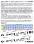
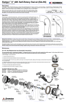
FIN FAN KIT (FF-100-XX)
USER MANUAL
PL 609 REV A
(09/2015)
TABLE OF CONTENTS
.MANUFACTURER’S INFORMATION.. . . . . . . . . . . . . . . . . . . . . . . . . . . . . . . . . . . . . . . . . . . . . . . . . . . . . . . . . . . . . . . . 3
SPECIFICATIONS. . . . . . . . . . . . . . . . . . . . . . . . . . . . . . . . . . . . . . . . . . . . . . . . . . . . . . . . . . . . . . . . . . . . . . . . . . . . . . . . . . . . . . . . . 3
DESCRIPTION OF EQUIPMENT AND INTENDED USE. . . . . . . . . . . . . . . . . . . . . . . . . . . . . . . . . . . . 3
KEY FEATURES. . . . . . . . . . . . . . . . . . . . . . . . . . . . . . . . . . . . . . . . . . . . . . . . . . . . . . . . . . . . . . . . . . . . . . . . . . . . . . . . . . . . . . . . . . . . 3
CE DECLARATION OF CONFORMITY. . . . . . . . . . . . . . . . . . . . . . . . . . . . . . . . . . . . . . . . . . . . . . . . . . . . . . . . . . . . 4
WARNING AND SAFETY INSTRUCTIONS. . . . . . . . . . . . . . . . . . . . . . . . . . . . . . . . . . . . . . . . . . . . . . . . . . . . . . . . 5
OPERATOR TRAINING. . . . . . . . . . . . . . . . . . . . . . . . . . . . . . . . . . . . . . . . . . . . . . . . . . . . . . . . . . . . . . . . . . . . . . . . . . . . . . . . . . 5
PERSONAL PROTECTIVE EQUIPMENT REQUIREMENTS.. . . . . . . . . . . . . . . . . . . . . . . . . . . . . . 5
PRE-RUN SAFETY CHECK. . . . . . . . . . . . . . . . . . . . . . . . . . . . . . . . . . . . . . . . . . . . . . . . . . . . . . . . . . . . . . . . . . . . . . . . . . . 6
SYSTEM ASSEMBLY - OVERVIEW .. . . . . . . . . . . . . . . . . . . . . . . . . . . . . . . . . . . . . . . . . . . . . . . . . . . . . . . . . . . . . . . . . . 7
FIN FAN KIT SET-UP. . . . . . . . . . . . . . . . . . . . . . . . . . . . . . . . . . . . . . . . . . . . . . . . . . . . . . . . . . . . . . . . . . . . . . . . . . . . . . . . . . . . . . . . . 8
HOSE STOP COLLET AND BACK OUT PREVENTION. . . . . . . . . . . . . . . . . . . . . . . . . . . . . . . . . . . . 13
PNEUMATIC SUPPLY LINE CONNECTIONS.. . . . . . . . . . . . . . . . . . . . . . . . . . . . . . . . . . . . . . . . . . . . . . . . . . 14
OPERATION. . . . . . . . . . . . . . . . . . . . . . . . . . . . . . . . . . . . . . . . . . . . . . . . . . . . . . . . . . . . . . . . . . . . . . . . . . . . . . . . . . . . . . . . . . . . . . . . . . . . . . 14
MAINTENANCE. . . . . . . . . . . . . . . . . . . . . . . . . . . . . . . . . . . . . . . . . . . . . . . . . . . . . . . . . . . . . . . . . . . . . . . . . . . . . . . . . . . . . . . . . . . . . . . . . 14
STORAGE, TRANSPORTATION, AND HANDLING. . . . . . . . . . . . . . . . . . . . . . . . . . . . . . . . . . . . . . . . . . . . 14
PARTS DIAGRAMS. . . . . . . . . . . . . . . . . . . . . . . . . . . . . . . . . . . . . . . . . . . . . . . . . . . . . . . . . . . . . . . . . . . . . . . . . . . . . . . . . . . . . . . . . . . . 15
TERMS AND CONDITIONS. . . . . . . . . . . . . . . . . . . . . . . . . . . . . . . . . . . . . . . . . . . . . . . . . . . . . . . . . . . . . . . . . . . . . . . . . . . . . . . 18
2
866-795-1586 • WWW.STONEAGETOOLS.COM
MANUFACTURER’S INFORMATION
StoneAge Inc.
Andrew Birt Consulting Ltd.
466 S. Skylane Drive
UK
Durango, CO 81303, USA
Phone: 970-259-2869
Toll Free: 866-795-1586
www.stoneagetools.com
This manual must be used in accordance with all applicable national laws. The manual shall be regarded as a part of the machine
and shall be kept for reference until the final dismantling of the machine, as defined by applicable national law(s).
SPECIFICATIONS
Fin Fan Kit Assembly Includes:
Fin Fan Snout Assembly Qty. 1
Fin Fan Clamp Assembly Qty. 2
Fin Fan Guide Assembly Qty. 1
DESCRIPTION OF EQUIPMENT AND
INTENDED USE
KEY FEATURES:
• The StoneAge Fin Fan Kit is a specifically engineered accessory
for the ABX-2L Hose Tractor “hands-free” heat exchanger tube
cleaning system. The Fin Fan Kit adapts the ABX-2L for easy
mounting to a Fin Fan header box for efficient tube cleaning.
• The Fin Fan Snout and Guide Assemblies provide anti-withdrawal
protection, and precise tube pitch adjustment.
• • • • Modular, lightweight, fully adjustable, design
Quick install
Utilizes 2.5 in. (6.35 cm) box rail cut to custom lengths to
accommodate any size Fin Fan Face dimension
Stainless Steel air motors
2 sizes of clamp attachment options are available for taller
Fin Fan Faces
Works with the ABX-2L Hose Tractor, CB-ABX Control Box, and
LWP-500 Light Weight Positioner
866-795-1586 • WWW.STONEAGETOOLS.COM
3
CE DECLARATION OF CONFORMITY
In accordance with BS EN ISO/IEC 17050-1:2010
We:
StoneAge, Inc. 466 South Skylane Drive Durango, CO 81303, USA
Declare that:
Equipment: Fin Fan Kit Assembly
Model name: FF-100-XX Is in accordance with the following Directives:
2006/42/EC Conforms to the Essential Health and Safety Requirements of the Machinery Directive
Has been designed and manufactured to the relevant parts of the following specifications:
EN ISO 12100:2010
Safety of machinery - General principles for design - Risk assessment and risk reduction
I hereby declare that the equipment named above has been tested and found to comply with the relevant sections of the
above referenced specifications and directives.
Signed ______________________________________________________
Date _
09/18/2015__________
Andrew Birt
Independent Dealer Manager
StoneAge, Inc., Worcester, UK
The technical file for the Fin Fan Kit Assembly (FF-100-XX) User Manual is maintained at: StoneAge, Inc. 466 South
Skylane Drive, Durango, CO 81303, USA
4
866-795-1586 • WWW.STONEAGETOOLS.COM
WARNING AND SAFETY INSTRUCTIONS
OPERATOR TRAINING
Managers, Supervisors, and Operators MUST be trained in Health
and Safety Awareness of High-pressure Water Jetting and hold
a copy the Water Jetting Association (WJA) Code of Practice, or
equivalent (see www.waterjetting.org.uk).
Operators MUST be trained to identify and understand all applicable
standards for the equipment supplied. Operators should be trained
in manual handling techniques to prevent bodily injury.
StoneAge has designed and manufactured this equipment
considering all hazards associated with its operation. StoneAge
assessed these risks and incorporated safety features in the design.
StoneAge WILL NOT accept responsibility for the results of misuse.
Operators MUST read, understand, and follow the Operational and
Training Requirements (Section 7.0) of WJTA-IMCA’s Recommended
Practices For The Use Of High-pressure Waterjetting Equipment, or
equivalent.
Operators MUST read, understand and follow the Warnings,
Safety Information, Assembly, Installation, Connection, Operation,
Transport, Handling, Storage, and Maintenance Instructions detailed
in this manual.
The risk assessment MUST consider potential material or substance
hazards including:
• • IT IS THE RESPONSIBILTY OF THE INSTALLER/OPERATOR to
conduct a job specific risk assessment prior to use. Job specific risk
assessment MUST be repeated for each different set up, material,
and location.
• The risk assessment MUST conform to the Health and Safety at
Work Act 1974 and other relevant Health and Safety legislation.
• • • • • • • • • PERSONAL PROTECTIVE EQUIPMENT REQUIREMENTS
Use of Personal Protective Equipment (PPE) is dependent on
the working pressure of water and the cleaning application.
Managers, Supervisors, and Operators MUST carry out a job
specific risk assessment to define the exact requirements for PPE.
See Protective Equipment for Personnel (Section 6) of WJTAIMCA’s Recommended Practices For The Use Of High-pressure
Waterjetting Equipment for additional information.
Hygiene - Operators are advised to wash thoroughly after all
waterjetting operations to remove any waterblast residue which may
contain traces of harmful substances.
First aid provision - users MUST be provided with suitable first aid
facilities at the operation site.
Aerosols
Biological and microbiological (viral or bacterial) agents
Combustible materials
Dusts
Explosion
Fibers
Flammable substances
Fluids
Fumes
Gases
Mists
Oxidizing Agents
PPE may include:
• Eye protection: Full face visor
• Foot protection: Kevlar® brand or steel toe capped,
waterproof, non-slip safety boots
• Hand protection: Waterproof gloves
• Ear protection: Ear protection for a minimum of 85 dBA
• Head protection: Hard hat that accepts a full face visor and
ear protection
• Body protection: Multi-layer waterproof clothing approved for
waterjetting
• Hose protection: Hose shroud
• Respiratory protection: May be required; refer to job specific
risk assessment
866-795-1586 • WWW.STONEAGETOOLS.COM
5
WARNING AND SAFETY INSTRUCTIONS
WARNING
Operations with this equipment can be potentially hazardous.
Caution MUST be exercised prior to and during machine and water
jet tool use. Please read and follow all of these instructions, in addition
to the guidelines in the WJTA Recommended Practices handbook,
available online at www.wjta.org. Deviating from safety instructions
and recommended practices can lead to severe injury and/or death.
Refer to WJTA-IMCA’s, Recommended Practices For The Use Of
High-pressure Waterjetting Equipment and/or The Water Jetting
Association’s, WJA Code of Practice for additional safety information.
• Complete a job specific risk assessment and act on the resulting
actions.
• Adhere to all site specific safety procedures.
• Do not exceed the maximum operating pressure specified for
any component in a system.
• The immediate work area MUST be marked off to keep out
untrained persons.
• Ensure the waterblasting zone is properly barricaded and that
warning signs are posted.
• Inspect the equipment for visible signs of deterioration,
damage, and improper assembly. Do not operate if damaged,
until repaired.
• Ensure the work place is free of unnecessary objects (e.g. loose
parts, hoses, tools).
• Ensure all Operators are using the correct Personal Protective
Equipment (PPE).
• Check that the air hoses are properly connected and tight.
• Check all hoses and accessories for damage prior to use. Do
not use damaged items. Only high quality hoses intended for
waterblast applications should be used as high-pressure hoses.
• Check all high-pressure threaded connections for tightness.
• Make sure all threaded connections are tight and free of leaks.
• Users of the Fin Fan Kit Assembly (FF-100-XX) MUST be
trained and/or experienced in the use and application of highpressure technology and cleaning, as well as all associated
safety measures, according to the WJTA Recommended
Practices for the use of High-pressure Waterjetting Equipment.
• • • 6
PRE-RUN SAFETY CHECK
An anti-withdrawal device (back-out preventer) MUST be used
at all times. The back-out prevention device is the Hose Stop
Collet located within the Fin Fan Snout Assembly. StoneAge
offers several different size Hose Stop Collets. The Collet Size
Reference guide is located on the Vertical Drive Assembly and
in the Part Diagram section of this manual.
The Control Box should be located in a safe location where
the Operator has good visibility of the pipe and hose. The
Fin Fan Kit Assembly (FF-100-XX) and Control Box MUST be
supervised at all times and should never be left unattended.
Always de-energize the system before servicing or replacing any
parts. Failure to do so can result in severe injury and/or death.
• **Ensure
that a anti-withdrawal device (back-out
preventer), and all other applicable safety devices are
installed and set-up properly.**
• Test the Control Box before operating the Fin Fan Kit Assembly
(FF-100-XX) with high-pressure water to verify the control valves
move the hose in the intended direction, and that the dump valve
and hose clamp are working properly.
• Ensure that Operators never connect, disconnect, or tighten
hoses, adapters, or accessories with the high-pressure water
pump unit running.
• Ensure no personnel are in the hydroblasting zone.
866-795-1586 • WWW.STONEAGETOOLS.COM
SYSTEM ASSEMBLY - OVERVIEW
FIN FAN KIT ASSEMBLY
**RAIL STOP
(FF-100-XX)
**RAIL
STOP
DETAIL A
#
PART NUMBER
-20 QTY
1
FF 101-XX FIN FAN SPRING SNOUT ASSY
1
2
FF 102-XX FIN FAN CLAMP ASSY
1
3
FF 103 FIN FAN GUIDE ASSY
2
LINE ITEMS
#
PART NUMBER
-20 QTY
4
BU 002.1-XX HORIZONTAL DRIVE RAIL (FIN FAN BUNDLE WIDTH PLUS 30
INCHES)
1
5
BU 002-XX VERTICAL DRIVE RAIL (FIN FAN BUNDLE HEIGHT PLUS 18 INCHES)
1
6
FF 121-XXX HOSE STOP COLLET SINGLE, .XXX
2
7
ABX 116-XX GUIDE TUBE, .546 ID / 14 mm
**HORIZONTAL DRIVE
ASSEMBLY
2
ABX 117-XX GUIDE TUBE, .674 ID / 17 mm
ABX 119-XX GUIDE TUBE, .745 ID / 19 mm
OPTIONAL ITEMS
#
PART NUMBER
-20/Default/QTY
8**
LWP 501 HORIZONTAL DRIVE ASSY
1
9**
LWP 502 VERTICAL DRIVE ASSY
1
10**
BU 152 RAIL STOP ASSY
2
11
SA 567-MP9LMP9L-XX NIPPLE
SA 567-MP9RMP9R-XX NIPPLE
12
AF 073-MP9LMP9L-XSL COUPLING
AF 073-MP9RMP9R-XSL COUPLING
2
2
**OPTIONAL ITEMS
ARE STANDARD
PARTS FROM THE
LIGHT WEIGHT
POSITIONER (LWP500).
**VERTICAL DRIVE
ASSEMBLY
DETAIL A
866-795-1586 • WWW.STONEAGETOOLS.COM
7
FIN FAN KIT SET-UP
FIN FAN KIT STEP BY STEP SET-UP
1. Mount the Fin Fan Clamp Assemblies to the tube bundle as shown. The Clamps should be as square to the bundle as possible.
Ratchet the yellow Handle Assembly until tight. (Figure 1)
2. If more stand-off is needed from the face of the bundle, it is possible to adjust the Clamp by depressing the tang on the bottom of the
vertical bar, sliding off the yellow Handle Assembly, unscrewing the Clamp from the Channel, and moving the Clamp to the open slot.
Relocate the screw to the next position, tighten, and attach the yellow handle assembly. (Figure 2)
CLAMP
ADJUSTMENT
SLOT
CLAMP
SCREW
TANG
FIGURE 1
NOTE: Fin Fan face, shown for graphic
representation only. Not included in assembly.
FIGURE 2
3. Loosen the Horizontal Mounting Plate Clamps and the Slide the Horizontal Rail (slots facing out) in between the Clamp Finger and
Rail Clamp. The Horizontal Rail should be ordered 30” (762 mm) longer than width of the tube bundle to provide complete coverage
with a single installation. (Figure 3)
4. Position the Horizontal Rail so that it extends 30” (762 mm) beyond the tube bundle as shown in (Figure 4). This is to allow the
Carriage to travel far enough to reach the tubes located farthest to the left. Tighten the Clamps securing the rail to the Mounting
Plates. Horizontal Rail longer than 150” (3810 mm) will require additional Horizontal Mounting Plate Clamps. spaced 75” (1905 mm)
apart. Clamps Spacing: Max spacing between clamps = 72” (1828 mm) Max spacing from end of rail = 50” (1270 mm)
HORIZONTAL
MOUNTING
PLATE
CLAMPS
FIGURE 3
30” /
762 mm
FIGURE 4
8
866-795-1586 • WWW.STONEAGETOOLS.COM
FIN FAN KIT SET-UP
5. Loosen the Quick Adjust Handle and pull the gearbox away from the carriage plate. This will allow the Horizontal Drive Carriage to
roll onto the rail without pneumatic power. (Figure 5)
6. Locate the Carriage on the rail and push the gearbox toward the rail to engage the drive gear into the rail slots. Verify the drive gear is
engaging the slots correctly and retighten the adjustable handle. (Figure 6)
QUICK
ADJUST
HANDLE
CARRIAGE
PLATE
DRIVE GEAR
ENGAGEMENT
FIGURE 6
FIGURE 5
BACKSIDE VIEW OF GEAR ENGAGEMENT
(RAIL IS TRANSPARENT FOR CLARITY)
7. Loosen the Horizontal Mounting Plate Clamp. Install the Vertical Rail with (slots facing out) between the Clamp Finger and Rail
Clamp. (Figure 7)
8. Position the Vertical Rail so that it is centered with the face of the tube bundle. The Vertical Rail should be ordered 18” (457 mm)
taller than the height of the tube bundle so that it extends vertically beyond the tube bundle face. Secure the Horizontal Mounting Plate
Clamp when the Vertical Rail is in position. (Figure 8)
FIGURE 7
HORIZONTAL
MOUNTING
PLATE
CLAMP
18” /
457 mm
FIGURE 8
866-795-1586 • WWW.STONEAGETOOLS.COM
9
FIN FAN KIT SET-UP
9. Loosen the Quick Adjust Handle and pull the gearbox away from the carriage plate. This will allow the Vertical Drive Carriage to roll
onto the rail without pneumatic power. (Figure 9)
FIGURE 9
10. Locate the Carriage on the rail and push the gearbox toward the rail to engage the drive gear into the rail slots. Verify the drive gear is
engaging the slots correctly and retighten the adjustable handle. (Figure 10)
NOTICE
Verify the Mounting Plates are securely tightened. Verify both Drive Carriages are engaged with the rails and the Quick Adjust Handles
are tightened.
WARNING
Never loosen the Vertical Drive once the Fin Fan Snout Assembly is installed, as it may result in the Carriage falling vertically down. This
may cause damage and/or injury.
DRIVE GEAR
ENGAGEMENT
FIGURE 10
10
866-795-1586 • WWW.STONEAGETOOLS.COM
VERTICAL DRIVE INSTALLED
ON VERTICAL RAIL (SHOWN
FOR REFERENCE)
FIN FAN KIT SET-UP
11. Using a 9/16 in. wrench, loosen all four Guide Clamp Bolts located on the Vertical Carriage. Install the Guide Plate Assembly into the
Guide Clamps. (Figure 11)
12. Align the edge of the Guide Plate Assembly to the Edge of the Carriage Plate. This will offset both bolt patterns and allow for easier
access when tightening the Guide Clamp Bolts. (Figure 12)
OFFSET BOLT
PATTERNS FOR
EASE OF ACCESS
FIGURE 11
ALIGN GUIDE
EDGE WITH
EDGE OF
CARRIAGE
PLATE
GUIDE
CLAMP
BOLTS
FIGURE 12
13. Remove the Quick Release Pins from the ABX-2L Hose Tractor Mounting Bracket. Slide the Fin Fan Spring Snout Block into the
Mounting Bracket on the ABX-2L Hose Tractor. Install the Quick Release Pins through the Mounting Bracket on the Hose Tractor and
the Block on the Fin Fan Spring Snout Assembly. (Figure 13)
FIN FAN SPRING
SNOUT BLOCK
FIGURE 13
866-795-1586 • WWW.STONEAGETOOLS.COM
11
FIN FAN KIT SET-UP
14. Install the Banshee tools (NOT INCLUDED IN FIN FAN KIT) on the end of the High Pressure Hose Fittings before running the hoses
through the ABX-2L Hose Tractor and the Fin Fan Snout Assembly. This will protect the threads on the Hose Ends. Assuming the
ABX-2L Hose Tractor and Control Box are connected to an air supply, remove the Quick Release Pins and Hose Stop Collets as shown
in (Figure 14), and run the hoses through the Fin Fan Snout Assembly until the Banshee tools exit the Hose Guide Tubes.
15. Replace the Hose Stop Collets and Quick Release Pins. (Figure 15)
FIGURE 14
WARNING
Appropriate size Collet selection is CRITICAL to ensuring proper
backout prevention of the tool.
See “RECOMMENDED COLLETS
FOR COMMON HOSE SIZES” plate,
attached to Fin Fan Snout Assembly.
FIGURE 15
NOTICE
Extension nipples and slimline couplers are recommended on the end of the hoses to easily bridge the gap in the header. The Banshee
tools, recommended extension nipples, and slimline couplers are NOT included in the Fin Fan Kit Asssembly. (Figure 14.5)
If using BN18s, StoneAge offers a reduce O.D. SlimlIne Coupler for use with standard Guide Tubes.
*OPTIONALBANSHEE TOOLS
*OPTIONALEXTENSION NIPPLES
*OPTIONALSLIMLINE COUPLERS
FIGURE 14.5
12
866-795-1586 • WWW.STONEAGETOOLS.COM
*OPTIONAL-HIGH
PRESSURE HOSES
FIN FAN KIT SET-UP
16. The Snout Block and Guide Tubes are transparent in (Figure 16) to illustrate how the Hose Stop Collets act as back out prevention
devices.
WARNING
Test the back out prevention by retracting the Banshee tools into the Guide Tubes. The Hose Stop Collets should prevent the
Hose Crimp from moving back into the Fin Fan Snout Assembly. The proper selection and installation of the Hose Stop Collets is
critical to preventing the back out of the tools.
SNOUT BLOCK
(TRANSPARENT)
HOSE STOP COLLETS
*OPTIONALEXTENSION NIPPLE
FIN FAN
SNOUT ASSEMBLY
*OPTIONAL-HIGH
PRESSURE HOSES
GUIDE TUBES
(TRANSPARENT)
*OPTIONALSLIMLINE COUPLERS
*OPTIONALBANSHEE TOOLS
FIGURE 16
17. Install Guide Tubes simultaneously, but secure the left Guide Tube into the Fixed Clamp on the Guide Plate first. The Guide Tubes
should be set 1/4”-1/2” (6 - 13 mm) away from the face of the tube bundle (Figure 17).
18. Install the right Guide Tube into the Adjustable Clamp next and adjust the pitch. The pitch can be set between 1-3/4” (44 mm) and 4”
(102 mm) by sliding the Adjustable Clamp in or out and tightening in the desired position (Figure 18).
1/4”-1/2”
(6-13 mm)
PITCH
GUIDE TUBES
FIGURE 17
FIXED CLAMP
GUIDE TUBES
ADJUSTABLE
CLAMP
FIGURE 18
866-795-1586 • WWW.STONEAGETOOLS.COM
13
FIN FAN KIT SET-UP
PNEUMATIC SUPPLY LINE CONNECTIONS
19. Verify the ABX-2L Hose Tractor is connected to the Control Box with two 1/2 in. (13 mm) JIC hoses and one 1/4 in. (6 mm) JIC hose.
Remove the dust caps from the Joint Industry Council (JIC) fittings of the Control Box and the Vertical and Horizontal Positioners.
Connect the Vertical and Horizontal Positioners to the Control Box with two each, 1/4 in. (6 mm) JIC hoses. Verify the Control Box moves
the both the Vertical and Horizontal Carriages in the appropriate directions.
HORIZONTAL
POSITIONER
1/4” CONNECTIONS
VERTICAL
POSITIONER
1/4” CONNECTIONS
OPERATION
Reference your ABX-2L User Manual for additional operating instructions
STORAGE, TRANSPORTATION, AND HANDLING
Use mild soapy water to clean the kit components in order to remove corrosive materials. Before storing the kit, use compressed air to blow
off debris and moisture. Apply a small amount of air tool oil directly into the Horizontal and Vertical Drive fittings. Then, briefly operate the
controls at slow speed for a short duration in each direction to coat the interior parts of the motor. Install the dust caps onto all fittings to
keep moisture and dirt out.
The FIN FAN KIT ASSEMBLY (FF-100-XX), can be broken down into smaller components that should be stored in a clean and dry area.
14
866-795-1586 • WWW.STONEAGETOOLS.COM
PARTS DIAGRAM
FIN FAN KIT ASSEMBLY (FF-100-XX)
#
PART NUMBER
-20/Default/QTY
1
FF 101-XX FIN FAN SPRING SNOUT ASSY
1
2
FF 102-XX FIN FAN CLAMP ASSY
2
3
FF 102-XX FIN FAN CLAMP ASSY
-
FF 103 FIN FAN GUIDE ASSY
1
LINE ITEMS
#
PART NUMBER
-20/Default/QTY
4
BU 002.1-XX HORIZONTAL DRIVE RAIL (FIN FAN BUNDLE WIDTH PLUS 30 INCHES)
1
5
BU 002-XX VERTICAL DRIVE RAIL (FIN FAN BUNDLE HEIGHT PLUS 18 INCHES)
1
6
FF 121-XXX HOSE STOP COLLET SINGLE, .XXX
2
7
ABX 116-XX GUIDE TUBE, .546 ID / 14 mm
ABX 117-XX GUIDE TUBE, .674 ID / 17 mm
2
ABX 119-XX GUIDE TUBE, .745 ID / 19 mm
OPTIONAL ITEMS
#
PART NUMBER
-20/Default/QTY
8
LWP 501 HORIZONTAL DRIVE ASSY
1
9
LWP 502 VERTICAL DRIVE ASSY
1
10
BU 152 RAIL STOP ASSY
2
11
SA 567-MP9LMP9L-XX NIPPLE
SA 567-MP9RMP9R-XX NIPPLE
12
AF 073-MP9LMP9L-XSL COUPLING
AF 073-MP9RMP9R-XSL COUPLING
2
2
866-795-1586 • WWW.STONEAGETOOLS.COM
15
PARTS DIAGRAM
FIN FAN KIT ASSEMBLY (FF 101-XX)
FIN FAN SPRING SNOUT ASSY
-84 QTY
7
FF 132 FABRIC HEAT SHRINK TUBING, LG
1
CUT TO 66”
1
FF 111 CAP, SNOUT BLOCK GUIDE TUBE
2
8
FF 133 FABRIC HEAT SHRINK, SM
1
CUT IN HALF (2 X 18”)
2
FF 112 CAP, SNOUT BLOCK SPRING
2
9
FF 135 HEAVY DUTY SHRINK WRAP, 1.50 BEFORE
1
CUT IN HALF (2 X 4.5”)
3
FF 113 CAP, SNOUT BRACKET
1
10
FF 136 HEAVY DUTY SHRINK WRAP, 2.00 BEFORE
1
CUT IN HALF (2 X 4.5”)
4
FF 115 SNOUT BLOCK, FIN FAN
2
11
FF 159-XX FLAT WIRE SPRING, SNOUT
2
5
FF 116 MOUNTING BRACKET INSIDE, SNOUT
1
12
GS 325-04 SHCS .25-20 X 1.00 SS (BC 053)
12
6
FF 131 QUICK RELEASE PIN .25X 1.25
2
#
PART NUMBER
FIN FAN KIT ASSEMBLY (FF 102-XX)
FIN FAN CLAMP ASSEMBLY
#
16
PART NUMBER
-20/Default/QTY.
6
GW 331-L LOCK WASHER SS
4
1
FF 122 CLAMP WELDMENT
1
7
SRT 549 HORIZONTAL RAIL CLAMP
1
2
FF 123-20 CLAMP, FIN FAN HEADER
1
8
SRT 551 CLAMP FINGER
1
3
GB 331-20 BOLT, HEX .31-18 X 5.00 SS
4
9
SRT 552 ADJUSTABLE RAIL CLAMP
1
4
GSF 337-03 FHCS .37-16 X .75 LG SS
1
10
SRT 556 ADJUSTABLE HANDLE .38-16 X 1.56 SS
1
5
GSSH 0375-0500-SS SHOULDER SCREW
2
866-795-1586 • WWW.STONEAGETOOLS.COM
PARTS DIAGRAM
FIN FAN KIT ASSEMBLY (FF 103)
FIN FAN GUIDE ASSEMBLY
#
PART NUMBER
QTY.
1
FF 138 ABX 2L GUIDE WELDMENT
1
2
FF 139 GUIDE TUBE CLAMP
2
3
FF 140 PLATE, THREADED
1
4
GB 337-07 BOLT, HEX .37-16 X 1.75 SS
4
5
GW 337-L LOCK WASHER SS
4
GUIDE TUBE AND COLLET REFERENCE CHARTS
StoneAge PART NUMBER GUIDE TUBE REFERENCE CHART
SA PART NUMBER
SA TOOL
I.D. DIAMETER
LENGTH
ABX 115-XX
BN9.5
0.459 in. / 12 mm
XX in. / XX mm
ABX 116-XX
BN13
0.546 in. / 14 mm
XX in. / XX mm
ABX 117-XX
BN15
0.674 in. / 17 mm
XX in. / XX mm
ABX 119-XX
BN18
0.745 in. / 19 mm
XX in. / XX mm
StoneAge PART NUMBER
COLLET REFERENCE CHART
SA PART NUMBER
RECOMMENDED COLLETS FOR COMMON
HOSE SIZES
COLLET SIZE
SPIR STAR
PARKER
0.297 in. / 8 mm
3/2
2240D-02
FF 121-328
0.328 in. / 8 mm
3/4, 4/2
2240D-025, 2240D-02
FF 121-406
0.406 in. / 10 mm
5/2, 3/6
2240D-03
FF 121-438
0.438 in. / 11 mm
4/4
2448D-25
FF 121-460
0.460 in. / 12 mm
4/6, 5/4, 6/2
2240D-04
FF 121-484
0.484 in. / 12 mm
FF 121-516
0.516 in. / 13 mm
6/4
2440D-04
FF 121-547
0.547in. / 14 mm
5/6, 8/2
2240D-05, 2740D-03
FF 121-594
0.594 in. / 15 mm
8/4
FF 121-625
0.625 in. / 16 mm
FF 121-297
2640D-25
866-795-1586 • WWW.STONEAGETOOLS.COM
2240D-05
17
TERMS AND CONDITIONS
1. Acceptance of Terms and Conditions. These Terms and Conditions
shall operate as Seller’s acceptance of Buyer’s purchase order, and such
acceptance is made expressly conditional on assent by Buyer to the
Terms and Conditions. Such assent shall be deemed to have been given
unless written notice of objection to any of such Terms and Conditions
(including inconsistencies between Buyer’s purchase order and this
acceptance) is given by Buyer to Seller promptly on receipt hereof.
Seller desires to provide its Buyer with prompt and efficient service.
However, to negotiate individually the terms of each sales contract
would substantially impair Seller’s ability to provide such service.
Accordingly, products furnished and services rendered by Seller are
sold only on the Terms and Conditions stated herein. Notwithstanding
any Terms or Conditions on Buyer’s order, Seller’s performance of any
contract is expressly made conditional on Buyer’s agreement to Seller’s
Terms and Conditions of sale unless otherwise specifically agreed to in
writing by Seller. In the absence of such agreement, commencement of
performance, shipment and/or delivery shall be for Buyer’s convenience
only and shall not be deemed or construed to be an acceptance of
Buyer’s Terms and Conditions. PRODUCTS SOLD BY SELLER ARE
DESIGNED AND INTENDED TO BE USED AT HIGH PRESSURES AND
SPEEDS, AND MAY BE DANGEROUS IF OPERATED IMPROPERLY OR
WITHOUT THE USE OF APPROPRIATE SAFETY DEVICES AND GUARDS.
BUYER IS CAUTIONED TO CAREFULLY READ AND UNDERSTAND
THESE TERMS AND CONDITIONS, AS THEY HAVE IMPORTANT LEGAL
CONSEQUENCES.
2. Payment/Prices. Unless other arrangements have been made in
writing between Seller and Buyer, payment for product delivered shall be
made upon receipt of invoice. The prices shown on the face hereof are
those currently in effect. Prices invoiced shall be per price list in effect at
the time of shipment. Prices are subject to increase for inclusion of any
and all taxes which are applicable and which arise from the sale, delivery
or use of Seller’s products or services and for the collection of which
Seller is or may be responsible to any governmental authority unless
acceptable exemption certificates are provided by Buyer in accordance
with law. Buyer shall pay all charges for transportation and delivery and
all excise, order, occupation, use or similar taxes, duties, levies, charges
or surcharges applicable to the equipment or services being purchased,
whether now in effect or hereafter imposed by any governmental
authority, foreign or domestic.
3. Warranty. Subject to the limitations and conditions hereinafter set
forth, Seller warrants to the original Buyer that its products are free from
defects in workmanship and material for a period of one (1) year from
shipment date. Seller’s obligation under this warranty shall be limited
to repairing, replacing or issuing a credit for, at Seller’s option, any
products or services it finds to be defective in material or workmanship.
In no event shall Seller be liable for any incidental, consequential or
indirect damages of any kind. THIS WARRANTY SHALL BE IN LIEU
OF ANY OTHER WARRANTY, EXPRESSED OR IMPLIED, INCLUDING
ANY WARRANTY FOR MERCHANTABILITY OR FITNESS FOR ANY
PARTICULAR PURPOSE. No statement or recommendation made by
Seller or its representative to Buyer or User shall constitute a warranty by
Seller or a waiver or modification to any of the provisions hereof or create
any liability for Seller. All warranty claims are subject to the exclusions
and limitations set forth below:
18
a. The warranty shall not apply if the product or service (1) has been
subject to misuse, negligence or accident; (2) has not been installed or
operated in accordance with Seller’s recommendations; (3) has been
operated under more severe conditions than those specified for the
particular product or service; (4) has been operated beyond the rated
capacity of the product; or (5) has been repaired or altered outside
Seller’s facilities or in any way so as, in Seller’s judgment, to affect its
stability or reliability.
b. Products that Seller furnishes, but does not manufacture, carry
only the warranty of the Manufacturer of such products. Where other
Manufacturers’ or Suppliers’ products used in Seller’s products or
services prove defective, Seller’s liability shall exist only to the extent
that Seller is able to recover from such Manufacturers or Suppliers for
such defects.
c. Any warranty granted by Seller to the Buyer shall be deemed void
if any goods covered by such warranty are used for any purpose not
recommended or permitted. In addition, the Buyer shall indemnify
Seller and hold Seller harmless from and against any and all claims,
damages, losses, costs, expenses and other liability of whatever nature
that Seller suffers or incurs by reason of any such unintended use.
d. Notice of defective product or service must be given in writing to
Seller by Buyer or User within fifteen (15) business days following
receipt of goods. Buyer or User shall keep such products or services
in an unaltered condition for examination by Seller’s representative. No
goods may be returned for credit or adjustment without prior written
permission from Seller.
4. Product Liability. Buyer specifically acknowledges that the products
being purchased may be operated at high speeds and/or pressures,
and that as such they may be inherently dangerous if not used correctly.
Buyer shall be solely responsible for the safe operation of the products
at all times and for determining the safety devices and guards that
may be required for the safe operation of the products. Buyer shall
undertake to specify and order all safety devices and guards necessary
for the safe operation of the equipment covered. All safety devices and
guards offered in Seller’s quotations are recommended for purchase.
Seller may provide necessary safety devices and guards not offered in
this quotation at an extra price in accordance with the specifications
of Buyer. Buyer shall at all times use and require its contractors to use
all necessary and appropriate safety devices, guards and proper safe
operating procedures. Buyer shall ensure that proper Operator training
is provided. Buyer shall not remove or modify any such devices, guards
or warning signs and shall insist on safe operating practices on the part
of its personnel. In no event shall Seller be responsible for any injuries to
persons or property caused by defects in any equipment, including by
way of illustration and not limitation, any pumps, compressors, fittings,
connections, components, piping or hoses up to the point that same are
connected to the product. Buyer agrees to indemnify and to save Seller
harmless from any and all liability or obligation incurred by or against
Seller, including costs and attorneys’ fees, to or by any persons injured
directly or indirectly in the operation of the equipment furnished under
the following conditions:
866-795-1586 • WWW.STONEAGETOOLS.COM
TERMS AND CONDITIONS
a. if Buyer fails to purchase and use necessary and appropriate safety
devices and guards as determined and/or recommended by Seller;
b. if Buyer fails to maintain in good working order such safety devices
and guards as are purchased from Seller;
c. if Buyer adds, omits, repairs, modifies, replaces or substitutes any
components on the equipment without permission from Seller;
d. if Buyer exceeds at any time the maximum safe loads, pressures or
speeds recommended by Seller for the equipment furnished hereunder
without the specific written consent of Seller; or
e. if Buyer otherwise fails to operate the product or equipment in
accordance with Seller’s printed instructions or otherwise negligently
operates the equipment.
5. Delivery. Seller is not obligated to make delivery by a specified
date, but will always use its best efforts to make delivery within the
time requested. All deliveries are based on F.O.B. Seller’s factory,
unless specifically agreed otherwise, and Buyer shall pay all shipping
costs and insurance from that point. Seller, in its sole discretion, will
determine and arrange the means and manner of transportation of
the products. Responsibility of Seller shall cease and Buyer assumes
all risk of loss or damages upon Seller’s delivery to and receipt by a
common carrier. Carriers shall be responsible for goods lost or damaged
in transit and Buyer shall immediately notify the carrier in writing of
such loss or damage. At Buyer’s request Seller will offer its assistance.
THE PROPOSED SHIPMENT DATE IS AN ESTIMATE. UNDER NO
CIRCUMSTANCES SHALL SELLER HAVE ANY LIABILITY WHATSOEVER
FOR LOSS OF USE OR FOR ANY DIRECT OR CONSEQUENTIAL
DAMAGES RESULTING FROM DELAY REGARDLESS OF THE
REASON(S). Shortages or errors must be reported within fifteen (15)
business days from receipt of shipment to secure adjustment. No
merchandise may be returned without securing written approval from
Seller. Seller will notify Buyer promptly of any material delay and will
specify the revised delivery date as soon as practicable. Seller shall
not be liable for any delay in delivery or performance, or for any failure
to manufacture, deliver or perform due to (a) any cause beyond its
reasonable control; (b) any act of God, act of Buyer, act of civil or military
authority, governmental priority, strike or other labor disturbance, flood,
epidemic, war, riot, delay in transportation or car shortage; or (c) inability
on account of any cause beyond the reasonable control of Seller to obtain
necessary materials, components, services or facilities. In the event of
any such delay, the date of delivery or of performance shall be extended
for a period equal to the time lost by reason of the delay.
limit or waive Seller’s right thereafter to enforce and compel strict
compliance with every Term and Condition thereof. If any provisions of
these Terms and Conditions are held to be invalid or unenforceable, such
invalidity or unenforceability shall not affect the validity or enforceability
of the other portions hereof.
8. Disputes. Buyer and Seller shall attempt in good faith promptly
to resolve any dispute arising under these Terms and Conditions by
negotiations between representatives who have authority to settle the
controversy. If unsuccessful, Buyer and Seller shall further attempt in
good faith to settle the dispute by nonbinding third-party mediation, with
fees and expenses of such mediation apportioned equally to each side.
Any dispute not so resolved by negotiation or mediation may then be
submitted to a court of competent jurisdiction in accordance with the
terms hereof. These procedures are the exclusive procedures for the
resolution of all such disputes between the parties. All sales, agreements
for sale, offers to sell, proposals, acknowledgments and contracts of
sale, including, but not limited to, purchase orders accepted by Seller,
shall be considered a contract under the laws of the State of Colorado
and the rights and duties of all persons, and the construction and effect
of all provisions hereof shall be governed by and construed according to
the laws of such state. A state or federal court located within the State
of Colorado shall have sole and exclusive jurisdiction over any litigation
concerning any such matters as well as any alleged defects of any
products or equipment covered thereby or damages sustained as a result
of such alleged defects. If any litigation is commenced between Seller
and Buyer, or their personal representatives, concerning any provision
hereof, the party prevailing in the litigation shall be entitled, in addition
to such other relief that is granted, to a reasonable sum as and for their
attorneys’ fees and costs in such litigation or arbitration.
STONEAGE TRADEMARK LIST
View the list of StoneAge’s trademarks and service marks and learn how
the trademarks should be used. Use of StoneAge trademarks may be
prohibited, unless expressly authorized.
http://www.StoneAgetools.com/trademark-list/
STONEAGE PATENT DATA
View the list of StoneAge’s current U.S. patent numbers and descriptions.
http://www.sapatents.com
6. Technical Advice. All technical advice, recommendations and
services of Seller are intended for use by persons having adequate skill,
at their own risk, and Seller assumes no responsibility, and Buyer hereby
waives all claims against Seller, for results obtained or damages incurred
from the use of Seller’s advice, recommendations and services.
7. Modification. These Terms and Conditions are intended by Seller
and Buyer to constitute a final, complete and exclusive expression of
agreement and cannot be supplemented or amended without Seller’s
prior written approval. Seller’s waiver of any breach, or failure to enforce
any of the Terms and Conditions at any time, shall not in any way affect,
866-795-1586 • WWW.STONEAGETOOLS.COM
19
1-866-795-1586 • www.STONEAGETOOLS.com
© 2015 StoneAge, Inc. All Rights Reserved