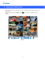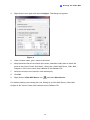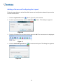
1
Quick Start Guide
GV-Control Center V3.2.0.0
Thank you for purchasing GV-Control Center. This guide is designed to assist the
new user in getting immediate results from the GV-Control Center. For advanced
information on how to use the GV-Control Center, please refer to GV-Control
Center User's Manual on Software DVD.
© 2014 GeoVision Inc. All rights reserved.
2014/12
English
CCSV32-QG-A
© 2014 GeoVision, Inc. All rights reserved.
Under the copyright laws, this manual may not be copied, in whole or in part, without the
written consent of GeoVision.
Every effort has been made to ensure that the information in this manual is accurate.
GeoVision, Inc. makes no expressed or implied warranty of any kind and assumes no
responsibility for errors or omissions. No liability is assumed for incidental or consequential
damages arising from the use of the information or products contained herein. Features and
specifications are subject to change without notice.
GeoVision, Inc.
9F, No. 246, Sec. 1, Neihu Rd.,
Neihu District, Taipei, Taiwan
Tel: +886-2-8797-8377
Fax: +886-2-8797-8335
http://www.geovision.com.tw
Trademarks used in this manual: GeoVision, the GeoVision logo and GV series products are
trademarks of GeoVision, Inc. Windows and Windows XP are registered trademarks of
Microsoft Corporation.
December 2014
Contents
1.
Introduction......................................................................................................................1
Packing List ..................................................................................................................................... 1
Options ............................................................................................................................................ 1
2.
Minimum System Requirements ....................................................................................2
Supported DVR Version .................................................................................................................. 3
3.
Installing Control Center.................................................................................................4
4.
Overview...........................................................................................................................5
The Control Center Main Window ................................................................................................... 5
The Toolbar...................................................................................................................................... 6
The Host List ................................................................................................................................... 8
The Group List................................................................................................................................. 9
5.
Creating Hosts and Groups ..........................................................................................10
Creating a Host...............................................................................................................................11
Creating a Group ........................................................................................................................... 12
6.
Connecting to Control Center ......................................................................................13
7.
Viewing Live Video ........................................................................................................14
8.
Running the Matrix View ...............................................................................................16
9.
Running the Video Wall.................................................................................................18
Setting Up a Video Wall Server ..................................................................................................... 18
Adding a Server and Configuring the Layout ................................................................................ 20
Activating the Channel and Layout................................................................................................ 21
10.
Playing Back Video......................................................................................................22
i
1. Introduction
Welcome to the GV-Control Center Quick Start Guide. In the following sections, you will learn
the basic requirements and configurations of using GV-Control Center. For the detailed
instructions of use, see the GV-Control Center User's Manual on the Software DVD.
Packing List
z
GV-USB Dongle
z
Software DVD
Options
Device
Description
GV-Keyboard V3
A GV-Keyboard V3 can be used to operate PTZ camera,
Matrix View, ViewLog and Video Wall. For details, see
GV-Keyboard V3 User’s Manual.
GV-Joystick
A GV-Joystick can be used in conjunction with GV-Keyboard
V3 to control PTZ channels from GV-Control Centers. For
details, see GV-Joystick User’s Manual.
Internal GV-USB Dongle
An Internal GV-USB Dongle provides the hardware watchdog
function to GV-Control Center server by restarting the
computer when Windows crashes.
1
2. Minimum System Requirements
Before installation, make sure your computer meets the following minimum requirements:
OS
64-bit
Windows 7 / 8 / 8.1 / Server 2008 R2 / Server 2012 R2
CPU
Core i7 2600K, 3.4 GHz
RAM
8 GB Dual Channels
Hard Disk
1 GB
Graphic Card
AGP or PCI-Express, 1024 x 768, 32-bit color
DirectX
9.0c
LAN Card
Gigabit Ethernet x 2
Hardware
Internal or External GV-USB Dongle
Note:
1. If you are using more than two graphic cards on a server, make sure they are of the
same brand, model and driver version to ensure maximum efficiency.
2. We do not recommend installing GV-Control Center and GV-Center V2 Pro on the
same PC. Running GV-Control Center and GV-Center V2 Pro on the same PC may
result in CPU overload error or system failure.
3. When you find CPU usage is high or live view is unsmooth (dropping frames), you may
need to increase the CPU thread and memory or decrease the number of connected
cameras to improve the system performance.
2
2
Minimum System Requirements
Software License
Free License
N/A
Maximum License
Unlimited
Increment for each
license
N/A
1. Control Center
2. Control Center + Video Wall (1 to 200 license)
Optional Combinations
3. Control Center + Vital Sign Monitor
4. Control Center + Vital Sign Monitor + Video Wall (1 to 200
license)
Dongle Type
Internal or external
Note:
1. For the Video Wall function, make sure you insert a GV-USB dongle with Video Wall
function to Control Center server.
2. It is recommended to use the internal GV-USB dongle to have the Hardware Watchdog
function which restarts the PC when Windows crashes or freezes.
Supported DVR Version
The Control Center is compatible with :
z
GV-System / GV-NVR V8.5 or later
z
GV-VMS V14.1 or later
3
3. Installing Control Center
1.
Plug in the GV-USB Dongle to the computer.
2.
Insert the Software DVD to your computer. It runs automatically and a window appears.
3.
To install the USB device driver, select Install or Remove GeoVision GV-Series Driver
and follow the on-screen instructions.
4.
To install GV-Control Center, select Install GeoVision GV-Control Center V3.1.2.0 and
click Yes to accept the License Agreement.
5.
Click GeoVision Control Center and follow the on-screen instructions.
Note:
1. By default, the GV-Control Center contains an Administrator account with the login
ID admin and no password.
2. You may also download the latest GV-Control Center from the GeoVision Website.
For details, see 2.1 Installation, GV-Control Center User’s Manual on the Software
DVD.
4
4. Overview
The Control Center Main Window
1
2
3
4
6
5
Figure 1
No. Name
Description
1
Toolbar
See Figure 2 later.
2
Host List
Displays hosts and its channels in a tree diagram. See Figure 3 later.
3
Group List
Displays hosts in Groups of VMD, I/O and E-Map. See Figure 4 later.
Displays images from the hosts. Drag and drop the cameras from the
4
Live View
Host List for live view display. See Displaying Multi Views, Chapter 3,
GV-Control Center User’s Manual on the Software DVD.
Click the tab to switch to the Layout List. The Layout List contains lists of
5
Layout List
layout template for video wall. See The Layout List, Chapter 8,
GV-Control Center User’s Manual on the Software DVD.
Displays the Instant Play window on the main window for playback. See
6
Instant Play
Instant Playback, Chapter 5, GV-Control Center User’s Manual on
Software DVD.
5
The Toolbar
1
2
3
4
5
6
14
15 16
17
18
19
8
7
20
9
10
11 12
13
21
Figure 2
No. Name
1
Configure
Description
Displays system settings including general settings, network settings,
VMD settings, Remote Desktop and Video Wall.
Configures position and resolutions of application windows, including
2
Application
GV-System / GV-VMS, Remote ViewLog, Remote E-Map, I/O Central
Position
Panel, and up to 8 matrices. See Application Position, Chapter 8,
GV-Control Center User’s Manual on Software DVD.
Opens the Search Host window, with which you can detect and add
3
Search Host
devices of the same LAN to the Host List and select a network card if you
have installed more than one.
4
5
6
Connect to
server
Search Server
Adds a server to Layout List of a Video Wall.
Searches for Video Wall servers. See Video Wall, Chapter 8, GV-Control
Center User’s Manual on Software DVD.
Open
Opens the activated layout on the Control Center’s main window. See
Activated
Video Wall, Chapter 8, GV-Control Center User’s Manual on Software
Layout
DVD.
Manages mass number of GV-IP Devices with integrated interface. You
can change/assign IP address, rename devices, assign NAS and view
7
Batch
storage space information of multiple GV-IP Devices. See Batch
Functions, Chapter 9, GV-Control Center User’s Manual on Software
DVD.
Searches for any remote servers with Remote Desktop service activated.
8
Search Server See Displaying Remote Monitor, Web Page and Playing Back Videos,
Chapter 8, GV-Control Center User’s Manual on Software DVD.
Displays the video wall Layout List on the main window. See The Layout
9
Layout List
10
Host List
Displays Host List on the main window.
11
Group List
Displays the Group List on the main window.
List, Chapter 8, GV-Control Center User’s Manual on Software DVD.
6
4
No. Name
Overview
Description
Displays live views collectively on the main window. Drag and drop
12
Live View
cameras for live view display. For more detail, see Displaying
Window
Multi-Views, Chapter 3, GV-Control Center User’s Manual on Software
DVD.
Displays the Instant Play window on the main window. See Instant
13
Instant Play
Playback, Chapter 5, GV-Control Center User’s Manual on Software
DVD.
Allows the Control Center to access a remote client GV-System /
14
Remote DVR GV-VMS. See Remote DVR, Chapter 6, GV-Control Center User’s
Manual on Software DVD.
15
16
17
Remote
Desktop
Remote
ViewLog
Remote
E-Map
Allows the Control Center to access a remote client GV-System /
GV-VMS and its desktop. See Remote Desktop, Chapter 6, GV-Control
Center User’s Manual on Software DVD.
Allows the Control Center to access the event files of different hosts and
play them back. See Remote ViewLog, Chapter 5, GV-Control Center
User’s Manual on Software DVD.
Allows you to monitor client DVR and GV-IP Devices on E-Maps. See
Remote E-Map, Chapter 9, GV-Control Center User’s Manual on
Software DVD.
Displays pop-up live views when a motion, input or temperature alert is
18
VMD System detected. See VMD Monitoring, Chapter 3, GV-Control Center User’s
Manual on Software DVD.
17
18
19
I/O Central
Collectively manages I/O devices of different hosts. See I/O Central
Panel
Panel, Chapter 7, GV-Control Center User’s Manual on Software DVD.
Broadcast
Service
Matrix Quick
Zoom
Speaks to multiple hosts over LAN or the Internet simultaneously. See
Audio Broadcast, Chapter 4, GV-Control Center User’s Manual on
Software DVD.
Displays a selected camera view on the primary monitor when multiple
monitors are used. For Matrix View, see Matrix View, Chapter 8,
GV-Control Center User’s Manual on Software DVD.
7
The Host List
1
2
3 4
5
6
7
8
Figure 3
No. Name
Description
1
Save
Saves the changes made in Host List.
2
Delete
Deletes the selected host.
3
Add Host
Adds a Host.
4
Host Settings
Displays the host settings of the selected host.
Camera
Click to watch live view, access Remote ViewLog and play back
Information
recordings instantly.
5
6
7
8
Remote
Control
Access applications including Remote DVR, Remote Desktop and Event
Data Query. See Remote DVR Applications, Chapter 6, GV-Control
Center User’s Manual on Software DVD.
Remote
Plays back recordings of the selected camera. See Remote ViewLog,
ViewLog
Chapter 5, GV-Control Center User’s Manual on Software DVD.
Microphone
Allows the user to speak to and listen to a selected host.
8
4
Overview
The Group List
1
2
3
4
5
6 7
8 9
Figure 4
No. Name
Description
1
Save
Saves the changes made in Group List.
2
Delete
Deletes the selected group.
3
4
5
Rename
Group
Add Group
Camera
Information
Renames the selected group.
Adds a new group under the selected category.
Looks up device information and access its live view.
6
Move up
Moves the selected camera up in its group.
7
Move down
Moves the selected camera down in its group.
8
Matrix
9
Displays matrix view. See Matrix View, Chapter 8, GV-Control Center User’s
Manual on Software DVD.
Remote
Plays back recordings of the selected camera. See Remote ViewLog,
ViewLog
Chapter 5, GV-Control Center User’s Manual on Software DVD.
9
5. Creating Hosts and Groups
To create hosts, you can use the Search Host function
(No. 3, Figure 2) to detect GV
devices and compatible third-party IP devices on the same LAN and add them to the Host List,
or you can follow the steps in the following section.
Note:
1. To use the Search Host function to locate GV devices, it is required to open TCP port
5201 on the client DVR, TCP port 5202 on the Video Server and Compact DVR, and
UDP port 5200 on the Control Center.
2. If antivirus software is installed, the Search Host function may be interfered and will
not detect the available hosts. In this case, turn off the antivirus software and try again.
10
5
Creating Hosts and Groups
Creating a Host
You can create a host of the DVR, Compact DVR, Video Server, IP Camera, I/O Box and
Recording Server. The Host Settings dialog box may look different among these devices. The
following steps are an example of adding an IP camera host.
1. On the Host List window, click the Add Host button
(No. 3, Figure 3) and select Add IP
Camera. This dialog box appears.
Figure 5
2. Type the host name, IP address, login ID and password of the host. Keep the
communication port as default, unless otherwise necessary.
3. Click the Update Information button to request the number of cameras, I/O modules and
streams of the host. When the update is complete, the message Update system
information successfully appears.
4. Optionally select Stream 1 or Stream 2 for live view display. By default, the Stream setting
is Auto and the received streaming is based on the streaming setting of the connected IP
camera.
5. Click OK to add the host.
11
Note:
1. To add a DVR host, it is required to enable Control Center Service at the DVR;
otherwise the message Unable to Connect will appear when accessing the live view.
See 6. Connecting to Control Center later.
2. The Control Center supports IP video devices using RTSP, ONVIF and PSIA
standards. To connect the IP device compatible with any of these standards, select
Protocol from the Brand drop-down list.
Creating a Group
You can group cameras from different hosts by location and purpose (such as matrix view
display).
1.
ON the Group List window, click the Add Group button
2.
Name the created group.
3.
Drag the desired cameras from the Host List to the created group.
4.
Click the Save button
(No. 4, Figure 4)
(No. 1, Figure 4) to store your settings
12
6. Connecting to Control Center
You need to configure the GV-System / GV-VMS to access the Control Center remotely.
On the main screen, click the Network button
, select Control Center Server, and select
Start Default Service or Start All Service to connect. When the Control Center Service
(CCS) is started, the server is minimized to the system tray. Click the server’s icon
to
restore its window.
For details, see Control Center Server Window, Chapter 2, GV-Control Center User’s Manual on
Software DVD.
13
7. Viewing Live Video
The Live View window is designed to manage the live video.
Right-click any camera on the Host List or Group List, select Live View or click the Camera
Information button
(No. 5, Figure 3 or 4) on the Host/Group List toolbar and then select
Live View. The Live View window appears. The Live View window appears.
1 2 3 4 5 6 7 8 9 10
Figure 6
No. Name
1
Change Camera
Description
Switches to another camera of the same host.
z
Size: Changes the size of the live video. The size corresponds
to the video resolution set at the host. The size choices are only
available when the video resolution is higher than 320 x 240.
2
Change Size
z
Defog: Enhances image visibility.
z
Stabilizer: Stabilizes live images.
z
Stream1/Stream2: Chooses codec.
z
PIP View: Refers to Picture in Picture. You can zoom in on the
video.
z
PAP View: Refers to Picture and Picture. You can create a split
video effect with multiple close-up views on the video.
z
Fisheye: Dewarps the fisheye view to quad view.
z
IMV1 Panomorph: Dewarps the fisheye view. Note this option
is only available for a third-party fisheye camera and when the
camera resolution is set as 1280 x 1024 or higher.
14
7
z
Viewing Live Video
Wide Angle Lens Dewarping: Corrects live view distortions.
See Adjusting Distorted View, Live View, Chapter 3, GV-Control
Center User's Manual on the Software CD.
3
4
Audio
Receives audio from the host.
Microphone
Enables speaking to the host. A microphone must be installed
properly in the computer.
Setting
Enables and configures the audio and video settings; Adjusts the
image color (Normalization) and decreases the fogginess of the
5
image (Sampling Range).
6
PTZ
Activates the PTZ control by selecting PTZ Panel or PTZ
Automation.
Visual Automation
Allows you to change the current state of an electronic device, e.g.
light ON, by clicking on its image directly. The function is only
7
available when the same function is set at the host.
8
Snapshot
Takes the snapshot of the displayed live video.
9
Zoom
Enlarges the video by selecting 1.0x, 2.0x and 3.0x.
Instant Play
Plays back the recording in the last 10 seconds, 30 seconds, 1
10
minute or 5 minutes.
Note: When the video resolution of the IP camera is larger than the screen resolution of
the Control Center, the maximum live video you can view is approximately half size of
that IP Camera resolution.
For details, see Live Video, Chapter 3, GV-Control Center User's Manual on the Software CD.
15
8. Running the Matrix View
Matrix View allows the center operator to monitor up to 96 cameras from different hosts on the
same screen.
Highlight a Group and click the Matrix button
(No. 8, Figure 4). The Matrix window
appears.
02 TEST56 Camera 3
03 TEST56 Camera 4
07 SHOW10 Camera 6
09 SHOW10 Camera 4
11 SHOW10 Camera 8
16 TEST56 Camera 6
1
2
3
4
Figure 7
16
5 6
7
8
9
8
Running the Matrix
No. Name
Description
1
Exit
Closes or minimizes the Matrix window.
Screen Division
Select screen divisions with the choices of 1, 4, 6, 8, 9, 12, 16, 20,
2
24, 32, 36, 48, 64, 80 or 96 channels.
3
Date/Time
Indicates the current date and time.
4
Monitor
Starts or stops monitoring.
5
Configure
Access the Matrix settings and camera properties.
6
ViewLog
Opens ViewLog for playback.
7
Camera Scan
Rotates through screen divisions.
Displays the PTZ control panel. To display the PTZ control panel,
8
PTZ
you can also right-click the connected channel and select PTZ
Control.
Monitoring status is indicated by the color of the device name (only
supported by GV-IP Devices, GV-VMS and GV-System).
9
Monitoring Status
•
Red: A GV-IP Device or a channel from GV-VMS is being
monitored and it may or may not be being recorded; A
channel from GV-System is being monitored and recorded.
•
Yellow: The camera is not monitored.
Tip: To start monitoring, right-click a channel and select Start Monitoring. The device
name bar of the monitored channels change to red when these cameras are being
recorded.
17
9. Running the Video Wall
The Video Wall is an optional feature of the Control Center. The feature allows you to create
monitor layout on the video wall. A GV-USB dongle with Video Wall function needs to be
inserted to the Control Center server for connection to the Video Wall server. Up to 200 Video
Walls can be managed.
Note:
1. To build a Video Wall server, refer to the Minimum System Requirements mentioned
earlier in the Quick Start Guide.
2. The number of monitors allowed on a video wall depends on the capacity of the
server’s graphic card.
Setting Up a Video Wall Server
1.
Insert the Software DVD to your computer (where multiple monitors are established for
video wall display), select Install GeoVision Paid Software and click Yes to accept the
License Agreement.
2.
Click GV-Video Wall Server and follow the on-screen instructions.
Video Wall Server
Figure 8
3.
Point to Start and select Video Wall Server
Server icon is minimized in the system tray.
to execute the service. The Video Wall
9
4.
Running the Video Wall
Right-click the icon again and select Configure. This dialog box appears.
Figure 9
5.
Under Location name, give a name to the server.
6.
Keep the default Service and Listen port values; otherwise modify them to match the
ports on the Control Center. See Step 3, Setting Up a Video Wall Server, Video Wall,
Chapter 8, GV-Control Center User's Manual on the Software CD.
7.
Select the monitors to be used for video wall display.
8.
Click OK.
9.
Right-click the Video Wall Server icon
and select Start Service.
For detailed settings on the dialog box, see Setting Up a Video Wall Server, Video Wall,
Chapter 8, GV-Control Center User's Manual on the Software CD.
19
Adding a Server and Configuring the Layout
Follow the steps below to add a Video Wall server and configure the channel layout on the
Control Center server.
1. Click the Layout List button
(No. 9, Figure 2) on the toolbar.
2. On the Layout List window, click the Add Host
button. This dialog box appears.
Figure 10
3. Type the IP Address of the remote server and click OK. The remote server is displayed.
Figure 11
4. Click the Add new layout button
to create a new layout. This dialog box appears.
Figure 12
20
9
Running the Video Wall
5. Name the layout and click OK. The monitors are displayed. In this example, the remote
server contains 6 monitors.
Figure 13
6. Drag and drop the desired channels from the Host List or Group List to the layout.
7. Adjust the channel size and position. You can drag the four corners and sides of a channel
to adjust its size, and drop the channel to any location, even across multiple monitors.
8. To create another layout, repeat the above steps.
For more features, see Adding a Server and Configuring the Layout, Video Wall, Chapter 8,
GV-Control Center User's Manual on the Software CD.
42.
Activating the Channel and Layout
After you have set up at least one layout, you can activate a channel at a time or all the
channels of a layout at once. The activated channel or layout will be displayed on the remote
monitors.
●
To activate a channel, right-click the channel and select Activate. You can repeat this
operation with another desired channel.
●
To activate a layout, click a layout on the tree view or the tab and select the Apply the
Selected Layout
button.
21
10. Playing Back Video
You can retrieve the recordings from the DVR or GV-IP Device and play video back.
The following function must be enabled ahead to allow remote access from the Control
Center:
●
DVR: Enable recording and Remote ViewLog Service.
●
GV-IP Devices: Enable recording and ViewLog Server.
To start instant playback:
●
In the Group List, right-click one camera and select Instant Play (5 Min).
●
In Multi View window, right-click one camera and select Instant Play (5 Min).
●
In the VMD window, right-click the pop-up camera and select Instant Play (5 Min).
●
In the Matrix view, click on the Camera Name, select Instant Play and select the time
length.
[AVI Player] You can select the camera, date and video events for playback.
Figure 14
10
Playing Back Video
Play
Pause
Stop
Play
Home
Backward
Forward
End
Move to prev 1 min (Left)
Move to next 1 min (Left)
Move to prev 5 min (Right)
Move to next 5 min (Right)
Right-click the Playback window to have the following features:
Name
Functions
Play Mode
Includes these options:
● Frame by Frame: Plays back video frame by frame.
● Real Time: Plays back video on real time. This mode saves waiting
time for rendering, but drop frames to give the appearance of
real-time playback.
● Key frame: Plays back the key frame of the video.
● Audio: Turns the video sound on or off and reduce noise.
● Auto play next 5 minutes: Plays back video up to 5 minutes.
Render
Includes these options:
● Deinterlace: Converts the interlaced video into non-interlaced
video.
● Scaling: Smoothens mosaic squares when enlarging a playback
video, and applies the colorful mode to enhance the coloring.
● Deblocking: Removes the block-like artifacts from low-quality and
highly compressed video.
● Defog: Enhances image visibility.
● Stabilizer: Reduces camera shake.
● Text overlay’s camera name and time: Overlays camera name
and time onto the video.
● Text overlay’s POS/GV-Wiegand: Overlays POS or GV-Wiegand
Capture data onto the video.
● Fisheye: Select Geo Fisheye to choose a camera mode; select
Panomorph to enable a 360 view of a third-party fisheye camera.
● Mega Pixel View: Enable PIP or PAP view. See PIP and PAP View,
Chapter 3, GV-Control Center User's Manual on the Software CD.
23
● Wide Angle Lens Dewarping: Corrects image distortion. See
Adjusting Distorted View, Live View, Chapter 3, GV-Control Center
User's Manual on the Software CD.
● Full Screen: Switches to the full screen view.
Tools
● Snapshot: Saves a video image.
● Save as AVI: Saves a video as avi format.
● Download: Downloads the video clip from the DVR or IP video
device to the local computer.
[MPEG4 Player] Files saved on GV-NAS Systems are played back by the MPEG4 player:
Figure 15
24