1
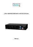
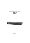
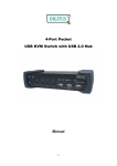
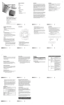
2-Port / 4-Port
KVM SWITCH
User’s Manual
Version 2.0 / 060914
Model Specifications
2-Port model
Audio model
PC Ports HDB-15
(VGA+USB+2 PS/2)
Audio (mic/speaker)
Console PS/2 Keyboard
PS/2 mouse
Video HDB-15
USB Keyboard
USB mouse
Audio (mic/speaker)
KCF-121
√
KCB-121
√
KCF-121A
√
√
KCB-121A
√
√
2
2
2
2
√
√
√
2
√
√
√
√
2
√
√
√
√
√
√
√
√
KCB-121
KCB-121A
KCF-121
KCF-121A
2/2
√
√
√
Model Specifications
4-Port model
Audio model
PC Ports HDB-15
(VGA+USB+2 PS/2)
Audio (mic/speaker)
Console PS/2 Keyboard
PS/2 mouse
Video HDB-15
USB Keyboard
USB mouse
Audio (mic/speaker)
KCF-141
√
KCB-141
√
KCF-141A
√
√
KCB-141A
√
√
4
4
4
4
√
√
√
4
√
√
√
√
4
√
√
√
√
√
√
√
√
KCB-141
KCB-141A
KCF-141
KCF-141A
3/3
√
√
√
1. Introduction
The 2-Port/4-Port KVM Switch are high quality and durable systems that will allow
you to control 2/4 host computers (or servers) by connecting to PS/2 or USB
connectors from one console (PS/2 / USB Mouse, PS/2 / USB Keyboard, and
Monitor).
1.1 Features
Controls 2 / 4 computers from a single console (Keyboard/Mouse) over either
PS/2 or USB connections
The PC ports support Windows, Linux, Mac OS9/OSX, Sun Microsystems.
Keyboard emulation on each un-selected PC to allow it to boot normally
without a keyboard error
Hot-swap support. All devices connected to the KVM switch can be added or
removed at any time without shutting the unit down.
Support 2 types of switching: (1) Hardware Push Button control, (2) Hot key
command control from PS/2 or USB keyboard.
Provide Auto-scan function to alternate video between computers in a preset
interval.
Provide LED display for PC status monitoring.
Supports VGA resolutions up to 2048 x 1536.
Provide Beeper during switching enabled.
Self powered through PS/2 and/or USB connection
Fully compliant with the USB 1.1/ 2.0 specification
1.2 Package Contents
The product you purchased should contain the following equipment and
accessories:
One 2-Port /4-Port KVM Switch unit
2/4 combo 4-in-1 cables
2/4 sets of speaker+microphone cables. ( with Audio models )
Product CD (with operation manual)
4/4
2. Specifications
2.1 General
Specification
Number Of Computers Controlled 2 / 4
PC Port Selection Method
Push Button and Hot-Key (PS/2 or USB Keyboard)
LEDs
Red for PC Selection
Green for PC On-Line ready
PC Connectors
Video
2 / 4 x HDB -15 female
( VGA+USB+PS/2 signal combined )
Console Ports
Speaker
2 / 4 audio female jacket (audio model)
Microphone
2 / 4 audio female jacket (audio model)
Keyboard
KCF models - PS/2 mini-DIN + USB A type
KCB models – PS/2 mini-DIN
Mouse
KCF models - PS/2 mini-DIN + USB A type
KCB models – PS/2 mini-DIN
Video
1 x HDB -15 female
Speaker
1 x audio female jacket (audio model)
Microphone
1 x audio female jacket (audio model)
Auto-Scan Interval
5 ~ 250 Seconds
DDC, DDC2 monitor
Yes (Max. Resolution: 2048x1536) @ 85Hz
Hot Swappable
Yes
Operating systems supported
Windows 98SE/ME/2000/XP/2003 Server, Linux
Mac OS9/OSX and Sun Micro System
Device driver
No Need
Power
By PS/2 and/or USB or External Power Adapter
Cable Length
6 feet
Dimensions (L X W X H)
2-Port : 14.0 x 8.5 x 4.5 cm
(5.5 x 3.3 x 1.7 inches)
4-Port : 21.5 x 8.8 x 4.5 cm
(8.5 x 3.4 x 1.7 inches)
Unit Weight
(1.80 Meter)
2-Port : 420~465 g
4-Port : 620~650 g
Housing material
Metal
Operating Temperature
32~ 122oF
Humidity
0%~80%RH
5/5
(0~ 50oC )
2.2 Front Panel and Rear Panel
The following figure illustrated 4-Port model with Audio and PS2 & USB console as
example:
Figure 2-1
Front Panel & Rear Panel
6/6
3. System Requirements
Console
A VGA, SVGA, Multisync monitor capable of the highest resolution
PS/2 and/or USB Keyboard/Mouse
Computers or Servers (PCs)
The following equipment must be equipped with each computer or server.
- A VGA, SVGA or Multisync card
- Type A USB port or PS/2 6 pin mini-DIN for Keyboard and Mouse
Cables
The KVM Switch must be used with specific combo 4-in-1 cables. To purchase
more cable sets, contact your dealer.
Figure 3-1 Combo 4-in-1 cable
7/7
4. Installation
LED Indicators:
LED Name
Selected
On-Line
On-Line
Color
State
Red
Green
Green
ON
ON
Blinking
Function
The PC port is selected.
An active PC is connected.
KVM is in auto-scan mode.
Reset Switch :
Press this push button switch to reset the KVM device. To push the switch, use a
ball-point pen or a small stick.
4.1 Installation
Precaution:
1. For users who want to connect PC over PS/2 interface, finish PS/2 connection
before turning on the PC. PC is unable to detect PS/2 devices if PS/2 is not
connected while booting.
2. When connecting Windows 98 PC, it is suggested to use PS/2 for the PC
connections, because Windows 98 does not support installation at first time
through USB HID installation driver.
3. Some old PCs can support USB ports during booting, but are required to open
BIOS USB setting first.
4. The KVM switch does not support the USB keyboard which has built-in USB
HUB.
5. The KVM switch can be powered by either PS/2 keyboard or USB connection.
For some laptops, the PS/2 or USB power might not be enough to support the
KVM switch and cause the KVM switch not working properly. Use external
power adapter with 5V/0.3A~1A for the KVM power in this case.
6.
For Windows 2000/2003/XP PC which is set to “need to be login with the
password” and connects to KVM switch only over USB, it is suggested to
complete the installation with KVM before logging out the windows. This will
let the PC detect USB HID device and install the driver automatically for next
booting.
8/8
Console connections:
Plug USB or PS/2 keyboard, USB or PS/2 mouse arbitrarily and VGA video into
the Console ports located on the front panel. A combination of USB mouse and
PS/2 keyboard or a combination of PS/2 mouse and USB keyboard are all
supported by the KVM Switch unit.
System connections:
Use KVM combo 4-in-1 cable (as shown in Figure 3-1) to connect an available
KVM’s PC port to a computer’s video and USB or PS/2 ports.
Improve monitor display quality:
If you are using LCD monitor connected to the KVM switch with Audio and feel the
display quality is not comfortable to you, you can apply monitor’s Auto-adjusting
function to improve the display quality.
9/9
This KVM Switch with specific combo cable provides three connecting methods.
1.
Plug Speaker, Microphone, USB, PS/2 ( keyboard/mouse) ports and VGA into
PCs at same time, recommended in priority. ( Figure 4-1 ).
Figure 4-1
Speaker, Microphone,PS/2 & USB and VGA connected at same time
2.
Plug only Speaker, Microphone, PS/2 (keyboard / mouse) ports and VGA into
PCs. ( Figure 4-2 )
Figure 4-2
Speaker, Microphone, PS/2 and VGA connected
10/10
3.
Plug only Speaker, Microphone, USB and VGA into PCs. ( Figure 4-3 ).
Figure 4-3
Speaker, Microphone, USB and VGA connected
5. Operations
The 2/4-Port KVM Switch has the ability to switch the keyboard, video, mouse,
audio, microphone simultaneously.
Note: When using Hot Key, the keys must be pressed within 5 seconds; otherwise
the Hot Key action is terminated.
5.1 Push Button on front panel
Figure 5-1
Push Button for PC Port Selection
Push the button directly to select the connected PC.
11/11
5.2 Hot-key operation ( Either PS/2 or USB Keyboard )
The hotkey command examples listed in following sections are based on the
4-Port models. The 2-Port models are equipped with the same design, but 2 PC
selections only.
Note: If your keyboard does not provide < Scroll Lock > button, use < Caps Lock
> or <Num Lock > as leading key instead.
5.2.1 Leading key Selection
Hot key commands:
[Ctrl] -> [Ctrl] -> [Caps Lock] -> [Enter] to change leading key to [Caps Lock]
[Ctrl] -> [Ctrl] -> [Num Lock] -> [Enter] to change leading key to [Num Lock]
[Ctrl] -> [Ctrl] -> [Scroll Lock] -> [Enter] to change leading key to [Scroll Lock]
Note: The default leading hotkey setting is [Scroll Lock]. After changing the
leading hotkey setting, the new setting will take effect immediately until the
KVM switch is powered off or reset.
5.2.2 PC Selection
Hot key commands:
[Scroll] -> [Scroll] -> [Enter] to select next higher PC port (not including Audio)
[Scroll] -> [Scroll] -> [→] to select next higher PC port (not including Audio)
[Scroll] -> [Scroll] -> [←] to select next lower PC port (not including Audio)
[Scroll] -> [Scroll] -> [ 1 ] -> [Enter] to select PC1 (not including Audio)
[Scroll] -> [Scroll] -> [ 2 ] -> [Enter] to select PC2 (not including Audio)
[Scroll] -> [Scroll] -> [ 3 ] -> [Enter] to select PC3 (not including Audio)
[Scroll] -> [Scroll] -> [ 4 ] -> [Enter] to select PC4 (not including Audio)
12/12
5.2.3 Auto-Scan Function
Hot key command:
[Scroll] -> [Scroll] -> [S] -> [Enter] to start Auto-scan operation
Under Auto-scan operation, you can press any key to stop Auto-scan operation.
Auto-scan function allows the KVM Switch alternates the connected PCs and
displays them on the console monitor. Each PC is displayed in a time interval in a
range of 5 ~ 250 seconds (The interval is adjustable) before switching to the next
PC. During Auto-scan operation, the KVM Switch will ignore mouse operation.
Pressing any key will stop the Auto-scan and the console monitor screen will jump
back to the original PC.
Adjustable scan time interval setting ( 5 ~ 250 sec. ) Hot key command:
[Scroll] -> [Scroll] -> [S] -> <5 ~250 > [Enter]
5.2.4 Beeper Enable
Hot key commands:
[Scroll] -> [Scroll] -> [B] -> [Enter] to disable Beeper
[Scroll] -> [Scroll] -> [B] -> [Enter] to enable Beeper
The Speaker/Beeper’s default setting is “Enable”. While the switching connections
are activated and Speaker/Beeper is in “Enable” status, the beeper has a short
beep.
13/13
5.3 Audio ( Speaker / Microphone ) Selection – only work with Audio model
5.3.1 (PC+Audio) Combination Selection
Hot key commands:
[Scroll] -> [Scroll] -> [F1] -> [Enter] to select PC1 with its Audio
[Scroll] -> [Scroll] -> [F2] -> [Enter] to select PC2 with its Audio
[Scroll] -> [Scroll] -> [F3] -> [Enter] to select PC3 with its Audio
[Scroll] -> [Scroll] -> [F4] -> [Enter] to select PC4 with its Audio
5.3.2 Audio Only ( Speaker + Microphone ) Selection
Hot key command:
[Scroll] -> [Scroll] -> [A] -> [Enter] to enable/disable Audio auto-switch mode
Note: One long beep – Audio auto-switch mode is disabled.
Three short beeps – Audio auto-switch mode is enabled.
Audio Auto-Switch Mode
When this mode is enabled, the PC KVM and the associated Audio are switched at
the same time. When disabled, only PC KVM is switched. This mode has default
setting - enabled. Audio means speaker and microphone signals.
Audio only selection hot key commands:
[Scroll] -> [Scroll] -> [A] -> [1] -> [Enter] to select PC1’s Audio only
[Scroll] -> [Scroll] -> [A] -> [2] -> [Enter] to select PC2’s Audio only
[Scroll] -> [Scroll] -> [A] -> [3] -> [Enter] to select PC3’s Audio only
[Scroll] -> [Scroll] -> [A] -> [4] -> [Enter] to select PC4’s Audio only
14/14
5.4 Hot-Key Definition Table
Step 1
Step 2
[Scroll] + [Scroll]
[1] + [ Enter ]
[2] + [ Enter ]
[3] + [ Enter ]
[4] + [ Enter ]
[ Enter ]
Function
[Scroll] + [Scroll]
[→]
[←]
[A] + [ Enter ]
[F1] + [ Enter ]
[F2] + [ Enter ]
[F3] + [ Enter ]
[F4] + [ Enter ]
Switch the active connection to PC 1
Switch the active connection to PC 2
Switch the active connection to PC 3
Switch the active connection to PC 4
Switch the active connection to next higher PC
Switch the active connection to next higher PC
Switch the active connection to next lower PC
Toggle disable/enable Audio auto-switch mode
Switch (PC+Audio) to PC 1
Switch (PC+Audio) to PC 2
Switch (PC+Audio) to PC 3
Switch (PC+Audio) to PC 4
[Scroll] + [Scroll]
[A] + [1] + [ Enter ]
Audio switching to PC1’s audio
[Scroll] + [Scroll]
[A] + [2] + [ Enter ]
Audio switching to PC2’s audio
[Scroll] + [Scroll]
[A] + [3] + [ Enter ]
Audio switching to PC3’s audio
[Scroll] + [Scroll]
[A] + [4] + [ Enter ]
Audio switching to PC4’s audio
[Scroll] + [Scroll]
[B] + [ Enter ]
Toggle disable/enable beeper
[Scroll] + [Scroll]
[S] + [ Enter ]
[S] + [5 -250 ] +
[ Enter ]
Toggle disable/enable Auto-Scan mode
[Scroll] + [Scroll]
[Scroll] + [Scroll]
[Scroll] + [Scroll]
[Scroll] + [Scroll]
[Scroll] + [Scroll]
[Scroll] + [Scroll]
[Scroll] + [Scroll]
[Scroll] + [Scroll]
[Scroll] + [Scroll]
[Scroll] + [Scroll]
[Scroll] + [Scroll]
Select the Auto-Scan interval from 5 to 250 Sec.
15/15
6. Sun Microsystems Function Key Emulation
There are 16 special functions provided on Sun Microsystems keyboard. The KVM
Switch can emulate those function keys on console’s PS/2 and USB keyboard.
The following table lists the key mapping. To activate any emulation on the PS/2 or
USB keyboard, press the LEFT Window KEY first (this key usually is located
between the left [Ctrl] key and left [Alt] key), then press the second associated key.
Sun Micro System Function Key
PS/2 (or USB) Keyboard
Stop
L_Win & L_Alt
Props
L_Win & L_Ctrl
Compose
L_Win & L_Shift
Front
L_Win & F1
Open
L_Win & F2
Find
L_Win & F3
Again
L_Win & F4
Undo
L_Win & F5
Copy
L_Win & F6
Paste
L_Win & F7
Cut
L_Win & F8
Help
L_Win & F11
Power
L_Win & F12
Mute
L_Win & 1
Volume Down
L_Win & 2
Volume UP
L_Win & 3
16/16
7. Troubleshooting
Configuration
General
KVM switch is powered by
connected PC.
PC connects to the KVM
over both PS/2 and USB.
PC connects to the KVM
over PS/2 only.
KVM in Auto-scan operation
Problem
Suggestion
-
Make sure all cables are properly and
reliably connected.
Short beep sound repeats. The problem could be caused by not
sufficient power supplied from the PC. Use
+5V DC power adapter for the KVM.
PC not working properly
Use USB connection only.
PC not working properly
Change to USB connection.
Mouse operation is ignored by the KVM in
Auto-scan mode. Stop Auto-scan
operation to operate your mouse.
PC connects to the KVM
PC failed to boot up due to Reset the PC BIOS or upgrade the BIOS
with a new one, which can accept USB
over USB.
keyboard error. Keyboard
keyboard in booting.
error message is shown on
the screen.
Old PC connects to the KVM “Keyboard not found error”
Old PC BIOS will check PS/2 keyboard
over USB only.
message appears when PC
while resuming from suspend mode.
resumes from suspend
Change USB connection to PS/2 to walk
mode.
around.
Use customized driver with The special keys or buttons If the USB mouse and keyboard support
PS/2 converter, use PS/2 converter with
USB mouse and keyboard to not working properly.
the USB mouse and keyboard. Then,
define special keys and
change USB connection to PS/2 to the
buttons. The PC connects to
KVM.
the KVM over USB only.
PC VGA to KVM distance
The rated maximum distance is 5 meters.
PC keyboard to KVM
distance
PC mouse to KVM distance
Mouse not working
-
The rated maximum distance is 3 meters.
-
The rated maximum distance is 3 meters.
17/17
Disclaimer
Information in this document is subject to change without notice. The manufacturer does not make any representations or
warranties (implied or otherwise) regarding the accuracy and completeness of this document and shall in no event be liable for
any loss of profit or any other commercial damage, including but not limited to special, incidental, consequential, or other
damages.
No part of this document may be reproduced or transmitted in any form by any means, electronic or mechanical, including
photocopying, recording or information recording and retrieval systems without the express written permission of the
manufacturer.
All brand names and product names used in this document are trademarks, or registered trademarks of their respective
holders.
FCC Statement
This device generates and uses radio frequency and may cause interference to radio and television reception if not installed
and used properly. This has been tested and found to comply with the limits of a Class B computing device in accordance with
the specifications in Part 15 of the FCC Rules. These specifications are designed to provide reasonable protection against such
interference in a residential installation. However, there is no guarantee that interference will not occur in a particular installation.
If this device does cause harmful interference to radio or television reception, which can be determined by plugging the device
in and out, the user can try to correct the interference by one or more of the following measures:
Reorient or relocate the receiving antenna.
Increase the separation between the device and receiver.
Connect the computer into an outlet on a circuit different from that to which the receiver is connected.
Consult the dealer or an experienced radio/TV technician for help.
CE NOTICE
Marking by the symbol
indicates compliance of this equipment to the EMC directive of the European Community.
Such marking is indicative that this equipment meets or exceeds the following technical standards:
EMC Class B
EN 50081-1/1992 : EN55022, EN61000-3-2, EN61000-3-3
EN 50082-1/1998 : EN61000-4-2, EN61000-4-3, EN61000-4-4, EN61000-4-5, EN61000-4-6, EN61000-4-8, EN61000-4-11
18/18