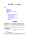
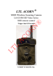
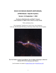
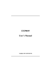
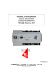
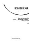
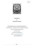
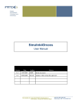
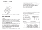
1
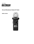
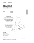
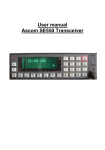
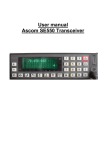
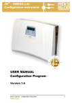
24GHz FMCW Radar User Manual
FMCW front-end transmits period liner triangle wave in frequency-time plane. It swept band B at time
T (slop k=+/-B/T). Return signal reflected by target has time delay td (td=2R/C) with Doppler
frequency fd. The coherent output, beat signal, is equal to fb=(2B/CT)R+/-fd. Back end detect fb by
DSP in +/-slop period, Range and velocity of target is tested with amplitude. Azimuth or elevation
angle could be obtained by mono-pulse antenna or beam forming technology. Mechanical scanning,
usually in azimuth direction, is used for wide scanning range. Radar data will generate radar map on
Host PC screen.
www.changxiangelec.com | 525 Chesterfield Lane, North Aurora, IL 60542 | Tel: 630 882 2623
Page 1
CONTENT
1.
Application Fields ………………………………….……………………… Page 3
2.
Basic Parts of 24GHz FMCW Sensor/Radar ………..……..….. Page 4
3.
24GHz FMCW Front End ………………………….…………………….. Page 5
4.
5.
6.
3-1
Photo and Draw of Front end -------------------------------Page 5
3-2
24GHz FMCW Radar Diagram Block -----------------------Page 6
3-3
TX Frequency Setup ------------------------------------------- Page 7
Front-end only User Manual ……………...……………..………… Page 8
4-1
Requirements List ----------------------------------------------Page 8
4-2
Setting Up the FMCW Front-end ---------------------------Page 8
4-3
Check front-end Works by Spectrum Analyzer -----------Page 8
Front-end With Back-end User Manual ………………..…..…. Page 9
5-1
Requirements ---------------------------------------------------Page 9
5-2
Setting Up the FMCW Sensor -------------------------------Page 9
24GHz FMCW Radar User Manual ……………………….......... Page 10
6-1
Requirement ----------------------------------------------------Page 10
6-2
Setting up the FMCW Radar --------------------------------Page 10
6-3
Operate FMCW Radar ----------------------------------------Page 11
6-4
Test Set and Record FMCW Radar Data ------------------Page 12
6-4-1 Outdoors Set ----------------------------------------Page 12
6-4-2 Indoor Set --------------------------------------------Page 12
6-4-3 Zoom for Outdoors Set ---------------------------Page 12
6-4-4 Function of Radar Map Operate Key -----------Page 13
6-4-5 Radar Data Format --------------------------------Page 14
7.
Typical 24GHz Radar Specification ………………..………..…... Page 16
www.changxiangelec.com | 525 Chesterfield Lane, North Aurora, IL 60542 | Tel: 630 882 2623
Page 2
1. Application Fields
This radar is typical used to detect vehicle with max distance 200m or detect human inside 50m.
The range resolution is 1 meter or less (design value is 0.75m). Attached Fig 1 is the test photo
for vehicle in 120meters. There is a big truck in 44 meter, but is at adjacent lane, which is at
least 4meter long. The radar map shows exactly 1target in 120m, and 2 targets in 44m and 47m.
The radar data will provide target or targets information as: Amplitude, Range, Velocity, Azimuth
angle by mono-pulse, and time gap for next time see target again with distance at that time.
The last 10 pages radar data is stored in DSP memory and can be send out thru Ethernet cable.
The host computer with radar map code will operate radar and display radar map.
Fig 1
Typical Application of 24GHz FMCW Radar
www.changxiangelec.com | 525 Chesterfield Lane, North Aurora, IL 60542 | Tel: 630 882 2623
Page 3
2. Basic Parts of 24GHz FMCW Sensor/Radar
24GHz FMCW radar is formed by front-end, back-end, connect cable, and optional host PC.
Front-end has dual antennas and transceiver. Transceiver has FMCW TX, which is controlled by
back-end to generate FMCW signals. It shares 1 antenna with 1 RX CH. There are 2 RXs to get
mono-pulse function in Azimuth plane. Back-end has TX signal controller to generate linearity
FMCW signal. It has 2 CH ADC to process mono-pulse signal if digit format. Back-end output
radar data thru USB interface to main DSP (as FMCW sensor) or to host computer (as FMCW
radar). Host computer must have radar map code to run the radar. Figure 2 is the photo for
main parts. Table 1 lists main parts and key function.
Fig 2
Name
Front-end
Back-end
Cable
Host PC
Main sub unit
Patch array antenna for
TX and RX
24GHz Transceiver with
2CH RX
TX controller
Main Parts
Key function
Transmit 24.125GH, 200MHz band FMCW signal to
target, receive return signal
TX send 8dBm FMCW signal controlled by DSP
2CH RX send mix 1.25MHz beat signal to back-end
Send FMCE refer to TX, get accuracy frequency, band
and linearity
ADC and FFT convert for DSP
Radar data ready to host PC
RX DSP unite
Interface
DDS to TX
2CH RX to ADC
Ethernet interface to Radar data for main DSP or host PC for map
host computer
Radar data and map
Operate radar
Table 1 FMCW Sensor/Radar Basic Parts and Key Function List
www.changxiangelec.com | 525 Chesterfield Lane, North Aurora, IL 60542 | Tel: 630 882 2623
Page 4
3. 24GHz FMCW Front End
3-1: Photo and Draw of Front end
Fig 3 is the photo and design draw with outlet size of 24GHz FMCW front end. The unit is in inch.
Fig 3-1 Antenna Photo
Fig 3-3
Fig 3-2 Transceiver Photo
Antenna and Transceiver Design draw and outlet size in inch
www.changxiangelec.com | 525 Chesterfield Lane, North Aurora, IL 60542 | Tel: 630 882 2623
Page 5
3-2: 24GHz FMCW Radar Diagram Block
Fig 4
24GHz FMCW Radar Diagram Block
www.changxiangelec.com | 525 Chesterfield Lane, North Aurora, IL 60542 | Tel: 630 882 2623
Page 6
3-3: TX Frequency Setup
As shown in Diagram Block of 24GHz FMCW radar, micro controller inside the front end, and
DSP core of back-end sets TX parameters.
TX parameters are center frequency fo, swept band B, and modulation frequency Fm.
The TX of 24 GHz front end is a 24GHz VCO locked by a synthesizer, which is operated by a micro
controller. A 16 prescaler is used to divide 24GHz frequency down to 1.5GHz so that synthesizer
can process. The maximum Phase Detector Frequency Fpdf of synthesizer is 250MHz. The
minimum divider number for VCO frequency is 24. The DSP can provide any frequency band
between 10~210MHz with 0.05% linearity FMCW signals in 10KHz stepper frequency.
The fo and B from PLL set maybe different with design value. The order of set rule are: 1) let
tolerance of B as small as better. Most set can reach tolerance is zero. 2) let tolerance of fo
smallest, 3) let Fpdf as high as better for lower phase noise issue.
Fo and B can be adjusted by the requirement from customer to customer. Typical fo range is
from 23.4GHz to 24.2GHz. The value of B is from 10MHz up to 1GHz. (maximum of fo is less
than 23.8GHz when 1GHz band required). Anyway, they are not changed after ELEC pre-set.
The waveform of swept band is triangle wave in frequency-time plane. Then the modulation
frequency Fm is default as 1KHz. It can be adjusted as 0.25, 0.5, 1, 2, 4, 5, 8, and 10KHz if
customer wants upgrade. The limitation of parameter set is maximum sample frequency of ADC
is 2.5MHz each CH for 2 ADC CHs. So that maximum fb [fb=(4BFm/C)Rmax + fdmax] should be
less than 1.25MHz.
TX of 24GHz FMCW radar default set are: B=200.00MHz, fo=24.12533GHz, Fpdf=60.3125MHz.
Then DSP provides 180.19~181.69MHz FMCW signals to TX of front end. The maximum detect
range is 200m. The Doppler frequency is 161Hz for 1m/sec. Then max range return frequency is
533.3KHz. Maximum Doppler frequency is less than 10KHz (if maximum relative velocity is
140mph). They are inside the limitation 1.25MHz.
www.changxiangelec.com | 525 Chesterfield Lane, North Aurora, IL 60542 | Tel: 630 882 2623
Page 7
4. Front-end only User Manual
4-1: Requirements List
Standard
product
Radar Front-end ELEC™ 24GHz FMCW Front-end
Cable
DB9-to-Banana Plugs cable (for 5V, 3V, -5V)
3 SMA to SMA Cables (For Fm, fbr, and fba)
Customer have
Power Supply
Capability to generate 5V/500mA, 3V/500mA, and –5V/200mA
Function
Capability to generate any frequency range inside 10~210MHz
Generator
Triangle wave in F-T plane, -9dBm/50ohm, 0.05% linearity, 1 or
10KHz stepper.
Measurement
Spectrum analyzer (this manual recommended)
or customer PC which has FMCW DSP function
4-2: Setting Up the FMCW Front-end
1) Connecting the Radar front-end with the DB9 side of the cable.
2) Connecting the Banana plugs of the cable with power supply and provide 5V/500mA,
3V/500mA and –5V/200mA DC to radar front-end.
3) Connecting SMA cable between Fm and the Function generator. Set function generator
fstart=180.19MHz, fstop=181.69MHz. and select triangle wave form. (Or the value
agreement before delivers). The power is –8+/-1dBm for 50ohm load.
4) Connecting the Spectrum analyzer with SMA cables named the “FBA” or “FBR” port of
the cable.
5) Turn on DC supplies. Note 5V DC supply should be the first one for turn. It is the best
turn all 3 DC supplies at the same time.
4-3: Check front-end Works by Spectrum Analyzer
The frequency of fb signal is equal to (4BFm/C)R+/-fd. Where fd=2Vd/(C/fc). C is light velocity,
3x10^8m/sec. Vd is target velocity; R is the distance of the target. At 24GHz carrier, fd=161Hz
when target radial velocity is 1m/s. It is much smaller than range frequency. Spectrum Analyzes
test is just for static target (because spectrum analyzer has no FMCW process function. It only
has DAC and FFT function). So the return frequency is 2.667KHz per meter. When B=200MHz,
Fm=1KHz. In other words, read spectrum analyzer output frequency, then divided by 2.667, it is
the range of the target.
The amplitude should be larger than –70dBm (march ELEC back-end sensitivity). The signal to
noise ration is 10dB or higher.
If customer has FMCW DSP, or host PC to process FMCW radar signal, the connection is referred
to the follow section.
www.changxiangelec.com | 525 Chesterfield Lane, North Aurora, IL 60542 | Tel: 630 882 2623
Page 8
5. Front-end With Back-end User Manual
5-1: Requirements
Front-end work with ELEC DSP back-end is the FMCW sensor. It output radar data thru USB
interface to host DSP or host PC. The radar data contact all information of targets. The detail
radar data parameters are (Amplitude, Range, Velocity, Azimuth angle, …)j, j=1, 2,……N. the
maximum N is inter number of Rmax/range resolution as long as target amplitude is larger than
Amplitude threshold (typical is –70dBm). For example, Rmax=200m, dR (range resolution) is 1m,
radar maximum radar data will include 200 targets, each target has at least 4 parameters. Radar
data are digit store in memory inside DSP or host PC.
To use the FMCW sensor, requirements parts are listed
Fundament parts
Radar Front-end
Radar Back-end
Cables
Optional parts
Power Supplies
Host computer
ELEC™ 24GHz FMCW front-end 24G-T1R2-WS-WB2 (refer fig
2)
ELEC™ DSP board
DB9-to-DB9 cable, Ethernet cable. 3 SMA to SMA
Capability to generate 9V/600mA, 5V/500mA, -5V/200mA,
3V/500mA
Check radar data
5-2: Setting up the FMCW Sensor
1) Connecting the Radar front-end and back-end with the DB9-to-DB9 cable. And 3 SMA
Cables
2) Connecting the back-end DSP box Banana plugs to DC power supplies 9V, 5V, 3V, and –
5V.
3) Connecting the back-end DSP box USB interface to host computer
4) Turn on all DC supplies. If not turn on in the same time. Turn on 5V before turn on 3V.
5) Check radar data on host computer
www.changxiangelec.com | 525 Chesterfield Lane, North Aurora, IL 60542 | Tel: 630 882 2623
Page 9
6. 24GHz FMCW Radar User Manual
6-1: Requirement
FMCW Radar sensor only output radar data. It is hard for operator to operate the radar, or see
target by eye. With the help of host computer and radar map code, FMCW radar brown host PC
screen and key broad to run the radar, and recorder all radar data. Follow is the list parts for
FMCW radar
Fundament parts
Radar Front-end
Radar Back-end
DSP User CD
Cables
Optional parts
Power Supplies
Host PC
Operating System
Processor
Memory
Software
ELEC™ 24GHz FMCW front-end : 24G-T1R2-WS-WB2 (refer fig
2)
ELEC™ DSP board
ELEC FMCW radar map code
DB9-to-DB9 cable, Ethernet cable. 3 SMA to SMA
Capability to generate 9V/600mA, 5V/60mA, -5.5V/30mA,
5V/60mA dc
Windows® XP
Pentium® 4 2.0G or better
2GB or better
Matlab® 7.0 (ELEC just provide trial version in 45days)
6-2: Setting Up the FMCW Radar
Setup Matlab 7.0
1) Copy X:\ code\Matlab\tcp_udp_ip to C:\MATLAB7\work.
2) Double click icon MATLAB7 on desktop to launch matlab.
3) Click … and set Current Directory to C:\MATLAB7\work\tcp_udp_ip
4) Type radar in Command Window, and press ENTER to launch radar map program.
Setup Web
5) Connect DSP board with computer using Ethernet cable.
6) Right click My Network Places and select Properties in order to open Network
Connections.
7) Right click Local Area Connection and select Properties.
8) Select Internet Protocol(TCP/IP) -> Properties.
On the Internet Protocol(TCP/IP) Properties page, select Use the following IP address,
and set the IP address as 192.168.1.77, set Subnet mask as 255.255.255.0. And then
click OK to save the configuration.
www.changxiangelec.com | 525 Chesterfield Lane, North Aurora, IL 60542 | Tel: 630 882 2623
Page 10
Setup FMCW Radar
Connect the Radar front-end and back-end with the DB9-to-DB9 cable. And 3 SMA Cables
Connecting the back-end DSP box Banana plugs to DC power supplies 9V, 5V, 3V, and –5V.
Connecting the back-end DSP box USB interface to host computer by USB cable
Turn on all DC supplies. If not turn on in the same time, turn on 5V before turn on 3V
6-3: Operate FMCW Radar
1) After DSP board and front-end is turned on, open the internet browser on computer and
type http://192.168.1.11/index.html, then Radar Operate Parameter Window appears for
user to adjust radar parameters, as Fig 5 shows.
Fig 5 Radar Operate Parameter Window
2) For radar data, Rmin=0m, Rmax=200m, and Aref=-70dBm. As mentioned before, radar data
will recorder all targets which amplitude larger than –70dBm. And range is from 0 to 200m.
Because of the range resolution is 1m, so that maximum targets in radar data is 200. Radar
map will zoom range window by reselect Rmain and Rmax, as long as 0 <= Rmin <Rmax <=
200m. Beside of it, radar map will filter less important target by reselect Aref. (-70dBm <=
Arfef <-10dBm). Input radar parameters then click “START” button to save the configuration
and turn the radar front-end on.
3) Launch Matlab® 7.0. Set folder “tcp_udp_ip” as Current Directory, then type command:
radar to run radar map program.
4) When the radar map program comes out (as Fig 6 shows), the 24GHz FMCW radar system
will be ready to use.
www.changxiangelec.com | 525 Chesterfield Lane, North Aurora, IL 60542 | Tel: 630 882 2623
Page 11
6-4: Test Set and Record FMCW Radar Data
6-4-1: Outdoors Set
Test Photo shown in Fig 1 sets Aref=-60dBm. Rmin=0m, and Rmax=150m. This set is for ELEC
outdoor test field, which maximum range is 150m.
6-4-2: Indoor Set
Test photo shown in Fig 6 sets Aref=-35dBm, Rmin=0m, and Rmax=15m. This set is for ELEC
indoor test field, which maximum range is 13.5m when door closed. The target is set at 6m.
6-4-3: Zoom for outdoors Set
Test photo shown in Fig 7, zoom outdoor test field for Rmin=0m, Rmax=50m, and Aref=-60dBm.
One person is stand at 35meters and left offset of antenna beam. A truck is parked at 44meter
and right offset of antenna beam. Mono-pulse radar map is selected to show photo clearly.
Fig 6
Radar Map and Operate Key
www.changxiangelec.com | 525 Chesterfield Lane, North Aurora, IL 60542 | Tel: 630 882 2623
Page 12
6-4-4: Function of Radar map Operate Key
There are 4 operate keys on Radar display screen. They are: (Fig 7 has clear picture)
1) Exit key: press exit will end radar map display.
2) Enable Save key: Press enable save key will save radar data in text-format to file named
runfmcw.
Operator
can
fid
this
file
in
follow
patch
C:\Matlab7\work\tcp_udp_ip\runfmcw.
The radar data will be saved page by page as long as memory size is larger enough or exit
key is pressed.
3) Clear Key: press Clear will clear all data stored in runfmacw file. Operator must rename
runfmcw if they want keep old test data.
4) Upload Page Data Key. Press this key code will record radar data and stored them to file
named
fmcw.
Operator
can
fid
this
file
in
follow
patch
C:\Matlab7\work\tcp_udp_ip\fmcw. This file only store last 15 pages of radar data. And
fresh them when page number is increased. It is required to press stop key show in Fig 5.
(Note, Fig 5 RADAR GO in red color indicates start, after press start it changes to stop,
which means radar is run and waiting stop.) Then read last 15 page of radar data in
fmcw file.
Fig 7 Person at 35m with Truck at 44~48m, both offset antenna maximum beam line
www.changxiangelec.com | 525 Chesterfield Lane, North Aurora, IL 60542 | Tel: 630 882 2623
Page 13
6-4-5: Radar Data Format
ELEC FMCW radar code generates Fm signal for TX. DSP finish ADC convert and FFT twice for
each Fm period. The rule to select target is compare FFT signals amplitude with Aref. When
Fm=1KHz, DSP analyzes return signal every 0.5ms. So it gets positive slop and negative slop
frequency in 1ms, and future convert them as range, and velocity with amplitude parameters.
Because DSP process 2CHs, compare their phase get mono-pulse angle. Default is in Elevation
plan. For Azimuth mono-pulse radar, just process EL parameter as Az parameter. ELEC FMCW
code still has ability to drive stepper motor for mechanical scan. Default is in Az plane. So Az
plane has 3 choice, fixed beam (with or without mono-pulse), 360 scan, and sector scan.
Anyway, Code sees target/targets 1 time in 1 Fm period. Code will see target Nc times and
average them together as radar-data-cell in Nc of Fm period. Usually Nc>=5. For mechanical
scan, each Az angle, typical is stepper motor stepper, 1.8 degrees, has 1 radar-data-cell. 1
complete scan generates radar-data. So there are 200 radar-data-cells in one page of radar-data.
The number of radar-data-cell is scan range/1.8. The code set 50ms as upgrade time for no scan
model. In other words, Nc=50 when Fm=1KHz. So that radar-data-cell is equal to 1 page of
radar-data only for no scan model.
Fig 8
Radar Data Format
www.changxiangelec.com | 525 Chesterfield Lane, North Aurora, IL 60542 | Tel: 630 882 2623
Page 14
One typical radar data is shown in Fig.8. It gives 2 pages of no scan radar-data. Each page tells
how many target radar detect. Let just analyzes page 1. It list the page number in 1st row . Then
give the Range from 8.3m to 194.9m in 2nd row, follow the Pred Range in 3rd row, which means
the predict range next time (after 50ms) radar see them again. It cones from current range and
velocity Vel at row 4. Most of them is static target (-5cm/s, -9cm/s, 0.6m/s, 9cm/s, 11cm/s and –
12cm/s). Part of them has velocity at (2.8m/s, -1.8m/s, -4.8m/s, and 1.6m/s). The 5th row gives
target amplitude from –40dBm to –65dBm, all of them are larger than –70dBm. The 6th row is
Az angle. Because no scan, all of them is at 0 degree. The 7th row is El angle. The last row is time
predict when target touch radar. The negative means target is moving away from radar. The
danger is the target moving forward radar. Target 6 will touch radar after 28 seconds.
www.changxiangelec.com | 525 Chesterfield Lane, North Aurora, IL 60542 | Tel: 630 882 2623
Page 15
7. Typical 24GHz Radar Specification
Sign
Unit
Value Range
Pt
Fc
B
dBm
GHz
MHz
Modulation
Waveform
Linearity
Antenna Type
Antenna Gain
Azimuth 3db beam
Elevation 3dB beam
Side lobe
Isolation
Fm
KHz
L
%
G
Az
El
Aside
Iso
dB
degree
degree
dB
dBc
Receiver Noise
Dynamic range
Size
Weight
DC supply
Interface
N
DR
LxWxH
V/I
dB
dB
inch
g
V/A
6~8
24.125+/-0.0005
200
up to 1GHz
1~10
triangle wave
0.05
Dual patch array
23~24
10.4+/-0.8
8.2+/-0.5
16~25
>50
10~20
3~4
60~80
5.9x3.8x0.52
<300
5V/0.5A, 3V/0.5A, -5V/0.2A
DB9, and SMA
Fm [F(t)]
fsamp
KHz
MHz
MHz
0.25, 0.5, 1, 2, 4, 5, 8, 10
Any range between 10~210
2.5/1.25/0.625
128/256/512
Fixed beam
360 deg scan
+/-(18, 36, 45, 90) sector
1KHz default
0.05% linearity
2CH
512 default
Fixed beam default
Fs
Ss
Hz
deg
0.1,0.25,0.5,1,2,2.5,4,5
1.8
16 for fixed beam
4 for each 1.8 deg stepper
1Hz default
Front End
Transmit power
Carrier frequency
Swept Band
Back End
Fm frequency
Freq/time function
DAC sample Freq
FFT bit
Scan Model
Scan rate
Scan stepper
Target number
Interface
Recommend
Fm must be F(t)
default
If license approved
1KHz default
Fm=F(t)
In Azimuth-direction
RX only
TR share 1 antenna
With 12 bit ADC
Current rate is 1A
Just for radar map
DB9 with SMA
Ethernet to PC
DC connector
Typical Radar Spec
Max range
Rmax
m
Human 30~50
Car: 100~200
Min range
Range resolution
Max velocity
Velocity resolution
Rmin
dR
Vmax
dV
m
m
M/s
M/s
0~Rmax-1
1m (B=200MHz)
60
1
0.2m (B=1GHz)
Optional to 0.2~0.5
www.changxiangelec.com | 525 Chesterfield Lane, North Aurora, IL 60542 | Tel: 630 882 2623
Page 16