1
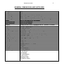
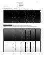
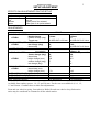
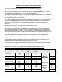
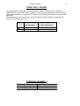
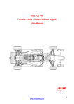
DALLARA F300 FORMULA 3/2000 USER MANUAL Dallara Automobili 2 FOREWORD Dallara Automobili is happy with the choice you made buying our Formula 3 car and wishes you the very best in racing it. For any question, advice or idea you might have, please don’t hesitate to contact us. Dallara Automobili: Via Provinciale 33 – 43040 VARANO MELEGARI – PR – ITALY Telephone Fax +39-0525-550711 +39-0525-53478 (design) (technical assistance) (business) (commercial) Mr Ferdinando Concari Mr Jos Claes Mrs Caterina Dallara Mr Alberto Lecordetti Email [email protected] Email [email protected] Email [email protected] Email [email protected] Dallara has its own web site www.dallara.it where you can find useful information about our company, our people and our factory. DALLARA PARTS DISTRIBUTORS JAPAN Le Mans Company Contact Telephone Fax UNITED KINGDOM Contact Telephone Fax Email Le Mans Building 3215 Hiroo – Shibuya-ku - Tokyo – JAPAN Mrs. Katsuhisa Homma/Shiro Matsunaga +81-3-3400-5086 (+81-550 840-100) +81-3-3486-0820 (+81-550-885-552) AMT Motorsport Aldershot, Hampshire Mr. Martin Stone +44-0-1252 333 294 +44-0-1252 321 661 [email protected] GERMANY Contact Telephone Fax Miss Katrin Eichstaedt +49 2331 954 275 +49 2331 961 842 FRANCE Contact Telephone Fax ASM / Phillipe +33 386 660 036 +33 386 660 929 Dallara Automobili 3 CONTENTS CAR INFO SET-UP SUSPENSION 4-5 6-7 FRONT REAR RIDE HEIGHT 8-12 12-14 15 DIFFERENTIAL DAMPERS AERODYNAMICS 16-17 18-19 20-24 UPRIGHT & HUB ASSEMBLY SYSTEMS OIL BRAKES FUEL ELECTRICS EXTINGHUISHER GEARBOX 25-26 27 28 29 30-33 34 35 SAFETY AND UTILITY NOTES TIGHTENING TORQUES CONVERSION TABLE 36-37 38 39 GENERAL AGREEMENT AND WARRANTY CERTIFICATES (& FIA DOCUMENTS) 40 41- Dallara Automobili TOP AND SIDE VIEW F300 4 Dallara Automobili 5 GENERAL DIMENSIONS AND SUPPLIERS Wheelbase Front Track Rear Track Overall height Overall width Overall length Weight Front suspension Rear suspension Chassis Bodywork Composites Castings Gearbox Gears and differential Springs Dampers Fuel cell Extinguisher system Steering wheel Steering release system Coolers Filters Rims Brake system Battery Seat belt Installed engines 2678mm 1500mm 1430mm 915 mm (from ground to top of roll hop) 1750 mm (wide front suspension) 4060 mm (front endplate to rearmost edge of rear wing) 540 Kg (including driver and ballast) push-rod monodamper push-rod twin damper Carbon and KEVLAR™ sandwich with AL / NOMEX h/comb Glass fibre prepreg with NOMEX honeycomb HEXCEL-HERCULES AGUSTA/FLABO DALLARA casing, five ratios and reverse gear HEWLAND EIBACH 36 mm ID KONI 2812-140 (bump and rebound adjustable) PREMIER – FT3 SPA design (electrical operated) OMP – 270 mm OD SPA design BEHR FIAAM SPEEDLINE 9” front – 10.5” rear BREMBO FIAMM TRW-SABELT Fiat, Alfa, BMW Novamotor Honda Mugen Opel Spiess Renault Sodemo Toyota Tom’s Mitsubishi HKS VW Bertil’s (USA). Dallara Automobili 6 SET-UP TIRE INFORMATION Tire dimensions depend on tyre pressure, rim width and camber angle. The stiffness values are based on the recommended inflating pressure (hot tyres). FRONT TIRE Specification Free radius (mm) Loaded radius (mm) Vertical stiffness (Kg/mm) Hot tire pressure (bar) REAR TIRE Specification Free radius (mm) Loaded radius (mm) Vertical stiffness (Kg/mm) Hot tire pressure (bar) Avon 180/550-13 277.5 272 21.0 1.5 Bridgestone 180/550-13 277.2 271.5 14.4 1.5 Michelin 20/54-13 272.3 267.8 20.7 1.55 Pirelli 200/530-13 266.3 261.5 17.1 1.5 Yokohama 180/50-13 278.0 273.2 17.0 1.6 250/570-13 287.0 281.3 22.8 1.65 240/570-13 286.5 279.0 16.7 1.5 24/57-13 289.1 284.0 21.8 1.6 250/575-13 289.4 282.0 17.2 1.55 240/45-13 288.0 281.0 17.8 1.55 SUGGESTED SETUP The set-ups consider the complete car with the driver seated, ready to race. The front anti roll setting pre-load is ‘double stiffness’ pre-load, for details look at the FARB pages. FRONT Ride height (mm) Camber (deg) Toe (deg) (total two wheels) Springs (lb/in) Vertical Pre-load (mm) Avon 15 2°45’ 20’ OUT 800 8 Bridge 15 3°15’ 10’ OUT 700 6 Michelin 15 3°45’ 20’ OUT 800 8 Pirelli 15 4° 20’ OUT 800 5 Yokohama 15 3°15’ 20’OUT 700 5 Solid spacer (mm) Push rod length (mm) Roll centre setting Roll bar setting Roll pre-load (notches) REAR 6 682.5 STD <<>><< 9 6 682.5 STD <<>><< 9 6 689.5 STD <<>><< 9 6 689.5 STD <<>><< 9 6 682.5 STD <<>><<>> 0 Ride height (mm) Camber (deg) Toe (deg) (total two wheels) Springs (lb/in) Pre-load (mm) 34 2°00’ 10’ IN 900 0 34 2°15’ 20’ IN 800 0 34 3°30’ 0 900 0 34 3°15’ 0 900 0 34 2°45’ 10’IN 800 0 Push rod length (mm) Roll centre setting Roll bar Differential setting 572 STD 21 OD 60/80#4 572 STD 24 OD 60/80#6 572 STD 24 OD 60/80#4 572 STD 24 OD 60/80#6 572 STD 24 OD 60/80#4 Dallara Automobili 7 SETUP ADJUSTMENT EFFECTS ON ADJUSTMENTS ON THE SET-UP Positive change in: Height Toe Camber Castor means: car rises toe-out upper part of rim outward lower part of rim points ahead ADJUSTMENTS FRONT REAR 4.30mm 2’ M1.25R+24/”L=2.31mm 6.52mm 14’ M1.25R+24/''L=2.31mm 36’ 24/” 17’ 26’ 24/'' -0.8 -7' 2' 1°25’ M1.25R+24/”L=2.31mm 15’ 0.5mm = 18’ 20° brakecaliper=14.5° -38’ 20/'' -0.2 4' -4' 2 1.78 0.91 1.56 -Tyre dependent 2 2.42 1.21 -1.77 Tyre dependent PUSHROD ADJUSTER Height change Camber change (deg) Thread step TOE ADJUSTER (PER WHEEL) +1TURN toe change (deg) thread step CAMBER SPACER +1mm toe variation CASTOR ADJUSTER Castor change (deg) thread step height change (mm) +1TURN camber change (deg) toe change (deg) +1TURN SPRING PLATFORM +1TURN thread step (mm) height change (mm) WHEEL/SPRING RATIO (vertical) WHEEL/BELLEVILLE RATIO (lateral) WHEEL/DROP LINK RATIO (roll) ROLL CENTRE HEIGHT Available front camber spacers: 1.0, 1.5 and 2.0 mm. For the rear are available 0.8, 1.0, 1.2, 1.5 and 2.0mm. Combine these to make fine adjustments. Front and rear wheel to spring, front wheel to Belleville and rear wheel to drop link motion ratios may be considered as constant for all the wheel motion. Dallara Automobili 8 FRONT SUSPENSION VERTICAL or SPRING PRELOAD In a non pre-load condition, as long as the damper is not fully extended, turning the platform C raises the ride height and lowers slightly the pressure inside the damper. When the damper gets fully extended, turning-on the platform C puts vertical spring pre-load on the car. We advise though, not to proceed this way, because some dampers (including Koni) should not be used fully extended. Therefore we advise to use the droop-stop ‘A’. Remind that there is some pre-load in each damper. With a Koni damper this pre-load is about 30kg. This pre-load depends on damper type, settings and internal gas pressure. Pre-load is the force that has to be applied on the spring to start to modify its length with respect to the static value. To set the on car pre-load, put the car with the driver seated on the set-up floor. Unscrew the droop-stop A to contact the opposite bolt B. Now turn platform C to set the pre-load. As the platform thread step is 2 mm, the pre-load P = Ks x t x 2 P = pre-load in kg Ks = spring stiffness in kg/mm (spring stiffness in Lb/in) / 56 = spring stiffness in kg/mm T = number of platform C turns 2 = mm / turn (for Koni) SETTING THE ‘ON CAR PRE-LOAD’ Mount the damper-spring combination with the platform C just in contact with the spring. Mount damper-spring combination on the car and put the car with the driver seated on the set-up floor. Make the car bounce a few times to settle down. Screw the droop-stop A into the rocker, away from touching bolt B. Adjust ride height with the pushrod adjusters to the desired setting. Bring droop-stop A in contact with bolt B. Turn platform C until desired pre-load force is achieved. (P = Ks x tTx 2) Dallara Automobili 9 FRONT ANTI ROLL AND PRE-LOAD There are 3 different ways of setting the front anti-roll Belleville washers. Mount a stack configuration and turn the platforms just in contact with the stack. This way there is no pre-load on the stack and the roll stiffness is the nominal stack stiffness. For example: the configuration <<>><< gives 761kg/mm stiffness. When both platforms get turned on a few notches the system is preloaded. The roll stiffness under this pre-load is double the nominal stiffness. When the rocker passes the pre-load the stiffness gets back to the nominal. For example: >><<>> + 5 notches is for 0.5mm of lateral movement 761x2=1522kg/mm stiff. When both platforms get turned on a few notches and locked up with the two extra locknuts the system is infinite stiff, this means there is no lateral movement as long as the force doesn’t overcome the pre-load. Once the pre-load passed, the stiffness gets back to nominal. Both pre-load settings (2 and 3) generally help for sharper turn-in. Soft no pre-load settings (1) can make the tyres last longer and make the car easier to drive. Over the pre-load, the stiffness gets back to the nominal stiffness. The driver may prefer some pre-load in certain conditions (turn-in…) and wish to overcome the pre-load in some other conditions (mid corner, curbs…). Set accurately the transition point of ‘pre-load / no pre-load’ since the consequently stiffness variation is sudden and reflects immediately on the cars’ balance and behaviour. You can combine different stacks in series to obtain a progressive load / displacement characteristic. Total length of the combined stack should never be more than 28mm. Pay attention to: -The clearance between the platform and the rocker (B) should not be more than 6.5mm when platform just touches the Belleville stack, with no pre-load. -For any Belleville stack, in running condition, rocker lateral displacement and the chosen pre-load must never reach the "Maximum Deflection" (see Table below), to avoid a sudden lateral locking of the rocker. BELLEVILLE STACK CONFIGURATIONS (Belleville thickness 2.0mm) Stack configuration <<<<>>>> <<<>>> <<<>>><<< <<>><< <<>><<>> <<>><<>><< <>< <><> <><>< <><><> <><><>< Nominal stiffness kg/mm Stack length mm Maximum deflection mm 2504 1796 1197 761 571 457 362 272 218 181 155 17.50 13.50 20.25 14.25 19.00 23.75 8.25 11.00 13.75 16.50 19.25 1.12 1.12 1.69 1.69 2.25 2.81 1.69 2.25 2.81 3.37 3.93 Maximum notches → respect maximum notches when using preload configurations → 8 8 12 12 17 22 14 17 22 26 28 Dallara Automobili 10 SETTING THE PRE-LOAD DOUBLE STIFFNESS PRE-LOAD • Mount the stack you want to use and turn the platform until contact with the Belleville stack • Adjust by turning the platforms until distance A is the same on both sides • Check distance B to be under than 6.5mm, if it’s more, replace adjustment spacer • Mark this platform position as the “zero pre-load” notch • Turn both left and right platforms the amount of notches to set the desired pre-load. One turn of platform is 15 notches corresponding to 1.5mm displacement (1 notch = 0.1mm) INFINITE STIFFNESS PRE-LOAD • Set the pre-load as described for the double stiffness procedure here above • Mount nut D in contact with the platform • Tighten counter nut E against nut D Dallara Automobili 11 FRONT ROLL CENTER Moving the spacer underneath or above the lower wishbone spherical joint changes the height of the front roll centre. When choosing "low roll centre" configuration, push-rod length has to be shortened by 1.4 register turns (8 faces of the adjuster) to keep the car at the same ride height. When adjusting the roll centre height, there will also be a slight change in camber gain in function of vertical wheel travel. OPTION Std Low Roll centre height Camber change static ride height for 10mm wheel travel X -12.5 mm 5’ 3’ STEERING ASSEMBLY Pinion primitive diameter Static steering ratio Ackermann [%] 15.71 mm 12.6 steering wheel/wheel 28.5 Dallara Automobili 12 MEASURING CASTOR FRONT When the car is flat (front ride height equals rear) and the front upright inclination is 1.80°, castor angle is 10.5°. With different front to rear ride heights, castor angle changes because of the pitch angle of the car. For instance, with 15 mm front and 40mm rear ride height, measured at wheel axis, (wheelbase is 2678 mm) the pitch angle is 0.53° as: Pitch angle (40-15)/2678 = 1 / tan 0.53° castor angle: 10.5° - 0.53° = 9.97° REAR The rear wheel castor (not relevant because the wheel is not steered) can be checked using the brake-calliper mounting platforms. When the car is flat (front ride height equals rear) and the measured angle is 20° the castor is 14.5°. The pitch angle must be added because the castor is rearward. Dallara Automobili REAR SUSPENSION REAR SUSPENSION ROLL CENTER AND ANTISQUAT SETTING OPTION Roll centre height Camber change Antisquat static ride height for 10mm wheel travel % std 21’ 48 A-1 -15 17’ 48 B-2* +15 25’ 48 C-1 std 21’ 60 D-1* -15 17’ 60 E-2* +5 22’ 30 F-1 -10 18’ 30 G-2 Option D-1 and E-2 alter caster angle. To obtain std value shorten by 2 turns the ‘castor’ uniball. Option B-2 needs special bracket for front top mounting (available at Dallara) REAR ANTIROLL BAR STIFFNESS 13 Dallara Automobili 14 F300 has a rear anti-roll bar with two 75mm long adjustable blades. 40mm diameter ARB is the stiffest available, this can be milt down to any softer ARB. The two digits in this table represent the blade positions: 1=full soft, 5=full hard. Stiffness in kg/mm. OD 14 mm 16 mm 19 mm 21 mm 24 mm STD 28 mm 1-1 22.6 33.4 50.6 61.1 73.8 85.1 1-5 24.8 38.6 63.3 80.7 104.3 128.6 2-5 25.1 39.2 65.1 83.6 109.2 136.1 3-5 25.9 41.2 70.9 93.4 126.7 164.3 4-5 27.0 44.0 79.5 108.9 156.8 218.9 5-5 27.6 45.5 84.6 118.6 177.9 262.2 REAR SUSPENSION ROCKER REPLACEMENT The rear rocker spins around a steel pivot ‘A’ fitted onto the gearbox casing by stud B, fixed with LOCTITE 242. The following procedure shows the disassembly of the rocker and the pivot A. Contact DALLARA customers’ service to get the tools E and F. • • • • • Unscrew nut C. The tightening torque to fit it back is 3.5 Kgm; Take off the top cap and the rocker; Unscrew nut D with a long 14mm tubular dowel. The tightening torque to fit it back is 5.5 Kgm; Fit extractor F around the pivot’s outer flange, screwing in bolt E, and remove the pivot Remove stud B with the proper tool. The stud is fitted with Loctite in its insert. When removing the stud, heat up the stud’s thread to break the Loctite with a heat gun up to 140 C°. RIDE HEIGHT CHECK AND REFERENCES Dallara Automobili 15 Ride height is fundamental for setting and changing the aerodynamic performance of the car. It might be difficult to measure it directly, so we provide alternative references. The example shows front ride height 15mm and rear 34mm (at wheel axis). With 2678mm wheelbase, pitch angle is 0.40°. Calculation: (34 – 15) / 2678 = inv. tan x → x = 0.40° (The two round platforms on top of the tub to measure front ride height at front axis are 50mm behind the axis when using the long wheelbase front suspension) Measuring front ride height: A flat surface (skid) about 310 mm behind the wheel axis and 50 mm behind the skid leading edge. You can measure its distance from ground as 17 - (tan0.40°x310)=15mm Measuring rear ride height: Two machined areas, at 327.5 mm from car bottom, on the gearbox at wheel axle line. You can measure their distance from the ground as 361.5 – 327.5 = 34mm height. Under the flat bottom, 50mm ahead of the start of the diffuser and 313mm ahead of the rear wheel axis, you can measure and calculate the floor distance from the ground as following: measured 32mm + (tan0.40°x313) = 34mm REAR RIDE HEIGHT 34mm FRONT RIDE HEIGHT 15mm POWER FLOW DIFFERENTIAL Dallara Automobili 16 WORKING PRINCIPLE AND SETUP This differential (“diff”) is designed with versatility as its major asset. Many parameters will lead you to the required setting. A car with good grip and low power may require a completely different arrangement than that for a high power/low grip car. The working principles of powerflow differentials: Ten friction plates within the diff, six connected to the side gears, four to the diff casing, control the amount of differential action available. The amount of limited slip depends only on the frictional resistance between these ten plates. Four factors contribute in defining this frictional resistance (see figure next page): 1. The bevel gears thrust apart as soon as the car moves. This is a feature of bevel gears and is not adjustable; 2. The ramp angle on the side gear ring influences the amount of the driving force on the diff round that is directed sideways and onto the plates. E.g., on the power/drive side ramp, 45 degrees transmits less force sideways than 30 degrees. Likewise, on the brake/coast side ramp, an 80 degrees angle will transmit little or no force while 45 degrees does. Check to see which different side rear rings are available for each model of diff. 60°/80° is normally fitted as standard; 3. The pre-load with which they are assembled to start. In each diff there is a pre-load spacer that looks like one of the B plates, but thicker. Depending on diff model, it is either the first or last component assembled into the diff casing. Its thickness dictates to what degree the plates are pre-loaded / forced against each other. The pre-load is set and checked on each diff by holding one side gear still, via a dummy output shaft held in a vice, and by turning the other with a torque wrench. If the measured resistance is deemed too high, the spacer is ground down until the desired figure is achieved (usually between 5 to 20 lbs ft). The figure should be checked periodically as it tends to reduce as the diff runs, meanwhile a new A, slightly thicker spacer will allow re-setting; 4. The final and easiest adjustment is the re-arrangement of the contact order of the plates. The arrangement 1, with a plates succession A, B, A, B, A, has the maximum number of working friction faces and is the standard one. It gives the maximum resisting torque. The arrangement 3 has the minimum of working friction faces and gives the minimum resisting torque. By swapping from arrangement 1 to 3, the resisting torque approximately halves. AVAILABLE RAMP ANGLES Power side 30° 60° 80° 45° 45° Brake side 60° 80° 80° 80° 45° Dallara Automobili DIFFERENTIAL LAY-OUT • Make sure the plate arrangement is always equal on left and right-hand side. • Side gear ring, diff end plate, diff wall and pre-load spacer all act as “B” plates • Bigger ramp angle transmits less thrust onto plates than smaller one. 17 Dallara Automobili 18 DAMPERS DIMENSIONS & GENERAL INFORMATION • Standard dampers are KONI 2812-140. Front and rear dampers have identical valving, the same full-extended length and identical installation parts. Damper assembly dimensions are: full open length full closed length (front) (rear) stroke (front) (rear) • • • mm 335 297 291 38 44 The difference in stroke and full closed length is due to the 6mm Teflon spacer on front damper to prevent the rocker to lock. If you use different dampers check that max stroke is not more than 38 mm. The standard Koni damper has about 30kg of pre-load, due to the internal gas pressure. Dallara, on request, delivers installation kits for PENSKE and QUANTUM dampers. Eibach dampers can be installed using standard mountings. Dallara Automobili 19 DAMPERS DIAGRAM The Koni dampers are adjustable both in bump and rebound by acting on the adjuster wheels marked B (for bump adjustment) and R (for rebound adjustment) on the damper top. Each adjuster wheel has eight different positions. KONI 2812/140 Figure shows force/velocity graphs for full soft and full stiff settings. Dallara Automobili FRONT WING FRONT WING CONFIGURATIONS FRONT WING SIDEPLATE HOLES 20 Dallara Automobili 21 REAR WING REAR WING PROFILES REAR WING CONFIGURATION LDF LOW DOWNFORCE MDF MID DOWNFORCE REAR WING SIDEPLATE HOLES HDF HIGH DOWNFORCE Dallara Automobili 22 FRONT AND REAR WING SIDEPLATE TABLE • Front flap angle is measured on top of the flap front and inside the Gurney ‘corner’, as shown on page 20. • Correspondence between holes and incidence angle is just indicative, because wing angle is also function of front and rear ride heights. • The machined side-plates allow 1 deg step adjustment. FRONT FLAP A 8° 15° 22° 29° 1 2 3 4 B 9° 16° 23° 30° C 10° 17° 24° 31° D 11° 18° 25° 32° E 12° 19° 26° 33° F 13° 20° 27° 34° REAR TOP 1 2 3 4 A 0° 6° 12° 18° B 1° 7° 13° 19° C 2° 8° 14° 20° D 3° 9° 15° 21° E 4° 10° 16° 22° F 5° 11° 17° 23° G 14° 21° 28° 35° Dallara Automobili 23 POLAR DIAGRAM Every point corresponds to a downforce level listed below. F300 POLAR DIAGRAM 2,200 DOWNFORCE (CzT) 2,000 1,800 1,600 1,400 1,200 0,600 0,650 0,700 0,750 0,800 DRAG (CxT) REAR FRONT LDF= Low Down Force (single small top) MDF= Medium DF (twin small top) HDF= High DF (small and mid combined top) REAR CFG 1 2 3 4 5 6 7 8 9 10 11 12 TOP TYPE NONE LDF MDF MDF MDF MDF HDF HDF HDF HDF HDF HDF MF= Medium Flap (small flap) SF= Standard Flap EF= Extended Flap (standard plus extension) FRONT SETTING 2 6 10 14 18 11 14 17 17 20 23 LOWER 1 5 5 5 5 5 5 5 5 7 7 7 FLAP TYPE NONE MF MF MF MF MF SF SF SF EF EF EF ALL NUMBERS ARE DEGREES SETTING 9 14 18 22 26 16 18 20 20 22 24 MAIN PLANE -0.5 -0.5 -0.5 -0.5 -0.5 -0.5 -0.5 -0.5 -0.5 -0.5 -0.5 -0.5 CFG 1 2 3 4 5 6 7 8 9 10 11 12 Dallara Automobili 24 AERODYNAMIC information • • • • • Front wing main-plane and rear lower wing, are set relative to the chassis reference plane. The optimum setting for most of the setting range is for front wing main-plane –0.5°, and for the rear lower wing + 5°. Any chassis rake angle will alter this setting. Front flap inclination is intended to be the angle, relative to the chassis reference plane, measured between front of the flap, on top and rearmost trailing edge (without any Gurney). Rear top wing assembly inclination is intended to be the angle, relative to the chassis reference plane, measured between front of the flap, on top and rearmost trailing edge. Any chassis rake angle will alter this setting. Front and rear ride height settings are fundamental to the aerodynamic balance and ultimate performance of the car. Pay attention to the changes between the static setting and the dynamic values on track. Downforce CFG Part Min Suggested Max Suggested Hole Incidence Hole Incidence Front Flap A1 2o C4 25o o Rear top LDF Wing C1 0 B2 5o Rear top MDF/HDF Wing A1 0o A4 / F4 18°/23° How to balance 1° FR flap variation by changing the rear wing, RR ride height or FR ride height? RR TOP→ LDF MF 2 holes RR top 1.5mm lower RR height 1mm higher FR height FR FR FLAP MDF MF SF 1 hole RR top 1.5mm lower RR height 1mm higher FR height 2 holes RR top 3.5mm lower RR height 2mm higher FR height HDF SF EF 1 hole RR top 2.5mm lower RR height 1.5mm higher FR height 2 holes RR top 2.5mm lower RR height 1.5mm higher FR height MF: Medium Flap; SF: Standard Flap (as ’99); EF: Extended Flap COOLING ADJUSTMENT Depending on air temperature and engine optimum water temperature you can set the cooling capacity of the radiators. Efficiency increases by sealing any eventual leakage in the inlet ducts to the radiators. Dallara Automobili 25 FRONT UPRIGHT SAFETY NOTE We advice to regularly check the lower stud on the front uprights, which could show little cracks difficult to detect by men’s eye. Use penetrating liquid to check these studs after each accident and according the following schedule: Check after 3000km, 4000km and 5000km, after 5000km each 500km or after each race meeting or test day. HUB ASSEMBLY The following procedure tells to change front and rear hub bearings Removal of bearing a) Remove spigot by removing the 6 screws A; b) Push off drive flange by using two 6x1 screws set on thread B; c) Remove seeger C; d) Press off bearing from the upright; e) Push off retainer by means of two 6x1 screws set on thread B. Replacement of bearing a) Press wheel bearing into the upright; b) Fit seeger C; c) Press the retainer into the wheel bearing; d) Place spigot in position on the drive flange, fit A screws, washers and nuts and tighten to 41 Nm (Caution: this value is for 12K screws only). Wheel stud removal a) To reduce resistance to Loctite, heat wheel stud and retainer to 180°C; b) Remove pin D, remove wheel stud. Wheel stud replacement a) Remove pin D; b) Clean and degrease retainer thread and wheel stud; c) Spray degreaser to threaded area of retainer and wheel stud. Caution: Don’t use petrol; d) Apply LOCTITE 638 to wheel stud thread; e) Screw wheel stud into retainer and tighten to 245 Nm by forcing on head T; f) Drill wheel stud and insert pin D. Bearing assembly into hub replacement Warm the hub to 100°C; Fit the bearing assembly Dallara Automobili HUB ASSEMBLY FRONT HUB REAR HUB 26 Dallara Automobili 27 SYSTEMS ENGINE OIL SYSTEM • • • • We recommend keeping the oil level at 115 mm from the oil cap, measured with running engine. Less oil may cause cavitation and so air to get into the oil circuit. More oil may cause power loss. Typically you would need 4.5 litres to fit in the oil tank, or 5.0 when using an oil cooler. GEARBOX OIL Typically you would need 1.2 litres to properly run the gearbox and the differential. Dallara Automobili BRAKE SYSTEM BREMBO BRAKE CALIPER ASSEMBLY 28 Dallara Automobili FUEL SYSTEM • • F300 features twin electrical-submerged fuel pumps as a redundant caution in case one pump fails. The driver can switch between the two pumps from the cockpit. OPEL-Spiess installation has a specific high-pressure pump. 29 Dallara Automobili ELECTRICAL SYSTEM Analogical dashboard wiring 30 Dallara Automobili PI and BOSCH dashboard wiring 31 Dallara Automobili MARELLI dashboard wiring 32 Dallara Automobili STANDARD ENGINE WIRING 33 Dallara Automobili 34 EXTINGUISHER SYSTEM LAYOUT DETAILS The SPA Fire Fighter system is an electrically triggered Halon or foam spray fire extinguisher system. The system uses actuators to operate the valves located on the pressurised container, containing the extinguishing liquid. These are triggered remotely using a battery powered ‘power pack’. In order to guarantee reliability the actuators are of military specifications. The system/battery test electronics are integrated into the remote power pack. Connectors on the firing heads are also of military grade and use two contacts per lead to guarantee the best connections. Actuators are designed either to operate individually, or connected in series if two heads are used. TESTING The power pack electronics can test the continuity of the electrical wiring, and provides a high current pulse test on the battery, to ensure system integrity before use. The battery test electronics do not excessively drain the battery during this test. The tests are carried out using a three-way switch on the power pack. Since the system is only as good as the battery that powers it and the integrity of the wiring and its connections, the tests should be performed before each race. To check the battery, press and hold up the power pack switch. Every 2 seconds you’ll see a YELLOW light flash. If the light flashes very dimly the battery should be replaced. In doubt change the battery. To check the wiring continuity, ensure that the power pack switch is on “SYSTEM INACTIVE” to ensure that the extinguisher is not fired. Press the internal firing button and check that the RED light comes on. Press the external firing button and check that this also makes the RED light comes on. CARES Ensure that the electric ‘command’ cables are not laying next to or in the same loom as the car battery power cables or ignition cables. Ideally, all cables should lie next to the chassis (earth); Ensure that all plugs exposed to water spray are protected with rubber boots; If tubing is to be removed, push orange collet in. While holding in the collet, pull out the tube; Avoid any cable to run over sharp edges without protection; Do not fix the cables next to or onto any surface likely to exceed 200 °C; Do not turn the firing heads when the system is activated. Dallara Automobili 35 GEARBOX GEARBOX BEARINGS AND TORQUES For ease of maintenance and replacement you find in this drawing the standard fitted bearings in the gearbox and the tightening torques we suggest for the primary and secondary shaft nuts. Dallara Automobili 36 SAFETY AND UTILITY NOTICES In case of anomalies, contact immediately Dallara. SAFETY NOTICES STUD INSTALLATION AND REMOVAL It is very important to take an extreme care when removing and substituting the studs. Typically use: Loctite 270 (soft Loctite) for suspension brackets, brake calipers Loctite 242 (hard Loctite) for chassis, gearbox, bell-housing, roll hop Most of these studs are loctited and do require a proper installation procedure to follow - Clean the hole from dust, debris - Drive a screw tap to remove machining residuals - Clean the hole with compressed air - Pre assemble the stud without Loctite and remove - Clean the hole again with a degreaser and dry with compressed air - Coat the hole with Loctite - Install the stud - Tight the stud with the recommended tightening torque, you can do so by using a pair of nuts locked against each other. TRANSMISSION: To prevent the drive-shaft bolts from loosing, fit them with LOCTITE 242; FIRE SYSTEM: Take good care to the fire extinguisher: F399 models have electrically operated activation with small explosive charge. Notice to all the team crew for improper handling. AERODYNAMICS: It is forbidden to extract from mid downforce rear wing assembly the small profile and to use it for the rear low downforce configuration because they are differently reinforced. Buy the specific part. When running the car with a rear ride height of 45mm or more, please, check the height of the wing endplate. Total height cannot exceed 900mm. STEERING: Steering rack side tie rod ends must be absolutely replaced in case of crash. FUEL SYSTEM: Dallara, on request, can deliver quick release adapter for the fuel line connector CLUTCH: When using a thicker than F3 typical AP twin-plate metal clutch (i.e. carbon clutch…), please check that the clutch piston can move backwards enough to release the clutch completely. You can shorten the clutch piston spacer by turning off the required amount. WISHBONES: Never lift up the car, taking the middle of the wishbones. Never sit or stand on the wishbones. Dallara Automobili 37 SUSPENSION • • • • • • • Check pin to inner hub tightening both for front and rear upright assembly. You can notice if the locknut came loose by observing relative displacement of two red notches on locknut and on spigot. Check every 1000 Km lower pin locknut of front hub to prevent coming loose. Check the front upright lower stud on cracks after 3000km, 4000km and 5000km, after 5000km check them every 500km or after each race meeting or test day. After any accident, check alignment of front and rear pushrod and of their respective adjusters. Wishbones are treated with PARCO-LUBRITE. Clean the surface with acetone before inspection. Check periodically the K-nuts, which fixes the blades of rear antiroll bar to the drop links: they shouldn’t come loose. Ball joint A, used in front lower and rear lower wishbones, must be fitted with sharp side in contact with seeger B, as shown in following sketch. Dallara Automobili 38 TIGHTENING TORQUES The table lists some suggested tightening torques. For additional security use LOCTITE 242 or 243. Tightening torques: Bevel gear nuts Lay-shaft / main-shaft nuts Final drive bolts Brake disc bolt Brake caliper studs Wheel nut Wheel stud Damper end-stroke spacer Wheel driver columns Nut 7 × 1 (see hub assembly) Bolt 8.8 (see hub assembly) Bolt 12K (see hub assembly) Rocker cap nut Rocker stud nut 10-32 UNF ‘K’ nut 1 /4 UNF ‘K’ nut 5 /16 UNF ‘K’ nut 3 /8 UNF ‘K’ nut Nm 330 198 73 7 50 165 245 65 50 17 25 39 34 54 3 15 30 45 Kgm 33.5 20.2 7.5 0.7 5.1 17.0 25.0 6.6 5.1 1.7 2.5 4 3.5 5.5 0.3 1.5 3.0 4.6 lbs ft 250 150 55 5 38 125 185 49 38 13 19 29 25 40 2 9 18 37 Dallara Automobili 39 SWG & CONVERSION TABLE This table provides conversion from SWG (Std Wire Gage) to metric units for sheet-metal thickness SWG Metric [mm] 8 4.064 10 3.251 12 2.642 14 2.032 16 1.626 18 1.219 20 0.914 CONVERSION TABLE Length 1 inch=25.4 mm 1 foot=304.8 mm=12 in 1 yard=914.4 mm=3 ft 1 mile=5280 ft=1.60934 km Volume 1 cubic inch (c.i.)=16.387 cubic centimetres Pressure 1 psi=0.0716 bar 1 millimeter=0.03937 in 1 centimeter=0.3937 in 1 meter=39.37 in 1 kilometer=0.62137 miles 1 cubic centimeter=0.061 cubic inch 1 liter=1000 cc=61.0255 cubic inch 1 kg/cm2=1.019 bar 1 bar=105 Pa=0.1MPa 1 bar=13.95 psi Weight 1 ounce (oz)=28.35 grams 1 Kg=1000 grams = 2.205 lb 1 pound (lb.)=16 ounces=453.592 grams Speed 1 MPH=1.467 feet per second 1 mph=0.62137 kilometres per hour 1 kilometre per hour=1.60934 mph 1 IPS (in/s)=25.4 mm/s 1 mm/s=0.039 IPS Specific weight Water=1 kg/l Mineral Oil=0.903 Kg/l Gasoline=0.74 Kg/l Useful formulas Engine displacement=0.7854 × bore × bore × stroke × no. of cylinders British horsepower (BHP)= RPM × torque (lbs ft)/5250 MPH=RPM × tire diameter (in)/(gear ratio × 336) Km/h = RPM × tire diameter (mm)/(gear ratio × 5308) Lap speed (MPH) =track length (miles) ×3600/lap time (seconds) Lap speed (km/h) = track length (Km) × 3600/lap time (s) Average speed (MPH) =track length (miles) ×3600 × no. of laps/total time (seconds) Average speed (km/h) =track length (Km) ×3600 × no. of laps/total time (seconds) Dallara Automobili 40 GENERAL AGREEMENT AND WARRANTY Motor racing is not covered by warranty due to the intentional choice of drivers to race in a dangerous environment DALLARA indicates that under normal operating conditions a new car would not show failure in structural components before it has completed around 25000 Km. This holds true if necessary maintenance and checks are provided and if the car had no previous incidents. DALLARA is not responsible for incorrect chassis repairs, if made outside its factory or in centres not recognised by FIA. Chassis should be checked for structural failure not later than two years after delivery from DALLARA factory, and after each major accident. After first check or after any major accident it is mandatory to check the chassis every year in a centre recognised by FIA authority. DALLARA is not responsible for damage caused by non-genuine spare parts. Under maintenance, following parts should be replaced after 25000 Km or two-years use: wiring loom; starter motor; steering column steering rack and tie-rods brake pedal; brake disc bell; wheel bearings; suspension arms and spherical joints; engine installation parts; drive-shafts; wings and rear wing supporting plates; We firmly remind you that Main roll over hoop, Monocoque and Front nose-box (crushable structure) are FIA approved and cannot be modified by unauthorised personnel for whatever reason. Any change to these parts is sufficient reason for disqualification. Dallara Automobili FUEL SYSTEM LAYOUT 41 Dallara Automobili 42