1
Preface, Contents
Part 1: User information
SIMATIC
ET 200B
Distributed I/O Station
Manual
System Overview
1
Technical Description
2
Mechanical and Electrical
Installation
3
Configuration and
Parameterization
4
Status and Error Diagnostics
5
Part 2: Reference information
General Technical Specifications
6
Digital Modules
7
Analog Modules
8
Appendices
EWA 4NEB 812 6089-02c
Type Files and GSD Files
A
Configuration Telegram
B
Parameterization Telegram
C
Configuring with
COM ET 200 V4.x
D
Analog Modules and Old Type
Files
E
Order Numbers
F
Glossary, Index
Edition 04
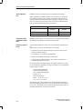
Safety Guidelines
!
!
!
This manual contains notices which you should observe to ensure your own personal safety, as
well as to protect the product and connected equipment. These notices are highlighted in the
manual by a warning triangle and are marked as follows according to the level of danger:
Danger
indicates that death, severe personal injury or substantial property damage will result if proper
precautions are not taken.
Warning
indicates that death, severe personal injury or substantial property damage can result if proper
precautions are not taken.
Caution
indicates that minor personal injury or property damage can result if proper precautions are not taken.
Note
draws your attention to particularly important information on the product, handling the product, or
to a particular part of the documentation.
Qualified Personnel
The device/system may only be set up and operated in conjunction with this manual.
Only qualified personnel should be allowed to install and work on this equipment. Qualified
persons are defined as persons who are authorized to commission, to ground, and to tag circuits,
equipment, and systems in accordance with established safety practices and standards.
Correct Usage
!
Note the following:
Warning
This device and its components may only be used for the applications described in the catalog or the
technical description, and only in connection with devices or components from other manufacturers
which have been approved or recommended by Siemens.
This product can only function correctly and safely if it is transported, stored, set up, and installed
correctly, and operated and maintained as recommended.
Trademarks
SIMATIC and SINEC are registered trademarks of SIEMENS AG.
Some of the other designations used in these documents are also registered trademarks; the owner’s rights may be violated if they are used be third parties for their own purposes.
Copyright Siemens AG 1995 All rights reserved
Disclaimer of Liability
The reproduction, transmission or use of this document or its
contents is not permitted without express written authority.
Offenders will be liable for damages. All rights, including rights
created by patent grant or registration of a utility model or design, are
reserved.
We have checked the contents of this manual for agreement with the
hardware and software described. Since deviations cannot be precluded entirely, we cannot guarantee full agreement. However, the
data in this manual are reviewed regularly and any necessary corrections included in subsequent editions. Suggestions for improvement are welcomed.
Siemens AG
Automation Group
Industrial Automation Systems
P.O. Box 4848, D-90327 Nuremberg
Siemens Aktiengesellschaft
ii
Technical data subject to change.
Siemens AG 1995
Order No. 6ES5 998-4ET21
ET 200B Distributed I/O Station
EWA 4NEB 812 6089 02c
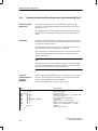
Preface
Purpose of the
Manual
The information contained in this manual will allow you:
To install, wire and start up the ET 200B distributed I/O station.
To find module characteristics and technical specifications quickly and
easily.
Contents of the
Manual
Scope of the
Manual
The following explains the structure of the contents of the manual:
What is the ET 200B?
Chap. 1
Which control and display
elements does the ET 200B have?
Chap. 2
How is the ET 200B installed?
Chap. 3
How do I configure
and parameterize the ET 200B?
Chap. 4
Faults?
Chap. 5
Technical Specifications?
Chap. 6, 7, 8
Which type files do I need?
Appendix A
How are configuration and
parameterization telegrams structured?
Appendix B, C
This manual describes all the ET 200B modules which can be accessed with
the PROFIBUS-DP bus protocol. These ET 200B modules all have order
numbers starting with 6ES7 (see Section F.1).
This manual is valid for operation of the ET 200B with:
IM 308-B master interface module and COM ET 200 V4.x
IM 308-C master interface module and COM ET 200 WINDOWS
S7/M7-DP master with PROFIBUS-DP interface and STEP 7
other PROFIBUS-DP masters from Siemens and other vendors.
Electronic Manuals
You can also order the documentation for the ET 200B distributed I/O station
as an electronic manual on CD-ROM.
Other Requisite
Manuals
In addition to this manual, you will also need the manual for the DP master
used (see Appendix F.2).
ET 200B Distributed I/O Station
EWA 4NEB 812 6089-02c
iii
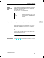
Preface
Organizational
Conventions
The following organizational conventions are used in this manual to make it
easier for you to find specific information:
At the front of the manual is a complete table of contents, together with a
list of all the figures and tables contained in the manual.
The left-hand column of each page in the individual chapters has headings to help you find information more quickly.
The Appendix is followed by a glossary containing definitions of the most
important technical terms used in the manual.
At the end of the manual is a detailed index which you can use to refer to
specific sections.
Standards
The ET200B distributed I/O station is based on the PROFIBUS standard
(EN 50170, Part 1) and the PROFIBUS-DP standard (EN 50170, Part 3).
Courses
Our ”KO-ET 200” workshop is the ideal way to get to know the ET 200 distributed I/O system.
If you would like more information, please contact your regional Training
Center or the following address:
Product Marketing for SIMATIC, SINEC and COROS
AUT 951
Frau Lades
Postfach 4848
D-90327 Nürnberg
Tel.: +49 (911) 895-3154
Fax: +49 (911) 895-5021
Queries
Please direct all technical queries to your Siemens contact partner in the office responsible for your area. You can look up the addresses in the manuals
for the CPUs, for example in the ”Siemens Worldwide” appendix of the
manual S7-300 Programmable Controller Hardware and Installation, in catalogs and in CompuServe (go autforum).
You may prefer to use our hotline support; the number to dial is
+49 (911) 895-7000 (fax 7001).
If you need type files or GSD files, the modem number to dial is
+49 (911) 737972.
If you have any questions or comments on this manual, please complete the
suggestions form and return it to us. You will find this form at the back of the
manual.
iv
ET 200B Distributed I/O Station
EWA 4NEB 812 6089-02c
Contents
1
2
3
4
5
System Overview
1.1
What is the ET 200 Distributed I/O System? . . . . . . . . . . . . . . . . . . . . . . . . .
1-2
1.2
1.2.1
1.2.2
What is the ET 200B? . . . . . . . . . . . . . . . . . . . . . . . . . . . . . . . . . . . . . . . . . . . .
Terminal Block . . . . . . . . . . . . . . . . . . . . . . . . . . . . . . . . . . . . . . . . . . . . . . . . . . .
Electronics Block . . . . . . . . . . . . . . . . . . . . . . . . . . . . . . . . . . . . . . . . . . . . . . . . .
1-3
1-5
1-6
Technical Description
2.1
Design of the Terminal Block . . . . . . . . . . . . . . . . . . . . . . . . . . . . . . . . . . . . . .
2-2
2.2
Design of the Electronics Block . . . . . . . . . . . . . . . . . . . . . . . . . . . . . . . . . . . .
2-4
Mechanical and Electrical Installation
3.1
Installing and Setting the Terminal Block . . . . . . . . . . . . . . . . . . . . . . . . . . . .
3-2
3.2
Installing the Electronics Block . . . . . . . . . . . . . . . . . . . . . . . . . . . . . . . . . . . . .
3-12
3.3
Dismantling the Terminal Block and the Electronics Block . . . . . . . . . . . . .
3-14
3.4
3.4.1
3.4.2
Electrical Installation . . . . . . . . . . . . . . . . . . . . . . . . . . . . . . . . . . . . . . . . . . . . . .
Grounded Configuration . . . . . . . . . . . . . . . . . . . . . . . . . . . . . . . . . . . . . . . . . .
Ungrounded Configuration . . . . . . . . . . . . . . . . . . . . . . . . . . . . . . . . . . . . . . . .
3-16
3-17
3-20
3.5
Wiring the Terminal Block . . . . . . . . . . . . . . . . . . . . . . . . . . . . . . . . . . . . . . . . .
3-22
3.6
Wiring the Bus Interface . . . . . . . . . . . . . . . . . . . . . . . . . . . . . . . . . . . . . . . . . .
3-26
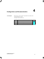
Configuration and Parameterization
4.1
Configuration Options . . . . . . . . . . . . . . . . . . . . . . . . . . . . . . . . . . . . . . . . . . . .
4-2
4.2
Requirements for Configuration . . . . . . . . . . . . . . . . . . . . . . . . . . . . . . . . . . . .
4-3
4.3
Where to Find the Requisite Information? . . . . . . . . . . . . . . . . . . . . . . . . . . .
4-5
Status and Error Diagnostics
5.1
Possible Response on Startup . . . . . . . . . . . . . . . . . . . . . . . . . . . . . . . . . . . . .
5-2
5.2
Status and Error Indication by LEDs . . . . . . . . . . . . . . . . . . . . . . . . . . . . . . . .
5-3
5.3
5.3.1
5.3.2
Slave Diagnostics . . . . . . . . . . . . . . . . . . . . . . . . . . . . . . . . . . . . . . . . . . . . . . . .
General Information on Slave Diagnostics, Operation with IM 308-C . . . .
General Information on Slave Diagnostics, Operation with S7/M7
DP Masters (STEP 7) or Other PROFIBUS-DP Masters . . . . . . . . . . . . . . .
Structure of Slave Diagnostics . . . . . . . . . . . . . . . . . . . . . . . . . . . . . . . . . . . . .
Structure of Station Status 1 to 3 . . . . . . . . . . . . . . . . . . . . . . . . . . . . . . . . . . .
Structure of the Master Station Number and the Manufacturer ID . . . . . . .
Structure of Device-Related Diagnostics (Digital ET 200B) . . . . . . . . . . . . .
Structure of ID-related Diagnostics (Analog ET 200B) . . . . . . . . . . . . . . . . .
Structure of Device-Related Diagnostics (Analog ET 200B) . . . . . . . . . . . .
5-5
5-6
5.3.3
5.3.4
5.3.5
5.3.6
5.3.7
5.3.8
ET 200B Distributed I/O Station
EWA 4NEB 812 6089-02c
5-8
5-9
5-11
5-13
5-14
5-16
5-18
v
Contents
6
General Technical Specifications
7
Digital Modules
7.1
Digital Modules . . . . . . . . . . . . . . . . . . . . . . . . . . . . . . . . . . . . . . . . . . . . . . . . . .
7-2
7.2
7.2.1
7.2.2
7.2.3
7.2.4
7.2.5
7.2.6
7.2.7
7.2.8
7.2.9
Terminal Blocks . . . . . . . . . . . . . . . . . . . . . . . . . . . . . . . . . . . . . . . . . . . . . . . . . .
Terminal Block TB1/DC (6ES7 193-0CA10-0XA0) . . . . . . . . . . . . . . . . . . . .
Terminal Block TB1-4/DC (6ES7 193-0CA20-0XA0) . . . . . . . . . . . . . . . . . .
Terminal Block TB3/DC (6ES7 193-0CA30-0XA0) . . . . . . . . . . . . . . . . . . . .
Terminal Block TB2/DC (6ES7 193-0CB10-0XA0) . . . . . . . . . . . . . . . . . . . .
Terminal Block TB2-4/DC (6ES7 193-0CB20-0XA0) . . . . . . . . . . . . . . . . . .
Terminal Block TB4/DC (6ES7 193-0CB30-0XA0) . . . . . . . . . . . . . . . . . . . .
Terminal Block TB4M/DC (6ES7 193-0CE30-0XA0) . . . . . . . . . . . . . . . . . .
Terminal Block TB6/AC (6ES7 193-0CC10-0XA0) . . . . . . . . . . . . . . . . . . . .
Terminal Block and Bus Connector . . . . . . . . . . . . . . . . . . . . . . . . . . . . . . . . .
7-4
7-5
7-6
7-7
7-8
7-9
7-10
7-11
7-12
7-13
7.3
7.3.1
7.3.2
Electronics Blocks . . . . . . . . . . . . . . . . . . . . . . . . . . . . . . . . . . . . . . . . . . . . . . . .
Electronics Block ET 200B-16DI (6ES7 131-0BH00-0XB0) . . . . . . . . . . . .
Electronics Blocks ET 200B-32DI (6ES7 131-0BL00-0XB0) and
ET 200B-32DI 0.2ms (6ES7 131-0BL10-0XB0) . . . . . . . . . . . . . . . . . . . . . .
Electronics Block ET 200B-16DO (6ES7 132-0BH01-0XB0) . . . . . . . . . . .
Electronics Block ET 200B-16DO/2A (6ES7 132-0BH11-0XB0) . . . . . . . .
Electronics Block ET 200B-32DO (6ES7 132-0BL01-0XB0) . . . . . . . . . . . .
Electronics block ET 200B-8RO (6ES7 132-0GF00-0XB0) . . . . . . . . . . . . .
Electronics Block ET 200B-8DI/8DO (6ES7 133-0BH01-0XB0) . . . . . . . . .
Electronics Block ET 200B-8DI/8DO HWA (6ES7 133-0BH10-0XB0) . . . .
Electronics Block ET 200B-16DI/16DO (6ES7 133 0BL00-0XB0) . . . . . . .
Electronics Blocks ET 200B-24DI/8DO (6ES7 133-0BN01-0XB0) and
ET 200B-24DI/8DO 0.2ms (6ES7 133-0BN11-0XB0) . . . . . . . . . . . . . . . . . .
Electronics Block ET 200B-16DI-AC (6ES7 131-0HF00-0XB0) . . . . . . . . .
Electronics Block ET 200B-16DO-AC (6ES7 132-0HF00-0XB0) . . . . . . . .
Electronics Block ET 200B-16RO-AC (6ES7 132-0HH00-0XB0) . . . . . . . .
Electronics Block ET 200B-8DI/8RO-AC (6ES7 133-0HH00-0XB0) . . . . .
7-14
7-15
7.3.3
7.3.4
7.3.5
7.3.6
7.3.7
7.3.8
7.3.9
7.3.10
7.3.11
7.3.12
7.3.13
7.3.14
8
vi
7-20
7-26
7-32
7-38
7-44
7-49
7-55
7-62
7-68
7-74
7-79
7-84
7-89
Analog Modules
8.1
Analog Modules . . . . . . . . . . . . . . . . . . . . . . . . . . . . . . . . . . . . . . . . . . . . . . . . .
8-2
8.2
Terminal Block TB8 (6ES7 193-0CD40-0XA0) . . . . . . . . . . . . . . . . . . . . . . .
8-3
8.3
Terminal Block TB8 and Bus Connector . . . . . . . . . . . . . . . . . . . . . . . . . . . . .
8-4
8.4
8.4.1
8.4.2
8.4.3
8.4.4
8.4.5
8.4.6
Electronics Block ET 200B-4/8AI (6ES7 134-0KH01-0XB0) . . . . . . . . . . . .
Connecting Transducers . . . . . . . . . . . . . . . . . . . . . . . . . . . . . . . . . . . . . . . . . .
Configuration Options . . . . . . . . . . . . . . . . . . . . . . . . . . . . . . . . . . . . . . . . . . . .
Setting the Operating Mode . . . . . . . . . . . . . . . . . . . . . . . . . . . . . . . . . . . . . . .
Analog Value Representation, Operation with SIMATIC S5 . . . . . . . . . . . .
Analog Value Representation, Operation with SIMATIC S7 . . . . . . . . . . . .
Block Diagram, Terminal Assignment and Technical Data . . . . . . . . . . . . .
8-5
8-7
8-20
8-23
8-26
8-39
8-47
8.5
8.5.1
8.5.2
8.5.3
8.5.4
8.5.5
8.5.6
Electronics Block ET 200B-4AI (6ES7 134-0HF01-0XB0) . . . . . . . . . . . . . .
Connecting Transducers . . . . . . . . . . . . . . . . . . . . . . . . . . . . . . . . . . . . . . . . . .
Configuration Options . . . . . . . . . . . . . . . . . . . . . . . . . . . . . . . . . . . . . . . . . . . .
Setting the Operating Mode . . . . . . . . . . . . . . . . . . . . . . . . . . . . . . . . . . . . . . .
Analog Value Representation, Operation with SIMATIC S5 . . . . . . . . . . . .
Analog Value Representation, Operation with SIMATIC S7 . . . . . . . . . . . .
Block Diagram, Terminal Assignment and Technical Data . . . . . . . . . . . . .
8-51
8-53
8-61
8-62
8-65
8-70
8-72
ET 200B Distributed I/O Station
EWA 4NEB 812 6089-02c
Contents
8.6
8.6.1
8.6.2
8.6.3
8.6.4
8.6.5
8.6.6
A
Electronics Block ET 200B-4AO (6ES7 135-0HF01-0XB0) . . . . . . . . . . . . .
Connecting Loads . . . . . . . . . . . . . . . . . . . . . . . . . . . . . . . . . . . . . . . . . . . . . . . .
Configuration Options . . . . . . . . . . . . . . . . . . . . . . . . . . . . . . . . . . . . . . . . . . . .
Setting the Operating Mode . . . . . . . . . . . . . . . . . . . . . . . . . . . . . . . . . . . . . . .
Analog Value Representation, Operation with SIMATIC S5 . . . . . . . . . . . .
Analog Value Representation, Operation with SIMATIC S7 . . . . . . . . . . . .
Block Diagram, Terminal Assignment and Technical Data . . . . . . . . . . . . .
Type Files and GSD Files
A.1
Type Files of the ET 200B Modules . . . . . . . . . . . . . . . . . . . . . . . . . . . . . . . . .
A-2
A.2
GSD Files of the ET 200B Modules . . . . . . . . . . . . . . . . . . . . . . . . . . . . . . . . .
A-4
B
Configuration Telegram
C
Parameterization Telegram
D
E
F
8-76
8-78
8-82
8-83
8-85
8-87
8-89
C.1
Structure of the Parameterization Telegram . . . . . . . . . . . . . . . . . . . . . . . . . .
C-2
C.2
Standard Part of the Parameterization Telegram . . . . . . . . . . . . . . . . . . . . .
C-3
C.3
Parameters for Status . . . . . . . . . . . . . . . . . . . . . . . . . . . . . . . . . . . . . . . . . . . .
C-4
C.4
Parameters for Analog Input Modules . . . . . . . . . . . . . . . . . . . . . . . . . . . . . . .
C-5
C.5
Parameters for Analog Output Module . . . . . . . . . . . . . . . . . . . . . . . . . . . . . .
C-10
Configuring with COM ET 200 V4.x
D.1
Status and Error Indication by LEDs . . . . . . . . . . . . . . . . . . . . . . . . . . . . . . . .
D-2
D.2
D.2.1
D.2.2
D.2.3
Slave Diagnostics . . . . . . . . . . . . . . . . . . . . . . . . . . . . . . . . . . . . . . . . . . . . . . . .
General Information on Slave Diagnostics, Operation with IM 308-B . . . .
Structure of Slave Diagnostics . . . . . . . . . . . . . . . . . . . . . . . . . . . . . . . . . . . . .
Structure of Device-Related Diagnostics (Analog ET 200B) . . . . . . . . . . . .
D-3
D-4
D-6
D-8
D.3
Configuration Options . . . . . . . . . . . . . . . . . . . . . . . . . . . . . . . . . . . . . . . . . . . .
D-11
D.4
Setting the Operating Mode with COM ET 200 V4.x . . . . . . . . . . . . . . . . . .
D-12
Analog Modules and Old Type Files
E.1
Status and Error Indication by LEDs . . . . . . . . . . . . . . . . . . . . . . . . . . . . . . . .
E-2
E.2
Structure of Device-Related Diagnostics (Analog ET 200B) . . . . . . . . . . . .
E-3
E.3
Configuration Options . . . . . . . . . . . . . . . . . . . . . . . . . . . . . . . . . . . . . . . . . . . .
E-7
E.4
Parameters for Analog Modules . . . . . . . . . . . . . . . . . . . . . . . . . . . . . . . . . . . .
E-8
Order Numbers
F.1
Order Numbers for ET 200B Components . . . . . . . . . . . . . . . . . . . . . . . . . . .
F-2
F.2
Order Numbers for PROFIBUS-DP Accessories . . . . . . . . . . . . . . . . . . . . . .
F-4
ET 200B Distributed I/O Station
EWA 4NEB 812 6089-02c
vii
Contents
Figures
1-1
1-2
2-1
2-2
2-3
3-1
3-2
3-3
3-4
3-5
3-6
3-7
3-8
3-9
3-10
3-11
3-12
3-13
3-14
3-15
3-16
5-1
5-2
5-3
5-4
5-5
5-6
5-7
5-8
5-9
7-1
7-2
7-3
viii
Typical PROFIBUS-DP Configuration with SIMATIC S5/S7/M7 . . . . . . . . .
Components of ET 200B . . . . . . . . . . . . . . . . . . . . . . . . . . . . . . . . . . . . . . . . . .
The TB1/DC . . . . . . . . . . . . . . . . . . . . . . . . . . . . . . . . . . . . . . . . . . . . . . . . . . . . .
The TB8 . . . . . . . . . . . . . . . . . . . . . . . . . . . . . . . . . . . . . . . . . . . . . . . . . . . . . . . .
ET 200B-16DI Electronics Block . . . . . . . . . . . . . . . . . . . . . . . . . . . . . . . . . . .
Clearances Required for Installation of the 16DI, 16DO, 8DI/8DO,
8DI/8DO HWA, 8RO and 4/8AI, 4AI, 4AO Electronics Blocks
(without Shield Connecting Element) . . . . . . . . . . . . . . . . . . . . . . . . . . . . . . .
Clearances Required for Installation of the 16DI-AC, 16DO-AC,
32DI, 16DO/2A, 32DO, 16DI/16DO, 24DI/8DO, 16RO-AC and
8DI/8RO-AC Electronics Blocks . . . . . . . . . . . . . . . . . . . . . . . . . . . . . . . . . . . .
Clearances Required for Installation of the 4/8AI, 4AI and 4AO
Electronics Blocks (with Shield Connecting Element) . . . . . . . . . . . . . . . . .
Hanging the Terminal Block on the Standard Sectional Rail and
Setting the Coding Slide Switch . . . . . . . . . . . . . . . . . . . . . . . . . . . . . . . . . . . .
Mounting the Shield Connecting Element on the
Standard Sectional Rail . . . . . . . . . . . . . . . . . . . . . . . . . . . . . . . . . . . . . . . . . . .
Mounting the Terminal Block on the Shield Connecting Element . . . . . . . .
Changing the Setting of the Coding Plug . . . . . . . . . . . . . . . . . . . . . . . . . . . .
Engaging the Electronics Block on the Terminal Block . . . . . . . . . . . . . . . .
Dismantling the ET 200B . . . . . . . . . . . . . . . . . . . . . . . . . . . . . . . . . . . . . . . . . .
Both Screws Tightened in a Grounded Configuration . . . . . . . . . . . . . . . . .
Grounded Configuration for 24 V DC Digital Modules of the ET 200B . . .
Grounded Configuration for 120/230 V AC Digital Modules
of the ET 200B . . . . . . . . . . . . . . . . . . . . . . . . . . . . . . . . . . . . . . . . . . . . . . . . . .
Upper Screw Removed in an Ungrounded Configuration . . . . . . . . . . . . . .
Ungrounded Configuration for 24 V DC Digital Modules of the
ET 200B . . . . . . . . . . . . . . . . . . . . . . . . . . . . . . . . . . . . . . . . . . . . . . . . . . . . . . . .
Connecting Cables to Spring-Latch Terminals . . . . . . . . . . . . . . . . . . . . . . . .
Shield Connecting Element on Terminal Block TB8 . . . . . . . . . . . . . . . . . . .
Structure of Slave Diagnostics for Digital ET 200B . . . . . . . . . . . . . . . . . . . .
Structure of Slave Diagnostics for Analog ET 200B . . . . . . . . . . . . . . . . . . .
Structure of the Header (Device-Related Diagnostics) for Digital
ET200B (Byte 6) . . . . . . . . . . . . . . . . . . . . . . . . . . . . . . . . . . . . . . . . . . . . . . . . .
Structure of Device-Related Diagnostics for Digital
ET 200B (Byte 7) . . . . . . . . . . . . . . . . . . . . . . . . . . . . . . . . . . . . . . . . . . . . . . . .
Structure of the Header (ID-related Diagnostics) for Analog
ET200B (Byte 6) . . . . . . . . . . . . . . . . . . . . . . . . . . . . . . . . . . . . . . . . . . . . . . . . .
Structure of ID-related Diagnostics for Analog ET 200B (Bytes 7, 8) . . . .
Structure of ID-related Diagnostics for Analog ET 200B (Bytes 7, 8)
in the Event of an Error in the Configuration Telegram . . . . . . . . . . . . . . . .
Structure of the Header (Device-Related Diagnostics) for Analog
ET200B (Byte 9) . . . . . . . . . . . . . . . . . . . . . . . . . . . . . . . . . . . . . . . . . . . . . . . . .
Structure of Device-Related Diagnostics for Analog ET 200B
(Bytes 10 to 28) . . . . . . . . . . . . . . . . . . . . . . . . . . . . . . . . . . . . . . . . . . . . . . . . . .
Dimensional Drawing: Terminal Block TB1/DC
(Screw-Type Terminal, 3-Tier) . . . . . . . . . . . . . . . . . . . . . . . . . . . . . . . . . . . . .
Terminal Numbering: Terminal Block TB1/DC
(Screw-Type Terminal, 3-Tier) . . . . . . . . . . . . . . . . . . . . . . . . . . . . . . . . . . . . .
Dimensional Drawing: Terminal Block TB1-4/DC
(Screw-Type Terminal, 4-Tier) . . . . . . . . . . . . . . . . . . . . . . . . . . . . . . . . . . . . .
1-2
1-3
2-2
2-3
2-4
3-2
3-3
3-4
3-6
3-7
3-8
3-10
3-12
3-15
3-18
3-18
3-19
3-21
3-21
3-23
3-25
5-9
5-10
5-14
5-14
5-16
5-16
5-17
5-18
5-19
7-5
7-5
7-6
ET 200B Distributed I/O Station
EWA 4NEB 812 6089-02c
Contents
7-4
7-5
7-6
7-7
7-8
7-9
7-10
7-11
7-12
7-13
7-14
7-15
7-16
7-17
7-18
7-19
7-20
7-21
7-22
7-23
7-24
7-25
7-26
7-27
7-28
7-29
7-30
7-31
7-32
7-33
7-34
7-35
7-36
7-37
7-38
7-39
Terminal Numbering: Terminal Block TB1-4/DC
(Screw-Type Terminal, 4-Tier) . . . . . . . . . . . . . . . . . . . . . . . . . . . . . . . . . . . . . .
Dimensional Drawing: Terminal Block TB3/DC
(Spring-Latch Terminal) . . . . . . . . . . . . . . . . . . . . . . . . . . . . . . . . . . . . . . . . . . .
Terminal Numbering: Terminal Block TB3/DC
(Spring-Latch Terminal) . . . . . . . . . . . . . . . . . . . . . . . . . . . . . . . . . . . . . . . . . . .
Dimensional Drawing: Terminal Block TB2/DC
(Screw-Type Terminal, 3-Tier) . . . . . . . . . . . . . . . . . . . . . . . . . . . . . . . . . . . . .
Terminal Numbering: Terminal Block TB2/DC
(Screw-Type Terminal, 3-Tier) . . . . . . . . . . . . . . . . . . . . . . . . . . . . . . . . . . . . .
Dimensional Drawing: Terminal Block TB2-4/DC
(Screw-Type Terminal, 4-Tier) . . . . . . . . . . . . . . . . . . . . . . . . . . . . . . . . . . . . .
Terminal Numbering: Terminal Block TB2-4/DC
(Screw-Type Terminal, 4-Tier) . . . . . . . . . . . . . . . . . . . . . . . . . . . . . . . . . . . . .
Dimensional Drawing: Terminal Block TB4/DC
(Spring-Latch Terminal) . . . . . . . . . . . . . . . . . . . . . . . . . . . . . . . . . . . . . . . . . . .
Terminal Numbering: Terminal Block TB4/DC
(Spring-Latch Terminal) . . . . . . . . . . . . . . . . . . . . . . . . . . . . . . . . . . . . . . . . . . .
Dimensional Drawing: Terminal Block TB4M/DC
(Spring-Latch Terminal) . . . . . . . . . . . . . . . . . . . . . . . . . . . . . . . . . . . . . . . . . . .
Terminal Numbering: Terminal Block TB4M/DC
(Spring-Latch Terminal) . . . . . . . . . . . . . . . . . . . . . . . . . . . . . . . . . . . . . . . . . . .
Dimensional Drawing: Terminal Block TB6/AC
(Screw-Type Terminal, 3-Tier) . . . . . . . . . . . . . . . . . . . . . . . . . . . . . . . . . . . . .
Terminal Numbering: Terminal Block TB6/AC
(Screw-Type Terminal, 3-Tier) . . . . . . . . . . . . . . . . . . . . . . . . . . . . . . . . . . . . .
Dimensional Drawing: Side Elevation with Bus Connector
(6ES7 972-0BA10-0XA0 and 6ES7 972-0BB10-0XA0) . . . . . . . . . . . . . . . .
Dimensional Drawing: ET 200B-16DI . . . . . . . . . . . . . . . . . . . . . . . . . . . . . . .
Connection Diagram: ET 200B-16DI . . . . . . . . . . . . . . . . . . . . . . . . . . . . . . . .
Block Diagram: ET 200B-16DI and TB1/DC or TB3/DC . . . . . . . . . . . . . . .
Block Diagram: ET 200B-16DI and TB1-4/DC . . . . . . . . . . . . . . . . . . . . . . . .
Dimensional Drawing: ET 200B-32DI and ET 200B-32DI 0.2ms . . . . . . . .
Connection Diagram: ET 200B-32DI and ET 200B-32DI 0.2ms . . . . . . . . .
Block Diagram: ET 200B-32DI or ET 200B-32DI 0.2ms and
TB2/DC or TB4/DC . . . . . . . . . . . . . . . . . . . . . . . . . . . . . . . . . . . . . . . . . . . . . . .
Block Diagram: ET 200B-32DI or ET 200B-32DI 0.2ms and
TB2-4/DC . . . . . . . . . . . . . . . . . . . . . . . . . . . . . . . . . . . . . . . . . . . . . . . . . . . . . . .
Front Elevation: ET 200B-16DO . . . . . . . . . . . . . . . . . . . . . . . . . . . . . . . . . . . .
Block Diagram: ET 200B-16DO and TB1/DC or TB3/DC . . . . . . . . . . . . . .
Block Diagram: ET 200B-16DO and TB1-4/DC . . . . . . . . . . . . . . . . . . . . . . .
Front Elevation: ET 200B-16DO/2A . . . . . . . . . . . . . . . . . . . . . . . . . . . . . . . . .
Block Diagram: ET 200B-16DO/2A and TB2/DC or TB4/DC . . . . . . . . . . .
Block Diagram: ET 200B-16DO/2A and TB2-4/DC . . . . . . . . . . . . . . . . . . . .
Front Elevation: ET 200B-32DO . . . . . . . . . . . . . . . . . . . . . . . . . . . . . . . . . . . .
Block Diagram: ET 200B-32DO and TB2/DC or TB4/DC . . . . . . . . . . . . . .
Block Diagram: ET 200B-32DO and TB2-4/DC . . . . . . . . . . . . . . . . . . . . . . .
Front Elevation: ET 200B-8RO . . . . . . . . . . . . . . . . . . . . . . . . . . . . . . . . . . . . .
Block Diagram: ET 200B-8RO and TB1/DC or TB3/DC . . . . . . . . . . . . . . . .
Block Diagram: ET 200B-8RO and TB1-4/DC . . . . . . . . . . . . . . . . . . . . . . . .
Front Elevation: ET 200B-8DI/8DO . . . . . . . . . . . . . . . . . . . . . . . . . . . . . . . . .
Block Diagram: ET 200B-8DI/8DO and TB1/DC or TB3/DC . . . . . . . . . . . .
ET 200B Distributed I/O Station
EWA 4NEB 812 6089-02c
7-6
7-7
7-7
7-8
7-8
7-9
7-9
7-10
7-10
7-11
7-11
7-12
7-12
7-13
7-15
7-15
7-16
7-17
7-20
7-20
7-21
7-22
7-26
7-27
7-28
7-32
7-33
7-34
7-38
7-39
7-40
7-44
7-45
7-46
7-49
7-50
ix
Contents
7-40
7-41
7-42
7-43
7-44
7-45
7-46
7-47
7-48
7-49
7-50
7-51
7-52
7-53
7-54
7-55
7-56
7-57
8-1
8-2
8-3
8-4
8-5
8-6
8-7
8-8
8-9
8-10
8-11
8-12
8-13
8-14
8-15
8-16
8-17
8-18
8-19
x
Block Diagram: ET 200B-8DI/8DO and TB1-4/DC . . . . . . . . . . . . . . . . . . . .
Front Elevation: ET 200B-8DI/8DO HWA . . . . . . . . . . . . . . . . . . . . . . . . . . . .
Block Diagram: ET 200B-8DI/8DO HWA and TB1/DC or TB3/DC . . . . . . .
Block Diagram: ET 200B-8DI/8DO HWA and TB1-4/DC . . . . . . . . . . . . . . .
Front Elevation: ET 200B-16DI/16DO . . . . . . . . . . . . . . . . . . . . . . . . . . . . . . .
Block Diagram: ET 200B-16DI/16DO and TB2/DC or TB4/DC . . . . . . . . . .
Block Diagram: ET 200B-16DI/16DO and TB2-4/DC . . . . . . . . . . . . . . . . . .
Front Elevation: ET 200B-24DI/8DO and ET 200B-24DI/8DO 0.2ms . . . .
Block Diagram: ET 200B-24DI/8DO or ET 200B-24DI/8DO 0.2ms
and TB2/DC or TB4/DC . . . . . . . . . . . . . . . . . . . . . . . . . . . . . . . . . . . . . . . . . . .
Block Diagram: ET 200B-24DI/8DO or ET 200B-24DI/8DO 0.2ms
and TB2-4/DC . . . . . . . . . . . . . . . . . . . . . . . . . . . . . . . . . . . . . . . . . . . . . . . . . . .
Front Elevation: ET 200B-16DI-AC . . . . . . . . . . . . . . . . . . . . . . . . . . . . . . . . .
Block Diagram: ET 200B-16DI-AC and TB6/AC . . . . . . . . . . . . . . . . . . . . . .
Front Elevation: ET 200B-16DO-AC . . . . . . . . . . . . . . . . . . . . . . . . . . . . . . . .
Block Diagram: ET 200B-16DO-AC and TB6/AC . . . . . . . . . . . . . . . . . . . . .
Front Elevation: ET 200B-16RO-AC . . . . . . . . . . . . . . . . . . . . . . . . . . . . . . . .
Block Diagram: ET 200B-16RO-AC and TB6/AC . . . . . . . . . . . . . . . . . . . . .
Front Elevation: ET 200B-8DI/8RO-AC . . . . . . . . . . . . . . . . . . . . . . . . . . . . . .
Block Diagram: ET 200B-8DI/8RO-AC and TB6/AC . . . . . . . . . . . . . . . . . . .
Dimensional Drawing: Terminal Block TB8 (Spring-Latch Terminals) . . . .
Terminal Numbering: Terminal Block TB8 (Spring-Latch Terminals) . . . . .
Dimensional Drawing: Side Elevation with Bus Connectors
(6ES7 972-0BA10-0XA0 and 6ES7 972-0BB10-0XA0) . . . . . . . . . . . . . . . .
Dimensional Drawing: ET 200B-4/8AI . . . . . . . . . . . . . . . . . . . . . . . . . . . . . . .
Connection Diagram: ET 200B-4/8AI . . . . . . . . . . . . . . . . . . . . . . . . . . . . . . .
Connection of Thermocouples with one Compensating Box
(Floating- Ground Measurement) . . . . . . . . . . . . . . . . . . . . . . . . . . . . . . . . . . .
Connection of Thermocouples with one Compensating Box per
Channel (Floating-Ground Measurement) . . . . . . . . . . . . . . . . . . . . . . . . . . .
Connection of Thermocouples with one Compensating Box (Ground-Referenced Measurement) . . . . . . . . . . . . . . . . . . . . . . . . . . . . . . . . . . . . . . . . . . . . .
Connection of Resistance Thermometers (Pt 100) with 2-Wire
Connections (Floating-Ground Measurement) . . . . . . . . . . . . . . . . . . . . . . .
Connection of Resistance Thermometers (Pt 100) with 2-Wire
Connections (Ground-Referenced Measurement) . . . . . . . . . . . . . . . . . . . .
Connection of Resistance Thermometers (Pt 100) with 4-Wire
Connections (Floating-Ground Measurement) . . . . . . . . . . . . . . . . . . . . . . .
Connection of Resistance Thermometers (Pt 100) with 4-Wire
Connections (Ground-Referenced Measurement) . . . . . . . . . . . . . . . . . . . .
2-Wire Connection of Voltage Sensors to ET 200B-4/8AI
(Floating-Ground Measurement) . . . . . . . . . . . . . . . . . . . . . . . . . . . . . . . . . . .
2-Wire Connection of Voltage Sensors to ET 200B-4/8AI
(Ground-Referenced Measurement) . . . . . . . . . . . . . . . . . . . . . . . . . . . . . . . .
Block Diagram: ET 200B-4/8AI and TB8 . . . . . . . . . . . . . . . . . . . . . . . . . . . .
Front Elevation: ET 200B-4AI . . . . . . . . . . . . . . . . . . . . . . . . . . . . . . . . . . . . . .
Two-Wire Connection of Voltage Sensors to ET 200B-4AI
(Floating-Ground Measurement) . . . . . . . . . . . . . . . . . . . . . . . . . . . . . . . . . . .
Two-Wire Connection of Voltage Sensors to ET 200B-4AI
(Ground-Referenced Measurement) . . . . . . . . . . . . . . . . . . . . . . . . . . . . . . . .
Two-Wire Connection of Current Sensors
(Floating-Ground Measurement) . . . . . . . . . . . . . . . . . . . . . . . . . . . . . . . . . . .
7-51
7-55
7-56
7-57
7-62
7-63
7-64
7-68
7-69
7-70
7-74
7-75
7-79
7-80
7-84
7-85
7-89
7-90
8-3
8-3
8-4
8-5
8-6
8-11
8-12
8-13
8-14
8-15
8-16
8-17
8-18
8-19
8-47
8-51
8-55
8-56
8-57
ET 200B Distributed I/O Station
EWA 4NEB 812 6089-02c
Contents
8-20
8-21
8-22
8-23
8-24
8-25
8-26
8-27
8-28
C-1
C-2
C-3
C-4
C-5
C-6
C-7
C-8
C-9
C-10
D-1
D-2
E-1
E-2
Two-Wire Connection of Current Sensors
(Ground-Referenced Measurement) . . . . . . . . . . . . . . . . . . . . . . . . . . . . . . . .
Connection of 2-Wire Measuring Transducer as Current Sensor . . . . . . . .
Connection of 4-Wire Measuring Transducer as Current Sensor
or Voltage Sensor . . . . . . . . . . . . . . . . . . . . . . . . . . . . . . . . . . . . . . . . . . . . . . . .
Block Diagram: ET 200B-4AI and TB8 . . . . . . . . . . . . . . . . . . . . . . . . . . . . . .
Front Elevation: ET 200B-4AO . . . . . . . . . . . . . . . . . . . . . . . . . . . . . . . . . . . . .
4-Wire Connection of Loads for Voltage Output . . . . . . . . . . . . . . . . . . . . . .
2-Wire Connection of Loads for Voltage Output . . . . . . . . . . . . . . . . . . . . . .
2-Wire Connection of Loads for Current Output . . . . . . . . . . . . . . . . . . . . . .
Block Diagram: ET 200B-4AO and TB8 . . . . . . . . . . . . . . . . . . . . . . . . . . . . .
Structure of the Parameterization Telegram for
Digital ET 200B modules . . . . . . . . . . . . . . . . . . . . . . . . . . . . . . . . . . . . . . . . . .
Structure of the Parameterization Telegram for
Analog ET 200B Modules . . . . . . . . . . . . . . . . . . . . . . . . . . . . . . . . . . . . . . . . .
Standard Part of the Parameterization Telegram . . . . . . . . . . . . . . . . . . . . .
Parameters for Status . . . . . . . . . . . . . . . . . . . . . . . . . . . . . . . . . . . . . . . . . . . .
Parameters for Analog Input Modules 4/8AI, 4AI . . . . . . . . . . . . . . . . . . . . .
Bytes 15 and 16 for Analog Input Modules 4/8AI, 4AI . . . . . . . . . . . . . . . . .
Bytes 22 and 35 for Analog Input Modules 4/8AI, 4AI . . . . . . . . . . . . . . . . .
Parameters for Analog Output Module 4AO . . . . . . . . . . . . . . . . . . . . . . . . .
Bytes 15 and 16 for Analog Output Module 4AO . . . . . . . . . . . . . . . . . . . . .
Bytes 22 to 35 for Analog Output Module 4AO . . . . . . . . . . . . . . . . . . . . . . .
Structure of the Header (Device-Related Diagnostics)
for Analog ET 200B . . . . . . . . . . . . . . . . . . . . . . . . . . . . . . . . . . . . . . . . . . . . . .
Structure of Device-Related Diagnostics for Analog ET 200B
(Bytes 7 to 15) . . . . . . . . . . . . . . . . . . . . . . . . . . . . . . . . . . . . . . . . . . . . . . . . . . .
Structure of the Header (Device-Related Diagnostics)
for Analog ET 200B . . . . . . . . . . . . . . . . . . . . . . . . . . . . . . . . . . . . . . . . . . . . . .
Structure of Device-Related Diagnostics for Analog ET 200B
(Bytes 7 to 24) . . . . . . . . . . . . . . . . . . . . . . . . . . . . . . . . . . . . . . . . . . . . . . . . . . .
ET 200B Distributed I/O Station
EWA 4NEB 812 6089-02c
8-58
8-59
8-60
8-72
8-76
8-79
8-80
8-81
8-89
C-2
C-2
C-3
C-4
C-5
C-6
C-7
C-10
C-11
C-12
D-8
D-9
E-3
E-4
xi
Contents
Tables
1-1
3-1
3-2
3-3
3-4
3-5
3-6
4-1
5-1
5-2
5-3
5-4
5-5
5-6
5-7
5-8
5-9
5-10
5-11
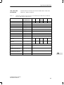
7-1
7-2
7-3
7-4
7-5
7-6
7-7
7-8
7-9
7-10
7-11
7-12
7-13
7-14
7-15
7-16
7-17
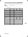
8-1
8-2
8-3
8-4
xii
ET 200B: Range of Applications . . . . . . . . . . . . . . . . . . . . . . . . . . . . . . . . . . .
Assignment of the Electronics Blocks to the Coding Slide Switch . . . . . . .
Approved Fuses for Terminal Blocks . . . . . . . . . . . . . . . . . . . . . . . . . . . . . . . .
Approved Conductor Cross-sections . . . . . . . . . . . . . . . . . . . . . . . . . . . . . . .
Pin Assignments of the Terminal Blocks . . . . . . . . . . . . . . . . . . . . . . . . . . . . .
Bus Connectors . . . . . . . . . . . . . . . . . . . . . . . . . . . . . . . . . . . . . . . . . . . . . . . . . .
Pin Assignment of the PROFIBUS-DP Interface . . . . . . . . . . . . . . . . . . . . . .
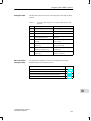
Type File Versions and Applications . . . . . . . . . . . . . . . . . . . . . . . . . . . . . . . .
LEDs on Digital ET 200B Modules and their Meanings . . . . . . . . . . . . . . . .
LEDs on Analog ET 200B Modules and their Meanings . . . . . . . . . . . . . . .
Function Blocks for Slave Diagnostics . . . . . . . . . . . . . . . . . . . . . . . . . . . . . .
Structure of Station Status 1 (Byte 0) . . . . . . . . . . . . . . . . . . . . . . . . . . . . . . .
Structure of Station Status 2 (Byte 1) . . . . . . . . . . . . . . . . . . . . . . . . . . . . . . .
Structure of the Master Station Number (Byte 3) . . . . . . . . . . . . . . . . . . . . .
Structure of the Manufacturer ID (Bytes 4, 5) . . . . . . . . . . . . . . . . . . . . . . . .
Bytes 13 to 16 for Diagnostics and Process Alarms . . . . . . . . . . . . . . . . . .
Possible Values for Byte 13 in Diagnostics Alarm . . . . . . . . . . . . . . . . . . . . .
Bytes 17 to 28 for Diagnostics Alarm . . . . . . . . . . . . . . . . . . . . . . . . . . . . . . .
Diagnostics Byte for an Analog Input/Analog Output Channel . . . . . . . . . .
ET 200B Digital Electronics Blocks . . . . . . . . . . . . . . . . . . . . . . . . . . . . . . . . .
ET 200B Digital Terminal Blocks . . . . . . . . . . . . . . . . . . . . . . . . . . . . . . . . . . .
Pin Assignment of Terminal Blocks TB1/DC; TB1-4/DC and TB3/DC
for ET 200B-16DI . . . . . . . . . . . . . . . . . . . . . . . . . . . . . . . . . . . . . . . . . . . . . . . .
Pin Assignment of Terminal
BlocksTB2/DC,TB2-4/DC,TB4/DCand TB4M/DCfor ET 200B-32DI
and ET 200B-32DI 0.2ms . . . . . . . . . . . . . . . . . . . . . . . . . . . . . . . . . . . . . . . . .
Pin Assignment of Terminal Blocks TB1/DC, TB1-4/DC and TB3/DC
for ET 200B-16DO . . . . . . . . . . . . . . . . . . . . . . . . . . . . . . . . . . . . . . . . . . . . . . .
Pin Assignment of Terminal Blocks TB2/DC; TB2-4/DC, TB4/DC
and TB4M/DC for ET 200B-16DO/2A . . . . . . . . . . . . . . . . . . . . . . . . . . . . . . .
Pin Assignment of Terminal Blocks TB2/DC, TB2-4/DC, TB4/DC
and TB4M/DC for ET 200B-32DO . . . . . . . . . . . . . . . . . . . . . . . . . . . . . . . . . .
Pin Assignment of Terminal Blocks TB1/DC; TB1-4/DC and TB3/DC
for ET 200B-8RO . . . . . . . . . . . . . . . . . . . . . . . . . . . . . . . . . . . . . . . . . . . . . . . .
Pin Assignment of Terminal Blocks TB1/DC; TB1-4/DC and TB3/DC
for ET 200B-8DI/8DO . . . . . . . . . . . . . . . . . . . . . . . . . . . . . . . . . . . . . . . . . . . . .
Pin Assignment of Terminal Blocks TB1/DC; TB1-4/DC and TB3/DC
for ET 200B-8DI/8DO HWA . . . . . . . . . . . . . . . . . . . . . . . . . . . . . . . . . . . . . . . .
Truth for Hardware Cutoff of ET 200B-8DI/8DO HWA . . . . . . . . . . . . . . . . .
Pin Assignment of Terminal Blocks TB2/DC, TB2-4/DC, TB4/DC
and TB4M/DC for ET 200B-16DI/16DO . . . . . . . . . . . . . . . . . . . . . . . . . . . . .
Pin Assignment of Terminal Blocks TB2/DC; TB2-4/DC and TB4/DC
for ET 200B-24DI/8DO and ET 200B-24DI/8DO 0.2ms . . . . . . . . . . . . . . . .
Pin Assignment of Terminal Block TB6/AC for ET 200B-16DI-AC . . . . . .
Pin Assignment of Terminal Block TB6/AC for ET 200B-16DO-AC . . . . .
Pin Assignment of Terminal Block TB6/AC for ET 200B-16RO-AC . . . . .
Pin Assignment of Terminal Block TB6/AC for ET 200B-8DI/8RO-AC . . .
Analog Electronics Blocks of ET 200B . . . . . . . . . . . . . . . . . . . . . . . . . . . . . .
Analog Terminal Block of ET 200B . . . . . . . . . . . . . . . . . . . . . . . . . . . . . . . . .
Compensating Box Type U with Current Stabilizer. . . . . . . . . . . . . . . . . . . .
Reference Junction with Built-in Power Supply Unit . . . . . . . . . . . . . . . . . . .
1-4
3-9
3-11
3-23
3-24
3-26
3-26
4-4
5-3
5-4
5-10
5-11
5-11
5-13
5-13
5-19
5-20
5-21
5-21
7-2
7-3
7-18
7-23
7-29
7-35
7-41
7-47
7-52
7-58
7-59
7-65
7-71
7-76
7-81
7-86
7-91
8-2
8-2
8-9
8-9
ET 200B Distributed I/O Station
EWA 4NEB 812 6089-02c
Contents
8-5
8-6
8-7
8-8
8-9
8-10
8-11
8-12
8-13
8-14
8-15
8-16
8-17
8-18
8-19
8-20
8-21
8-22
8-23
8-24
8-25
8-26
8-27
8-28
Possible Configurations for the Input Areas of ET 200B-4/8AI,
with only Voltage Sensors and Thermocouples Connected . . . . . . . . . . . .
Possible IDs for Configuring the Input Areas of ET 200B-4/8AI,
with only Thermal resistors and Resistors Connected . . . . . . . . . . . . . . . . .
Example for Configuring the Input Areas of ET 200B-4/8AI . . . . . . . . . . . .
Assignment of Terminals to Channel Groups . . . . . . . . . . . . . . . . . . . . . . . . .
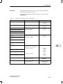
Parameters for ET 200B-4/8AI (6ES7 134-0KH01-0XB0) . . . . . . . . . . . . .
Representation of an Analog Input Value as a Bit Pattern
(6ES7 134-0KH01-0XB0) . . . . . . . . . . . . . . . . . . . . . . . . . . . . . . . . . . . . . . . . .
Description of the Bits (6ES7 134-0KH01-0XB0) . . . . . . . . . . . . . . . . . . . . .
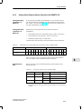
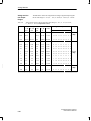
Representation of Digitized Measured Values of the ET 200B-4/8AI
(Measuring Ranges: 80 mV, 250 mV, 500 mV
and 1000 mV; Complement of Twos) . . . . . . . . . . . . . . . . . . . . . . . . . . . . .
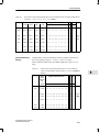
Representation of Digitized Measured Values of the ET 200B-4/8AI
(Measuring Ranges: 80 mV, 250 mV, 500 mV and
1000 mV; Amount and Sign) . . . . . . . . . . . . . . . . . . . . . . . . . . . . . . . . . . . .
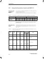
Representation of Digitized Measured Values of the ET 200B-4/8AI
for Resistance Measurement (Complement of Twos) . . . . . . . . . . . . . . . . .
Representation of Digitized Measured Values of the ET 200B-4/8AI
for Resistance Thermometers (Complement of Twos) . . . . . . . . . . . . . . . . .
Representation of Digitized Measured Values of the ET 200B-4/8AI
for Ni 100 Resistance Sensors (Complement of Twos) . . . . . . . . . . . . . . . .
Representation of Digitized Measured Values of the ET 200B-4/8AI
with Linearization; Type E Thermocouples (Nickel-Chrome/
Copper-Nickel, to IEC 548, Part 1; Complement of Twos) . . . . . . . . . . . . .
Representation of Digitized Measured Values of the ET 200B-4/8AI
with Linearization: Type J Thermocouple (Iron/Copper-Nickel
(Constantan), to IEC 584) (Complement of Twos) . . . . . . . . . . . . . . . . . . . .
Representation of Digitized Measured Values of the ET 200B-4/8AI
with Linearization: Type K Thermocouples (Nickel-Chrome/
Nickel-Aluminum, to IEC 584) (Complement of Twos) . . . . . . . . . . . . . . . . .
Representation of Digitized Measured Values of the ET 200B-4/8AI
with Linearization: Type L Thermocouples (Iron/Copper-Nickel
(Constantan), to DIN 43710) (Complement of Twos) . . . . . . . . . . . . . . . . . .
Representation of Digitized Measured Values of the ET 200B-4/8AI
with Linearization; Type N Thermocouples (Nickel-Chrome-Silicium/
Nickel-Silicium, to IEC 548-1; Complement of Twos) . . . . . . . . . . . . . . . . . .
Representation of Digitized Measured Values of the ET 200B-4/8AI
with Linearization; Type T Thermocouples
(Copper/Copper-Nickel, to IEC 548, Part 1; Complement of Twos) . . . . . .
Representation of Digitized Measured Values of the ET 200B-4/8AI
with Linearization; Type U Thermocouples (Copper/Copper-Nickel,
to DIN 43710; Complement of Twos) . . . . . . . . . . . . . . . . . . . . . . . . . . . . . . .
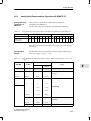
Representation of an Analog Input Value as a Bit Pattern for
SIMATIC S7 and ET 200B-4/8AI . . . . . . . . . . . . . . . . . . . . . . . . . . . . . . . . . . .
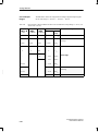
Possible Resolutions of Analog Values: ET 200B-4/8AI . . . . . . . . . . . . . . .
Representation of Digitized Measured Values of the ET 200B-4/8AI
(Measuring Ranges: 80 mV, 250 mV, 500 mV
and 1000 mV) . . . . . . . . . . . . . . . . . . . . . . . . . . . . . . . . . . . . . . . . . . . . . . . . .
Representation of Digitized Measured Values of the ET 200B-4/8AI
for Resistance Measurement . . . . . . . . . . . . . . . . . . . . . . . . . . . . . . . . . . . . . .
Representation of Digitized Measured Values of the ET 200B-4/8AI
ET 200B Distributed I/O Station
EWA 4NEB 812 6089-02c
8-20
8-21
8-22
8-23
8-24
8-26
8-26
8-27
8-28
8-29
8-30
8-31
8-32
8-33
8-34
8-35
8-36
8-37
8-38
8-39
8-39
8-40
8-41
xiii
Contents
8-29
8-30
8-31
8-32
8-33
8-34
8-35
8-36
8-37
8-38
8-39
8-40
8-41
8-42
8-43
8-44
8-45
8-46
8-47
8-49
8-50
8-51
8-52
8-53
8-54
8-55
8-56
8-57
8-58
xiv
for Pt 100 Resistance Sensors . . . . . . . . . . . . . . . . . . . . . . . . . . . . . . . . . . . . .
Representation of Digitized Measured Values of the ET 200B-4/8AI
for Ni 100 Resistance Sensors . . . . . . . . . . . . . . . . . . . . . . . . . . . . . . . . . . . . .
Representation of Digitized Measured Values of the ET 200B-4/8AI
with Linearization; Type E Thermocouples . . . . . . . . . . . . . . . . . . . . . . . . . . .
Representation of Digitized Measured Values of the ET 200B-4/8AI
with Linearization; Type J Thermocouples . . . . . . . . . . . . . . . . . . . . . . . . . . .
Representation of Digitized Measured Values of the ET 200B-4/8AI
with Linearization; Type K Thermocouples . . . . . . . . . . . . . . . . . . . . . . . . . . .
Representation of Digitized Measured Values of the ET 200B-4/8AI
with Linearization; Type L Thermocouples . . . . . . . . . . . . . . . . . . . . . . . . . . .
Representation of Digitized Measured Values of the ET 200B-4/8AI
with Linearization; Type N Thermocouples . . . . . . . . . . . . . . . . . . . . . . . . . .
Representation of Digitized Measured Values of the ET 200B-4/8AI
with Linearization; Type T Thermocouples . . . . . . . . . . . . . . . . . . . . . . . . . . .
Representation of Digitized Measured Values of the ET 200B-4/8AI
with Linearization; Type U Thermocouples . . . . . . . . . . . . . . . . . . . . . . . . . .
Terminal Assignment of the TB8 for ET 200B-4/8AI . . . . . . . . . . . . . . . . . . .
Possible Configurations for the Input Areas of ET 200B-4AI . . . . . . . . . . . .
Assignment of Terminals to Channels . . . . . . . . . . . . . . . . . . . . . . . . . . . . . . .
Parameters for ET 200B-4AI) . . . . . . . . . . . . . . . . . . . . . . . . . . . . . . . . . . . . .
Representation of an Analog Input Value as a Bit Pattern
(6ES7 134-0HF01-0XB0) . . . . . . . . . . . . . . . . . . . . . . . . . . . . . . . . . . . . . . . . .
Description of the Bits (6ES7 134-0HF01-0XB0) . . . . . . . . . . . . . . . . . . . . .
Representation of Digitized Measured Values of the ET 200B-4AI
(Measuring Ranges: 1.25 V, 2.5 V, 5 V, 10 V;
Complement of Twos) . . . . . . . . . . . . . . . . . . . . . . . . . . . . . . . . . . . . . . . . . . . .
Representation of Digitized Measured Values of the ET 200B-4AI
(Measuring Ranges: 1.25 V, 2.5 V, 5 V, 10 V;
Amount and Sign) . . . . . . . . . . . . . . . . . . . . . . . . . . . . . . . . . . . . . . . . . . . . . . . .
Representation of Digitized Measured Values of the ET 200B-4AI
(Measuring Ranges: 1.25 V, 2.5 V, 5 V, 10 V; Binary) . . . . . . .
Representation of Digitized Measured Values of the ET 200B-4AI
(Measuring Range: 20 mA; Complement of Twos) . . . . . . . . . . . . . . . . .
Representation of Digitized Measured Values of the ET 200B-4AI
(Measuring Range: 20 mA; Amount and Sign) . . . . . . . . . . . . . . . . . . . . .
Representation of Digitized Measured Values of the ET 200B-4AI
(Measuring Range: 0 ... 20 mA) . . . . . . . . . . . . . . . . . . . . . . . . . . . . . . . . . . . .
Representation of Digitized Measured Values of the ET 200B-4AI
(Measuring Range: 4 ... 20 mA) . . . . . . . . . . . . . . . . . . . . . . . . . . . . . . . . . . . .
Representation of an Analog Input Value as a Bit Pattern for
SIMATIC S7 and ET 200B-4AI . . . . . . . . . . . . . . . . . . . . . . . . . . . . . . . . . . . . .
Representation of Digitized Measured Values of the ET 200B-4AI
(Measuring Ranges: 1.25 V, 2.5 V, 5 V and 10 V) . . . . . . . . . .
Representation of Digitized Measured Values of the ET 200B-4AI
(Measuring Range: 20 mA) . . . . . . . . . . . . . . . . . . . . . . . . . . . . . . . . . . . . .
Representation of Digitized Measured Values of the ET 200B-4AI
(Measuring Ranges: 0 to 20 mA and 4 to 20 mA) . . . . . . . . . . . . . . . . . . . . .
Terminal Assignment of the TB8 for ET 200B-4AI . . . . . . . . . . . . . . . . . . . . .
Possible Configurations for the Output Areas of ET 200B-4AO . . . . . . . . .
Assignment of Terminals to Channels . . . . . . . . . . . . . . . . . . . . . . . . . . . . . . .
Parameters for ET 200B-4AO . . . . . . . . . . . . . . . . . . . . . . . . . . . . . . . . . . . . . .
8-42
8-42
8-43
8-43
8-44
8-44
8-45
8-45
8-46
8-48
8-61
8-62
8-63
8-65
8-65
8-66
8-66
8-67
8-67
8-68
8-69
8-69
8-70
8-70
8-71
8-71
8-73
8-82
8-83
8-84
ET 200B Distributed I/O Station
EWA 4NEB 812 6089-02c
Contents
8-59
8-60
8-61
8-62
8-63
8-64
8-65
A-1
A-2
A-3
A-4
A-5
A-6
A-7
B-1
B-2
B-3
B-4
C-1
C-2
C-3
C-4
C-5
D-1
D-2
D-3
D-4
D-5
D-6
D-7
D-8
E-1
E-2
E-3
E-4
E-5
E-6
Representation of an Analog Output Value as a Bit Pattern
(6ES7 135-0HF01-0XB0) . . . . . . . . . . . . . . . . . . . . . . . . . . . . . . . . . . . . . . . . .
Description of the Bits (6ES7 135-0HF01-0XB0) . . . . . . . . . . . . . . . . . . . . .
Analog Output Signals of the ET 200B-4AO (Value Ranges:
10 V, 0 ... 10 V, 20 mA, 0 ... 20 mA, 4 ... 20 mA;
Complement of Twos) . . . . . . . . . . . . . . . . . . . . . . . . . . . . . . . . . . . . . . . . . . . .
Representation of an Analog Output Value as a Bit Pattern for
SIMATIC S7 and ET 200B-4AO . . . . . . . . . . . . . . . . . . . . . . . . . . . . . . . . . . . .
Representation of Digitized Measured Values of the ET 200B-4AO
(Output Ranges: 0 to 10 V and 10 V) . . . . . . . . . . . . . . . . . . . . . . . . . . . . .
Representation of Digitized Measured Values of the ET 200B-4AO
(Output Ranges: 20 mA, 0 to 20 mA and 4 to 20 mA) . . . . . . . . . . . . . . .
Terminal Assignment of the TB8 for ET 200B-4AO . . . . . . . . . . . . . . . . . . . .
Designations of Type Files for Digital Modules . . . . . . . . . . . . . . . . . . . . . . .
Designations of Type Files for Analog Modules . . . . . . . . . . . . . . . . . . . . . .
Characteristics according to EN 50170, Part 3 for
ET 200B-16DI, ET 200B-32DI, ET 200B-32DI 0.2ms,
ET 200B-16DO, ET 200B-16DO/2A . . . . . . . . . . . . . . . . . . . . . . . . . . . . . . . .
Characteristics according to EN 50170, Part 3 for ET 200B-32DO,
ET 200B-8RO, ET 200B-8DI/8DO, ET 200B-8DI/8DO HWA . . . . . . . . . . .
Characteristics according to EN 50170, Part 3 for ET 200B-16DI/16DO,
ET 200B-24DI/8DO, ET 200B-24DI/8DO 0.2ms . . . . . . . . . . . . . . . . . . . . . .
Characteristics according to EN 50170, Part 3 for ET 200B-16DI-AC,
ET 200B-16DO-AC, ET 200B-16RO-AC, ET 200B-8DI/8RO-AC . . . . . . . .
Characteristics according to EN 50170, Part 3 for ET 200B-4/8AI,
ET 200B-4AI, ET 200B-4AO . . . . . . . . . . . . . . . . . . . . . . . . . . . . . . . . . . . . . . .
Structure of the Configuration Telegram for Digital ET 200B Modules . . .
IDs for Digital ET 200B Modules . . . . . . . . . . . . . . . . . . . . . . . . . . . . . . . . . . .
Structure of the Configuration Telegram for Analog ET 200B Modules . . .
IDs for Analog ET 200B Modules . . . . . . . . . . . . . . . . . . . . . . . . . . . . . . . . . .
Assignment of Terminals to Channel (Groups) . . . . . . . . . . . . . . . . . . . . . . .
Codings for the Integration Times of the 4/8AI . . . . . . . . . . . . . . . . . . . . . . .
Codings for the Measuring Ranges of the Analog Input Modules . . . . . . .
Assignment of Terminals to Channels . . . . . . . . . . . . . . . . . . . . . . . . . . . . . . .
Codings for Output Ranges of the Analog Output Module . . . . . . . . . . . . .
LEDs on Analog ET 200B Modules and their Meanings . . . . . . . . . . . . . . .
Structure of Slave Diagnostics for Digital ET 200B,
Operation with IM 308-B . . . . . . . . . . . . . . . . . . . . . . . . . . . . . . . . . . . . . . . . . .
Structure of Slave Diagnostics for Analog ET 200B,
Operation with IM 308-B . . . . . . . . . . . . . . . . . . . . . . . . . . . . . . . . . . . . . . . . . .
Diagnostics Data, Bytes 9 to 12 . . . . . . . . . . . . . . . . . . . . . . . . . . . . . . . . . . . .
Possible Values for Byte 9 . . . . . . . . . . . . . . . . . . . . . . . . . . . . . . . . . . . . . . . . .
Diagnostics Data, Bytes 13 to 15 . . . . . . . . . . . . . . . . . . . . . . . . . . . . . . . . . . .
IDs for ET 200B . . . . . . . . . . . . . . . . . . . . . . . . . . . . . . . . . . . . . . . . . . . . . . . . . .
Content and Meanings of the Bytes in the
Parameterization Telegram . . . . . . . . . . . . . . . . . . . . . . . . . . . . . . . . . . . . . . .
LEDs on Analog ET 200B Modules and their Meanings . . . . . . . . . . . . . . .
Diagnostics Data, Bytes 9 to 12 . . . . . . . . . . . . . . . . . . . . . . . . . . . . . . . . . . . .
Possible Values for Byte 9 . . . . . . . . . . . . . . . . . . . . . . . . . . . . . . . . . . . . . . . . .
Bytes 13 to 16 for Diagnostics Alarm . . . . . . . . . . . . . . . . . . . . . . . . . . . . . . .
Diagnostics Byte for an Analog Input/Analog Output Channel . . . . . . . . . .
Possible IDs for Configuring Input and Output and Areas . . . . . . . . . . . . . .
ET 200B Distributed I/O Station
EWA 4NEB 812 6089-02c
8-85
8-85
8-86
8-87
8-87
8-88
8-90
A-2
A-3
A-5
A-6
A-7
A-8
A-9
B-2
B-2
B-3
B-3
C-5
C-8
C-8
C-10
C-13
D-2
D-6
D-7
D-9
D-10
D-10
D-11
D-13
E-2
E-4
E-5
E-5
E-6
E-7
xv
Contents
E-7
E-8
E-9
F-1
F-2
F-3
F-4
F-5
F-6
xvi
Parameters for ET 200B-4/8AI (6ES7 134-0KH01-0XB0) . . . . . . . . . . . . .
Parameters for ET 200B-4AI (6ES7 134-0HF01-0XB0) . . . . . . . . . . . . . . .
Parameters for ET 200B-4AO (6ES7 135-0HF01-0XB0) . . . . . . . . . . . . . . .
Order Numbers, Electronics Blocks for ET 200B . . . . . . . . . . . . . . . . . . . . .
Order Numbers, Terminal Blocks for ET 200B . . . . . . . . . . . . . . . . . . . . . . . .
Order Numbers, Labeling Strips . . . . . . . . . . . . . . . . . . . . . . . . . . . . . . . . . . . .
Accessories for the ET 200 Distributed I/O System . . . . . . . . . . . . . . . . . . .
Manuals for ET 200 in SIMATIC S5 . . . . . . . . . . . . . . . . . . . . . . . . . . . . . . . . .
Manuals for STEP 7 and SIMATIC S7 . . . . . . . . . . . . . . . . . . . . . . . . . . . . . .
E-8
E-9
E-10
F-2
F-3
F-3
F-4
F-5
F-5
ET 200B Distributed I/O Station
EWA 4NEB 812 6089-02c
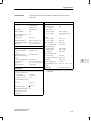
1
System Overview
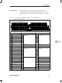
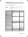
In this Chapter
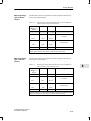
The System Overview gives you information on the following:
In Section
ET 200B Distributed I/O Station
EWA 4NEB 812 6089-02c
you will find
on Page
1.1
What is the ET 200 distributed I/O system?
1-2
1.2
What is ET 200B?
1-3
1-1
System Overview
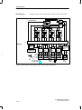
1.1
1
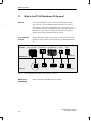
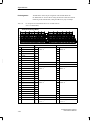
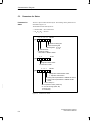
What is the ET 200 Distributed I/O System?
Definition
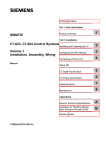
The ET 200 distributed I/O system is based on the PROFIBUS standard
(EN 50170, Part 1) and the PROFIBUS-DP standard (EN 50170, Part 3).
The field bus on which the ET 200 distributed I/O system is based is a version of PROFIBUS known as PROFIBUS-DP (DP = Dezentrale Peripherie, or
distributed I/O). This version is designed for minimum reaction times in
communication with the distributed inputs and outputs.
The Components
of ET 200
DP master
The distributed input/output system consists of active stations (DP masters)
and passive stations (DP slaves) interconnected by the PROFIBUS-DP field
bus.
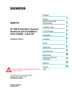
S5-115/135/155U S7-300/M7-300 S7-400/M7-400
S5-95U
STEP 7
COM ET 200
PROFIBUS-DP
DP slaves
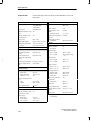
Figure 1-1
ET 200B
ET 200C
ET 200M
S5-95U
Field devices
Typical PROFIBUS-DP Configuration with SIMATIC S5/S7/M7
SINEC L2-DP =
PROFIBUS-DP
1-2
PG/PC
SINEC L2-DP is the PROFIBUS-DP from Siemens.
ET 200B Distributed I/O Station
EWA 4NEB 812 6089-02c
System Overview
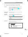
1.2
What is the ET 200B?
Definition
The ET 200B (B stands for ”block I/O”) belongs to the ET 200 distributed
I/O system with the PROFIBUS-DP field bus. ET 200B is a DP slave having
IP 20 protection.
The ET 200B distributed I/O station incorporates an integral port for connection to the PROFIBUS-DP bus and digital or analog inputs/outputs.
Range of Modules
The range of modules for the ET 200B includes:
24 V DC digital modules
120/230 V AC digital modules
Analog modules
Application
Thanks to its compact and flat design, the ET 200B distributed I/O station is
primarily suited to applications where space is a priority.
The ET 200B distributed I/O station can be mounted either on a standard sectional rail or directly onto the wall. Vertical and horizontal installation are
both possible.
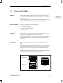
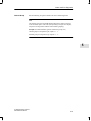
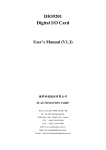
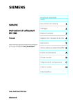
Components
The ET 200B consists of 2 parts: the terminal block and the electronics
block.
The terminal block (TB) incorporates the permanent wiring and does not contain any function-related electrical components. The electronics block is attached to the terminal block. The electronics block (EB) contains the logic
circuits.
The terminal block and the electronics block have matching mechanical coding elements to prevent destruction of the electronics block.
Electronics block
=
+
Terminal block
Figure 1-2
ET 200B Distributed I/O Station
EWA 4NEB 812 6089-02c
ET 200B
Components of ET 200B
1-3
1
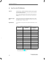
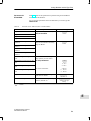
System Overview
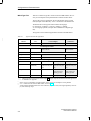
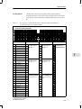
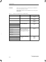
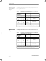
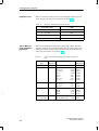
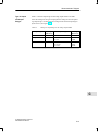
Compatible with
All ET 200B modules can be addressed with the PROFIBUS-DP bus protocol.
ET 200B can be operated with the following systems:
1
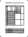
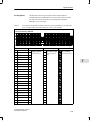
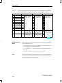
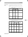
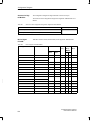
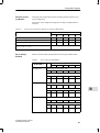
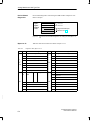
Table 1-1
ET 200B: Range of Applications
Operating with
In system
SIMATIC S5
Configurable with
IM 308-B master interface (release COM ET 200 V4.x
5 and higher)
version 4.0 and higher:
digital modules
version 4.1 and higher:
analog modules
IM 308-C master interface (release COM ET 200 Windows
1 and higher)
(version 1.0 and higher)
SIMATIC S7/M7
S7/M7 DP master with integral
PROFIBUS-DP interface
STEP 7
version 2.0 and higher:
digital modules
version 3.0 and higher:
analog modules
S7 Slave
Theanalog modules of ET 200B can be operated as S7 slaves in conjunction
with SIMATIC S7/ M7 and STEP 7 (V3.0 and higher). This means that all the
functions of the central S7 I/O modules are also at your disposal for the
ET 200B analog modules.
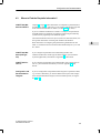
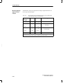
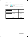
The Next Sections
The next sections of this chapter contain an overview of the components of
ET 200B.
In Section
1-4
you will find
on Page
1.2.1
Terminal Block
1-5
1.2.2
Electronics Block
1-6
ET 200B Distributed I/O Station
EWA 4NEB 812 6089-02c
System Overview
1.2.1
Terminal Block
Definition
The terminal block incorporates the permanent wiring.
Characteristics
The terminal block has the following characteristics:
1
The supply voltage for the electronics block (logic) can be switched on/
off (except for the TB6/AC terminal block).
The terminal block can be mounted both on standard sectional rails and
on smooth surfaces, so direct wall mounting is possible.
The PROFIBUS-DP bus is interfaced via a SINEC L2 bus connector.
Station numbers between 00 and 99 can be set with the aid of a tool such
as a screwdriver:
– When operating with an IM 308-B master interface, station numbers
3 to 99 are permissible.
– When operating with an IM 308-C master interface or with an S7/M7
DP master, station numbers 1 to 99 are permissible.
ET 200B Distributed I/O Station
EWA 4NEB 812 6089-02c
1-5
System Overview
1.2.2
1
Electronics Block
Definition
The electronics block contains the logic circuits and is plugged onto the terminal block.
Characteristics
The electronics block has the following characteristics:
There is galvanic isolation between the PROFIBUS-DP bus and the internal electronics.
The block has LEDs for indicating the following:
– Voltage supply to the logic circuits (RUN)
– Bus fault (BF)
– Group diagnostics: short-circuit, wire break or load voltage failure
(DIA, only for electronics blocks which can be diagnosed)
– Load voltage monitoring (L1+, L2+, L3+, L4+, only for digital electronics blocks (24 V DC) with output channels)
– Status of the inputs or outputs (for digital electronics blocks only)
Labeling strips are inserted in the electronics block. Fill in the labeling
strips to ensure unambiguous assignment of name, channel and LED.
1-6
ET 200B Distributed I/O Station
EWA 4NEB 812 6089-02c
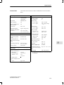
2
Technical Description
In this Chapter
This chapter contains information on:
In Section
ET 200B Distributed I/O Station
EWA 4NEB 812 6089-02c
you will find
on Page
2.1
Design of the Terminal Block
2-2
2.2
Design of the Electronics Block
2-4
2-1
Technical Description
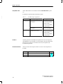
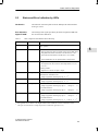
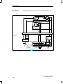
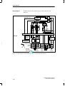
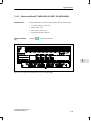
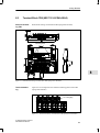
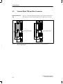
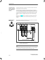
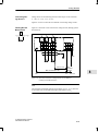
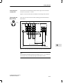
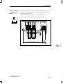
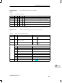
2.1
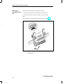
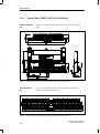
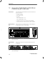
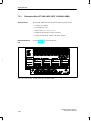
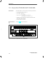
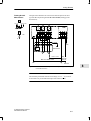
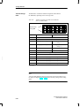
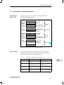
Design of the Terminal Block
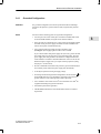
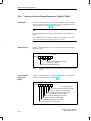
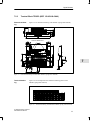
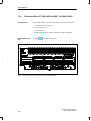
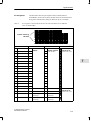
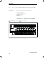
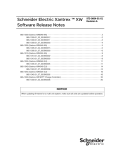
Design Principle of
the Digital TBs
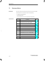
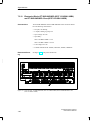
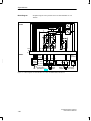
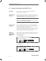
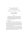
All digital terminal blocks are built on the same design principle explained
below using the TB1/DC terminal block as a typical example:
2
1
2
10
3
9
8
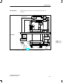
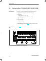
Figure 2-1
7
6
5
4
The TB1/DC
1 Coding slide switch
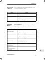
2 Fuse
3 STOP/RUN switch (not TB6/AC). The power supply for logic circuits
in the electronics block can be switched on or off with the STOP/RUN
switch. It can also be used to switch the ET 200B distributed I/O station
on and off.
4 Terminals for power supplies
5 Terminals for inputs/outputs
6 Slide for removing the terminal block from the standard sectional rail
7 M4 screw (connects chassis to PE)
8 M5 screw for connecting PE
9 PROFIBUS-DP interface
10 Switch for setting the station number (the station number is valid only
after operation of the STOP/RUN switch (STOP –> RUN)).
2-2
ET 200B Distributed I/O Station
EWA 4NEB 812 6089-02c
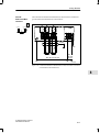
Technical Description
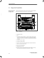
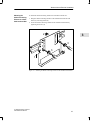
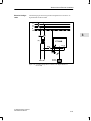
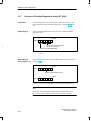
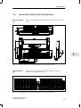
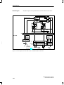
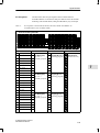
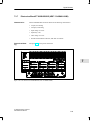
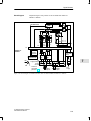
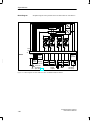
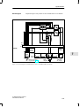
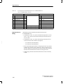
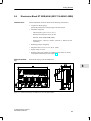
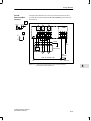
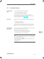
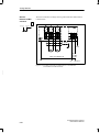
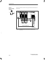
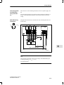
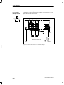
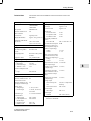
Design Principle of
the TB8 Analog
Block
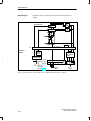
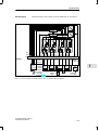
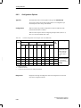
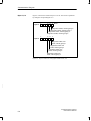
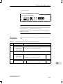
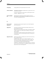
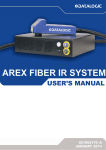
On the front of the TB8 analog terminal block, there are an additional 5 coding switches:
1
2
2
10
3
9
8
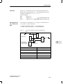
Figure 2-2
7
6
5
4
The TB8
1 Coding slide switch
2 Fuse
3 STOP/RUN switch. The power supply for logic circuits in the electronics block can be switched on or off with the STOP/RUN switch. It can
also be used to switch the ET 200B distributed I/O station on and off.
4 Terminals for power supplies
5 Terminals for inputs/outputs
6 Slide for removing the terminal block from the standard sectional rail
7 Coding connectors. You use the coding connectors to set the wiring of
the TB8 for analog value processing.
8 M5 screw for connecting PE
9 PROFIBUS-DP interface
10 Switch for setting the station number (the station number is valid only
after operation of the STOP/RUN switch (STOP –> RUN)).
ET 200B Distributed I/O Station
EWA 4NEB 812 6089-02c
2-3
Technical Description
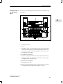
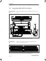
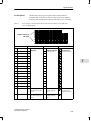
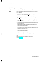
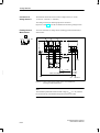
2.2
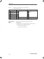
Design of the Electronics Block
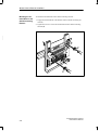
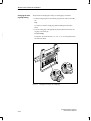
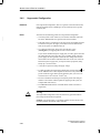
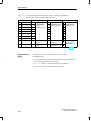
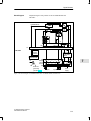
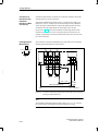
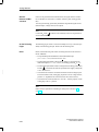
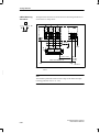
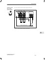
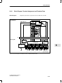
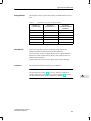
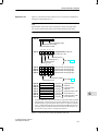
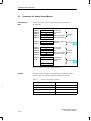
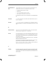
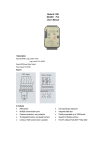
Design Principle
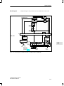
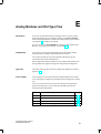
All types of electronics block are built on the same design principle which is
explained below using the ET 200B-16DI electronics block as a typical example:
2
6
1
5
4
Figure 2-3
3
2
ET 200B-16DI Electronics Block
1 Ventilation slots
2 Screws for mounting the electronics block on the terminal block
3 Printed schematic diagram
4 Indication of the coding slide switch setting on the top of the terminal
block
5 Labeling strip; for indicating the status of the inputs or outputs in the
case of digital electronics blocks with LEDs
6 LEDs for
Voltage supply to the logic circuits (RUN)
Bus fault (BF)
Group diagnostics; short-circuit, wire break or load voltage failure
(DIA, only for electronics blocks which can be diagnosed)
Load voltage monitor (L1+, L2+, L3+, L4+, depending on the electronics block: see Section 5.2)
Coding
The electronics blocks are coded by the manufacturer.
Some types of electronics blocks have a recess at the bottom. This recess
ensures that the terminal block is assigned safely to the correct electronics
block.
2-4
ET 200B Distributed I/O Station
EWA 4NEB 812 6089-02c
Mechanical and Electrical Installation
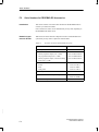
In the Chapter
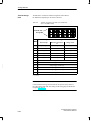
This chapter contains information on:
In Section
Technical Data
3
you will find
on Page
3.1
Installing and Setting the Terminal Block
3-2
3.2
Installing the Electronics Block
3-12
3.3
Dismantling the Terminal Block and Electronics Block
3-14
3.4
Electrical Installation
3-16
3.5
Wiring the Terminal Block
3-22
3.6
Wiring the Bus Interface
3-26
You will find a detailed description of the technical data of the ET 200B
modules in Sections 6, 7 and 8.
ET 200B Distributed I/O Station
EWA 4NEB 812 6089-02c
3-1
Mechanical and Electrical Installation
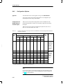
3.1
Installing and Setting the Terminal Block
Two Methods
You can install the terminal block either
on a standard sectional rail (35
15 mm or 35
7.5 mm to
DIN EN 50022)
or
on smooth surfaces, i.e. direct wall mounting (for dimensions of the
3
mounting holes see Dimensional Drawings in Sections 7 and 8).
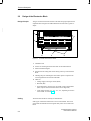
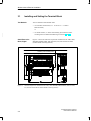
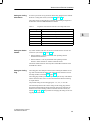
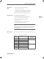
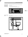
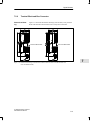
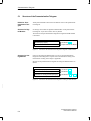
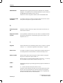
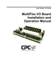
Small Electronics
Block, Digital
Figure 3-1 shows the clearances required for installation of the 16DI, 16DO,
8DI/8DO, 8DI/8DO HWA, 8RO and 4/8AI, 4AI, 4AO electronics blocks
(without shield connecting element):
Handling and heat dissipation
For swiveling/disengaging the electronics block
Figure 3-1
3-2
Clearances Required for Installation of the 16DI, 16DO, 8DI/8DO, 8DI/8DO HWA, 8RO and 4/8AI,
4AI, 4AO Electronics Blocks (without Shield Connecting Element)
ET 200B Distributed I/O Station
EWA 4NEB 812 6089-02c
Mechanical and Electrical Installation
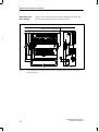
Large Electronics
Block
Figure 3-2 shows the clearances required for installation of the 16DI-AC,
16DO-AC, 32DI, 16DO/2A, 32DO, 16DI/16DO, 24DI/8DO, 16RO-AC and
8DI/8RO-AC electronics blocks:
Handling and heat dissipation
For swiveling/disengaging the electronics block
3
Figure 3-2
Clearances Required for Installation of the 16DI-AC, 16DO-AC, 32DI, 16DO/2A, 32DO, 16DI/16DO,
24DI/8DO, 16RO-AC and 8DI/8RO-AC Electronics Blocks
ET 200B Distributed I/O Station
EWA 4NEB 812 6089-02c
3-3
Mechanical and Electrical Installation
Small Electronics
Block, Analog
Figure 3-3 shows the clearances required for installation of the 4/8AI, 4AI,
4AO electronics blocks (with shield connecting element):
Handling and heat dissipation
For swiveling/disengaging the electronics block
3
Figure 3-3
3-4
Clearances Required for Installation of the 4/8AI, 4AI and 4AO Electronics Blocks (with Shield
Connecting Element)
ET 200B Distributed I/O Station
EWA 4NEB 812 6089-02c
Mechanical and Electrical Installation
Shield Connecting
Element for TB8
In the case of analog value processing, we recommend that the cable shielding of the signal lines be connected directly at terminal block TB8.
For this application, you can hang the TB8 onto a shield connecting element
after first mounting the shield connecting element on a standard sectional rail
(35 15 or 35 7.5 mm to DIN EN 50022) or a smooth surface.
To secure the shield braiding, install metal terminal elements on the shield
connecting element.
You can order the shield connecting element and the terminal elements under
the following numbers:
3
Shield connecting element → Order No. 6ES7 193-0CD40-7XA0
Terminal elements (set of two):
– Single version → Order No. 6ES7 390-5BA00-0AA0
(one shield cable per terminal element with a diameter of 3 to 8 mm to
be clamped)
– Double version → Order No. 6ES7 390-5AB00-0AA0
(two shield cables per terminal element with a diameter of 2 to 6 mm
to be clamped)
Note
If you mount the TB8 with shield connecting element on a standard sectional
rail, you must install the ET 200B horizontally.
ET 200B Distributed I/O Station
EWA 4NEB 812 6089-02c
3-5
Mechanical and Electrical Installation
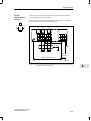
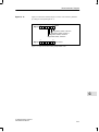
Mounting on a
Standard Sectional
Rail
To mount the terminal block on a standard sectional rail...
1. Hang the terminal block on the standard sectional rail (1) and
2. Swing it back until the slide on the module snaps into place (2).
Note:
The meanings of the coding switch settings are explained in Table 3-1.
3
Figure 3-4
3-6
Hanging the Terminal Block on the Standard Sectional Rail and Setting the
Coding Slide Switch
ET 200B Distributed I/O Station
EWA 4NEB 812 6089-02c
Mechanical and Electrical Installation
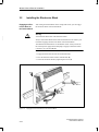
Mounting the
Shield Connecting
Element on a Standard Sectional Rail
To mount the shield connecting element on a standard sectional rail...
1. Hang the shield connecting element on the standard sectional rail from
below (1) and swing it back (2).
2. Secure the shield connecting element on the standard sectional rail by
tightening the screws (3).
3
2
3
3
1
Figure 3-5
ET 200B Distributed I/O Station
EWA 4NEB 812 6089-02c
Mounting the Shield Connecting Element on the Standard Sectional Rail
3-7
Mechanical and Electrical Installation
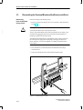
Mounting the Terminal Block on the
Shield Connecting
Element
To mount the terminal block on the shield connecting element ...
1. Engage the terminal block in the brackets of the terminal connecting element (1).
2. Tighten the screws to secure the terminal block to the shield connecting
element (2).
3
1
2
2
2
Figure 3-6
3-8
Mounting the Terminal Block on the Shield Connecting Element
ET 200B Distributed I/O Station
EWA 4NEB 812 6089-02c
Mechanical and Electrical Installation
Setting the Coding
Slide Switch
In order to prevent the wrong electronics block being plugged in, the terminal
block has a coding slide switch (see Section 2.1, Figure 2-1, 1).
The coding switch can be engaged in 6 settings. Each setting is assigned to a
module class of the ET 200B distributed I/O station:
Table 3-1
Setting the Station
Number
Assignment of the Electronics Blocks to the Coding Slide Switch
Setting
Module Class
1
24 V digital modules
2
24 V special modules
3
Analog modules
4
Reserved
5
Reserved
6
230 V digital modules
3
Any station number from 00 to 99 can be set with the aid of a tool such as a
screwdriver (see Section 2.1, Figure 2-1, 10):
Station numbers 3 to 99 are permissible when operating with the
IM308-B master interface.
Station numbers 1 to 99 are permissible when operating with the
IM 308-C master interface or with the S7/M7 DP master.
The station number becomes valid only after a STOP/RUN transition of the
ET 200B slave station.
Setting the Coding
Plug
The coding plus of the TB8 provide the means of setting the defaults for analog value measurement and analog value output for each channel in the case
of analog modules (see Section 2-1, Figure 2-2, 7).
The coding plugs enable you to set the input or output circuitry of the TB8 to
suit the measured value sensor or load connected and the desired measuring
or output method.
The possible settings for the coding plugs are: ”A”, ”B”, ”C” and ”D”.
The relationships between the various settings of the coding plugs and the
measurement/output method and the measured value sensors and loads are
detailed in the sections dealing with the individual electronics blocks (see
Sections 8.4 through 8.6). The procedure for changing the settings of the coding plugs is described below.
ET 200B Distributed I/O Station
EWA 4NEB 812 6089-02c
3-9
Mechanical and Electrical Installation
Changing the Coding Plug Setting
The procedure for changing the setting of a coding plug is as follows:
1. Pull the coding plug above the channel group from its socket in the TB8
(1).
Tip:
It is easiest to reset the coding plugs before installing the electronics
block.
2. Turn the coding plug to the appropriate position (2) and reinsert the coding plug in its socket (3).
3
Correct setting:
The pointer ”∆” beside the letter ”A”, ”B”, ”C” or ”D” must point toward
the electronics block.
3
1
Figure 3-7
3-10
2
Changing the Setting of the Coding Plug
ET 200B Distributed I/O Station
EWA 4NEB 812 6089-02c
Mechanical and Electrical Installation
Terminal Block
Fuses
The fuse (F1) in the terminal block protects against:
short-circuit in the sensor supply
reversed polarity of the voltage supply to the internal logic
voltage spikes in the voltage supply to the internal logic
If the fuse trips the module’s internal logic is deenergized.
Changing the Fuse
Proceed as follows when changing the fuse:
3
1. Switch the STOP/RUN switch to the “STOP” position.
2. Pull the electronics block off the terminal block.
3. Pry the fuse out of its base using a screwdriver.
4. Insert the new fuse.
5. Reinstall the electronics block on the terminal block.
6. Switch the RUN/STOP switch to “RUN”.
Note
The TB6/AC terminal block has no STOP/RUN switch. Make sure that the
external power supply is switched off before removing the electronics block
and changing the fuse.
Approved Fuses
Install only the fuses listed in Table 3-2. The fuses can be ordered in packs of
ten.
Table 3-2
Terminal
Block
ET 200B Distributed I/O Station
EWA 4NEB 812 6089-02c
Approved Fuses for Terminal Blocks
Fuse
Order No.
(pack of 10)
TB6/AC
Miniature fuse TR5-T 1.0; 250 V AC
6ES7 193-0DC00-0XA0
TB1/DC
Miniature fuse TR5-T 1.6; 250 V
6ES7 193-0DA00-0XA0
TB1-4/DC
Miniature fuse TR5-T 1.6; 250 V
TB3/DC
Miniature fuse TR5-T 1.6; 250 V
TB8-analog
Miniature fuse TR5-T 1.6; 250 V
TB2/DC
Miniature fuse TR5-T 2.5; 250 V
TB2-4/DC
Miniature fuse TR5-T 2.5; 250 V
TB4/DC
Miniature fuse TR5-T 2.5; 250 V
TB4M/DC
Miniature fuse TR5-T 2.5; 250 V
6ES7 193-0DB00-0XA0
3-11
Mechanical and Electrical Installation
3.2
Installing the Electronics Block
Engaging the Electronics Block on
the Terminal Block
!
3
After coding the terminal block via the coding slide switch, you can engage
the electronics block on the terminal block:
Warning
Avoid electrical destruction of the electronics block.
Always set the STOP/RUN switch of the terminal block to the “STOP” position before engaging the electronics block on the terminal block!
The TB6/DC terminal block has no STOP/RUN switch. Always switch off
the external power supply before attempting to engage an electronics block
(120/230 V AC) onto the TB6/DC.
1. Engage the electronics block on the terminal block (1).
2. Press the electronics block onto the terminal block (2).
3. Secure the electronics block by tightening the screws (3).
Figure 3-8
3-12
Engaging the Electronics Block on the Terminal Block
ET 200B Distributed I/O Station
EWA 4NEB 812 6089-02c
Mechanical and Electrical Installation
Labeling the Electronics Block
A labeling strip is inserted in the electronics block.
Individual DIN A4 sheets consisting of several labeling strips can be ordered
separately. Please refer to Appendix F for order numbers.
Versions
For electronics blocks with 16DI, 16DO, 8DI/8DO, 8DI/8DO HWA, 8RO,
4/8AI, 4AI, 4AO:
10 labeling strips on one DIN A4 sheet
For electronics blocks with 16DI-AC, 16DO-AC, 32DI, 16DO/2A, 32DO,
16DI/16DO, 24DI/8DO, 16RO-AC, 8DI/8RO-AC:
7 large labeling strips and 9 small labeling strips on one DIN A4 sheet.
ET 200B Distributed I/O Station
EWA 4NEB 812 6089-02c
3-13
3
Mechanical and Electrical Installation
3.3
DismantlingtheTerminalBlockandtheElectronicsBlock
Dismantling
(from the Standard
Sectional Rail)
!
3
Proceed according to the following steps:
1. Remove the electronics block in the reverse sequence to that described in
Figure 3-8.
Warning
Avoid electrical destruction of the electronics block.
Always set the STOP/RUN switch of the terminal block to the “STOP” position before disengaging the electronics block from the terminal block or
installing a replacement electronics block!
The TB6/DC terminal block has no STOP/RUN switch. Always switch off
the external power supply before attempting to disengage an electronics
block (120/230 V AC) from the TB6/DC or installing a replacement electronics block.
2. Press the slide (1) on the bottom of the terminal block down using a
screwdriver and
3. Swing the terminal block out of the standard sectional rail (2).
1
2
Figure 3-9
3-14
Dismantling the ET 200B
ET 200B Distributed I/O Station
EWA 4NEB 812 6089-02c
Mechanical and Electrical Installation
Dismantling
(from the Shield
Connecting Element)
!
Proceed according to the following steps:
1. Remove the electronics block in the reverse sequence to that described in
Figure 3-8.
Warning
Avoid electrical destruction of the electronics block.
Always set the STOP/RUN switch of the terminal block to the “STOP” position before disengaging the electronics block from the terminal block or
installing a replacement electronics block!
The TB6/DC terminal block has no STOP/RUN switch. Always switch off
the external power supply before attempting to disengage an electronics
block (120/230 V AC) from the TB6/DC or installing a replacement electronics block.
2. Remove the terminal block and the shield connecting element in the reverse sequence to that described in Figures 3-5 and 3-6.
ET 200B Distributed I/O Station
EWA 4NEB 812 6089-02c
3-15
3
Mechanical and Electrical Installation
3.4
Electrical Installation
Introduction
The ET 200B distributed I/O station allows both grounded and ungrounded
configurations.
Next Sections
The following two sections explain the configuration rules and give circuit
examples for
3
In Section
you will find
on Page
3.4.1
Grounded Configuration
3-17
3.4.2
Ungrounded Configuration
3-20
The numbers in the text cross-reference the components shown in the figures.
3-16
ET 200B Distributed I/O Station
EWA 4NEB 812 6089-02c
Mechanical and Electrical Installation
3.4.1
Grounded Configuration
Definition
In a grounded configuration, the reference potential of the ET 200B logic
circuits and the protective ground conductor (PE) are galvanically interconnected.
Rules
You must note the following points for a grounded configuration:
You must provide a main switch (1) in accordance with DIN VDE 0100
3
for the ET 200B modules, the signal sensors and the actuators.
If the spur lines are a maximum of 3 m long and are ground-fault-resistant
and short-circuit-proof, the supply connection for the ET 200B and the
load circuit requires no additional fuse (2).
Use a Siemens load power supply unit (3) in the 6EV1 series
(Catalog ET 1) for supplying the 24 V DC to the ET 200B.
If you connect another load power supply unit (24 V DC), please note that
the voltage must be in the range 20 to 30 V (including ripple). The load
power supply unit must generate a functional low voltage with safe electrical isolation in accordance with DIN VDE 0106. In the case of non-stabilized load power supply units, you require a back-up capacitor (rating
200 F per 1 A load current).
Provide a detachable connection to the protective ground conductor (4) in
the secondary circuit of the load power supply unit (M terminal).
A fuse (5) is required for fusing the supply voltage.
For both grounded and ungrounded configurations, the PE terminal
of
the ET 200B must have a low-impedance connection to the protective
ground conductor or the cabinet ground (machine parts) (6).
Use a minimum cross-section of 4 mm2 and a maximum of 10 mm2 for
equipotential bonding and ground connections.
All machine parts must be grounded.
The PROFIBUS-DP interface of terminal blocks release 2 and later is
ungrounded.
ET 200B Distributed I/O Station
EWA 4NEB 812 6089-02c
3-17
Mechanical and Electrical Installation
Connecting the
Reference Potential of the Logic
Circuits to PE
For a grounded configuration, you must also do the following at the digital
terminal blocks:
1. Connect the PE terminal to the lower screw.
2. Tighten the upper screw. The upper screw connects the ground potential
to PE.
3
PE
Figure 3-10 Both Screws Tightened in a Grounded Configuration
Electrical Configuration
The following figure shows the grounded configuration for 24 V DC digital
modules of the ET 200B:
L1
L2
L3
N
PE
(1)
(2)
ET 200B
(3)
M
L+ M
L+ (5)
(4)
(6)
I/O
M
L+
Sensor/
actuator
Figure 3-11 Grounded Configuration for 24 V DC Digital Modules of the ET 200B
3-18
ET 200B Distributed I/O Station
EWA 4NEB 812 6089-02c
Mechanical and Electrical Installation
Electrical Configuration
The following figure shows the grounded configuration for 120/230 V AC
digital modules of the ET 200B:
L1
L2
L3
N
PE
(1)
3
(2)
(8)
ET 200B
L1 N
(5)
(6)
I/O
230 V AC
Sensor/
actuator
Figure 3-12 Grounded Configuration for 120/230 V AC Digital Modules of
the ET 200B
ET 200B Distributed I/O Station
EWA 4NEB 812 6089-02c
3-19
Mechanical and Electrical Installation
3.4.2
Ungrounded Configuration
Definition
In an ungrounded configuration, there is no galvanic connection between the
reference potential of the ET 200B logic circuits and the protective ground
conductor (PE).
Rules
You must note the following points for an ungrounded configuration:
You must provide a main switch (1) in accordance with DIN VDE 0100
3
for the ET 200B modules, the signal sensors and the actuators.
If the spur lines are a maximum of 3 m long and are ground-fault-resistant
and short-circuit-proof, the supply connection for the ET 200B and the
load circuit requires no additional fuse (2).
Use a Siemens load power supply unit (3) in the 6EV1 series
(Catalog ET 1) for supplying the 24 V DC to the ET 200B.
If you connect another load power supply unit (24 V DC), please note that
the voltage must be in the range 20 to 30 V (including ripple). The load
power supply unit must generate a functional low voltage with safe electrical isolation in accordance with DIN VDE 0106. In the case of non-stabilized load power supply units, you require a back-up capacitor (rating
200 F per 1 A load current).
A fuse (5) is required for fusing the supply voltage.
For both grounded and ungrounded configurations, the PE terminal
of
the ET 200B must have a low-impedance connection to the protective
ground conductor or the cabinet ground (machine parts) (core cross-section of PE min. 4 mm2 and max. 10 mm2) (6).
Provide an insulation monitoring circuit against ground with voltage limitation in accordance with the regulations applying to the system, for
example DIN VDE 0160 (7).
The PROFIBUS-DP interface of terminal blocks release 2 and later is
ungrounded.
!
Warning
The ungrounded configuration can be canceled out by grounded machine
parts and grounded electrical equipment.
Example: A grounded sensor or a grounded actuator connects the PE to the
reference potential (M terminal) of the controller.
3-20
ET 200B Distributed I/O Station
EWA 4NEB 812 6089-02c
Mechanical and Electrical Installation
Disconnecting the
Reference Potential of the Logic
Circuits from PE
For an ungrounded configuration, you must also do the following at the digital terminal blocks:
1. Connect the PE terminal to the lower screw.
2. Remove the upper screw for an ungrounded configuration.
3
Removed
PE
Figure 3-13 Upper Screw Removed in an Ungrounded Configuration
Electrical Configuration
Figure 3-14 shows the ungrounded configuration for 24 V DC digital modules of the ET 200B:
L1
L2
L3
N
PE
(1)
(2)
(7) > VCM
ET 200B
(3)
M
L+ M
L+ (5)
(6)
I/O
M
L+
Sensor/
actuator
Figure 3-14 Ungrounded Configuration for 24 V DC Digital Modules of the
ET 200B
ET 200B Distributed I/O Station
EWA 4NEB 812 6089-02c
3-21
Mechanical and Electrical Installation
3.5
Wiring the Terminal Block
Introduction
Connect the following to the terminal block:
Supply voltage for internal logic circuits
Sensor supply for input channels
Load voltage supply for output channels
Sensors/loads
3
Wiring
The wiring of the terminal block is dependent on the electronics block used.
A distinction is made between floating and non-floating electronics blocks.
Floating Electronics Block
In a floating electronics block
either the circuit for the internal electronics and the load circuit are galvanically isolated from each other:
All 120/230 V AC electronics blocks and floating 24 V DC electronics
blocks belong to this category.
or the voltage supply of the internal logic and the analog circuits are galvanically isolated from each other:
All analog electronics blocks belong to this category.
Note
You can use floating electronics blocks regardless of whether the reference
potential of the supply voltage for the internal logic circuits is grounded or
not.
Non-Floating Electronics Blocks
In non-floating electronics blocks, the internal logic circuits and the load current circuit share a common reference potential (M ground).
Non-floating electronics blocks include: non-floating 24 V DC electronics
blocks.
3-22
ET 200B Distributed I/O Station
EWA 4NEB 812 6089-02c
Mechanical and Electrical Installation
Conductor Crosssections
The approved conductor cross-sections for all voltage-supply and signal lines
are as follows:
Table 3-3
Approved Conductor Cross-sections
Line
Conductor Cross-section
Supply-voltage and signal lines
with ferrules
max. 1.5 mm2
w/o ferrules
max. 2.5 mm2
(min. 0.08 mm2 for TB3, TB4,
TB4M, TB8 and min. 0.14 mm2
for TB1, TB1-4, TB2, TB2-4)
Protective earth (PE) to
terminal block*
with ferrule
max. 2.5 mm2
*
Connections
Conductor Ferrules
for TB1-4/DC or TB2-4/DC only
Some terminal blocks are fitted with screw terminals while others have
spring-latch terminals (see Figure 3-15) for securing the cable conductors.
1
2
Figure 3-15 Connecting Cables to Spring-Latch Terminals
ET 200B Distributed I/O Station
EWA 4NEB 812 6089-02c
3-23
3
Mechanical and Electrical Installation
Pin Assignments
In Chapter 7 “Range of Modules”, you will find the pin assignments of each
electronics block. The following table will help you.
Table 3-4
Pin Assignments of the Terminal Blocks
Assignment of ...
TB1/DC, TB1-4/DC and
TB3/DC
3
TB2/DC, TB2-4/DC,
TB4/DC and TB4M/DC
TB6/AC
TB8-analog
3-24
For Electronics Block ...
See ...
ET 200B-16DI
Table 7-3
ET 200B-16DO
Table 7-5
ET 200B-8DI/8DO
Table 7-9
ET 200B-8DI/8DO HWA
Table 7-10
ET 200B-8RO
Table 7-8
ET 200B-16DO/2A
Table 7-6
ET 200B-32DI,
ET 200B-32DI 0.2ms
Table 7-4
ET 200B-32DO
Table 7-7
ET 200B-16DI/16DO
Table 7-12
ET 200B-24DI/8DO,
ET 200B-24DI/8DO 0.2ms
Table 7-13
ET 200B-16DI-AC
Table 7-14
ET 200B-16DO-AC
Table 7-15
ET 200B-16RO-AC
Table 7-16
ET 200B-8DI/8RO-AC
Table 7-17
ET 200B-4/8AI
Table 8-37
ET 200B-4AI
Table 8-55
ET 200B-4AO
Table 8-65
ET 200B Distributed I/O Station
EWA 4NEB 812 6089-02c
Mechanical and Electrical Installation
Shielding for Analog Value Processing
For analog value processing, connect the cable shields of the signal lines directly at the TB8 to the shield connecting element (Order No.:
6ES7 193-0CD40-7XA0).
Procedure for Connecting the Shielding
Follow the steps listed below:
1. Engage the TB8 terminal block on the shield connecting element after
first mounting the shield connecting element on the standard sectional rail
or a smooth surface (wall) (see Section 3.1).
2. Mount the metallic terminal elements (see Section 3.1) on the bottom
edge of the shield connecting element (1 and 2).
3
3. Strip the ends of the signal lines.
4. Secure the bare cable ends to the terminal elements (3 and 4).
5. Connect the shield connecting element to the protective ground conductor
(PE). The cross-section of PE must be a minimum of 4 mm2 and a maximum of 10 mm2.
6. Connect the shield of the bus cable in such a way that the maximum bend
radius when bent once (10 x dO; dO = outer diameter of the cable) is not
exceeded.
–0031
ET
PE
4
3
1
2
4
2
Figure 3-16 Shield Connecting Element on Terminal Block TB8
ET 200B Distributed I/O Station
EWA 4NEB 812 6089-02c
3-25
Mechanical and Electrical Installation
3.6
Wiring the Bus Interface
Bus Interface
The PROFIBUS-DP bus connects to the terminal block by means of a bus
connector.
Bus Connector
There are a number of bus connectors for ET 200B.
3
Table 3-5
Bus Connectors
Design
max. 12 Mbaud
Order Number
without programmer
socket
6ES7 972-0BA10-0XA01
with programmer socket
6ES7 972-0BB10-0XA01
max. 1.5 Mbaud
without programmer
(without terminating resistor) socket
1
PROFIBUS-DP Interface
When inserted, the installation height for the ET 200B module is not exceeded with this
bus connector.
The pin assignment of the 9-pin PROFIBUS-DP interface of the terminal
block is described below.
Table 3-6
View2
5
9
4
8
3
7
6
2
1
2
3-26
6ES7 972-0BA30-0XA0
Pin Assignment of the PROFIBUS-DP Interface
Pin No.
Signal Name
Designation
1
–
–
2
–
–
3
RxD/TxD-P
Data line B
4
RTS
Request To Send
5
M5V2
Data reference potential (from station)
6
P5V2
Supply plus (from station)
7
–
–
8
RxD/TxD-N
Data line A
9
–
–
Terminal block as viewed from in front
ET 200B Distributed I/O Station
EWA 4NEB 812 6089-02c
Mechanical and Electrical Installation
Connecting the
Bus Cable
The procedure for connecting the bus cable to the bus connector is described
in detail in the following manuals:
Manual ET 200 Distributed I/O System
Manual S7-300 Programmable Controller Hardware and Installation
Manual M7-300 Programmable Controller Hardware and Installation
Manual S7-400/M7-400 Programmable Controller Hardware and Installation
Dimensional Drawings with Bus Connectors
3
Chapters 7 and 8 contain dimensional drawings of ET 200B modules with
bus connectors installed.
ET 200B Distributed I/O Station
EWA 4NEB 812 6089-02c
3-27
Mechanical and Electrical Installation
3
3-28
ET 200B Distributed I/O Station
EWA 4NEB 812 6089-02c
Configuration and Parameterization
In this Chapter
4
Before startup, you must configure and parameterize the modules of the
ET 200B distributed I/O station.
This chapter contains information on:
In Section
ET 200B Distributed I/O Station
EWA 4NEB 812 6089-02c
you will find
on Page
4.1
Configuration Options
4-2
4.2
Requirements for Configuration
4-3
4.3
Where to Find the Requisite Information?
4-5
4-1
Configuration and Parameterization
4.1
Configuration Options
Options
You can configure and parameterize the ET 200B modules described in this
manual as DP slaves:
with COM ET 200 version 4.x or higher
– version 4.0 or higher: digital modules
– version 4.1 or higher: analog modules
with COM ET 200 Windows version 1.0 or higher
with STEP 7 version x.0 or higher
4
– version 2.0 or higher: digital modules
– version 3.0 or higher: analog modules
directly by means of configuration and parameterization telegrams (for
DP masters from Siemens that do not belong to the SIMATIC S5/S7/M7
automation system and other-vendor DP masters).
S7 Slave
4-2
Theanalog modules of ET 200B can be operated as S7 slaves in conjunction
with SIMATIC S7/ M7 and STEP 7 (V3.0 and higher). This means that all the
functions of the central S7 I/O modules are also at your disposal for the
ET 200B analog modules.
ET 200B Distributed I/O Station
EWA 4NEB 812 6089-02c
Configuration and Parameterization
4.2
Requirements for Configuration
Type File
COM ET 200 V4.x, COM ET 200 Windows and STEP 7 require a type file
for each ET 200B module (DP slave). The type file is a record of all the
properties of the module concerned.
You do not need a type file to operate ET 200B analog modules as S7 slaves.
Before you start working with the software, check that the type file of the
ET 200B module is installed in a type-file directory recognized by the software. The names of the type files are listed in Appendix A.1.
If you do not have a type file for ET 200B, you can fetch the type file you
need via modem. The number to dial is +49 (911) 737972.
GSD File
4
You do not need a device master data file (GSD file) unless you are going to
use ET 200B with a DP master that cannot process the type file. The GSD
file contains all the slave-specific properties.
The format of the GSD file is defined in EN 50170, Part 3. The contents of
the GSD files are described in Appendix A.2.
You can order the GSD file on diskette (Order No. 6ES7 190-1AA00-0AA0)
or fetch it via modem. The modem number to dial is +49 (911) 737972.
ET 200B Distributed I/O Station
EWA 4NEB 812 6089-02c
4-3
Configuration and Parameterization
Which Type File?
There are a number of type file versions for the ET 200B modules; the version you need depends on the parameterization software and the master.
The type file version is indicated by the seventh character in the type file
name (example: SIxxxxAD.200), ”xxxx” is the module’s manufacturer ID.
The 8th character in the type file name indicates the language:
D = German, E = English, F = French, I = Italian, S = Spanish,
X = non-language-specific (example: SIxxxxAE.200 for an English type
file).
The type file versions and their applications are listed in the table below.
Table 4-1
4
Type File Versions and Applications
Parameterization
software
Master
COM ET 200
V4.x
IM 308-B
STEP 71
(as DP slave)
COM ET 200 Windows
(V1.0 and higher)
IM 308-C
S7/M7 DP master
ET 200B digital modules
Type
file2
SIxxxxTE.200
SIxxxxAE.200 or
SIxxxxAX.200
SIxxxxAE.200 or
SIxxxxAX.200
Parameterization
no settings possible
Configuration
DP ID
DP ID
DP ID
Diagnostics
13 bytes
13 bytes
13 bytes
ET 200B analog modules
Type
file2
SIxxxxTE.200
SIxxxxAE.200
SIxxxxBE.200
SIxxxxBE.200
Parameterization
32 bytes
(KH format)
32 bytes
(plain text with pick
list)
36 bytes3
(plain text with pick
list)
36 bytes3
(plain text with pick
list)
Configuration
DP ID
DP ID
extended DP ID,
single-channel addressing possible
extended DP ID,
single-channel addressing possible
Diagnostics
16 bytes
21/25 bytes
25/29 bytes
25/29 bytes
These applications are taken into account in Chapters 5 through 8; important information on the other applications
is contained in the Appendix.
1
2
3
4-4
STEP 7 version 2.0 and higher for digital modules, STEP 7 version 3.0 and higher for analog modules
xxxx = manufacturer ID of the ET 200B module (see Section A.1)
Analog modules with additional functions: limit-value alarm, diagnostics alarm, 4AO supporting dummy-value output, other measuring ranges
ET 200B Distributed I/O Station
EWA 4NEB 812 6089-02c
Configuration and Parameterization
4.3
Where to Find the Requisite Information?
COM ET 200 Windows and STEP 7
Chapters 5 through 8 contain information on configuration, parameterization
and diagnostics that you will need if you are working with the latest type files
under COM ET 200 Windows or STEP 7 (see Table 4-1: gray fields).
If you use COM ET 200 Windows or STEP 7 to configure and parameterize
ET 200B modules, the graphical user interfaces and the integral online help
systems of these programs provide additional support.
The manual ET200 Distributed I/O System (Order No. 6ES5 998-3ES12) contains general information on working with COM ET 200 Windows.
Basic information on configuring and parameterizing distributed I/O with
STEP 7 is contained in the user manual entitled Standard Software for S7 and
M7, STEP 7.
COM ET 200 Windows (Old Type
File)
If you configure and parameterize ET 200B analog modules with
COM ET 200 Windows and the type file SIxxxxAE.200, you will find the
requisite supplementary information in Appendix E of this manual.
COM ET 200 Version 4.x
If you configure and parameterize ET 200B modules with COM ET 200 version 4.x, you will find the information you need in Appendix D of this
manual.
Configuration and
Parameterization
Telegram
If you use configuration and parameterization telegrams to operate ET 200B,
e.g. CP 5431 as DP master, you need the details of the layout of the configuration and parameterization telegram, which is module-specific (see Appendix B and C).
ET 200B Distributed I/O Station
EWA 4NEB 812 6089-02c
4-5
4
Configuration and Parameterization
4
4-6
ET 200B Distributed I/O Station
EWA 4NEB 812 6089-02c
Status and Error Diagnostics
In this Chapter
5
This chapter describes the diagnostics options for the ET 200B distributed
I/O station.
The information is applicable if you are using the latest applicable type file
under COM ET 200 Windows or STEP 7 (see Table 4-1: gray fields).
In Section
you will find
on Page
5.1
Possible response on startup
5-2
5.2
Status and error indication by LEDs
5-3
5.3
Slave diagnostics
5-5
Diagnostics with
IM 308-B
Diagnostics with the IM 308-B master interface and COM ET 200 V4.x is not
discussed in this chapter. You will find all the information you need on diagnostics with the IM 308-B in Appendix D.
Diagnostics with
IM 308-C (Old Type
Files)
If you configure the analog modules of ET 200B with COM ET 200 Windows and the type file SIxxxxAE.200, you will find the information you need
on diagnostics in Appendix E.
ET 200B Distributed I/O Station
EWA 4NEB 812 6089-02c
5-1
Status and Error Diagnostics
5.1
Possible Response on Startup
Response to
Power Off/Power
On
If power is switched on and off repeatedly, it is possible in exceptional cases
that an ET 200B digital module will not be accepted by the PROFIBUS-DP
bus.
Remedy:
Set the STOP/RUN switch to STOP and then back to RUN.
Baud Rate Change
With the ET 200B digital modules, it is not possible to correct a wrong configuration and simultaneously change the baud rate. If this is attempted, the
station will not be accepted by the PROFIBUS-DP bus.
Remedy:
5
Set the STOP/RUN switch to STOP and then back to RUN.
5-2
ET 200B Distributed I/O Station
EWA 4NEB 812 6089-02c
Status and Error Diagnostics
5.2
Status and Error Indication by LEDs
Introduction
The indicators on the front panels of the ET 200B provide initial indication
of the type of error.
Error Indication,
Digital ET 200B
The meanings of the signals provided by the LEDs on digital ET 200B modules are listed in the table below.
Table 5-1
LEDs on Digital ET 200B Modules and their Meanings
LED
State
Meaning
RUN
Lit (green)
ET 200B in operation (power supply switched on; STOP/RUN switch in
”RUN” position1
BF
Lit (red)
Either
Response monitoring time has elapsed without the ET 200B station
being addressed (because connection to the IM 308-C or to the
S7/M7 DP master has failed or the IM 308-C is set to STOP)
or
The ET 200B station was not parameterized on startup/restart.
DIA
Lit (red)
For digital 24 V DC output modules:
one output at least: short-circuit or load voltage failure (L1+, L2+,
L3+, L4+)
For analog modules:
diagnostics for at least one input or output
L1+
Lit (green)
For ET 200B-16DO, -8DI/8DO, -8DI/8DO HWA, -16DI/16DO,
–24DI/8DO and -24DI/8DO 0.2ms:
Voltage is applied for channel group Q0: .0 ... .7.2
L2+
Lit (green)
For ET 200B-16DO, -16DI/16DO:
Voltage is applied for channel group Q1: .0 ... .7.2
L1+/L2+
Lit (green)
For ET 200B-32DO:
Voltage is applied for channel groups Q0: .0 ... .7 and Q1: .0 ... .7.2
For ET 200B-16DO/2A:
Voltage is applied for channel groups Q0: .0 ... .3 and Q0: .4 ... .7.2
L3+/L4+
Lit (green)
For ET 200B-32DO:
Voltage is applied for channel groups Q2: .0 ... .7 and Q3: .0 ... .7.2
For ET 200B-16DO/2A:
Voltage is applied for channel group Q1: .0 ... .3 and Q1: .4 ... .7.2
1
2
Not applicable to AC 120/230 V AC digital modules. These modules do not have a STOP/RUN switch.
LED goes out if fuse blows or voltage drops below a certain limit (typically 15.5 V).
ET 200B Distributed I/O Station
EWA 4NEB 812 6089-02c
5-3
5
Status and Error Diagnostics
Error Indication,
Analog ET 200B
Table 5-2
LED RUN
Off
The meanings of the signals provided by the LEDs on analog ET 200B modules are listed in the table below.
LEDs on Analog ET 200B Modules and their Meanings
LED BF
Off
LED DIA
Off
Meaning
Remedy
Voltage not applied to module.
Check the power supply.
Check that the electronics
block is correctly mounted
on the terminal block.
Lit (green)
Off
Off
Module is on the PROFIBUS-DP and is exchanging
data.
-
Lit (green)
Lit (red) or off
Lit (red)
An error has occurred on the
module (e.g. parameterization incorrect, wire break,
measuring range overshot)
Read the diagnostics buffer
5
to identify the error, see
Section 5.3 ”Slave Diagnostics”
If there is no diagnostics information in the buffer,
check parameterization to
ascertain whether the diagnostics alarm and corresponding channel diagnostics have been enabled.
Lit (green)
Flashing (red)
Off
Either
Check the configuration in the
Module has not received DP master (station number, staa parameterization telegram, or telegram is incorrect.
tion type).
or
Incorrect bus protocol.
Lit (green)
Flashing (red)
Lit (red)
Error in configuration telegram
This error cannot occur if the
correct type files are used.
Lit (green)
Flashes once
(red)
Off
Module is powering up.
-
Lit (green)
Lit (red)
No significance
Baud rate matching in progress.
Check the PROFIBUS-DP
connection.
Check the DP master.
5-4
ET 200B Distributed I/O Station
EWA 4NEB 812 6089-02c
Status and Error Diagnostics
5.3
Slave Diagnostics
Definition
Diagnostics means the detection and pinpointing of errors. The layout of
slave diagnostics is defined in standard EN 50170, Part 3. Slave diagnostics
of the ET 200B are in compliance with this standard.
In this Section
This section describes the structure of slave diagnostics for ET 200B.
In Section
Further Information
you will find
on Page
5.3.1
General information on slave diagnostics, operation with
IM 308-C
5-6
5.3.2
General information on slave diagnostics, operation with
S7/M7 DP masters (STEP 7) or other PROFIBUS-DP masters
5-8
5.3.3
Structure of slave diagnostics
5-9
5.3.4
Structure of station status 1 to 3
5-11
5.3.5
Structure of the master station number and the manufacturer
ID
5-13
5.3.6
Structure of device-related diagnostics (digital ET 200B)
5-14
5.3.7
Structure of ID-related diagnostics (analog ET 200B)
5-16
5.3.8
Structure of device-related diagnostics (analog ET 200B)
5-18
Section 5.3.3 describes the basic structure of slave diagnostics for digital and
analog ET 200B modules. Sections 5.3.4 to 5.3.8 describe the contents of the
individual diagnostics bytes.
ET 200B Distributed I/O Station
EWA 4NEB 812 6089-02c
5-5
5
Status and Error Diagnostics
5.3.1
GeneralInformation onSlaveDiagnostics, Operation withIM 308-C
Requesting Slave
Diagnostics
To request slave diagnostics for an ET 200B station in operation with
IM 308-C, you must call the FB IM308C function block (FB 192) with the
function FCT = SD.
The FB IM308C places the slave diagnostics in the S5 data area of the CPU
(data block or bit memory address area) opened when the FB IM308C was
called.
FM IM308C
FB IM308C handling conforms to general access to diagnostics data of the
IM 308-C and is described in detail in the manual ET200 Distributed I/O System (Order No. 6ES5 998-3ES.2).
The example below shows how to request slave diagnostics with the aid of
the FB IM308C and place the information in a data block.
5
This is followed by an example illustrating how to evaluate slave diagnostics.
This second example assumes that the diagnostics information has been
placed in a data block.
Note
The module parameters of the FB IM308C and the error codes in the ERR
parameter of the FB IM308C are described in detail in the manual ET 200
Distributed I/O System (Order No. 6ES5 998-3ES.2).
Example:
Request Diagnostics with
FB IM308C
In this example, the FB IM308C (FB 192) is employed to request slave diagnostics of a slave having the station number 3. The diagnostics data will be
placed in data block DB 10 as of data word DW 0.
Basic structure of the STEP 5 listing (e.g. in the OB 1):
STL
Name
DPAD
IMST
FCT
GCGR
TYP
STAD
LENG
ERR
5-6
Explanation
:
:JU FB
:IM308C
:
KH
:
KY
:
KC
:
KM
:
KY
:
KF
:
KF
:
FW
:
:***
192
F800
0,3
SD
00000000 00000000
0,10
+0
-1
134
Invoke FB IM308C
DP frame: F800
Number of the IM 308-C: 0, station number of the slave: 3
SD = Read slave diagnostics
irrelevant
Memory area: 0, block: DB 10
Number of the first data word: DW 0
Bytes to be transferred: -1 (joker
length)
Error word: MW 134
ET 200B Distributed I/O Station
EWA 4NEB 812 6089-02c
Status and Error Diagnostics
Example:
Evaluating Diagnostics
The slave diagnostics of a digital ET 200B module have been requested from
the CPU and placed in a data block DB 10 starting at data word DW 0. You
want to evaluate station status 1 and 2.
In the STEP 5 program, you program the following:
STL
Explanation
A DB 10
L DW 0
L KH 000C
Invoke data block (here: DB 10) Load
diagnostics word ”Station status 1 and
station status 2” (response monitoring
active)
no error?
!=F
BEC
JC FBx
Diagnostics Alarm
and Process Alarm
Evaluate error in FBx.
5
The analog modules of ET 200B support the following alarms:
Diagnostics alarm
Process alarm
In order to evaluate diagnostics alarms and process alarms via the device-related diagnostics with the IM 308-C, it is important to bear the following in
mind:
Note
In your STEP5 application program you must regularly query the corresponding bits in the device-related diagnostics in order to ensure that alarms
are not overwritten by subsequent alarms.
With regard to the bus runtime for the PROFIBUS-DP you must allow for
the fact that the bits are queried at least once parallel to the bus runtime.
Structure of Slave
Diagnostics
The structure of slave diagnostics for operation with IM 308-C is described in
Sections 5.3.3 to 5.3.8.
ET 200B Distributed I/O Station
EWA 4NEB 812 6089-02c
5-7
Status and Error Diagnostics
5.3.2
General Information on Slave Diagnostics, Operation with
S7/M7 DP Masters (STEP 7) or Other PROFIBUS-DP Masters
Diagnostics with
S7/M7 DP Masters
If you operate the ET 200B as a DP slave with a SIMATIC S7/M7 DP master, the ET 200B modules function like central S7-300 I/O modules.
You read out diagnostics (data records 0 and 1) with SFC 13 ”DPNRM_DG”.
For information on requesting diagnostics data, see the manual STEP 7 Standard and System Functions.
Diagnostics with
Other PROFIBUSDP Masters
If you operate ET 200B as DP slave with DP masters from Siemens that do
not belong to the SIMATIC S5/S7/M7 automation system or with other-vendor DP masters, see the documentation on the DP master for information on
how to request slave diagnostics.
Diagnostic Alarm
and Process Alarm
The analog modules of ET 200B support the following alarms:
5
Diagnostics alarm
Process alarm
You can evaluate these alarms with an S7/M7 DP master. In the event of an
alarm, alarm OBs are automatically run in the CPU (see the programming
manual System Software for S7-300/S7-400, Program Design).
Note
If you want to evaluate diagnostics alarms and process alarms via the devicerelated diagnostics with other than PROFIBUS-DP masters, you must bear
the following in mind:
The DP master should be able to store the diagnostics messages, i.e. the
diagnostics messages should be placed in a ring buffer in the DP master.
If the DP master cannot store diagnostics messages, only the most recently received diagnostics message will be available.
In your application program you must regularly query the corresponding
bits in the device-related diagnostics. With regard to the bus runtime for
the PROFIBUS-DP you must allow for the fact that the bits are queried at
least once parallel to the bus runtime.
Structure of Slave
Diagnostics
5-8
The structure of slave diagnostics for operation with S7/M7 DP masters
(STEP 7) or other PROFIBUS-DP masters is described in Sections 5.3.3 to
5.3.8.
ET 200B Distributed I/O Station
EWA 4NEB 812 6089-02c
Status and Error Diagnostics
5.3.3
Structure of Slave Diagnostics
Introduction
A certain number of bytes is reserved per slave for slave diagnostics: the precise number of bytes reserved depends on the station type.
Diagnostics of the ET 200B distributed I/O station is in compliance with
EN 50170, Part 3. The basic structure of slave diagnostics is described below.
Digital ET 200B
The figure below shows the structure of slave diagnostics for digital ET 200B
modules:
Byte 0
Byte 1
Byte 2
Station status 1 to 3 PROFIBUS-DP standard
Byte 3
Byte 4
Byte 5
High byte
Byte 6
Byte 7
Bytes 8
to 12
Header (device-related diagnostics)
Device-related diagnostics
Figure 5-1
ET 200B Distributed I/O Station
EWA 4NEB 812 6089-02c
5
Master station number - PROFIBUS-DP standard
Low byte
.
.
.
Manufacturer ID - PROFIBUS-DP standard
Free
Structure of Slave Diagnostics for Digital ET 200B
5-9
Status and Error Diagnostics
Analog ET 200B
The figure below shows the structure of slave diagnostics for for analog
ET 200B modules:
Byte 0
Byte 1
Byte 2
Station status 1 to 3 PROFIBUS-DP standard
Master station number - PROFIBUS-DP standard
Byte 3
5
High byte
Byte 6
Byte 7
Byte 8
Header (ID-related diagnostics)
Byte 9
Bytes 9
to 28
Header (device-related diagnostics)
Figure 5-2
Requesting Slave
Diagnostics
Low byte
ID-related diagnostics
.
.
.
Device-related diagnostics
Structure of Slave Diagnostics for Analog ET 200B
You can request slave diagnostics with the following function blocks:
Table 5-3
5-10
Manufacturer ID PROFIBUS-DP standard
Byte 4
Byte 5
Function Blocks for Slave Diagnostics
PLC Family
Number
Name
SIMATIC S5 with IM 308-C
FB 192
FB IM308C
SIMATIC S7/M7
SFC 13
SFC “DPNRM_DG”
ET 200B Distributed I/O Station
EWA 4NEB 812 6089-02c
Status and Error Diagnostics
5.3.4
Structure of Station Status 1 to 3
Introduction
Station status 1 ... 3 provides an overview of the status of the ET 200B (see
Figures 5-1 and 5-2, bytes 0 to 2).
Station Status 1
(Byte 0)
The table below shows the structure of station status 1:
Table 5-4
Structure of Station Status 1 (Byte 0)
Bit
Station Status 2
(Byte 1)
Meaning
0
1: DP slave cannot be addressed by DP master.
1
1: DP slave not yet ready for data exchange.
2
1: Configuration data sent by DP master to DP slave does not match
the structure of the DP slave.
3
1: Device-related diagnostics data is waiting.
4
1: Requested function is not supported by DP slave.
5
1: Implausible answer received from DP slave.
6
1: parameterization telegram is errored.
7
1: DP slave was parameterized by a DP master not the DP master
which currently has access to the DP slave.
5
The table below shows the structure of station status 2:
Table 5-5
Structure of Station Status 2 (Byte 1)
Bit
ET 200B Distributed I/O Station
EWA 4NEB 812 6089-02c
Meaning
0
1: DP slave must be reparameterized.
1
1: A diagnostics message is waiting. The DP slave cannot resume
operation until the error has been rectified (static diagnostics message).
2
1: Bit is always ”1” if DP slave having this station number exists.
3
1: Response monitoring is activated for this slave.
4
1: DP slave has received a ”FREEZE” control command.1
5
1: DP slave has received a ”SYNC” control command.1
6
0: Bit is always ”0”.
5-11
Status and Error Diagnostics
Table 5-5
Bit
7
1
Station Status 3
(Byte 2)
Structure of Station Status 2 (Byte 1), continued
Meaning
1: DP slave is deactivated, i.e. slave has been removed from current
processing.
Bit is not updated unless an extra diagnostics message changes.
Station status 3 is reserved and is not relevant as regards diagnostics of the
DP slave. Its value is always 00H.
5
5-12
ET 200B Distributed I/O Station
EWA 4NEB 812 6089-02c
Status and Error Diagnostics
5.3.5
Structure of the Master Station Number and the Manufacturer ID
Introduction
The ”Master station number” diagnostics byte contains the station number of
the DP master which parameterized the ET 200B. The ”Manufacturer ID”
diagnostics byte describes the type of the ET 200B.
Master Station
Number (Byte 3)
The master station number consists of one byte (see Figures 5-1 and 5-2):
Table 5-6
Bit
0 to 7
Structure of the Master Station Number (Byte 3)
Meaning
Station number of the DP master which parameterized the DP
slave and which has read and write access to the DP slave.
5
Manufacturer ID
(Bytes 4, 5)
The manufacturer ID consists of two bytes (see Figures 5-1 and 5-2):
Table 5-7
Byte 4
ET 200B Distributed I/O Station
EWA 4NEB 812 6089-02c
Structure of the Manufacturer ID (Bytes 4, 5)
Byte 5
Manufacturer ID for
00H
01H
ET 200B-16DI
6ES7 131-0BH00-0XB0
00H
02H
ET 200B-16DO
6ES7 132-0BH01-0XB0
00H
03H
ET 200B-8RO
6ES7 132-0GF00-0XB0
00H
04H
ET 200B-32DI
6ES7 131-0BL00-0XB0
00H
05H
ET 200B-16DO/2A
6ES7 131-0BH11-0XB0
00H
0AH
ET 200B-16DI/16DO
6ES7 133-0BL00-0XB0
00H
0BH
ET 200B-8DI/8DO
6ES7 133-0BH01-0XB0
00H
0CH
ET 200B-32DI 0.2ms
6ES7 131-0BL10-0XB0
00H
0DH
ET 200B-32DO
6ES7 132-0BL01-0XB0
00H
0EH
ET 200B-24DI/8DO 0.2ms 6ES7 133-0BN11-0XB0
00H
0FH
ET 200B-24DI/8DO
6ES7 133-0BN01-0XB0
00H
10H
ET 200B-8DI/8DO HWA
6ES7 133-0BH10-0XB0
00H
19H
ET 200B-16DI-AC
6ES7 131-0HF00-0XB0
00H
1AH
ET 200B-16DO-AC
6ES7 132-0HF00-0XB0
00H
1CH
ET 200B-16RO-AC
6ES7 132-0HH00-0XB0
00H
1DH
ET 200B-8DI/8RO-AC
6ES7 133-0HH00-0XB0
80H
18H
ET 200B-4AO
6ES7 135-0HF01-0XB0
80H
19H
ET 200B-4AI
6ES7 134-0HF01-0XB0
80H
1AH
ET 200B-4/8AI
6ES7 134-0KH01-0XB0
5-13
Status and Error Diagnostics
5.3.6
Structure of Device-Related Diagnostics (Digital ET 200B)
Introduction
The device-related diagnostics for digital ET 200B modules indicate whether
inputs or outputs are defective. The header indicates the length of the devicerelated diagnostics. (see Figure 5-1, bytes 6 and 7)
Note
Device-related diagnostics requires an ET 200B station with diagnostics capability.
ET 200B stations which do not have diagnostics capability have the value
”07H” in the header and the remaining bytes are reserved.
5
Header (Byte 6)
Digital ET 200B modules have the value 07H in the ”Header (device-related
diagnostics)” byte.
Byte 6
7
0 Bit No.
0 0 0 0 0 1 1 1
Length of device-related diagnostics
incl. byte 6 (= 7 bytes)
Code for device-related diagnostics
Figure 5-3
Device-Related
Diagnostics
(Byte 7)
Structure of the Header (Device-Related Diagnostics) for Digital ET 200B
(Byte 6)
The device-related diagnostics of digital ET 200B modules with diagnostics
capability consists of one byte (see Figure 5-1):
7 6 5 4 3 2 1 0
Bit No.
Byte 7
CG = Channel group
CG 0: Overload: output short-circuit to M
CG 0: Fuse defective: no load voltage
CG 1: Overload: output short-circuit to M
CG 1: Fuse defective: no load voltage
CG 2: Overload: output short-circuit to M
CG 2: Fuse defective: no load voltage
CG 3: Overload: output short-circuit to M
CG 3: Fuse defective: no load voltage
Figure 5-4
5-14
Structure of Device-Related Diagnostics for Digital ET 200B (Byte 7)
ET 200B Distributed I/O Station
EWA 4NEB 812 6089-02c
Status and Error Diagnostics
Channel Group
Note the following as regards evaluation of device-related diagnostics:
Note
The channel group of an ET 200B digital module always takes up one byte
in the S5 address space of the CPU (corresponding to 8 inputs or 8 outputs),
irrespective of the galvanic isolation of the module (grouping).
Example: ET 200B-16DO/2A (galvanic isolation in groups of 4)
Channel group 0 corresponds to Q0: outputs .0 ... .7.
Potential group 0 corresponds to Q0: outputs .0 ... .3.
5
ET 200B Distributed I/O Station
EWA 4NEB 812 6089-02c
5-15
Status and Error Diagnostics
5.3.7
Structure of ID-related Diagnostics (Analog ET 200B)
Introduction
ID-related diagnostics shows which module in which slot is defective. The
header indicate the length of ID-related diagnostics. (see Figure 5-2, bytes 6
to 8)
Header (Byte 6)
Analog ET 200B modules have the value 43H in the ”Header (ID-related
diagnostics)” byte.
Byte 6
5
7
0 Bit No.
0 1 0 0 0 0 1 1
Length of ID-related diagnostics
incl. byte 6 (= 3 bytes)
Code for ID-related diagnostics
Figure 5-5
ID-related Diagnostics (Bytes 7, 8)
Structure of the Header (ID-related Diagnostics) for Analog ET 200B
(Byte 6)
The ID-related diagnostics of analog ET 200B modules consists of two bytes
(see Figure 5-2):
Byte 7
3
7
0
0 0 0 0 1 0 0 0
Bit No.
Module in slot 4 defective (08H)
Byte 8
Figure 5-6
7
0
0 0 0 0 0 0 0 0
Bit No.
Structure of ID-related Diagnostics for Analog ET 200B (Bytes 7, 8)
Note
Irrespective of the configuration of the analog ET 200B module (slots 4
to 11), slot 4 is always flagged as defective in a diagnostics message!
5-16
ET 200B Distributed I/O Station
EWA 4NEB 812 6089-02c
Status and Error Diagnostics
Configuration Error
If a configuration telegram contains an error, only the 3-byte ID-related diagnostics (bytes 6, 7, 8) is returned and no device-related diagnostics.
If the configuration telegram contains an error, the structure of ID-related
diagnostics is as follows:
7 6 5 4 3
Byte 7
Byte 8
Figure 5-7
0
0 0 0
Bit No.
Message:
Possible IDs:
Slot 4 defective
Slot 5 defective
Slot 6 defective
Slot 7 defective
Slot 8 defective
8AI, 4AI, 4AO, 1AI, 1AO
1AI, 1AO
1AI, 1AO
1AI, 1AO
1AI
7
2 1 0
0 0 0 0 0
5
Bit No.
Message:
Possible IDs:
Slot 9 defective
Slot 10 defective
Slot 11 defective
1AI
1AI
1AI
Structure of ID-related Diagnostics for Analog ET 200B (Bytes 7, 8) in the
Event of an Error in the Configuration Telegram
Note
If there is an error in the configuration telegram, the configured slots of the
analog ET 200B module the configurations of which are errored are shown.
If the error in the configuration telegram is general (e.g. wrong length), the
value FFH is returned for bytes 7 and 8.
ET 200B Distributed I/O Station
EWA 4NEB 812 6089-02c
5-17
Status and Error Diagnostics
5.3.8
Structure of Device-Related Diagnostics (Analog ET 200B)
Introduction
The device-related diagnostics for an analog ET 200B shows you the error
reported by the ET 200B. The header indicates the length of device-related
diagnostics. (see Figure 5-2, bytes 9 to 28)
Note
Chapter 8 contains a discussion of ”Supplementary Bits” in the section dealing with analog value representation: these bits contain additional diagnostics information.
The structure of the device-related diagnostics for configuration of analog
modules with the latest type file version SIxxxxBE.200 is described below. If
you configure with the type file SIxxxxAE.200, please turn to Appendix E.2.
5
Header (Byte 9)
The analog ET 200B modules contain the following information in the
”Header (device-related diagnostics)” byte:
Byte 9
7
0 0
0 Bit No.
Length of device-related diagnostics incl. byte 9
(depending on number of channels used):
0DH ... 14H: 4/8AI (13 to 20 bytes)
0DH ... 10H: 4AI, 4AO (13 to 16 bytes)
08H: process alarm for 4/8AI, 4AI
Code for device-related diagnostics
Figure 5-8
5-18
Structure of the Header (Device-Related Diagnostics) for Analog ET 200B
(Byte 9)
ET 200B Distributed I/O Station
EWA 4NEB 812 6089-02c
Status and Error Diagnostics
Device-Related
Diagnostics
Device-related diagnostics of the analog ET 200B modules comprises a maximum of 19 bytes:
01H: Code for diagnostics alarm
02H: Code for process alarm
Byte 10
Process alarm
Byte 11
Diagnostics alarm
Slot of module with pro- Slot of module
cess alarm (4)
with diagnostics (4)
Byte 12
Bytes 13 to ...
.
.
.
Figure 5-9
Bytes 13 to 16
Table 5-8
Byte Bit
1
00H: reserved
00H: reserved
... Byte 16
Process alarm data
(see Table 5-8)
... Byte 28
Diagnostics alarm data
(see Tables 5-8 to 5-10)
Structure of Device-Related Diagnostics for Analog ET 200B (Bytes 10 to
28)
Table 5-8 shows the structure and contents of bytes 13 to 16.
Bytes 13 to 16 for Diagnostics and Process Alarms
Byte 10 = 01H (Diagnostics Alarm)
Byte 10 = 02H (Process Alarm)
0
Module defect
Channel 0 Upper limit value overshoot (4/8AI, 4AI)
1
Internal error
Channel 1 Upper limit value overshoot (4/8AI1)
13
2
External error
((³
Tab.
5-9)
Channel 2 Upper limit value overshoot (4/8AI1, 4AI)
3
Channel error
Channel 3 Reserved
4
Reserved
Channel 4 Reserved
5
Reserved
Channel 5 Reserved
6
Parameterization missing
Channel 6 Reserved
7
Incorrect parameters in module
Channel 7 Reserved
FFH: End-ofcycle alarm
(4/8AI)
For the ET 200B-4/8AI, only the combination of single channel addressing and parameterization of channel group 0
for resistance measurement (Pt 100, Ni 100, R) entails display of ”Upper/lower limit value overshoot” for channel 1.
In all other cases (i.e. module addressing and single channel addressing and parameterization of channel group 0 for
other than resistance measurement (Pt 100, Ni 100, R), ”Upper/lower limit value overshoot” is displayed for channel
2.
ET 200B Distributed I/O Station
EWA 4NEB 812 6089-02c
5-19
5
Status and Error Diagnostics
Table 5-8
Bytes 13 to 16 for Diagnostics and Process Alarms, continued
Byte Bit
0
to
3
Byte 10 = 01H (Diagnostics Alarm)
Module class
0101
Analog module
Byte 10 = 02H (Process Alarm)
Channel 0 Lower limit value overshoot (4/8AI, 4AI)
00H: Reserved
Channel 1 Lower limit value overshoot (4/8AI1)
Channel 2 Lower limit value overshoot (4/8AI1, 4AI)
14
5
15
16
Channel 3 Reserved
4
Channel information available
Channel 4 Reserved
5
Reserved
Channel 5 Reserved
6
Reserved
Channel 6 Reserved
7
Reserved
Channel 7 Reserved
0
Wrong ET 200B station type
00H: Reserved
00H: Reserved
1
Reserved
2
Reserved
3
Reserved
4
Reserved
5
Reserved
6
Reserved
7
Reserved
0
Reserved
00H: Reserved
00H: Reserved
1
Reserved
2
EPROM error (4AI)
3
Reserved
4
ADC/DAC error (4AO)
5
Reserved
6
Process alarm lost (4/8AI, 4AI)
7
Reserved
Possible Values,
Byte 13
Table 5-9
Value
In a diagnostics alarm the possible values of byte 13 are as follows:
Possible Values for Byte 13 in Diagnostics Alarm
Bit 3 Bit 2 Bit 1 Bit 0
Meaning
00H
0
0
0
0
No error
03H (83H)
0
0
1
1
Internal error, no channel error; (incorrect parameters in the module)
0BH (8BH)
1
0
1
1
Internal error, channel error; (incorrect parameters in the module)
0DH
1
1
0
1
External error, channel error
0FH (8FH)
1
1
1
1
Summation error of all above errors; (incorrect parameters in the module)
5-20
ET 200B Distributed I/O Station
EWA 4NEB 812 6089-02c
Status and Error Diagnostics
Bytes 17 to 28
(Diagnostics
Alarm)
Table 5-10
Table 5-10 shows the structure and contents of bytes 17 to 28 (for diagnostics
alarm only).
Bytes 17 to 28 for Diagnostics Alarm
Byte
Bit
Meaning
Remark
17
0 to
7
Channel type
yp
71H
73H
4/8AI, 4AI
4AO
18
0 to
7
Number of diagnostics bits output per
channel by a module.
08H
4/8AI, 4AI, 4AO
19
0 to
7
Number of channels of a module.
01H to 04H
01H to 08H
4AI, 4AO
4/8AI
Channel error vector:
20
21 to
1
281
0
Channel error, channel 0
4/8AI, 4AI, 4AO
1
Channel error, channel 1
4/8AI, 4AI, 4AO
2
Channel error, channel 2
4/8AI, 4AI, 4AO
3
Channel error, channel 3
4/8AI, 4AI, 4AO
4
Channel error, channel 4
4/8AI
5
Channel error, channel 5
4/8AI
6
Channel error, channel 6
4/8AI
7
Channel error, channel 7
4/8AI
-
Channel-specific errors
See Table 5-11
5
The number of bytes depends on the number of channels in the module.
Analog Channel
Table 5-11 shows the assignment of the diagnostics byte for an analog input
or analog output channel.
Table 5-11
Byte
Bit
0
1
Diagnostics Byte for an Analog Input/Analog Output Channel
Analog Input Channel (4/8AI,
4AI)
Configuration/parameterization error
Common-mode error (4/8AI only)
2
y 21
1
ET 200B Distributed I/O Station
EWA 4NEB 812 6089-02c
3
4
Analog Output Channel (4AO)
”0” (reserved)
”0” (reserved)
”0” (reserved)
Ground short-circuit
Wire-break/feed-current monitoring: meas. transducer/Pt 100/Ni 100/R1
5
”0” (reserved)
”0” (reserved)
6
Measuring range overshoot
”0” (reserved)
7
Measuring range overshoot
”0” (reserved)
In the case of the ET 200B-4/8AI, a ”wire break” error is superimposed on commonmode and measuring-range errors occurring at the same time (common-mode and measuring-range errors are not signaled).
5-21
Status and Error Diagnostics
5
5-22
ET 200B Distributed I/O Station
EWA 4NEB 812 6089-02c
6
General Technical Specifications
What are General
Technical Specifications?
The general technical specifications comprise the standards that all ET 200B
modules satisfy, the test values they comply with and the criteria used to test
all modules.
General Technical
Specifications
The table below contains the general technical specifications of the ET 200B
modules.
Climatic environ. conditions acc. to IEC 1131-2
Mechanical environmental conditions
Operating temperature
Preferred installation 0 to )60 °C (32 to 140 °F)
(= horizontal installation on a vertical wall:
see Figure 3-8)
Other installation posi- 0 to )40 °C (32 to 104 °F)
tions
(Air intake temperature,
measured at the bottom of
the module)
Vibration1 tested to
IEC 68-2-6
10 Hzv f < 57 Hz
Storage/transport
temperature
*40 to )70 °C
(–40 to 158 °F)
Relative humidity to
DIN 40040
15 to 95 % (indoor), no
condensation
Atmospheric pressure
Operating
Storage/transport
795 to 1080 hPa
660 to 1080 hPa
Pollutants
SO2
H2S
v 0.5 ppm (rel. humidity
v 60 %, no condensation)
v 0.1 ppm (rel. humidity
v 60 %, no condensation)
57 Hzv f < 150 Hz
Mode of vibration
Period of oscillation
Operating conditions
Shock1 tested to
IEC 68-2-27
Type of shock
Strength of shock
Direction of shock
Drop and topple to
IEC 68-2-31
Tested with
1
ET 200B Distributed I/O Station
EWA 4NEB 812 6089-02c
Const. amplitude
0.075 mm
Const. acceleration 1g
Frequency sweeps
with a rate of change of
1 octave/min.
10 frequency sweeps per
axis in each of the 3 perpendicular axes
In accordance with
IEC 1131-2
Semi-sinusoidal
15 g peak value,
11 ms duration
2 shocks in each of the 3
perpendicular axes
Height of fall 100 mm
(3.90 in.)
Vibrations and shocks permanently reaching the specified values as well as bumps must be prevented by adequate measures.
6-1
General Technical Specifications
Electromagnetic compatibility (EMC)/noise immunity
Static electricity to
IEC 801-2
Test voltage
Electromagnetic fields to
IEC 801-3
Fast transient burst to
IEC 801-4, Class III
Digital input/output
module
for V = 24 V
for V > 24 V
Analog input/output
module
Communications interface
6
6-2
Discharge to all parts that
are accessible to the operator during normal operation
8 kV air discharge
4 kV contact discharge
(relative humidity 30 to
95%)
Field strength 10 V/m
2 kV
2 kV
2 kV
2 kV
IEC/VDE safety information
Degree of protection to
IEC 529
Type
Class
IP 20
I to IEC 536
Insulation rating
Between electrically
independent circuits
and circuits connected
to a central grounding
point
Between all circuits
and central grounding
point (standard sectional rail)
to DIN VDE 0160
(05.1988) and
IEC 1131-2
to DIN VDE 0160
(05.1988) and
IEC 1131-2
Test voltage for a nominal
voltage Vinput of the circuits (AC/DC)
Vinput = 0 to 50 V
Vinput = 50 to 125 V
Vinput = 125 to 250 V
to DIN VDE 0160 and
IEC 1131-2
Radio interference suppression
Limit class
to VDE 0871
500 V DC
1250 V AC
1500 V AC
A
ET 200B Distributed I/O Station
EWA 4NEB 812 6089-02c
General Technical Specifications
UL/CSA Certification
ET 200B is certified as follows:
UL Recognition Mark
Underwriters Laboratories (UL) to
Standard UL 508, Report 116536
CSA Certification Mark
Canadian Standard Association (CSA) to
Standard C 22.2 No. 142, Report LR 48323
FM Certification
!
The AC 120/230 V digital modules of ET 200B are FM-certified as follows:
FM Certification to Factory Mutual Approval Standard Class Number 3611,
Class I, Division 2, Group A, B, C, D.
Warning
Risk of injury and damage to property.
In hazardous locations injury and damage to property can occur if you disconnect connections while an ET 200 is in operation.
In hazardous locations, always deenergize the ET 200 before disconnecting
connections.
6
!
CE certification
Warning
WARNING - DO NOT DISCONNECT WHILE CIRCUIT IS LIVE
UNLESS LOCATION IS KNOWN TO BE NONHAZARDOUS
Our products satisfy the requirements of EU Directive 89/336/EC ”Electromagnetic Compatibility” and the harmonized European standards (EN standards) cited therein.
In accordance with Article 10 of the above-mentioned EU Directive, the EU
declarations of conformity are available for scrutiny by the authorities responsible by:
Siemens Aktiengesellschaft
Bereich Automatisierungstechnik
AUT E 148
Postfach 1963
D-92209 Amberg
ET 200B Distributed I/O Station
EWA 4NEB 812 6089-02c
6-3
General Technical Specifications
Area of Application
SIMATIC products are designed for use in an industrial environment.
With a special permit, SIMATIC products can also be used in a residential
environment (residential, office and trade environments, small businesses).
You must obtain the special permit from the appropriate authority or testing
agency. In Germany, these special permits are issued by the Bundesamt für
Post und Telekommunikation and its regional offices.
Area of Application
Requirement for
Interference
Emission
Interference
Immunity
Industry
EN 50081-2 : 1993
EN 50082-2 : 1995
Residential
Special permit
EN 50082-1 : 1992
Compliance with
Installation Guidelines
SIMATIC products satisfy the requirements if you comply with the guidelines
for installation and operation as laid down in the manuals.
Recycling and Disposal
The ET 200B distributed I/O station is an environmentally compatible product.
The following are some of the characteristics of ET 200B:
6
The plastic used for the housing has high fire resistance deriving from
halogen-free flame resistance
Laser labeling (i.e. no externally applied labels)
Plastics bear identification markings to DIN 54840
Compact design so materials outlay is low, number of components is
minimized by integration in ASICs
On account of the low pollutant make-up, ET 200B is suitable for recycling.
For environmentally compatible recycling and disposal of your old SIMATIC
equipment, please contact:
Siemens Aktiengesellschaft
Technische Dienstleistungen
ANL A 44 Kreislaufwirtschaft
Postfach 32 40
D-D-91052 Erlangen
Phone: + 49 91 31/7-3 33 19
Fax: + 49 91 31/7-2 66 43
This Siemens office offers comprehensive and flexible disposal backed by
individual consulting at fixed prices. Once the equipment has been disposed
of you receive disassembly records stating the material fractions and the corresponding identification records for the materials.
6-4
ET 200B Distributed I/O Station
EWA 4NEB 812 6089-02c
7
Digital Modules
Introduction
There are a number of digital modules for connecting sensors/transducers or
actuators/loads.
In this Chapter
This chapter contains the technical data, the dimensional drawings and the
block diagrams for the ET 200B digital modules.
In Section
ET 200B Distributed I/O Station
EWA 4NEB 812 6089-02c
you will find
on Page
7.1
Digital Modules
7-2
7.2
Terminal Blocks
7-4
7.3
Electronics Blocks
7-14
7-1
Digital Modules
7.1
Digital Modules
Introduction
The tables below provide an overview of the digital modules of ET 200B.
List of Electronics
Blocks
The following types of digital electronics block are available:
Table 7-1
ET 200B Digital Electronics Blocks
Electronics block
7
7-2
Description
ET 200B-16DI
Inputs: 16
DC 24 V (3 ms)
ET 200B-32DI
Inputs: 32
DC 24 V (3 ms)
ET 200B-32DI 0.2ms
Inputs: 32
DC 24 V (0.2 ms)
ET 200B-16DO
Outputs: 16
DC 24 V (0.5 A/2 A)
ET 200B-16DO/2A
Outputs: 16
DC 24 V (2 A)
ET 200B-32DO
Outputs: 32
DC 24 V (0.5 A)
ET 200B-8DI/8DO
Inputs: 8
DC 24 V (3 ms)
Outputs: 8
DC 24 V (0.5 A)
ET 200B-8DI/8DO HWA
Inputs: 8
DC 24 V (3 ms)
Outputs: 8
DC 24 V (0.5 A)/HW shutdown
ET 200B-16DI/16DO
Inputs: 16
DC 24 V (3 ms)
Outputs: 16
DC 24 V (0.5 A)
ET 200B-24DI/8DO
Inputs: 24
Outputs: 8
DC 24 V (3 ms)
DC 24 V (0.5 A)
ET 200B-24DI/8DO 0.2ms
Inputs: 24
Outputs: 8
DC 24 V (0.2 ms)
DC 24 V (0.5 A)
ET 200B-8RO
Outputs: 8
REL. DC 24 ... 60 V
ET 200B-16DI-AC
Inputs: 16
AC 120/230 V
ET 200B-16DO-AC
Outputs: 16
AC 120/230 V (0.5 A)
ET 200B-16RO-AC
Outputs: 16
REL. AC 120 V/DC 24 ... 150 V
ET 200B-8DI/8RO-AC
Inputs: 8
AC 120/230 V
Outputs: 8
REL. AC 120 V/DC 24 ... 150 V
ET 200B Distributed I/O Station
EWA 4NEB 812 6089-02c
Digital Modules
List of Terminal
Blocks
The following types of digital terminal blocks are available:
Table 7-2
ET 200B Digital Terminal Blocks
Terminal block
Description
TB1/DC
16-channel, screw-type terminal, 3-tier
TB1-4/DC
16-channel, screw-type terminal, 4-tier
TB2/DC
32-channel, screw-type terminal, 3-tier
TB2-4/DC
32-channel, screw-type terminal, 4-tier
TB3/DC
16-channel, spring-latch terminal
TB4/DC
32-channel, spring-latch terminal
TB4M/DC
32-channel, spring-latch terminal with extra row of terminals for additional grounds
TB6/AC
16-channel, screw-type terminal, 3-tier
7
ET 200B Distributed I/O Station
EWA 4NEB 812 6089-02c
7-3
Digital Modules
7.2
Terminal Blocks
Introduction
This section contains the dimensional drawings and the terminal numbering
of the ET 200B terminal blocks
The last subsection shows the dimensions of an ET 200B station with bus
connector inserted.
Pin Assignment
In this Section
7
7-4
The pin assignment of the terminal blocks depends on which electronics
block is installed and is therefore described in the section dealing with electronics blocks, Section 7.3.
In Section
you will find
on Page
7.2.1
Terminal block TB1/DC (6ES7 193-0CA10-0XA0)
7-5
7.2.2
Terminal block TB1-4/DC (6ES7 193-0CA20-0XA0)
7-6
7.2.3
Terminal block TB3/DC (6ES7 193-0CA30-0XA0)
7-7
7.2.4
Terminal block TB2/DC (6ES7 193-0CB10-0XA0)
7-8
7.2.5
Terminal block TB2-4/DC (6ES7 193-0CB20-0XA0)
7-9
7.2.6
Terminal block TB4/DC (6ES7 193-0CB30-0XA0)
7-10
7.2.7
Terminal block TB4M/DC (6ES7 193-0CE30-0XA0)
7-11
7.2.8
Terminal block TB6/AC (6ES7 193-0CC10-0XA0)
7-12
7.2.9
Terminal block and bus connector
7-13
ET 200B Distributed I/O Station
EWA 4NEB 812 6089-02c
Digital Modules
7.2.1
Terminal Block TB1/DC (6ES7 193-0CA10-0XA0)
Dimensional Drawing
Figure 7-1 is a dimensional drawing of the TB1/DC (screw-type terminal,
3-tier).
7
Figure 7-1
Dimensional Drawing: Terminal Block TB1/DC (Screw-Type Terminal, 3-Tier)
Terminal Numbering
Figure 7-2 is an enlargement of the terminal numbering printed on the
TB1/DC (screw-type terminal, 3-tier).
Figure 7-2
ET 200B Distributed I/O Station
EWA 4NEB 812 6089-02c
Terminal Numbering: Terminal Block TB1/DC (Screw-Type Terminal,
3-Tier)
7-5
Digital Modules
7.2.2
Terminal Block TB1-4/DC (6ES7 193-0CA20-0XA0)
Dimensional Drawing
Figure 7-3 is a dimensional drawing of the TB1-4/DC (screw-type terminal,
4-tier).
7
Figure 7-3
Dimensional Drawing: Terminal Block TB1-4/DC (Screw-Type Terminal, 4-Tier)
Terminal Numbering
Figure 7-4 is an enlargement of the terminal numbering printed on the
TB1-4/DC (screw-type terminal, 4-tier).
Figure 7-4
7-6
Terminal Numbering: Terminal Block TB1-4/DC (Screw-Type
Terminal, 4-Tier)
ET 200B Distributed I/O Station
EWA 4NEB 812 6089-02c
Digital Modules
7.2.3
Terminal Block TB3/DC (6ES7 193-0CA30-0XA0)
Dimensional Drawing
Figure 7-5 is a dimensional drawing of the TB3/DC (spring-latch terminal).
Holes for Attachment
7
Figure 7-5
Dimensional Drawing: Terminal Block TB3/DC (Spring-Latch Terminal)
Terminal Numbering
Figure 7-6 is an enlargement of the terminal numbering printed on the
TB3/DC (spring-latch terminal).
Figure 7-6
ET 200B Distributed I/O Station
EWA 4NEB 812 6089-02c
Terminal Numbering: Terminal Block TB3/DC (Spring-Latch Terminal)
7-7
Digital Modules
7.2.4
Terminal Block TB2/DC (6ES7 193-0CB10-0XA0)
Dimensional Drawing
Figure 7-7 is a dimensional drawing of the TB2/DC (screw-type terminal,
3-tier).
7
Figure 7-7
Dimensional Drawing: Terminal Block TB2/DC (Screw-Type Terminal, 3-Tier)
Terminal Numbering
Figure 7-8
7-8
Figure 7-8 is an enlargement of the terminal numbering printed on the
TB2/DC (screw-type terminal, 3-tier).
Terminal Numbering: Terminal Block TB2/DC (Screw-Type Terminal, 3-Tier)
ET 200B Distributed I/O Station
EWA 4NEB 812 6089-02c
Digital Modules
7.2.5
Terminal Block TB2-4/DC (6ES7 193-0CB20-0XA0)
Dimensional Drawing
Figure 7-9 is a dimensional drawing of the TB2-4/DC (screw-type terminal,
4-tier).
7
Figure 7-9
Dimensional Drawing: Terminal Block TB2-4/DC (Screw-Type Terminal, 4-Tier)
Terminal Numbering
Figure 7-10 is an enlargement of the terminal numbering printed on the
TB2-4/DC (screw-type terminal, 4-tier).
Figure 7-10 Terminal Numbering: Terminal Block TB2-4/DC (Screw-Type Terminal, 4-Tier)
ET 200B Distributed I/O Station
EWA 4NEB 812 6089-02c
7-9
Digital Modules
7.2.6
Terminal Block TB4/DC (6ES7 193-0CB30-0XA0)
Dimensional Drawing
Figure 7-11 is a dimensional drawing of the TB4/DC (spring-latch terminal).
7
Figure 7-11 Dimensional Drawing: Terminal Block TB4/DC (Spring-Latch Terminal)
Terminal Numbering
Figure 7-12 is an enlargement of the terminal numbering printed on the
TB4/DC (spring-latch terminal).
Figure 7-12 Terminal Numbering: Terminal Block TB4/DC (Spring-Latch Terminal)
7-10
ET 200B Distributed I/O Station
EWA 4NEB 812 6089-02c
Digital Modules
7.2.7
Terminal Block TB4M/DC (6ES7 193-0CE30-0XA0)
Dimensional Drawing
Figure 7-13 is a dimensional drawing of the TB4M/DC (spring-latch terminal).
7
Figure 7-13 Dimensional Drawing: Terminal Block TB4M/DC (Spring-Latch Terminal)
Terminal Numbering
Figure 7-14 is an enlargement of the terminal numbering printed on the
TB4M/DC (spring-latch terminal).
Figure 7-14 Terminal Numbering: Terminal Block TB4M/DC (Spring-Latch Terminal)
ET 200B Distributed I/O Station
EWA 4NEB 812 6089-02c
7-11
Digital Modules
7.2.8
Terminal Block TB6/AC (6ES7 193-0CC10-0XA0)
Dimensional Drawing
Figure 7-15 is a dimensional drawing of the TB6/AC (screw-type terminal,
3-tier)
7
Figure 7-15 Dimensional Drawing: Terminal Block TB6/AC (Screw-Type Terminal, 3-Tier)
Terminal Numbering
Figure 7-16 is an enlargement of the terminal numbering printed on the
TB6/AC (screw-type terminal, 3-tier).
Figure 7-16 Terminal Numbering: Terminal Block TB6/AC (Screw-Type Terminal, 3-Tier)
7-12
ET 200B Distributed I/O Station
EWA 4NEB 812 6089-02c
Digital Modules
7.2.9
Terminal Block and Bus Connector
Dimensional Drawing
Figure 7-17 shows the dimensional drawings (side elevation) of any terminal
block with electronics block inserted and a variety of bus connectors.
6ES7 972-0BA10-0XB0
6ES7 972-0BB10-0XB0
7
Figure 7-17 Dimensional Drawing: Side Elevation with Bus Connector (6ES7 972-0BA10-0XA0 and
6ES7 972-0BB10-0XA0)
ET 200B Distributed I/O Station
EWA 4NEB 812 6089-02c
7-13
Digital Modules
7.3
Electronics Blocks
Introduction
This section contains the technical data of the electronics blocks of ET 200B.
The technical data for each electronics block is accompanied by
an outline of the characteristics,
the block diagram and
the pin assignments for the various permissible terminal blocks.
In this Section
7
7-14
In Section
you will find
on Page
7.3.1
ET 200B-16DI (6ES7 131-0BH00-0XB0)
7-15
7.3.2
ET 200B-32DI (6ES7 131-0BL00-0XB0) and
ET 200B-32DI 0.2ms (6ES7 131-0BL10-0XB0)
7-20
7.3.3
ET 200B-16DO (6ES7 132-0BH01-0XB0)
7-26
7.3.4
ET 200B-16DO/2A (6ES7 132-0BH11-0XB0)
7-32
7.3.5
ET 200B-32DO (6ES7 132-0BL01-0XB0)
7-38
7.3.6
ET 200B-8RO (6ES7 132-0GF00-0XB0)
7-44
7.3.7
ET 200B-8DI/8DO (6ES7 133-0BH01-0XB0)
7-49
7.3.8
ET 200B-8DI/8DO HWA (6ES7 133-0BH10-0XB0)
7-55
7.3.9
ET 200B-16DI/16DO (6ES7 133-0BL00-0XB0)
7-62
7.3.10
ET 200B-24DI/8DO (6ES7 133-0BN01-0XB0) and
ET 200B-24DI/8DO 0.2ms (6ES7 133-0BN11-0XB0)
7-68
7.3.11
ET 200B-16DI-AC (6ES7 131-0HF00-0XB0)
7-74
7.3.12
ET 200B-16DO-AC (6ES7 132-0HF00-0XB0)
7-79
7.3.13
ET 200B-16RO-AC (6ES7 132-0HH00-0XB0)
7-84
7.3.14
ET 200B-8DI/8RO-AC (6ES7 133-0HH00-0XB0)
7-89
ET 200B Distributed I/O Station
EWA 4NEB 812 6089-02c
Digital Modules
7.3.1
Electronics Block ET 200B-16DI (6ES7 131-0BH00-0XB0)
Characteristics
The ET 200B 16DI electronics block has the following characteristics
16 inputs, non-floating
Input voltage: 24 V DC
Suitable for switches and 2/3-wire proximity switches (BEROs).
Possible terminal blocks: TB1/DC, TB1-4/DC, TB3/DC
Dimensional Drawing
Dimensional drawing for ET 200B-16DI:
7
Figure 7-18 Dimensional Drawing: ET 200B-16DI (6ES7 131-0BH00-0XB0)
Terminal Numbering
Figure 7-19 is an enlargement of the terminal numbering printed on the
ET 200B-16DI.
Figure 7-19 Connection Diagram: ET 200B-16DI (6ES7 131 0BH00-0XB0)
ET 200B Distributed I/O Station
EWA 4NEB 812 6089-02c
7-15
Digital Modules
Block Diagram
Simplified diagram of potential for the ET 200B-16DI and TB1/DC or
TB3/DC:
ET 200B-16DI
24 V
PROFIBUS-DP
5V
24 V
Logic
5V
+–
16x
L3+ L3+ M
I0: 0...7, I1:0...7
Interface between electronics block and terminal block
X1
TB1/DC or
TB3/DC
Station
number
selection
Suppr. logic
STOP/RUN
switch
Connection
PROFIBUS-DP
7
M
PE
Input
Voltage sensor
Ground
Screw for
grounding
(see Sec. 3.4)
L1+L2+ L3+ M
Digital
inputs
24 V
supply
Figure 7-20 Block Diagram: ET 200B-16DI (6ES7 131-0BH00-0XB0) and TB1/DC or TB3/DC
7-16
ET 200B Distributed I/O Station
EWA 4NEB 812 6089-02c
Digital Modules
Block Diagram
Simplified diagram of the potential for the ET 200B-16DI and TB1-4/DC:
ET 200B-16DI
24 V
PROFIBUS-DP
5V
24 V
Logic
5V
+–
16x
L3+ L3+ M
I0: 0...7, I1:0...7
Interface between electronics block and terminal block
X1
TB1-4/DC
Station
number
selection
Suppr. logic
STOP/RUN
switch
Connection
PROFIBUS-DP
M
PE
Input
Voltage sensor
Ground
PE
Screw for
grounding
(see Sec. 3.4)
L1+L2+ L3+ M
Digital
inputs
24 V
supply
Figure 7-21 Block Diagram: ET 200B-16DI (6ES7 131-0BH00-0XB0) and TB1-4/DC
ET 200B Distributed I/O Station
EWA 4NEB 812 6089-02c
7-17
7
Digital Modules
Pin Assignment
Table 7-3
The table below shows the pin assignment of the terminal blocks for
ET 200B-16DI. For the sake of clarity, the table also shows the terminal
numbering of the terminal blocks, taking the TB1-4/DC by way of example.
Pin Assignment of Terminal Blocks TB1/DC; TB1-4/DC and TB3/DC for ET 200B-16DI
(6ES7 131-0BH00-0XB0)
Terminal numbering
TB1-4/DC
Terminal tier 1
Terminal tier 2
24 V (sensor voltage,
internally jumpered
jumpered,
connected to L3+))
1
I0: Input .0
17
2
I0: Input .1
18
3
I0: Input .2
19
35
4
I0: Input .3
20
36
5
I0: Input .4
21
37
6
I0: Input .5
22
38
7
I0: Input .6
23
39
8
I0: Input .7
24
40
9
I1: Input .0
25
41
10
I1: Input .1
26
42
11
I1: Input .2
27
43
12
I1: Input .3
28
44
13
I1: Input .4
29
45
14
I1: Input .5
30
46
15
I1: Input .6
31
47
16
I1: Input .7
32
48
7
1
33
34
Terminal tier 3
Terminal tier 41
Ground (sensor voltage internally jump
age,
jumpered,, connected to M1,,
M2, M3)
PE (internally jumpered but not conered,
con
nected to PE screw))
–
L1+ not used
M1 not used
–
L2+ not used
M2 not used
–
L3+ Voltage supply,
internal logic and sensor voltage 24 V
M3 Ground connection,
internal logic and sensor voltage
–
L3+ Voltage supply,
internal logic and sensor voltage 24 V
M3 Ground connection,
internal logic and sensor voltage
PE (internally jumpered but not conered,
con
nected to PE screw))
TB1-4/DC only
7-18
ET 200B Distributed I/O Station
EWA 4NEB 812 6089-02c
Digital Modules
Important Note on
Wiring
The following notes are important as regards the wiring of the
ET 200B-16DI:
The terminals for PE on the 4-tier terminal block are not connected to the
PE connection of terminal block TB1-4/DC.
L3+ and terminals 17 ... 32 are interconnected, as are M1, M2, M3 and
terminals 33 ... 48.
The two L3+ terminals are also interconnected.
Fuse
The 24 V sensor supply is protected by fuse F1 (1.6 A) in the terminal blocks.
Nevertheless, make sure that the current does not exceed the specifications in
the technical data for the electronics block.
Technical Data
The technical data of electronics block ET 200B-16DI is listed in the tables
below.
Technical specifications
Baud rates*
Inputs
9.6/19.2/93.75/187.5/500/
1500/3000/6000/
12000 kbaud
Bus protocol
PROFIBUS-DP
FREEZE capability
Yes
Galvanic isolation to SINEC L2-DP
Yes
Power losses
Typ. 2.5 W
Weight (EB and TB)
Approx. 600 g (21 oz.)
Dimensions (EB and TB:
W H
D)
160
130
60 mm
(6.24 x 5.07 x 2.34 in.)
Diagnostics functions
Voltage monitoring
Green “RUN” LED
Bus monitoring SINEC L2-DP
Red “BF” LED
Status of inputs
Green LEDs
Supply voltage for inputs, sensor supply and internal
logic
Supply voltage (L3+)
Rated value
Permissible range
Value for t < 0.5 s
Number of inputs
16
Galvanic isolation to inter- No
nal electronic circuits
Input voltage
Rated value
For “0” signal
For “1” signal
24 V DC
– 30 V to 5 V
13 V to 30 V
Input current for “1” signal
Typ. 4 mA at 24 V
Min. 2 mA
Delay of inputs
2.0 to 3.5 ms
Connection of 2-wire
BERO
Quiescent current
Connection of mechanical
switches
Wire lengths of the sensors
Unshielded
Possible
*
7
v 1.5 mA
Possible
Max. 100 m (328 ft.)
In operation with the IM 308-B, the maximum baud rate
is 1500 kbaud.
24 V DC
18.5 to 30.2 V
35 V
Current consumption from
L3+
Logic
Typ. 70 mA
Sensors
Max. 500 mA
I2t (for inrush current)
v 0.05 A2s
ET 200B Distributed I/O Station
EWA 4NEB 812 6089-02c
7-19
Digital Modules
7.3.2
Electronics Blocks ET 200B-32DI (6ES7 131-0BL00-0XB0) and
ET 200B-32DI 0.2ms (6ES7 131-0BL10-0XB0)
Characteristics
The ET 200B-32DI and ET 200B-32DI 0.2ms electronics blocks have the
following characteristics:
32 inputs, non-floating
Input voltage: 24 V DC
Input delay:
6ES7 131-0BL00-0XB0 ³ 3 ms
6ES7 131-0BL10-0XB0 ³ 0.2 ms
Suitable for switches and 2/3-wire proximity switches (BEROs).
Possible terminal blocks: TB2/DC, TB2-4/DC, TB4/DC, TB4M/DC
Dimensional Drawing
Dimensional drawing for ET 200B-32DI (6ES7 131-0BL00-0XB0) and
ET 200B-32DI 0.2ms (6ES7 131-0BL10-0XB0):
7
.
Figure 7-22 Dimensional Drawing: ET 200B-32DI (6ES7 131-0BL00-0XB0) and ET 200B-32DI 0.2ms
(6ES7 131-0BL10-0XB0)
Terminal Numbering
Figure 7-23 is an enlargement of the terminal numbering printed on the
ET 200B-32DI.
Figure 7-23 Connection Diagram: ET 200B-32DI (6ES7 131-0BL00-0XB0) and ET 200B-32DI 0.2ms
(6ES7 131-0BL10-0XB0)
7-20
ET 200B Distributed I/O Station
EWA 4NEB 812 6089-02c
Digital Modules
Block Diagram
Simplified diagram of potential for the ET 200B-32DI or
ET 200B-32DI 0.2 ms and TB2/DC or TB4/DC:
ET 200B-32DI
ET 200B-32DI 0.2ms
24 V
PROFIBUS-DP
5V
24 V
Logic
5V
+–
32x
I0: 0...7
I1: 0...7
I2: 0...7
I3: 0...7
Interface between electronics block and terminal block
X1
TB2/DC or
TB4/DC
Station
number
selection
Suppr. logic
STOP/RUN
switch
Connection
PROFIBUS-DP
L5+ M5
Out.
Voltage sensor
M5
L5+ M5
Ground
PE
Screw for grounding (see Sec. 3.4)
Digital
inputs
24 V
supply
Figure 7-24 Block Diagram: ET 200B-32DI (6ES7 131-0BL00-0XB0) or ET 200B-32DI 0.2ms
(6ES7 131-0BL10-0XB0) and TB2/DC or TB4/DC
ET 200B Distributed I/O Station
EWA 4NEB 812 6089-02c
7-21
7
Digital Modules
Block Diagram
Simplified diagram of the potential for the ET 200B-32DI or ET 200B-32DI
0.2 ms and TB2-4/DC:
ET 200B-32DI
ET 200B-32DI 0.2ms
24 V
PROFIBUS-DP
5V
24 V
Logic
5V
+–
32x
I0: 0...7
I1: 0...7
I2: 0...7
I3: 0...7
Interface between electronics block and terminal block
X1
TB2-4/DC
Station
number
selection
Suppr. logic
STOP/RUN
switch
Connection
PROFIBUS-DP
7
M5
PE
Out.
Voltage
sensor
Ground
PE
Screw for grounding
(see Sec. 3.4)
L5+ M5
L5+ M5
Digital
inputs
24 V
supply
Figure 7-25 Block Diagram: ET 200B-32DI (6ES7 131-0BL00-0XB0) or ET 200B-32DI 0.2ms
(6ES7 131-0BL10-0XB0) and TB2-4/DC
7-22
ET 200B Distributed I/O Station
EWA 4NEB 812 6089-02c
Digital Modules
Pin Assignment
Table 7-4
The table below shows the pin assignment of the terminal blocks for
ET 200B-32DI and ET 200B-32DI 0.2 ms. For the sake of clarity, the table
also shows the terminal numbering of the terminal blocks, taking the
TB2-4/DC by way of example.
Pin Assignment of Terminal Blocks TB2/DC, TB2-4/DC, TB4/DC and TB4M/DC for ET 200B-32DI
(6ES7 131-0BL00-0XB0) and ET 200B-32DI 0.2ms (6ES7 131-0BL10-0XB0)
Terminal numbering TB2-4/DC
Terminal tier 1
Terminal tier 2
24 V (sensor voltage,
internally jumpered
jumpered,
connected to L5+)
1
I0: Input .0
33
2
I0: Input .1
34
3
I0: Input .2
35
67
4
I0: Input .3
36
68
5
I0: Input .4
37
69
6
I0: Input .5
38
70
7
I0: Input .6
39
71
8
I0: Input .7
40
72
9
I1: Input .0
41
73
10
I1: Input .1
42
74
11
I1: Input .2
43
75
12
I1: Input .3
44
76
13
I1: Input .4
45
77
14
I1: Input .5
46
78
15
I1: Input .6
47
79
16
I1: Input .7
48
80
17
I2: Input .0
49
81
18
I2: Input .1
50
82
19
I2: Input .2
51
83
20
I2: Input .3
52
84
21
I2: Input .4
53
85
22
I2: Input .5
54
86
23
I2: Input .6
55
87
ET 200B Distributed I/O Station
EWA 4NEB 812 6089-02c
65
66
Terminal tier 3
Terminal tier 41
Ground (sensor voltage internally jump
age,
jumpered, connected to
M5)
PE (internally jumpered but not conered,
con
nected to PE screw)
7
7-23
Digital Modules
Table 7-4
Pin Assignment of Terminal Blocks TB2/DC, TB2-4/DC, TB4/DC and TB4M/DC for ET 200B-32DI
(6ES7 131-0BL00-0XB0) and ET 200B-32DI 0.2ms (6ES7 131-0BL10-0XB0), continued
Terminal tier 2
Terminal tier 1
1
7
24 V (sensor voltage,
jumpered
internally jumpered,
connected to L5+))
24
I2: Input .7
56
88
25
I3: Input .0
57
26
I3: Input .1
58
90
27
I3: Input .2
59
91
28
I3: Input .3
60
92
29
I3: Input .4
61
93
30
I3: Input .5
62
94
31
I3: Input .6
63
95
32
I3: Input .7
64
96
89
Terminal tier 3
Terminal tier 41
Ground (sensor voltage internally jump
age,
jumpered, connected to
M5)
PE (internally jumpered but not concon
ered,
nected to PE screw)
–
L5+ Voltage supply,
internal logic and
sensor voltage 24 V
M5 Ground connection,
internal logic and
sensor voltage
–
L5+ Voltage supply,
internal logic and
sensor voltage 24 V
M5 Ground connection,
internal logic and
sensor voltage
PE (internally jumpered, but not connected to PE screw)
TB2-4/DC only; in the TB4M/DC tier 4 is available for additional ground connections (see Section 7.2.7)
Important Note on
Wiring
The following notes are important as regards the wiring of the ET 200B-32DI
and ET 200B-32DI 0.2 ms:
The terminals for PE on the 4-tier terminal block are not connected to the
PE connection of terminal block TB2-4/DC.
L5+ and terminals 33 ... 64 are interconnected, as are M5 and terminals
65 ... 96.
The two L5+ terminals are also internally interconnected.
Fuse
7-24
The 24 V sensor supply is protected by fuse F1 (2.5 A) in the terminal blocks.
Nevertheless, make sure that the current does not exceed the specifications in
the technical data for the electronics block.
ET 200B Distributed I/O Station
EWA 4NEB 812 6089-02c
Digital Modules
Technical Data
The technical data of electronics blocks ET 200B-32DI and ET 200B-32DI
0.2 ms is listed in the tables below.
Technical specifications
Inputs
Baud rates*
for
6ES7 131-0BL10-0XB0
and
6ES7 131-0BL00-0BL0
Number of inputs
Bus protocol
for
6ES7 131-0BL10-0XB0
and
6ES7 131-0BL00-0XB0
9.6/19.2/93.75/187.5/500/
1500/3000/6000/
12000 kbaud
PROFIBUS-DP
FREEZE
capability
for
6ES7 131-0BL10-0XB0
and
6ES7 131-0BL00-0XB0
Yes
Galvanic isolation to SINEC L2-DP
Yes
Power losses
Typ. 4.8 W
Weight (EB and TB)
Approx. 800 g (28 oz.)
Dimensions (EB and TB:
W x H x D)
235 x 130 x 60 mm
(9.17 x 5.07 x 2.34 in.)
32
Galvanic isolation to inter- No
nal electronic circuits
Input voltage
Rated value
For “0” signal
For “1” signal
24 V DC
– 30 V to 5 V
13 V to 30 V
Input current for
“1” signal
Typ. 4 mA for 24 V
Min. 2 mA
Delay of inputs for
6ES7 131-0BL00-0XB0
3 ms
Delay of inputs for
6ES7 131-0BL10-0XB0
0.2 ms
Connection of 2-wire
BERO
Quiescent current
Connection of mechanical
switches
Cable length of sensors
Unshielded
Possible
*
v 1.5 mA
Possible
Max. 100 m (328 ft.)
In operation with the IM 308-B, the maximum baud rate
is 1500 kbaud.
Diagnostics functions
Voltage monitoring
Green “RUN” LED
Bus monitoring SINEC L2-DP
Red “BF” LED
Status of inputs
Green LEDs
Supply voltage for inputs, sensor supply and internal
logic
Supply logic (L5+)
Rated value
Permissible range
Value for t < 0.5 s
24 V DC
18.5 to 30.2 V
35 V
Current consumption from
L5+
Logic
Typ. 70 mA
Sensors
Max. 1 A
I2 t
(for inrush current)
< 0.05 A2s
ET 200B Distributed I/O Station
EWA 4NEB 812 6089-02c
7-25
7
Digital Modules
7.3.3
Electronics Block ET 200B-16DO (6ES7 132-0BH01-0XB0)
Characteristics
The ET 200B-16DO electronics block has the following characteristics:
16 outputs, non-floating
Load voltage: 24 V DC
Output current: 12
0.5 A, 4
2A
Suitable for solenoid valves and DC contactors.
Possible terminal blocks: TB1/DC, TB1-4/DC, TB3/DC
Dimensional Drawing
See Figure 7-18 for the precise dimensions.
7
Figure 7-26 Front Elevation: ET 200B-16DO (6ES7 132-0BH01-0XB0)
7-26
ET 200B Distributed I/O Station
EWA 4NEB 812 6089-02c
Digital Modules
Block Diagram
Simplified diagram of potential for the ET 200B-16DO and TB1/DC or
TB3/DC:
ET 200B-16DO
24 V
PROFIBUS-DP
5V
24 V
Logic
5V
8x
8x
Supply
Q0: 0...7
L1+ L2+ L3+ M
Q1: 0...7
Interface between electronics block and terminal block
X1
TB1/DC or
TB3/DC
Station
number
selection
Suppr. logic
STOP/RUN
switch
Connection
PROFIBUS-DP
M
Out.
L1+ L2+ L3+ M
Ground
PE
Screw for
grounding
(see Sec. 3.4)
Digital
outputs
24 V
supply
Figure 7-27 Block Diagram: ET 200B-16DO (6ES7 132-0BH01-0XB0) and TB1/DC or TB3/DC
ET 200B Distributed I/O Station
EWA 4NEB 812 6089-02c
7-27
7
Digital Modules
Block Diagram
Simplified diagram of the potential for the ET 200B-16DO and TB1-4/DC:
ET 200B-16DO
24 V
PROFIBUS-DP
5V
24 V
Logic
5V
8x
8x
Supply
Q0: 0...7
L1+ L2+ L3+ M
Q1: 0...7
Interface between electronics block and terminal block
X1
TB1-4/DC
Connection
PROFIBUS-DP
7
Suppr. logic
STOP/RUN
switch
Station
number
selection
Out.
L1+L2+ L3+ M
M
Ground
PE
PE
Screw for
grounding
(see Sec. 3.4)
Digital
outputs
24 V
supply
Figure 7-28 Block Diagram: ET 200B-16DO (6ES7 132-0BH01-0XB0) and TB1-4/DC
7-28
ET 200B Distributed I/O Station
EWA 4NEB 812 6089-02c
Digital Modules
Pin Assignment
Table 7-5
The table below shows the pin assignment of the terminal blocks for
ET 200B-16DO. For the sake of clarity, the table also shows the terminal
numbering of the terminal blocks, taking the TB1-4/DC by way of example.
Pin Assignment of Terminal Blocks TB1/DC, TB1-4/DC and TB3/DC for ET 200B-16DO
(6ES7 132-0BH01-0XB0)
Terminal numbering
TB1-4/DC
Terminal tier 1
Terminal tier 2
not used (internally
jumpered)
1
Q0: Output .0*
17
2
Q0: Output .1*
18
3
Q0: Output .2
19
35
4
Q0: Output .3
20
36
5
Q0: Output .4
21
37
6
Q0: Output .5
22
38
7
Q0: Output .6
23
39
8
Q0: Output .7
24
40
9
Q1: Output .0*
25
41
10
Q1: Output .1*
26
42
11
Q1: Output .2
27
43
12
Q1: Output .3
28
44
13
Q1: Output .4
29
45
14
Q1: Output .5
30
46
15
Q1: Output .6
31
47
16
Q1: Output .7
32
48
*
33
34
Terminal tier 3
Terminal tier 41
Ground (internally
jumpered connected
jumpered,
to M1,, M2,, M3))
PE (internally jumpered but not conered,
con
nected to PE screw))
–
L1+ Voltage supply L1+
for channel group Q0:
.0 to .7
M1 Ground supply M1 for
channel group Q0:
.0 to .7
–
L2+ Voltage supply L2+
for channel group Q1:
.0 to .7
M2 Ground supply M2 for
channel group Q1:
.0 to .7
7
PE (internally jumpered, but not connected to PE screw)
The maximum load for these outputs is 2A, the maximum load for all other outputs is 0.5 A.
ET 200B Distributed I/O Station
EWA 4NEB 812 6089-02c
7-29
Digital Modules
Table 7-5
Pin Assignment of Terminal Blocks TB1/DC, TB1-4/DC and TB3/DC for ET 200B-16DO
(6ES7 132-0BH01-0XB0), continued
Terminal tier 1
1
Terminal tier 2
Terminal tier 41
Terminal tier 3
–
L3+ Voltage supply, internal logic
M3 Ground connection,
internal logic
–
L3+ Voltage supply, internal logic
M3 Ground connection,
internal logic
PE (internally jumpered but not connected
t PE screw))
to
TB1-4/DC only
Important Note on
Wiring
The following notes are important as regards the wiring of the
ET 200B-16DO:
The terminals for PE on the 4-tier terminal block are not connected to the
PE connection of terminal block TB1-4/DC.
L1+, L2+ and L3+ are not interconnected.
M1, M2, M3 and terminals 33 ... 48 are internally interconnected.
The two L3+ terminals are internally interconnected.
7
7-30
ET 200B Distributed I/O Station
EWA 4NEB 812 6089-02c
Digital Modules
Technical Data
The technical data of electronics block ET 200B-16DO is listed in the tables
below.
Technical specifications
Outputs
Baud rates*
9.6/19.2/93.75/187.5/500/
1500/3000/6000/
12000 kbaud
Number of outputs
Galvanic isolation
In groups of
Bus protocol
PROFIBUS-DP
SYNC capability
Yes
Galvanic isolation to SINEC L2-DP bus
Yes
Output voltage
For “0” signal
For “1” signal
Power losses
Max. 5 W
Weight (EB and TB)
Approx. 600 g (21 oz.)
Dimensions (EB and TB:
W x H x D)
160 x 130 x 60 mm
(6.24 x 5.07 x 2.34 in.)
Output voltage
For “0” signal
For “1” signal
Diagnostics functions
Voltage monitoring
Green “RUN” LED
Bus monitoring SINEC L2-DP
Red “BF” LED
Group diagnostics for
short-circuit, load voltage
failure
Red “DIA ”LED
Load voltage monitoring,
by group
Green “L1+”, “L2+” LEDs
Status of outputs
Green LEDs
Supply voltage for outputs, load voltage supply and
internal logic
Supply voltages
(L1+,L2+,L3+)
Rated value
Permissible range
Value for t < 0.5 s
24 V DC
18.5 to 30.2 V
35 V
Current consumption from
L3+
Logic
80 mA
I2t (for inrush current)
Short-circuit protection in
case of polarity reversal
(L1+ and L2+) of load
voltage
16
No
8
Max. 2 V (idle)
Min. (supply voltage
– 3 V)
Max. 1 mA
Max. 2 A (2 outputs per
group; .0 and .1)
Max. 0.5 A (6 outputs per
group; .2 to .7)
Delay of outputs
At max. lamp load
Max. 1 ms
Max. 80 ms
Switching frequency
Resistive load
Inductive load
Lamp load
Max. 100 Hz
Max. 0.5 Hz
Max. 8 Hz
Load current per group
Total current
In case of short-circuit
Max. 4 A
Max. 6.5 A
Lamp load
At I = 0.5 A
At I = 2 A
Max. 5 W
Max. 10 W
Setting a digital input
Possible
Limitation of voltage induced on current interruption
Typ. (L1+, L2+) –55 V
Cable length
Max. 100 m (328 ft.)
*
7
In operation with the IM 308-B, the maximum baud rate
is 1500 kbaud.
< 0.05 A2s
No
ET 200B Distributed I/O Station
EWA 4NEB 812 6089-02c
7-31
Digital Modules
7.3.4
Electronics Block ET 200B-16DO/2A (6ES7 132-0BH11-0XB0)
Characteristics
The ET 200B-16DO/2A electronics block has the following characteristics:
16 outputs, floating in groups of 4
Load voltage: 24 V DC
Output current: 2 A
Possible terminal blocks: TB2/DC, TB2-4/DC, TB4/DC, TB4M/DC
Dimensional Drawing
See Figure 7-22 for the precise dimensions.
7
Figure 7-29 Front Elevation: ET 200B-16DO/2A (6ES7 132-0BH11-0XB0)
7-32
ET 200B Distributed I/O Station
EWA 4NEB 812 6089-02c
Digital Modules
Block Diagram
Simplified diagram of potential for the ET 200B-16DO/2A and TB2/DC or
TB4/DC:
ET 200B-16DO/2A
24 V
PROFIBUS-DP
5V
24 V
Logic
4x
4x
4x
Q0:
Q0:
Q1:
Q1:
L1+ M1 0...3 L2+ M2 4...7 L3+ M3 0...3 L4+ M4 4...7
Interface between electronics block and terminal block
X1
TB2/DC or
TB4/DC
4x
5V
Station
number
selection
Connection
PROFIBUS-DP
M5
Suppr.
logic
L1+M1
Suppr.
logic
L2+M2
Suppr.
logic
L3+M3
Suppr.
logic
L4+M4
L5+ M5
Suppr. logic
STOP/RUN
switch
L5+ M5
Out.
Supply
Ground
PE
Screw for grounding (see Sec. 3.4)
Digital
outputs
24 V
supply
Figure 7-30 Block Diagram: ET 200B-16DO/2A (6ES7 132-0BH11-0XB0) and TB2/DC or TB4/DC
ET 200B Distributed I/O Station
EWA 4NEB 812 6089-02c
7-33
7
Digital Modules
Block Diagram
Simplified diagram of the potential for the ET 200B-16DO/2A and TB2/DC
or TB4/DC:
ET 200B-16DO/2A
24 V
PROFIBUS-DP
5V
24 V
Logic
4x
4x
Station
number
selection
Connection
PROFIBUS-DP
7
4x
Q0:
Q0:
Q1:
Q1:
L1+ M1 0...3 L2+ M2 4...7 L3+ M3 0...3 L4+ M4 4...7
Interface between electronics block and terminal block
X1
TB2-4/DC
4x
5V
M5
PE
Suppr.
logic
L1+M1
Suppr.
logic
L2+M2
Suppr.
logic
Suppr.
logic
L3+M3
L4+M4
L5+ M5
Suppr. logic
STOP/RUN
switch
L5+ M5
Out.
Supply
Ground
PE
Screw for grounding
(see Sec. 3.4)
Digital
outputs
24 V
supply
Figure 7-31 Block Diagram: ET 200B-16DO/2A (6ES7 132-0BH11-0XB0) and TB2-4/DC
7-34
ET 200B Distributed I/O Station
EWA 4NEB 812 6089-02c
Digital Modules
Pin Assignment
Table 7-6
The table below shows the pin assignment of the terminal blocks for
ET 200B-16DO/2A. For the sake of clarity, the table also shows the terminal
numbering of the terminal blocks, taking the TB2-4/DC by way of example.
Pin Assignment of Terminal Blocks TB2/DC; TB2-4/DC, TB4/DC and TB4M/DC for
ET 200B-16DO/2A (6ES7 132-0BH11-0XB0)
Terminal numbering TB2-4/DC
Terminal tier 1
Terminal tier 2
Voltage supply L1+
for channel group
Q0: .0 to .3
(internally jumpered)
1
Q0: Output .0
33
2
not used
34
3
Q0: Output .1
35
4
not used
36
68
5
Q0: Output .2
37
69
6
not used
38
70
7
Q0: Output .3
39
71
8
not used
40
72
9
Q0: Output .4
41
10
not used
42
Voltage supply L2+
for channel group
Q0: .4 to .7
(internally jumpered)
65
66
73
74
11
Q0: Output .5
43
not used
44
76
13
Q0: Output .6
45
77
14
not used
46
78
15
Q0: Output .7
47
79
16
not used
48
80
17
Q1: Output .0
49
18
not used
50
19
Q1: Output .1
51
20
not used
52
84
21
Q1: Output .2
53
85
22
not used
54
86
23
Q1: Output .3
55
87
24
not used
56
88
ET 200B Distributed I/O Station
EWA 4NEB 812 6089-02c
Terminal tier 41
Ground M1 for channel group Q0: .00 to .33
(internally jumpered)
PE (internally jumpered but not conered,
con
nected to PE screw)
67
12
Voltage supply L3+
for channel group
Q1: .0 to .3
(internally jumpered)
Terminal tier 3
7
Ground M2 for channel group Q0: .44 to .77
(internally jumpered)
75
81
82
Ground M3 for channel group Q1: .00 to .33
(internally jumpered)
83
7-35
Digital Modules
Table 7-6
Pin Assignment of Terminal Blocks TB2/DC; TB2-4/DC, TB4/DC and TB4M/DC for
ET 200B-16DO/2A (6ES7 132-0BH11-0XB0), continued
Terminal tier 2
Terminal tier 1
1
Voltage supply L4+
for channel group
Q1: .4 to .7
(internally jumpered)
25
Q1: Output .4
57
89
26
not used
58
27
Q1: Output .5
59
28
not used
60
92
29
Q1: Output .6
61
93
30
not used
62
94
31
Q1: Output .7
63
95
32
not used
64
96
90
Terminal tier 3
Terminal tier 41
Ground M4 for channel group Q1: .44 to .77
(internally jumpered)
PE (internally jumpered but not concon
ered,
nected to PE screw)
91
–
L5+ Voltage supply, internal logic
M5 Ground connection,
internal logic
–
L5+ Voltage supply, internal logic
M5 Ground connection,
internal logic
PE (internally jumpered, but not connectedd to PE screw))
TB2-4/DC only; in the TB4M/DC tier 4 is available for additional ground connections (see Section 7.2.7)
Important Note on
Wiring
The following notes are important as regards the wiring of the
ET 200B-16DO/2A:
The terminals for PE on the 4-tier terminal block are not connected to the
7
PE connection of terminal block TB2-4/DC.
L1+ ... L5+ and M1 ... M5 are not internally interconnected.
The two L5+ terminals are internally interconnected.
7-36
ET 200B Distributed I/O Station
EWA 4NEB 812 6089-02c
Digital Modules
Technical Data
The technical data of electronics block ET 200B-16DO/2A is listed in the
tables below.
Technical specifications
Outputs
Baud rates*
9.6/19.2/93.75/187.5/500/
1500/3000/6000/
12000 kbaud
Number of outputs
Galvanic isolation
In groups of
Bus protocol
PROFIBUS-DP
SYNC capability
Yes
Galvanic isolation to SINEC L2-DP bus
Yes
Output voltage
For “0” signal
For “1” signal
Power losses
Max. 7 W
Weight (EB and TB)
Approx. 900 g (31.5 oz.)
Dimensions (EB and TB:
W x H x D)
235 x 130 x 60 mm
(9.17 x 5.07 x 2.34 in.)
Diagnostics functions
16
Yes
4
Max. 2 V (idle)
Min. (supply voltage
– 3 V)
Output
For “0” signal
For “1” signal
Max. 1 mA
Max. 2 A
Delay of outputs
At max. lamp load
Max. 1 ms
Max. 80 ms
Switching frequency
Resistive load
Inductive load
Lamp load
Max. 100 Hz
Max. 0.5 Hz
Max. 8 Hz
Voltage monitoring
Green “RUN” LED
Bus monitoring SINEC
L2-DP
Red “BF” LED
Group diagnostics for
short-circuit, load voltage
failure
Red “DIA” LED
Load current per group
Total current
In case of short-circuit
Max. 4 A
Max. 6.5 A
Load voltage monitoring,
by channel group
(QO, Q1)
Green LEDs
“L1+”/“L2+” (QO: .0 to 7)
“L3+”/“L4+” (Q1: .0 to 7)
Lamp load
Max. 10 W
Setting a digital input
Possible
Status of outputs
Green LEDs
Limit of inductive cutoff
voltage
Typ. (L1+ ... L4+) – 50 V
Cable length
Max. 100 m (328 ft.)
Supply voltage for outputs, load voltage supply and
internal logic
Supply voltage
(L1+,L2+,L3+,L4+,L5+)
Rated value
Permissible range
Value at t < 0.5 s
*
7
In operation with the IM 308-B, the maximum baud rate
is 1500 kbaud.
24 V DC
18.5 to 30.2 V
35 V
Current consumption from
L5+
Logic
100 mA
I2 t
(for inrush current)
Short-circuit protection in
case of polarity reversal
(L1+,L2+,L3+,L4+) of
load voltage
< 0.05 A2s
No
ET 200B Distributed I/O Station
EWA 4NEB 812 6089-02c
7-37
Digital Modules
7.3.5
Electronics Block ET 200B-32DO (6ES7 132-0BL01-0XB0)
Characteristics
The ET 200B-32DO electronics block has the following characteristics:
32 outputs, floating in groups of 8
Load voltage: 24 V DC
Output voltage: 0.5 A
Suitable for solenoid valves and DC contactors
Possible terminal blocks: TB2/DC, TB2-4/DC, TB4/DC, TB4M/DC
Dimensional Drawing
See Figure 7-22 for the precise dimensions.
7
Figure 7-32 Front Elevation: ET 200B-32DO (6ES7 132-0BL01-0XB0)
7-38
ET 200B Distributed I/O Station
EWA 4NEB 812 6089-02c
Digital Modules
Block Diagram
Simplified diagram of potential for the ET 200B-32DO and TB2/DC or
TB4/DC:
ET 200B-32DO
24 V
PROFIBUS-DP
5V
24 V
Logic
Driver
Driver
Driver
Driver
8x
8x
8x
8x
Q0:
Q1:
Q2:
Q3:
L1+ M1 0...7 L2+ M2 0...7 L3+ M3 0...7 L4+ M4 0...7
Interface between electronics block and terminal block
X1
TB2/DC or
TB4/DC
5V
Station
number
selection
Connection
PROFIBUS-DP
M5
PE
Suppr.
logic
L1+M1
Suppr.
logic
L2+M2
Suppr.
logic
L3+M3
Suppr.
logic
L4+M4
L5+ M5
Suppr. logic
STOP/RUN
switch
L5+ M5
Out.
Supply
Ground
Screw for grounding (see Sec. 3.4)
Digital
outputs
24 V
supply
Figure 7-33 Block Diagram: ET 200B-32DO (6ES7 132-0BL01-0XB0) and TB2/DC or TB4/DC
ET 200B Distributed I/O Station
EWA 4NEB 812 6089-02c
7-39
7
Digital Modules
Block Diagram
Simplified diagram of the potential for the ET 200B-32DO and TB2-4/DC:
ET 200B-32DO
24 V
PROFIBUS-DP
5V
24 V
Logic
Driver
Driver
Driver
Driver
8x
8x
8x
8x
Q0:
Q1:
Q2:
Q3:
L1+ M1 0...7 L2+ M2 0...7 L3+ M3 0...7 L4+ M4 0...7
Interface between electronics block and terminal block
X1
TB2-4/DC
Station
number
selection
Connection
PROFIBUS-DP
Suppr.
logic
L1+M1
M5
7
5V
PE
Suppr.
logic
L2+M2
Suppr.
logic
Suppr.
logic
L3+M3
L4+M4
L5+ M5
Suppr. logic
STOP/RUN
switch
L5+ M5
Out.
Supply
Ground
PE
Screw for grounding (see Sec. 3.4)
Digital
outputs
24 V
supply
Figure 7-34 Block Diagram: ET 200B-32DO (6ES7 132-0BL01-0XB0) and TB2-4/DC
7-40
ET 200B Distributed I/O Station
EWA 4NEB 812 6089-02c
Digital Modules
Pin Assignment
Table 7-7
The table below shows the pin assignment of the terminal blocks for
ET 200B-32DO. For the sake of clarity, the table also shows the terminal
numbering of the terminal blocks, taking the TB2-4/DC by way of example.
Pin Assignment of Terminal Blocks TB2/DC, TB2-4/DC, TB4/DC and TB4M/DC for
ET 200B-32DO (6ES7 132-0BL01-0XB0)
Terminal numbering TB2-4/DC
Terminal tier 1
Terminal tier 2
Voltage supply L1+
for channel group
Q0: .0 to .7
(internally jumpered)
1
Q0: Output .0
33
2
Q0: Output .1
34
3
Q0: Output .2
35
4
Q0: Output .3
36
68
5
Q0: Output .4
37
69
6
Q0: Output .5
38
70
7
Q0: Output .6
39
71
8
Q0: Output .7
40
72
9
Q1: Output .0
41
10
Q1: Output .1
42
Voltage supply L2+
for channel group
Q1: .4 to .7
(internally jumpered)
65
66
73
74
11
Q1: Output .2
43
Q1: Output .3
44
76
13
Q1: Output .4
45
77
14
Q1: Output .5
46
78
15
Q1: Output .6
47
79
16
Q1: Output .7
48
80
17
Q2: Output .0
49
18
Q2: Output .1
50
19
Q2: Output .2
51
20
Q2: Output .3
52
84
21
Q2: Output .4
53
85
22
Q2: Output .5
54
86
23
Q2: Output .6
55
87
24
Q2: Output .7
56
88
ET 200B Distributed I/O Station
EWA 4NEB 812 6089-02c
Terminal tier 41
Ground M1 for channel group Q0: .00 to .77
(internally jumpered)
PE (internally jumpered but not conered,
con
nected to PE screw)
67
12
Voltage supply L3+
for channel group
Q2: .0 to .7
(internally jumpered)
Terminal tier 3
75
81
82
7
Ground M2 for channel group Q01: .00 to
.7
(internally jumpered)
Ground M3 for channel group Q2: .00 to .77
(internally jumpered)
83
7-41
Digital Modules
Table 7-7
Pin Assignment of Terminal Blocks TB2/DC, TB2-4/DC, TB4/DC and TB4M/DC for
ET 200B-32DO (6ES7 132-0BL01-0XB0), continued
Terminal tier 2
Terminal tier 1
1
Voltage supply L4+
for channel group
Q3: .0 to .7
(internally jumpered)
25
Q3: Output .0
57
89
26
Q3: Output .1
58
27
Q3: Output .2
59
28
Q3: Output .3
60
92
29
Q3: Output .4
61
93
30
Q3: Output .5
62
94
31
Q3: Output .6
63
95
32
Q3: Output .7
64
96
90
Terminal tier 3
Terminal tier 41
Ground M4 for channel group Q3: .00 to .77
(internally jumpered)
PE (internally jumpered but not concon
ered,
nected to PE screw)
91
–
L5+ Voltage supply, internal logic
M5 Ground connection,
internal logic
–
L5+ Voltage supply, internal logic
M5 Ground connection,
internal logic
PE (internally jumpered, but not connectedd to PE screw))
TB2-4/DC only; in the TB4M/DC tier 4 is available for additional ground connections (see Section 7.2.7)
Important Note on
Wiring
The following notes are important as regards the wiring of the
ET 200B-32DO:
The terminals for PE on the 4-tier terminal block are not connected to the
7
PE connection of terminal block TB2-4/DC.
If all actuators are connected by two-wire cables to the TB2/DC, TB4/DC
or TB2-4/DC, connect the ground of an actuator and the supply for the
reference potential per group by means of a DIN 46231 cable cleat.
L1+ ... L5+ and M1 ... M5 are not internally interconnected.
The two L5+ terminals are internally interconnected.
7-42
ET 200B Distributed I/O Station
EWA 4NEB 812 6089-02c
Digital Modules
Technical Data
The technical data of electronics block ET 200B-32DO is listed in the tables
below.
Technical specifications
Outputs
Baud rates*
9.6/19.2/93.75/187.5/500/
1500/3000/6000/
12000 kbaud
Number of outputs
Galvanic isolation
In groups of
Bus protocol
PROFIBUS-DP
SYNC capability
Yes
Galvanic isolation to SINEC L2-DP bus
Yes
Output voltage
For “0” signal
For “1” signal
Power losses
Max. 7.9 W
Weight (EB and TB)
Approx. 800 g (28 oz.)
Dimensions (EB and TB:
W x H x D)
235 x 130 x 60 mm
(9.17 x 5.07 x 2.34 in.)
Diagnostics functions
Voltage monitoring
Green “RUN ”LED
Bus monitoring SINEC
L2-DP
Red “BF” LED
Group diagnostics for
short-circuit, load voltage
failure
Red “DIA” LED
Load voltage monitoring
Green “L1+/L2+”,
“L3+/L4+” LEDs
Status of outputs
Green LEDs
Supply voltage for outputs, load voltage supply and
internal logic
Supply voltage
(L1+,L2+,L3+,L4+,L5+)
Rated value
Permissible range
Value for t < 0.5 s
24 V DC
18.5 to 30.2 V
35 V
32
Yes
8
Max. 2 V (idle)
Min. (supply voltage
– 3 V)
Output current
For “0” signal
For “1” signal
Max. 1 mA
Max. 0.5 A
Delay of outputs
From “0” to “1”
From “1” to “0”
Approx. 20 ms
Max. 0.5 ms
Switching frequency
Resistive load
Inductive load
Lamp load
Max. 1000 Hz
Max. 0.5 Hz
Max. 8 Hz
Short-circuit protection
Yes
Load current per group
Total current
Max. 2 A
Lamp load
Max. 5 W
Setting a digital input
Possible
Limitation of voltage induced on current interruption
Typ. (L1+ ... L4+) – 55 V
Cable length
Max. 100 m (328 ft.)
*
7
In operation with the IM 308-B, the maximum baud rate
is 1500 kbaud.
I2 t
< 0.05 A2s
(for inrush current)
Current consumption from
L5+
Logic
Typ. 75 mA
ET 200B Distributed I/O Station
EWA 4NEB 812 6089-02c
7-43
Digital Modules
7.3.6
Electronics block ET 200B-8RO (6ES7 132-0GF00-0XB0)
Characteristics
The ET 200B-8RO electronics block has the following characteristics:
8 relay outputs, floating in groups of 1
Switching voltage: 24 to 60 V DC
Possible terminal blocks: TB1/DC, TB1-4/DC or TB3/DC
Dimensional Drawing
See Figure 7-18 for the precise dimensions.
7
Figure 7-35 Front Elevation: ET 200B-8RO (6ES7 132-0GF00-0XB0)
7-44
ET 200B Distributed I/O Station
EWA 4NEB 812 6089-02c
Digital Modules
Block Diagram
Simplified diagram of the potential for the ET 200B-8RO and TB1/DC or
TB3/DC:
ET 200B-8RO
24 V
PROFIBUS-DP
5V
24 V
Logic
5V
8x
X/0 X/1
Interface between electronics block and terminal block
X1
TB1/DC or
TB3/DC
Station
number
selection
Suppr. logic
STOP/RUN
switch
Connection
PROFIBUS-DP
Contact
M
L3+ M
L1+L2+ L3+ M
Ground
PE
Screw for
grounding
(see Sec. 3.4)
Relay
outputs
24 V
supply
Figure 7-36 Block Diagram: ET 200B-8RO (6ES7 132-0GF00-0XB0) and TB1/DC or TB3/DC
ET 200B Distributed I/O Station
EWA 4NEB 812 6089-02c
7-45
7
Digital Modules
Block Diagram
Simplified diagram of the potential for the ET 200B-8RO and TB1-4/DC:
ET 200B-8RO
24 V
PROFIBUS-DP
5V
24 V
Logic
5V
8x
X/0 X/1
Interface between electronics block and terminal block
X1
TB1-4/DC
Station
number
selection
Suppr. logic
STOP/RUN
switch
Connection
PROFIBUS-DP
7
Contact
M
L3+ M
L1+L2+ L3+ M
Ground
PE
PE
Screw for
grounding
(see Sec. 3.4)
Relay
outputs
24 V
supply
Figure 7-37 Block Diagram: ET 200B-8RO (6ES7 132-0GF00-0XB0) and TB1-4/DC
7-46
ET 200B Distributed I/O Station
EWA 4NEB 812 6089-02c
Digital Modules
Pin Assignment
Table 7-8
The table below shows the pin assignment of the terminal blocks for
ET 200B-8RO. For the sake of clarity, the table also shows the terminal numbering of the terminal blocks, taking the TB1-4/DC by way of example.
Pin Assignment of Terminal Blocks TB1/DC; TB1-4/DC and TB3/DC for ET 200B-8RO
(6ES7 132-0GF00-0XB0)
Terminal numbering
TB1-4/DC
Terminal tier 1
1
Terminal tier 2
not used (internally
jumpered)
1
Q0: Connection 0/0
17
33
2
Q0: Connection 0/1
18
3
Q0: Connection 1/0
19
35
4
Q0: Connection 1/1
20
36
5
Q0: Connection 2/0
21
37
6
Q0: Connection 2/1
22
38
7
Q0: Connection 3/0
23
39
8
Q0: Connection 3/1
24
40
9
Q0: Connection 4/0
25
41
10
Q0: Connection 4/1
26
42
11
Q0: Connection 5/0
27
43
12
Q0: Connection 5/1
28
44
13
Q0: Connection 6/0
29
45
14
Q0: Connection 6/1
30
46
15
Q0: Connection 7/0
31
47
16
Q0: Connection 7/1
32
48
34
Terminal tier 3
Terminal tier 41
Ground (internally
jumpered connected
jumpered,
to M1,, M2,, M3))
PE (internally jumpered but not conered,
con
nected to PE screw))
–
L1+ not used
M1 not used
–
L2+ not used
M2 not used
–
L3+ Voltage supply,
internal logic
M3 Ground connection,
internal logic
–
L3+ Voltage supply,
internal logic
M3 Ground connection,
internal logic
7
PE (internally jumpered but not conered,
con
nected to PE screw))
TB1-4/DC only
ET 200B Distributed I/O Station
EWA 4NEB 812 6089-02c
7-47
Digital Modules
Important Note on
Wiring
The following notes are important as regards the wiring of the
ET 200B-8RO:
The terminals for PE on the 4-tier terminal block are not connected to the
PE connection of terminal block TB1-4/DC.
M1, M2, M3 and terminals 33 ... 48 are interconnected.
The two L3+ terminals are internally interconnected.
Technical Data
The technical data of electronics block ET 200B-8RO is listed in the tables
below.
Technical specifications
7
Relay outputs
Baud rates*
9.6/19.2/93.75/187.5/500/
1500/3000/6000/
12000 kbaud
Number of outputs
Galvanic isolation
In groups of
8
Yes
1
Bus protocol
PROFIBUS-DP
SYNC capability
Yes
Galvanic isolation to the
SINEC L2-DP bus
Yes
No
Max. 5 A
Dold OW 5699
Power losses
Typ. 2 W
Weight (EB and TB)
Approx. 650 g (22.75 oz.)
Short-circuit protection
Continuous current Ith
Relay type
Cycling capacity of contacts
Resistive load
Dimensions (EB and TB:
W x H x D)
160 x 130 x 60 mm
(6.24 x 5.07 x 2.34 in.)
Inductive load
Max. 2 A at 24 V DC
Max. 1.5 A at 48 V DC
Max. 1 A at 60 V DC
Max. 0.5 A at 30 V DC
Voltage monitoring
Green “RUN” LED
Mechanical service life
Switching rate
> 108 switching operations
Max. 20/s
Bus monitoring SINEC
L2-DP
Red “BF” LED
Cable length
Unshielded
Max. 100 m (328 ft.)
Status of outputs
Green LEDs
Setting of a digital input
Possible
Diagnostics functions
Supply voltage for relay outputs and internal logic
Supply voltage (L3+)
Rated value
Permissible range
Value for t < 0.5 s
*
In operation with the IM 308-B, the maximum baud rate
is 1500 kbaud.
24 V DC
18.5 to 30.2 V
35 V
Current consumption from
L3+
Logic
Typ. 130 mA
2
I t (for inrush current)
< 0.05 A2s
7-48
ET 200B Distributed I/O Station
EWA 4NEB 812 6089-02c
Digital Modules
7.3.7
Electronics Block ET 200B-8DI/8DO (6ES7 133-0BH01-0XB0)
Characteristics
The ET 200B-8DI/8DO electronics block has the following characteristics:
8 inputs, non-floating
8 outputs, non-floating
Input voltage: 24 V DC
Input delay: 3 ms
Load voltage: 24 V DC
Possible terminal blocks: TB1/DC, TB1-4/DC or TB3/DC
Dimensional Drawing
See Figure 7-18 for the precise dimensions.
7
Figure 7-38 Front Elevation: ET 200B-8DI/8DO (6ES7 133-0BH01-0XB0)
ET 200B Distributed I/O Station
EWA 4NEB 812 6089-02c
7-49
Digital Modules
Block Diagram
Simplified diagram of potential for the ET 200B-8DI/8DO and TB1/DC or
TB3/DC:
ET 200B-8DI/8DO
24 V
PROFIBUS-DP
5V
24 V
Logic
5V
+–
Driver
8x
8x
I0: 0...7
Q0: 0...7
L1+
Interface between electronics block and terminal block
X1
TB1/DC or
TB3/DC
Station
number
selection
Suppr. logic
STOP/RUN
switch
Connection
PROFIBUS-DP
7
M
PE
L3+ M
I/O
Voltage
sensor
Ground
Screw for
grounding
(see Sec. 3.4)
L1+
Outputs
Inputs
L3+ M
24 V
supply
Figure 7-39 Block Diagram: ET 200B-8DI/8DO (6ES7 133-0BH01-0XB0) and TB1/DC or TB3/DC
7-50
ET 200B Distributed I/O Station
EWA 4NEB 812 6089-02c
Digital Modules
Block Diagram
Simplified diagram of the potential for the ET 200B-8DI/8DO and
TB1-4/DC:
ET 200B-8DI/8DO
24 V
PROFIBUS-DP
5V
24 V
Logic
5V
+–
Driver
8x
8x
I0: 0...7
Q0: 0...7
L1+
Interface between electronics block and terminal block
X1
TB1-4/DC
Station
number
selection
Suppr. logic
STOP/RUN
switch
Connection
PROFIBUS-DP
M
PE
L3+ M
I/O
Voltage
sensor
Ground
PE
Screw for
grounding
(see Sec. 3.4)
L1+
Outputs
Inputs
L3+ M
24 V
supply
Figure 7-40 Block Diagram: ET 200B-8DI/8DO (6ES7 133-0BH01-0XB0) and TB1-4/DC
ET 200B Distributed I/O Station
EWA 4NEB 812 6089-02c
7-51
7
Digital Modules
Pin Assignment
Table 7-9
The table below shows the pin assignment of the terminal blocks for
ET 200B-8DI/8DO. For the sake of clarity, the table also shows the terminal
numbering of the terminal blocks, taking the TB1-4/DC by way of example.
Pin Assignment of Terminal Blocks TB1/DC; TB1-4/DC and TB3/DC for ET 200B-8DI/8DO
(6ES7 133-0BH01-0XB0)
Terminal numbering
TB1-4/DC
Terminal tier 1
7
1
Q0: Output .0
17
2
Q0: Output .1
18
3
Q0: Output .2
19
4
Q0: Output .3
20
36
5
Q0: Output .4
21
37
6
Q0: Output .5
22
38
7
Q0: Output .6
23
39
8
Q0: Output .7
24
40
24 V (sensor voltage,
i t
internally
ll jjumpered,
d
connected to L3+)
33
34
35
9
I0: Input .0
25
41
10
I0: Input .1
26
42
11
I0: Input .2
27
43
12
I0: Input .3
28
44
13
I0: Input .4
29
45
14
I0: Input .5
30
46
15
I0: Input .6
31
47
16
I0: Input .7
32
48
-
-
-
1
Terminal tier 2
Terminal tier 3
Terminal tier 41
Ground (outputs) (int
ternally
ll jumpered,
j
d
connected to M1,
M1 M2,
M2
M3)
PE (internally jumpered,
d but
b t nott connected to PE screw)
Ground (sensor voltage)) (internally
(i t
ll jumpj
ered connected to
ered,
M1, M2, M3)
L1+ Voltage supply L1+
for channel group Q0:
.0 to .7
L2+ not used
M1 Ground supply M1
for channel group Q0:
.0 to .7
M2 not used
L3+ Voltage supply,
internal logic and sensor voltage 24 V
L3+ Voltage supply,
internal logic and sensor voltage 24 V
M3 Ground connection,
internal logic and sensor voltage
M3 Ground connection,
internal logic and sensor voltage
PE (internally jumpered, but not connected to PE screw))
TB1-4/DC only
7-52
ET 200B Distributed I/O Station
EWA 4NEB 812 6089-02c
Digital Modules
Important Note on
Wiring
The following notes are important as regards the wiring of the
ET 200B-8DI/8DO:
The terminals for PE on the 4-tier terminal block are not connected to the
PE connection of terminal block TB1-4/DC.
L1+ and L3+ are not internally interconnected.
L3+ and terminals 25 ... 32 are interconnected, as are M1, M2, M3 and
terminals 33 ... 48.
The two L3+ terminals are also interconnected.
Fuse
The 24 V sensor supply is protected by fuse F1 (1.6 A) in the terminal blocks.
Nevertheless, make sure that the current does not exceed the specifications in
the technical data for the electronics block.
7
ET 200B Distributed I/O Station
EWA 4NEB 812 6089-02c
7-53
Digital Modules
Technical Data
The technical data of electronics block ET 200B-8DI/8DO is listed in the
tables below.
Technical specifications
Inputs, continued
Baud rates*
9.6/19.2/93.75/187.5/500/
1500/3000/6000/
12000 kbaud
Bus protocol
PROFIBUS-DP
FREEZE and SYNC capa- Yes
bility
Galvanic isolation to SINEC L2-DP bus
Yes
Power losses
Max. 3.8 W
Weight (EB and TB)
Approx. 650 g (22.75 oz.)
Dimensions (EB and TB:
W x H x D)
160 x 130 x 60 mm
(6.24 x 5.07 x 2.34 in.)
Diagnostics functions
7
Voltage monitoring
Green “RUN” LED
Bus monitoring SINEC
L2-DP
Red “BF” LED
Group diagnostics for
short-circuit, load voltage
failure
Red “DIA” LED
Load voltage monitoring
Green “L1+” LED
Status of inputs and outputs
Green LEDs
Input current for “1” signal Typ. 4 mA at 24 V
Min. 2 mA
Delay of inputs
3 ms
Connection of 2-wire
BERO
Quiescent current
Connection of mechanical
switches
Cable length of sensors
Unshielded
Possible
v 1.5 mA
Possible
Max. 100 m (328 ft.)
Outputs
Number of outputs
Galvanic isolation
In groups of
Output voltage
For “0” signal
For “1” signal
8
No
8
Max. 2 V (idle)
Min. (supply voltage
– 3 V)
Output current
For “0” signal
For “1” signal
Max. 1 mA
Max. 0.5 A
Supply voltage for sensor supply, load voltage supply
and internal logic
Delay of outputs
From “0” to “1”
From “1” to “0”
Approx. 20 ms
Max. 0.5 ms
Supply voltage (L1+,L3+)
Rated value
Permissible range
Value for t < 0.5 s
Switching frequency
Resistive load
Inductive load
Lamp load
Max. 100 Hz
Max. 0.5 Hz
Max. 8 Hz
Short-circuit protection
Yes
Load current
Total current
Max. 2 A
Lamp load
Max. 5 W
Setting a digital input
Possible
Limit of inductive cutoff
voltage
Typ. (L1+) – 55 V
Cable length
Max. 100 m (328 ft.)
24 V DC
18.5 to 30.2 V
35 V
Current consumption from
L3+
Logic
Typ. 70 mA
Sensors
Max. 500 mA
I2t (for inrush current)
Inputs
< 0.05 A2s
Number of inputs
8
Galvanic isolation to inter- No
nal electronic circuits
Input voltage
Rated value
For “0” signal
For “1” signal
7-54
*
24 V DC
– 30 V to 5 V
13 V to 30 V
In operation with the IM 308-B, the maximum baud rate
is 1500 kbaud.
ET 200B Distributed I/O Station
EWA 4NEB 812 6089-02c
Digital Modules
7.3.8
Electronics Block ET 200B-8DI/8DO HWA (6ES7 133-0BH10-0XB0)
characteristics
The ET 200B-8DI/8DO HWA electronics block has the following characteristics:
8 inputs, non-floating
8 outputs, non-floating
The outputs can be deactivated by a programmed deactivation level applied to the input.
Input voltage: 24 V DC
Input delay: 3 ms
Load voltage: 24 V DC
Possible terminal blocks: TB1/DC, TB1-4/DC or TB3/DC
Dimensional Drawing
See Figure 7-18 for the precise dimensions.
7
Figure 7-41 Front Elevation: ET 200B-8DI/8DO HWA (6ES7 133-0BH10-0XB0)
ET 200B Distributed I/O Station
EWA 4NEB 812 6089-02c
7-55
Digital Modules
Block Diagram
Simplifieddiagram of potential for the ET 200B-8DI/8DO HWA and TB1/DC
or TB3/DC:
ET 200B-8DI/8DO
HWA
24 V
PROFIBUS-DP
5V
24 V
Logic
5V
+–
Driver
8x
8x
I0: 0...7
Q0: 0...7
L1+
Interface between electronics block and terminal block
X1
TB1/DC or
TB3/DC
Station
number
selection
Suppr. logic
STOP/RUN
switch
Connection
PROFIBUS-DP
7
M
PE
L3+ M
I/O
Voltage
sensor
Ground
Screw for
grounding
(see Sec. 3.4)
L1+
Outputs
Inputs
L3+ M
24 V
supply
Figure 7-42 Block Diagram: ET 200B-8DI/8DO HWA (6ES7 133-0BH10-0XB0) and TB1/DC or TB3/DC
7-56
ET 200B Distributed I/O Station
EWA 4NEB 812 6089-02c
Digital Modules
Block Diagram
Simplifieddiagram of potential for the ET 200B-8DI/8DO HWA and
TB1-4/DC:
ET 200B-8DI/8DO
24 V
PROFIBUS-DP
5V
24 V
Logic
5V
+–
Driver
8x
8x
I0: 0...7
Q0: 0...7
L1+
Interface between electronics block and terminal block
X1
TB1-4/DC
Station
number
selection
Suppr. logic
STOP/RUN
switch
Connection
PROFIBUS-DP
M
PE
L3+ M
I/O
Voltage
sensor
Ground
PE
Screw for
grounding
(see Sec. 3.4)
L1+
Outputs
Inputs
L3+ M
24 V
supply
Figure 7-43 Block Diagram: ET 200B-8DI/8DO HWA (6ES7 133-0BH10-0XB0) and TB1-4/DC
ET 200B Distributed I/O Station
EWA 4NEB 812 6089-02c
7-57
7
Digital Modules
Pin Assignment
Table 7-10
The table below shows the pin assignment of the terminal blocks for
ET 200B-8DI/8DO HWA. For the sake of clarity, the table also shows the
terminal numbering of the terminal blocks, taking the TB1-4/DC by way of
example.
Pin Assignment of Terminal Blocks TB1/DC; TB1-4/DC and TB3/DC for
ET 200B-8DI/8DO HWA (6ES7 133-0BH10-0XB0)
Terminal numbering
TB1-4/DC
Terminal tier 1
7
1
Q0: Output .0
17
2
Q0: Output .1
18
3
Q0: Output .2
19
4
Q0: Output .3
20
36
5
Q0: Output .4
21
37
6
Q0: Output .5
22
38
7
Q0: Output .6
23
39
8
Q0: Output .7
24
40
24 V (sensor voltage,
i t
internally
ll jjumpered,
d
connected to L3+)
33
34
35
9
I0: Input .0
25
41
10
I0: Input .1
26
42
11
I0: Input .2
27
43
12
I0: Input .3
28
44
13
I0: Input .4
29
45
14
I0: Input .5
30
46
15
I0: Input .6
31
47
16
I0: Input .7
32
48
–
–
–
–
1
Terminal tier 2
Terminal tier 3
Terminal tier 41
Ground (outputs) (int
ternally
ll jumpered,
j
d
connected to M1,
M1 M2,
M2
M3)
PE (internally jumpered,
d but
b t nott connected to PE screw)
Ground (sensor voltage)) (internally
(i t
ll jumpj
ered connected to
ered,
M1, M2, M3)
L1+ Voltage supply L1+
for channel group Q0:
.0 to .7
L2+ not used
M1 Ground supply M1
for channel group Q0:
.0 to .7
M2 not used
L3+ Voltage supply,
internal logic and sensor voltage 24 V
L3+ Voltage supply,
internal logic and sensor voltage 24 V
M3 Ground connection,
internal logic and sensor voltage
M3 Ground connection,
internal logic and sensor voltage
PE (internally jumpered, but not connected to PE screw))
TB1-4/DC only
7-58
ET 200B Distributed I/O Station
EWA 4NEB 812 6089-02c
Digital Modules
HW Cutoff
Outputs .0 to .7 are deactivated as soon as the programmed cutoff level is
applied to the corresponding input .0 to .7. The relationship between inputs
and outputs is permanent (I .0 ³ O .0, I .1 ³ O .1, ...).
Address assignment:
EB x
AB y
AB y + 1
Bit Assignment in
the ”Cutoff Level”
Byte
Inputs .0 to .7
Outputs .0 to .7
Cutoff level .0 to .7 (negated)
2 consecutive bytes in the
address space of the CPU
The ”cutoff level” byte defaults to ”0”, i.e. output y.n is deactivated (set to
”0”), if signal ”1” is present at input x.n.
0: Output is deactivated by signal ”1” at corresponding input.
1: Output is deactivated by signal ”1” at corresponding input
Table 7-11
Truth Table for Hardware Cutoff of ET 200B-8DI/8DO
HWA
Ix.0
.
.
.
I x.0
Output byte y
Input byte
Ix.7
Oy.0
.
.
.
Oy.0
”1”
Oy.7
Output byte y+1
with cutoff level entered (per output)
Oy+1.0
.
.
.
Enable
7
”0”
Oy+1.0 = ”0”
Oy+1.7
ET 200B Distributed I/O Station
EWA 4NEB 812 6089-02c
IB x.n
OB y+1.n
OB y.n
Output signal .n
0
0
0
0
0
0
1
1
1
0
any
0
1
1
0
0
1
1
1
1
0
1
any
0
deactivated
deactivated
7-59
Digital Modules
Note
The following notes are important as regards the wiring and hardware cutoff
of ET 200B-8DI/8DO HWA:
The terminals for PE on the 4-tier terminal block are not connected to the
PE connection of terminal block TB1-4/DC.
L1+ and L3+ are not internally interconnected.
L3+ and terminals 17 ... 32 are interconnected, as are M1, M2, M3 and
terminals 33 ... 48.
The two L3+ terminals are also interconnected.
Outputs can switch through temporarily:
!
Warning
The configuration described below is such that POWER OFF, STOP or transient voltage collapse at the terminal block cause the outputs of the
ET 200B-8DI/8DO HWA to switch through briefly.
Case 3 in Table 7-11 ”Truth Table” (gray background):
”cutoff level” byte OB y+1” programmed to ”0”, outputs set to ”1” by S5/S7
application program. ³ signal ”1” at input I x.n activates the hardware cutoff.
Cause: POWER OFF, STOP or transient voltage collapse shuts off the sensor voltage, but the logic continues to function for at least another 20 ms
(bridging power failure). The lack of the sensor voltage means that signal
”0” is detected at the inputs and the outputs are enabled if the configuration
is as described above.
7
Fuse
7-60
The 24 V sensor supply is protected by fuse F1 (1.6 A) in the terminal blocks.
Nevertheless, make sure that the current does not exceed the specifications in
the technical data for the electronics block.
ET 200B Distributed I/O Station
EWA 4NEB 812 6089-02c
Digital Modules
Technical Data
The technical data of electronics block ET 200B-8DI/8DO HWA is listed in
the tables below.
Technical Data
Inputs (continued)
Baud rates*
9.6/19.2/93.75/187.5/500/
1500/3000/6000/
12000 kbaud
Bus protocol
PROFIBUS-DP
FREEZE and SYNC capa- Yes
bility
Galvanic isolation to SINEC L2-DP bus
Yes
Power losses
Max. 3.8 W
Weight (EB and TB)
Approx. 650 g
Dimensions (EB and TB:
W x H x D)
Input current for
“1” signal
Typ. 4 mA at 24 V
Min. 2 mA
Delay of inputs
3 ms
Connection of 2-wire
BERO
Quiescent current
Possible
Connection of mechanical
switches
Cable length of sensors
Unshielded
Possible
v 1.5 mA
Max. 100 m (328 ft.)
Outputs
160 x 130 x 60
Number of outputs
8
Voltage monitoring
Green “RUN” LED
Galvanic isolation
In groups of
No
8
Bus monitoring SINEC
L2-DP
Red “BF” LED
Group diagnostics for
short-circuit, load voltage
failure
Red “DIA” LED
Load voltage monitoring
Green “L1+” LED
Status of inputs and outputs
Green LEDs
Diagnostics functions
Supply voltage for sensor supply, load voltage supply
and internal logic
Supply voltage (L1+,L3+)
Rated value
Permissible range
Value for t < 0.5 s
24 V DC
18.5 ... 30.2 V
35 V
Current consumption from
L3+
Logic
Typ. 70 mA
Sensors
Max. 500 mA
I2t (for the inrush current)
Inputs
v 0.05 A2s
Number of inputs
8
Galvanic isolation to inter- No
nal electronic circuits
Input voltage
Rated value
For “0” signal
For “1” signal
Output voltage
For “0” signal
For “1” signal
Output current
For “0” signal
For “1” signal
Delay of outputs
From “0” to “1”
From “1” to “0”
By hardware cutoff
Switching frequency
Resistive load
Inductive load
Lamp load
ET 200B Distributed I/O Station
EWA 4NEB 812 6089-02c
7
Max. 1 mA
Max. 0.5 A
Typ. 50 s
Typ. 100 s
3 ms
Max. 100 Hz
Max. 0.5 Hz
Max. 8 Hz
Short-circuit protection
Yes
Load current
Total current
Max. 2 A
Lamp load
Max. 5 W
Setting a digital input
Possible
Limit of inductive cutoff
voltage
Typ. (L1+) – 55 V
Cable length
Max. 100 m (328 ft.)
*
24 V DC
– 30 V ... 5 V
13 V ... 30 V
Max. 2 V (idle)
Min. (supply voltage
– 3 V)
In operation with the IM 308-B, the maximum baud rate
is1500 kbaud.
7-61
Digital Modules
7.3.9
Electronics Block ET 200B-16DI/16DO (6ES7 133 0BL00-0XB0)
Characteristics
The ET 200B-16DI/16DO has the following characteristics:
16 inputs, non-floating
16 outputs, floating in groups of 8
Input voltage: 24 V DC
Input delay: 3 ms
Load voltage: 24 V DC
Possible terminal blocks: TB2/DC, TB2-4/DC, TB4/DC, TB4M/DC
Dimensional Drawing
See Figure 7-22 for the precise dimensions.
7
Figure 7-44 Front Elevation: ET 200B-16DI/16DO (6ES7 133-0BL00-0XB0)
7-62
ET 200B Distributed I/O Station
EWA 4NEB 812 6089-02c
Digital Modules
Block Diagram
Simplified diagram of the potential for the ET 200B-16DI/16DO and
TB2/DC or TB4/DC:
ET 200B-16DI/16DO
24 V
PROFIBUS-DP
5V
24 V
Logic
5V
+–
Driver
Driver
I0: 0...7
8x
8x
16x I1: 0...7
Q0:
Q1:
0...7
0...7
L1+ M1 L2+ M2
Interface between electronics block and terminal block
X1
TB2/DC or
TB4/DC
Station
number
selection
Connection
PROFIBUS-DP
M5
PE
I/O
Supply/Voltage
sensor
Ground
Screw for
grounding
(see Sec. 3.4)
Suppr.
logic
L1+M1
Suppr. logic
STOP/RUN
switch
Suppr.
logic
L5+ M5
L2+M2
Digital
outputs
L5+ M5
Digital
inputs
24 V
supply
Figure 7-45 Block Diagram: ET 200B-16DI/16DO (6ES7 133-0BL00-0XB0) and TB2/DC or TB4/DC
ET 200B Distributed I/O Station
EWA 4NEB 812 6089-02c
7-63
7
Digital Modules
Block Diagram
Simplified diagram of the potential for the ET 200B-16DI/16DO and
TB2-4/DC:
ET 200B-16DI/16DO
24 V
PROFIBUS-DP
5V
24 V
Logic
5V
+–
Driver
I0: 0...7
8x
8x
16x I1: 0...7
Q0:
Q1:
0...7
0...7
L1+ M1 L2+ M2
Interface between electronics block and terminal block
X1
TB2-4/DC
Station
number
selection
Connection
PROFIBUS-DP
7
Driver
M5
PE
Suppr.
logic
I/O
Supply/Voltage
sensor
Ground
PE
Screw for
grounding
(see Sec. 3.4)
L1+M1
Suppr. logic
STOP/RUN
switch
Suppr.
logic
L5+ M5
L2+M2
Digital
outputs
L5+ M5
24 V
supply
Digital
inputs
Figure 7-46 Block Diagram: ET 200B-16DI/16DO (6ES7 133-0BL00-0XB0) and TB2-4/DC
7-64
ET 200B Distributed I/O Station
EWA 4NEB 812 6089-02c
Digital Modules
Pin Assignment
Table 7-12
The table below shows the pin assignment of the terminal blocks for
ET 200B-16DI/16DO. For the sake of clarity, the table also shows the terminal numbering of the terminal blocks, taking the TB2-4/DC by way of example.
Pin Assignment of Terminal Blocks TB2/DC, TB2-4/DC, TB4/DC and TB4M/DC for
ET 200B-16DI/16DO (6ES7 133-0BL00-0XB0)
Terminal numbering TB2-4/DC
Terminal tier 1
Terminal tier 1
1
Q0: Output .0
33
2
Q0: Output .1
34
3
Q0: Output .2
35
4
Q0: Output .3
36
68
5
Q0: Output .4
37
69
6
Q0: Output .5
38
70
7
Q0: Output .6
39
71
8
Q0: Output .7
40
72
9
Q1: Output .0
41
10
Q1: Output .1
42
Voltage supply L1+
f channel
for
h
l group
Q0: .00 to .77
Voltage supply L2+
for channel group
Q1: .0 to .7
65
66
67
73
74
11
Q1: Output .2
43
12
Q1: Output .3
44
76
13
Q1: Output .4
45
77
14
Q1: Output .5
46
78
15
Q1: Output .6
47
79
16
Q1: Output .7
48
17
I0: Input .0
49
18
I0: Input .1
50
19
I0: Input .2
51
20
I0: Input .3
52
84
21
I0: Input .4
53
85
22
I0: Input .5
54
86
23
I0: Input .6
55
87
24
I0: Input .7
56
88
25
I1: Input .0
57
89
26
I1: Input .1
58
90
27
I1: Input .2
59
91
28
I1: Input .3
60
92
ET 200B Distributed I/O Station
EWA 4NEB 812 6089-02c
75
Terminal tier 3
Terminal tier 41
Ground supply M1
f channel
for
h
l group
Q0: .00 to .77
PE (internally jumpered,
d but
b t nott connected to PE screw)
7
Ground supply M2
for channel group
Q0: .0 to .7
80
24 V (sensor voltage)
(internally jumpered,
jumpered
connected to L5+)
81
82
83
Ground (sensor voltage) (internally jumpjump
ered, connected to
M5))
7-65
Digital Modules
Table 7-12
Pin Assignment of Terminal Blocks TB2/DC, TB2-4/DC, TB4/DC and TB4M/DC for
ET 200B-16DI/16DO (6ES7 133-0BL00-0XB0), continued
Terminal tier 1
Terminal tier 1
29
30
I1: Input .4
I1: Input .5
61
62
31
I1: Input .6
63
32
I1: Input .7
-
64
93
94
95
Terminal tier 41
Ground (sensor voltage) (internally
(internall jumpj mp
ered connected to
ered,
M5)
PE (internally jumpered but
ered,
b t not concon
nected to PE screw)
96
L5+ Voltage supply,
internal logic and
sensor voltage 24 V
L5+ Voltage supply,
internal logic and
sensor voltage 24 V
-
1
24 V (sensor voltage)
(internall jumpered,
(internally
j mpered
connected to L5+)
Terminal tier 3
M5 Ground connection,
internal logic and
sensor voltage
M5 Ground connection,
internal logic and
sensor voltage
PE (internally jumpered, but not connected to PE screw)
TB2-4/DC only; in the TB4M/DC tier 4 is available for additional ground connections (see Section 7.2.7)
Important Note on
Wiring
The following notes are important as regards the wiring of the
ET 200B-16DI/16DO:
The terminals for PE on the 4-tier terminal block are not connected to the
PE connection of terminal block TB2-4/DC.
If all actuators are connected by two-wire cables to the TB2/DC, TB4/DC
or TB2-4/DC, connect the ground of an actuator and the supply for the
reference potential per group by means of a DIN 46231 cable cleat.
7
L1+, L2+ and L5+ or M1, M2 and M5 are not interconnected.
L5+ and terminals 49 ... 64 are interconnected, as are M5 and terminals
81 ... 96.
The two L5+ terminals are also internally interconnected.
Fuse
7-66
The 24 V sensor supply is protected by fuse F1 (2.5 A) in the terminal blocks.
Nevertheless, make sure that the current does not exceed the specifications in
the technical data for the electronics block.
ET 200B Distributed I/O Station
EWA 4NEB 812 6089-02c
Digital Modules
Technical Data
The technical data of electronics block ET 200B-16DI/16DO is listed in the
tables below.
Technical Data
Inputs (continued)
Baud rates*
9.6/19.2/93.75/187.5/500/
1500/3000/6000/
12000 kbaud
Bus protocol
PROFIBUS-DP
FREEZE and SYNC capa- Yes
bility
Galvanic isolation to SINEC L2-DP bus
Yes
Power losses
Max. 5.5 W
Weight (EB and TB)
Approx. 800 g (28 oz.)
Dimensions (EB and TB:
W x H x D)
235 x 130 x 60
Voltage monitoring
Green “RUN ”LED
Bus monitoring SINEC
L2-DP
Red “BF ”LED
Group diagnostics for
short-circuit, load voltage
failure
Red “DIA” LED
Load voltage monitoring
Green “L1+/L2+” LEDs
Status of inputs and outputs
Green LEDs
Supply voltage for outputs, load voltage supply and
internal logic
24 V DC
18.5 ... 30.2 V
35 V
Current consumption from
L5+
Logic
Typ. 85 mA
Sensors
Max. 1 A
I2t (for inrush current)
Inputs
v 0.05 A2s
Number of inputs
16
Galvanic isolation to inter- No
nal electronic circuits
Input voltage
Rated value
For “0” signal
For “1” signal
Typ. 4 mA at 24 V
Min. 2 mA
Delay of inputs
3 ms
Connection of 2-wire
BERO
Quiescent current
Connection of mechanical
switches
Cable length of sensors
Unshielded
Possible
v 1.5 mA
Possible
Max. 100 m (328 ft.)
Outputs
Diagnostics functions
Supply voltages (L1+,
L2+, L5+)
Rated value
Permissible range
Value for t < 0.5 s
Input current
For “1” signal
Number of outputs
Galvanic isolation
In groups of
Output voltage
For “0” signal
For “1” signal
16
Yes
8
Max. 2 V (idle)
Min. (supply voltage
– 3 V)
Output current
For “0” signal
For “1” signal
Max. 1 mA
Max. 0.5 A
Delay of outputs
From “0” to “1”
From “1” to “0”
Approx. 20 ms
Max. 0.5 ms
Switching frequency
Resistive load
Inductive load
Lamp load
Max. 1000 Hz
Max. 0.5 Hz
Max. 8 Hz
Short-circuit protection
Yes
Load current per group
Total current
Max. 2 A
Lamp load
Max. 5 W
Setting a digital input
Possible
Limit of inductive cutoff
voltage
Typ. (L1+/L2+) – 55 V
Cable length
Max. 100 m (328 ft.)
*
7
In operation with the IM 308-B, the maximum baud rate
is 1500 kbaud.
24 V DC
– 30 V ... 5 V
13 V ... 30 V
ET 200B Distributed I/O Station
EWA 4NEB 812 6089-02c
7-67
Digital Modules
7.3.10
Electronics Blocks ET 200B-24DI/8DO (6ES7 133-0BN01-0XB0)
and ET 200B-24DI/8DO 0.2ms (6ES7 133-0BN11-0XB0)
Characteristics
The ET 200B-24DI/8DO and ET 200B-24DI/8DO 0.2ms electronics blocks
have the following characteristics:
24 inputs, non-floating
8 outputs, floating in groups of 8
Input voltage: 24 V DC
Input delay:
6ES7 133-0BN01-0XB0 ³ 3 ms
6ES7 133-0BN11-0XB0 ³ 0.2 ms
Load voltage: 24 V DC
Possible terminal blocks: TB2/DC, TB2-4/DC, TB4/DC, TB4M/DC
Dimensional Drawing
See Figure 7-22 for the precise dimensions.
7
Figure 7-47 Front Elevation: ET 200B-24DI/8DO (6ES7 133-0BN01-0XB0) and ET 200B-24DI/8DO 0.2ms
(6ES7 133-0BN11-0XB0)
7-68
ET 200B Distributed I/O Station
EWA 4NEB 812 6089-02c
Digital Modules
Block Diagram
Simplified diagram of the potential for the ET 200B-24DI/8DO or
ET 200B-24DI/8DO 0.2 ms and TB2/DC or TB4/DC:
ET 200B-24DI/8DO
ET 200B-24DI/8DO0.2ms
24 V
PROFIBUS-DP
5V
24 V
Logic
5V
+–
Driver
I0: 0...7
I1: 0...7
24x I2: 0...7
8x
Q0:
L1+ M1 0...7
Interface between electronics block and terminal block
X1
TB2/DC or
TB4/DC
Station
number
selection
Connection
PROFIBUS-DP
M5
PE
Suppr. logic
STOP/RUN
switch
Suppr.
logic
L1+ M1
I/O
Supply/
Voltage sensor
Ground
Screw for
grounding
(see Sec. 3.4)
L5+ M5
L5+ M5
Digital
outputs
Digital
inputs
24 V
supply
Figure 7-48 Block Diagram: ET 200B-24DI/8DO (6ES7 133-0BN01-0XB0) or ET 200B-24DI/8DO 0.2ms
(6ES7 133-0BN11-0XB0) and TB2/DC or TB4/DC
ET 200B Distributed I/O Station
EWA 4NEB 812 6089-02c
7-69
7
Digital Modules
Block Diagram
Simplified diagram of the potential for the ET 200B-24DI/8DO or
ET 200B-24DI/8DO 0.2 ms and TB2-4/DC:
ET 200B-24DI/8DO
ET 200B-24DI/8DO0.2ms
24 V
PROFIBUS-DP
5V
24 V
Logic
5V
+–
Driver
I0: 0...7
I1: 0...7
24x I2: 0...7
8x
X1
TB2-4/DC
Q0:
L1+ M1 0...7
Interface between electronics block and terminal block
Station
number
selection
Connection
PROFIBUS-DP
7
M5
PE
Suppr. logic
STOP/RUN
switch
Suppr.
logic
L1+ M1
I/O
Supply/
Voltage sensor
Ground
PE
Screw for
grounding
(see Sec. 3.4)
L5+ M5
L5+ M5
Digital
outputs
Digital
inputs
24 V
supply
Figure 7-49 Block Diagram: ET 200B-24DI/8DO (6ES7 133-0BN01-0XB0) or ET 200B-24DI/8DO 0.2ms
(6ES7 133-0BN11-0XB0) and TB2-4/DC
7-70
ET 200B Distributed I/O Station
EWA 4NEB 812 6089-02c
Digital Modules
Pin Assignment
Table 7-13
The table below shows the pin assignment of the terminal blocks for
ET 200B-24DI/8DO and ET 200B-24DI/8DO 0.2 ms. For the sake of clarity,
the table also shows the terminal numbering of the terminal blocks, taking
the TB2-4/DC by way of example.
Pin Assignment of Terminal Blocks TB2/DC; TB2-4/DC and TB4/DC for ET 200B-24DI/8DO (6ES7
133-0BN01-0XB0) and ET 200B-24DI/8DO 0.2ms (6ES7 133-0BN11-0XB0)
Terminal numbering TB2-4/DC
Terminal tier 1
Terminal tier 2
Voltage supply L1+
for channel group
Q0: .0 to .7
1
Q0: Output .0
33
2
Q0: Output .1
34
3
Q0: Output .2
35
67
4
Q0: Output .3
36
68
5
Q0: Output .4
37
69
6
Q0: Output .5
38
70
7
Q0: Output .6
39
71
8
Q0: Output .7
40
72
9
I0: Input .0
41
10
I0: Input .1
42
11
I0: Input .2
43
75
12
I0: Input .3
44
76
13
I0: Input .4
45
77
14
I0: Input .5
46
78
15
I0: Input .6
47
79
16
I0: Input .7
48
80
17
I1: Input .0
49
81
18
I1: Input .1
50
82
19
I1: Input .2
51
83
20
I1: Input .3
52
84
21
I1: Input .4
53
85
22
I1: Input .5
54
86
23
I1: Input .6
55
87
24
I1: Input .7
56
88
25
I2: Input .0
57
89
26
I2: Input .1
58
90
ET 200B Distributed I/O Station
EWA 4NEB 812 6089-02c
24 V (sensor voltage,
connected to L5+)
65
66
73
74
Terminal tier 3
Terminal tier 41
Ground M1 for channel group Q0: .00 to .77
PE (internally jumpered but not conered,
con
nected to PE screw)
7
Ground (sensor voltage connected to
age,
M5)
7-71
Digital Modules
Table 7-13
Pin Assignment of Terminal Blocks TB2/DC; TB2-4/DC and TB4/DC for ET 200B-24DI/8DO (6ES7
133-0BN01-0XB0) and ET 200B-24DI/8DO 0.2ms (6ES7 133-0BN11-0XB0), continued
Terminal tier 2
Terminal tier 1
1
24 V (sensor voltage,
connected to L5+)
27
I2: Input .2
59
28
I2: Input .3
60
29
30
I2: Input .4
I2: Input .5
61
62
93
94
31
I2: Input .6
63
95
32
I2: Input .7
64
91
92
Terminal tier 3
Terminal tier 41
Ground (sensor voltage connected to
age,
M5)
PE (internally jumpered but not concon
ered,
nected to PE screw)
96
–
L5+ Voltage supply,
internal logic and
sensor voltage 24 V
M5 Ground connection,
internal logic and
sensor voltage
–
L5+ Voltage supply,
internal logic and
sensor voltage 24 V
M5 Ground connection,
internal logic and
sensor voltage
PE (internally jumpered, but not connected to PE screw)
TB2-4/DC only; in the TB4M/DC tier 4 is available for additional ground connections (see Section 7.2.7)
Important Note on
Wiring
The following notes are important as regards the wiring of the
ET 200B-24DI/8DO and ET 200B-24DI/8DO 0.2 ms:
The terminals for PE on the 4-tier terminal block are not connected to the
PE connection of terminal block TB2-4/DC.
7
If all actuators are connected by two-wire cables to the TB2/DC, TB4/DC
or TB2-4/DC, connect the ground of an actuator and the supply for the
reference potential per group by means of a DIN 46231 cable cleat.
L1+ and L5+ and M1 and M5 are not interconnected.
L5+ and terminals 41 ... 64 are interconnected, as are M5 and terminals
73 ... 96.
The two L5+ terminals are also interconnected.
Fuse
7-72
The 24 V sensor supply is protected by fuse F1 (2.5 A) in the terminal blocks.
Nevertheless, make sure that the current does not exceed the specifications in
the technical data for the electronics block.
ET 200B Distributed I/O Station
EWA 4NEB 812 6089-02c
Digital Modules
Technical Data
The technical data of electronics blocks ET 200B-24DI/8DO and
ET 200B-24DI/8DO 0.2 ms is listed in the tables below.
Technical specifications
Inputs, continued
Baud rates*
9.6/19.2/93.75/187.5/500/
1500/3000/6000/
12000 kbaud
Bus protocol
PROFIBUS-DP
FREEZE and SYNC capa- Yes*
bility
Delay of inputs for
6ES7 133-0BN00-0XB0
3 ms
Delay of inputs for
6ES7 133-0BN10-0XB0
0.2 ms
Possible
Possible
Galvanic isolation to
SINEC L2-DP bus
Yes
Connection of 2-wire
BERO
Quiescent current
Power losses
Max. 5.5 W
Connection of mechanical
switches
Weight (EB and TB)
Approx. 800 g (28 oz.)
Cable length of sensors
Unshielded
235 x 130 x 60 mm
(9.17 x 5.07 x 2.34 in.)
Outputs
Dimensions (EB and TB:
W x H x D)
Diagnostics functions
Voltage monitoring
Green “RUN” LED
Bus monitoring SINEC
L2-DP
Red “BF” LED
Group diagnostics for
short-circuit, load voltage
failure
Red “DIA” LED
Load voltage monitoring
Green “L1+” LED
Status of inputs and outputs
Green LEDs
Supply voltage for sensor supply, load voltage supply
and internal logic
Supply voltage (L1+,L5+)
Rated value
Permissible range
Value for t < 0.5 s
24 V DC
18.5 to 30.2 V
35 V
Current consumption from
L5+
Logic
Typ. 85 mA
Sensors
Max. 1 A
I2t (for the inrush current) < 0.05 A2s
Inputs
Number of inputs
24
Galvanic isolation to inter- No
nal electronic circuits
Input voltage
Rated value
For “0” signal
For “1” signal
24 V DC
– 30 V to 5 V
13 V to 30 V
Input current for
“1” signal
Typ. 4 mA at 24 V
Min. 2 mA
ET 200B Distributed I/O Station
EWA 4NEB 812 6089-02c
v 1.5 mA
Max. 100 m (328 ft.)
Number of outputs
8
Galvanic isolation
In groups of
Yes
8
Output voltage
For “0” signal
For “1” signal
Max. 2 V (idle)
Min. (supply voltage
– 3 V)
Output current
For “0” signal
For “1” signal
Max. 1 mA
Max. 0.5 A
Delay of outputs
From “0” to “1”
From “1” to “0”
Approx. 20 s
Max. 0.5 ms
Switching frequency
Resistive load
Inductive load
Lamp load
Max. 1000 Hz
Max. 0.5 Hz
Max. 8 Hz
Short-circuit protection
Yes
Load current
Total current
Max. 2 A
Lamp load
Max. 5 W
Setting a digital input
Possible
Limitation of voltage induced on current interruption
Typ. (L5+) – 55 V
Cable length
Max. 100 m (328 ft.)
*
7
In operation with the IM 308-B, the maximum baud rate
is1500 kbaud.
7-73
Digital Modules
7.3.11
Electronics Block ET 200B-16DI-AC (6ES7 131-0HF00-0XB0)
Characteristics
The ET 200B-16DI-AC electronics block has the following characteristics:
16 inputs, floating in groups of 4
Input voltage: 120/230 V AC
Suitable for switches and 2-wire proximity switches acc. to IEC 1131,
type 1
Possible terminal block: TB6/AC
Dimensional Drawing
See Figure 7-22 for the precise dimensions.
7
Figure 7-50 Front Elevation: ET 200B-16DI-AC (6ES7 131-0HF00-0XB0)
7-74
ET 200B Distributed I/O Station
EWA 4NEB 812 6089-02c
Digital Modules
Block Diagram
Simplified diagram of the potential for the ET 200B-16DI-AC and TB6/AC:
ET 200B-16DI-AC
120/
230
24 V V
Galvanic
isolation
PROFIBUS-DP
120/
230
5V V
Logic
+–
+–
4x
24 V
M24
X1
TB6/AC
AB
5 VM
+–
4x
+–
4x
4x
I0:
I0:
I1:
I1:
1N4...7
2N 0...3
3N4...7
4N
0...3
Interface between electronics block and terminal block
Station
number
selection
Suppr.
logic/fuse
Conn.
Input
Voltage
sensor
N conductor
PROFIBUS-DP
PE
L1 N
1L1
1N
Screw for
grounding
(see Sec. 3.4)
2L1
2N
3L1
3N
Digital
inputs
4L1
4N
N
L1
120/230 V
AC supply
Figure 7-51 Block Diagram: ET 200B-16DI-AC (6ES7 131-0HF00-0XB0) and TB6/AC
ET 200B Distributed I/O Station
EWA 4NEB 812 6089-02c
7-75
7
Digital Modules
Pin Assignment
Table 7-14
The table below shows the pin assignment of the terminal blocks for
ET 200B-16DI-AC. For the sake of clarity, the table also shows the terminal
numbering of the terminal block, taking the TB6/AC by way of example.
Pin Assignment of Terminal Block TB6/AC for ET 200B-16DI-AC
(6ES7 131-0HF00-0XB0)
Terminal numbering TB6/AC
Terminal tier 1
7
Terminal tier 2
Sensor voltage 1L1 for channel
I0 .00 to
I0:
t .33
Terminal tier 3
65
Sensor voltage 1N for channel
I0 .00 to
I0:
t .33
1
I0: Input .0
33
2
I0: Input .1
34
3
I0: Input .2
35
67
4
I0: Input .3
36
68
5
not used
37
69
6
not used
38
70
7
not used
39
71
8
not used
40
not used
72
not used
9
not used
41
not used
73
not used
10
not used
42
Sensor voltage 2L1 for channel
I0 .44 to
I0:
t .77
74
Sensor voltage 2N for channel
I0 .44 to
I0:
t .77
66
11
not used
43
12
not used
44
76
13
14
I0: Input .4
I0: Input .5
45
46
77
78
15
I0: Input .6
47
79
16
I0: Input .7
48
80
17
I1: Input .0
49
18
I1: Input .1
50
19
I1: Input .2
51
83
20
I1: Input .3
52
84
21
not used
53
85
22
not used
54
86
23
not used
55
87
24
not used
56
not used
88
not used
25
not used
57
not used
89
not used
26
not used
58
Sensor voltage 4L1 for channel
I1: .4 to .7
90
Sensor voltage 4N for channel
I1: .4 to .7
7-76
Sensor voltage 3L1 for channel
I1 .00 to
I1:
t .33
75
81
82
Sensor voltage 3N for channel
I1 .00 to
I1:
t .33
ET 200B Distributed I/O Station
EWA 4NEB 812 6089-02c
Digital Modules
Table 7-14
Pin Assignment of Terminal Block TB6/AC for ET 200B-16DI-AC
(6ES7 131-0HF00-0XB0), continued
Terminal tier 1
Terminal tier 2
Sensor voltage 4L1 for channel
I1 .44 to
t .77
I1:
Terminal tier 3
27
not used
59
91
28
not used
60
29
I1: Input .4
61
93
30
I1: Input .5
62
94
31
I1: Input .6
63
95
32
I1: Input .7
64
96
92
Sensor voltage 4N for channel
I1 .44 to
t .77
I1:
-
L1
Voltage supply, internal logic
N
Voltage supply, internal logic
-
L1
Voltage supply, internal logic
N
Voltage supply, internal logic
Important Note on
Wiring
The following notes are important as regards the wiring of the
ET 200B-16DI-AC:
S If installed in an 230 V AC system, the following must always be connected to the same outer conductor (same phase):
– 1L1/1N and 2L1/2N (same phase)
– 3L1/3N and 4L1/4N (same phase)
S If installed in an 230 V AC system with ambient temperatures in excess
of 40 _C only 12 inputs can be used and rated input current must not exceed 240 V AC.
ET 200B Distributed I/O Station
EWA 4NEB 812 6089-02c
7-77
7
Digital Modules
Technical Data
The technical data of electronics block ET 200B-16DI-AC is listed in the
tables below.
Technical specifications
Inputs
Baud rates*
9.6/19.2/93.75/187.5/500/
1500/3000/6000/
12000 kbaud
Bus protocol
PROFIBUS-DP
Galvanic isolation to
SINEC L2-DP
Yes, 500 V DC to logic,
1500 V AC to connection
terminals
Power losses
at 230 V
at 120 V
Weight (EB and TB)
Typ. 6 W
Typ. 4.5 W
811 g (29 oz.)
Dimensions (EB and TB:
W x H x D)
235 x 130 x 60 mm
(9.17 x 5.07 x 2.34 in.)
Diagnostics functions
7
Voltage monitoring
Green ‘‘RUN” LED
Bus monitoringSINEC
L2-DP
Red ‘‘BF” LED
Status of inputs
Green LEDs
Supply voltage for internal logic
Supply voltage L1
Rated value
Permissible range
Frequency
Current consumption
from L1
7-78
120/230 V AC
85 to 264 V AC
47 to 63 Hz
Typ. 60 mA
Number of inputs
Galvanic isolation
In groups of
Input voltage
Rated value
For ‘‘0” signal
For ‘‘1” signal
Input current for ‘‘1” signal
At 120 V, 60 Hz
At 230 V, 50 Hz
Type of input acc. to
IEC 1131
Delay of inputs
Connection of 2-wire
BERO
Permissible quiescent
current
Connection of mechanical
switches
Cable length
*
16
Yes (optocouplers)
4
120/230 V AC
0 to 40 V AC
79 to 264 V AC
3 to 16 mA
Typ. 6.5 mA
Typ. 10.5 mA
Type 1
0 to 25 ms
No
2 mA
Yes
Max. 600 m (1968 ft)
In operation with the IM 308-B, the maximum baud rate
is 1500 kbaud.
ET 200B Distributed I/O Station
EWA 4NEB 812 6089-02c
Digital Modules
7.3.12
Electronics Block ET 200B-16DO-AC (6ES7 132-0HF00-0XB0)
Characteristics
The ET 200B-16DO-AC electronics block has the following characteristics:
16 outputs, floating in groups of 4
Output current: 0.5 A
Load voltage: 120/230 V AC
Possible terminal block: TB6/AC
Dimensional Drawing
See Figure 7-22 for the precise dimensions.
7
Figure 7-52 Front Elevation: ET 200B-16DO-AC (6ES7 132-0HF00-0XB0)
ET 200B Distributed I/O Station
EWA 4NEB 812 6089-02c
7-79
Digital Modules
Block Diagram
Simplified diagram of the potential for the ET 200B-16DO-AC and TB6/AC:
ET 200B-16DO-AC
120/
230
24 V V
Galvanic
isolation
PROFIBUS-DP
120/
230
5V V
Logic
4x
24 V
M24
X1
TB6/AC
AB
5VM
PROFIBUS-DP
PE
4x
4x
Q0:
Q0:
Q1:
Q1:
0...3 1L1 4...7 2L1
0...3 3L1 4...7
Interface between electronics block and terminal block
Station
number
selection
Conn.
7
4x
Out.
Supply
N conductor
Screw for
grounding
(see Sec. 3.4)
L1 N
4L1
Suppr.
logic/fuse
1L1
1N
2L1
2N
3L1
3N
4L1
4N
Digital
outputs
L1
N
120/230 V
AC supply
Figure 7-53 Block Diagram: ET 200B-16DO-AC (6ES7 132-0HF00-0XB0) and TB6/AC
7-80
ET 200B Distributed I/O Station
EWA 4NEB 812 6089-02c
Digital Modules
Pin Assignment
Table 7-15
The table below shows the pin assignment of the terminal blocks for
ET 200B-16DO-AC. For the sake of clarity, the table also shows the terminal
numbering of the terminal blocks, taking the TB6/AC by way of example.
Pin Assignment of Terminal Block TB6/AC for ET 200B-16DO-AC
(6ES7 132-0HF00-0XB0)
Terminal numbering TB6/AC
Terminal tier 1
Terminal tier 2
Voltage supply 1L1 for channel
Q0 .00 to
t .33
Q0:
Terminal tier 3
65
Voltage supply 1N for channel
Q0 .00 to
t .33
Q0:
1
Q0: Output .0
33
2
Q0: Output .1
34
3
Q0: Output .2
35
67
4
Q0: Output .3
36
68
5
not used
37
69
6
not used
38
70
7
not used
39
71
8
not used
40
not used
72
not used
66
7
9
not used
41
not used
73
not used
10
not used
42
74
11
not used
43
Voltage supply 2L1 for channel
Q0 .44 to
Q0:
t .77
Voltage supply 2N for channel
Q0 .44 to
Q0:
t .77
12
not used
44
76
13
Q0: Output .4
45
77
14
Q0: Output .5
46
78
15
Q0: Output .6
47
79
16
Q0: Output .7
48
80
17
Q1: Output .0
49
18
Q1: Output .1
50
19
Q1: Output .2
51
83
20
Q1: Output .3
52
84
21
not used
53
85
22
not used
54
86
23
not used
55
87
24
not used
56
not used
88
not used
25
not used
57
not used
89
not used
26
not used
58
Voltage supply 4L1 for channel
Q1: .4 to .7
90
Voltage supply 4N for channel
Q1: .4 to .7
ET 200B Distributed I/O Station
EWA 4NEB 812 6089-02c
Voltage supply 3L1 for channel
Q1 .00 to
Q1:
t .33
75
81
82
Voltage supply 3N for channel
Q1 .00 to
Q1:
t .33
7-81
Digital Modules
Table 7-15
Pin Assignment of Terminal Block TB6/AC for ET 200B-16DO-AC
(6ES7 132-0HF00-0XB0), continued
Terminal tier 1
Terminal tier 2
Voltage supply 4L1 for channel
Q1 .44 to
t .77
Q1:
Terminal tier 3
27
not used
59
91
28
not used
60
29
Q1: Output .4
61
93
30
Q1: Output .5
62
94
31
Q1: Output .6
63
95
32
Q1: Output .7
64
96
92
Voltage supply 4N for channel
Q1 .44 to
t .77
Q1:
-
L1
Voltage supply, internal logic
N
Voltage supply, internal logic
-
L1
Voltage supply, internal logic
N
Voltage supply, internal logic
Important Note on
Wiring
The following notes are important as regards the wiring of the
ET 200B-16DO-AC:
If installed in an AC 230 V system, the following must always be connected to the same outer conductor (same phase):
– 1L1/1N and 2L1/2N (same phase)
– 3L1/3N and 4L1/4N (same phase)
7
7-82
ET 200B Distributed I/O Station
EWA 4NEB 812 6089-02c
Digital Modules
Technical Data
The technical data of electronics block ET 200B-16DO-AC is listed in the
tables below.
Technical specifications
Baud rates*
Outputs
9.6/19.2/93.75/187.5/500/
1500/3000/6000/
12000 kbaud
Number of outputs
16
Bus protocol
PROFIBUS-DP
Galvanic isolation
S In groups of
S Signal voltage
Yes (optocouplers)
4
79 to 264 V AC
Galvanic isolation to SINEC L2-DP bus
Yes, 500 V DC to logic,
1500 V AC to connection
terminals
Power losses
Max. 11 W
Weight (EB and TB)
Approx. 805 g (29 oz)
Output voltage
S For ‘‘1” signal
(w50 mA)
S For ‘‘1” signal
(v50 mA)
235 x 130 x 60 mm
(9.17 x 5.07 x 2.34 in.)
Output current
S For ‘‘0” signal
Delay of outputs
Max. 1.3 mA
Max. 20 ms
Short-circuit protection
No
Switching frequency
S Resistive load
S Inductive load
S Lamp load
10 Hz
0.5 Hz
1 Hz
Dimensions (EB and TB:
W x H x D)
Diagnostics functions
Voltage monitoring
Green ‘‘RUN‘‘ LED
Bus monitoring
SINEC L2-DP
Red ‘‘BF” LED
Group diagnostics for
short-circuit, load voltage
failure
No
Load voltage monitoring
No
Status of outputs
Green LEDs
Supply voltage for internal logic
Supply voltage L1
S Rated value
S Permissible range
S Frequency
S Current consumption
from L1
*
120/230 V AC
85 to 264 V AC
47 to 63 Hz
Typ. 150 mA
In operation with the IM 308-B, the maximum baud rate
is 1500 kbaud.
ET 200B Distributed I/O Station
EWA 4NEB 812 6089-02c
Load current per output in
preferred mounting
position
S 0 _C to 40 _C
(32 _ F to 104 _ F)
S 40 _C to 60 _C
(32 _ F to 140 _ F)
Load current per output in
other mounting positions
S 0 _C to 40 _C
(32 _ F to 104 _ F)
Lamp load
Size of motor starter
Parallel connection of 2
outputs
Max. L1 – 1.5 V
Max. L1 – 8.5 V
7
0.5 A
0.35 A
0.35 A
Max. 25 W
Max. size 3 acc. to NEMA
Setting a digital input
Possible
(though not in order to
increase power)
Possible
Cable length
Max. 600 m (1968 ft)
7-83
Digital Modules
7.3.13
Electronics Block ET 200B-16RO-AC (6ES7 132-0HH00-0XB0)
Characteristics
The ET 200B-16RO-AC electronics block has the following characteristics:
16 relay outputs, floating in groups of 1
Load voltage: 120 V AC
24 ... 150 V DC
Output current: 4A for outputs 0.0, 0.7, 1.0 and 1.7
12 A for outputs 0.1 to 0.6 and 1.1 to 1.6
Suitable for AC/DC solenoid valves, switches, motor starters, smallpower motors, motors and lamps.
Possible terminal block: TB6/AC
Dimensional Drawing
See Figure 7-22 for the precise dimensions.
7
Ć16ROĆAC
Figure 7-54 Front Elevation: ET 200B-16RO-AC (6ES7 132-0HH00-0XB0)
7-84
ET 200B Distributed I/O Station
EWA 4NEB 812 6089-02c
Digital Modules
Block Diagram
Simplified diagram of the potential for the ET 200B-16RO-AC and TB6/DC:
ET 200B-16RO-AC
PROFIBUS-DP
Galvanic
isolation
120/
230
5V V
Logic
16x
24 V
M24
AB
L1 N
Interface between electronics block and terminal block
X1
TB6/AC
120/
230
24 V V
5VM
Station
number
selection
Conn.
PROFIBUS-DP
PE
Suppr.
logic/fuse
N
L1
Contact
N conductor
Screw for grounding (see Sec. 3.4)
Relay
outputs
120/230 V
AC supply
Figure 7-55 Block Diagram: ET 200B-16RO-AC (6ES7 132-0HH00-0XB0) and TB6/AC
ET 200B Distributed I/O Station
EWA 4NEB 812 6089-02c
7-85
7
Digital Modules
Pin Assignment
Table 7-16
The table below shows the pin assignment of the terminal blocks for
ET 200B-16RO-AC. For the sake of clarity, the table also shows the terminal
numbering of the terminal blocks, taking the TB6/AC by way of example.
Pin Assignment of Terminal Block TB6/AC for ET 200B-16RO-AC
(6ES7 132-0HH00-0XB0)
Terminal numbering TB6/AC
Terminal tier 1
7
Terminal tier 2
1
2
Q0: Connection 0/1
33
Q0: Connection 1/0
3
Q0: Connection 1/1
4
Q0: Connection 0/0
Terminal tier 3
65
not used
34
66
not used
35
67
not used
Q0: Connection 2/0
36
68
not used
5
Q0: Connection 2/1
37
69
not used
6
Q0: Connection 3/0
38
70
not used
7
Q0: Connection 3/1
39
71
not used
8
not used
40
not used
71
not used
9
not used
41
not used
73
not used
10
Q0: Connection 4/1
42
Q0: Connection 7/0
74
not used
11
Q0: Connection 4/0
43
75
not used
12
Q0: Connection 5/1
44
76
not used
13
Q0: Connection 5/0
45
77
not used
14
Q0: Connection 6/1
46
78
not used
15
Q0: Connection 6/0
47
79
not used
16
Q0: Connection 7/1
48
80
not used
17
Q1: Connection 0/0
49
81
not used
18
Q1: Connection 1/0
50
82
not used
19
Q1: Connection 1/1
51
83
not used
20
Q1: Connection 2/0
52
84
not used
21
Q1: Connection 2/1
53
85
not used
22
Q1: Connection 3/0
54
86
not used
23
Q1: Connection 3/1
55
87
not used
24
not used
56
not used
88
not used
25
not used
57
not used
89
not used
26
Q1: Connection 4/1
58
Q1: Connection 7/0
90
not used
7-86
Q1: Connection 0/0
ET 200B Distributed I/O Station
EWA 4NEB 812 6089-02c
Digital Modules
Table 7-16
Pin Assignment of Terminal Block TB6/AC for ET 200B-16RO-AC
(6ES7 132-0HH00-0XB0), continued
Terminal tier 1
Terminal tier 2
27
Q1: Connection 4/0
59
28
Q1: Connection 5/1
29
30
Q1: Connection 7/0
Terminal tier 3
91
not used
60
92
not used
Q1: Connection 5/0
61
93
not used
Q1: Connection 6/1
62
94
not used
31
Q1: Connection 6/0
63
95
not used
32
Q1: Connection 7/1
64
96
not used
-
L1
Voltage supply, internal logic
N
Voltage supply, internal logic
-
L1
Voltage supply, internal logic
N
Voltage supply, internal logic
Important Note on
Wiring
The following notes are important as regards the wiring of the
ET 200B-16RO-AC:
Protect the module against inductive voltage surges at the relay contacts.
Suitable surge protectors are RC elements or varistors connected across
the relay contact or across the load. The size and ratings of the protective
elements must be dimensioned to suit the size and type of load.
Voltage surge protectors of this kind extend the service life of the relay
contacts.
7
ET 200B Distributed I/O Station
EWA 4NEB 812 6089-02c
7-87
Digital Modules
Technical Data
The technical data of electronics block ET 200B-16RO-AC is listed in the
tables below.
Technical specifications
Baud rates*
Bus protocol
Relay outputs
9.6/19.2/93.75/187.5/500/
1500/3000/6000/
12000 kbaud
PROFIBUS-DP
Galvanic isolation to SINEC L2-DP bus
Yes, 500 V DC to logic,
1500 V AC to connection
terminals
Power losses
20 W
Weight (EB and TB)
814 g (29 oz)
Dimensions
(EB and TB: W x H x D)
235 x 130 x 60 mm
(9.17 x 5.09 x 2.34 in.)
Voltage monitoring
Green ‘‘RUN” LED
Bus monitoring SINEC
L2-DP
Red ‘‘BF” LED
Group diagnostics for
short-circuit, load voltage
failure
No
Load voltage monitoring
No
Status of outputs
Green LEDs
Supply voltage for internal logic
Supply voltage L1
S Rated value
S Permissible range
S Frequency
S Current consumption
from L1
*
120/230 V AC
85 to 264 V AC
47 to 63 Hz
Typ. 210 mA
In operation with the IM 308-B, the maximum baud rate
is 1500 kbaud.
7-88
4 (0.0, 0.7, 1.0 and 1.7)
12 (0.1 to 0.6, 1.1 to 1.6)
Galvanic isolation
S In groups of
Yes (relays)
1
Short-circuit protection
Relay type
No
Takamisawa NY 24 W-K
Output voltage
S Rated value
S Permissible range
Continuous current Ith
Diagnostics functions
7
Number of outputs
S High current
S Low current
24 to 150 V DC
120 V AC
0,1 to 150 V DC
79 to 150 V AC
Max. 4 A
(for high current points)
Max. 2 A
(for low current points)
Switching capacity of contacts
S High current points
Resistive load
0 to 40 _C
60 _C
(32 to 104 _ F) (140_ F)
24 V DC/120 V AC
4A
2A
120 V DC
0.2 A
0.2 A
Inductive load
24 V DC/120 V AC
2A
2A
120 V DC
0.2 A
0.2 A
S Low current points
Resistive and
0 to 40 _C
60 _C
inductive loads
(32 to 104 _ F) (140_ F)
24 V DC/120 V AC
2A
1A
120 V DC
0.2 A
0.2 A
Switching cycles of contacts acc. to VDE 0660,
Part 200
S DC-11
S AC-15
u100 x 106
u300 x 105
Switching frequency
S Resistive load
S Inductive load
Max. 10 Hz
Max. 2 Hz
Cable length
Setting a digital input
Max. 600 m (1968 ft.)
Possible
ET 200B Distributed I/O Station
EWA 4NEB 812 6089-02c
Digital Modules
7.3.14
Electronics Block ET 200B-8DI/8RO-AC (6ES7 133-0HH00-0XB0)
Characteristics
The ET 200B-8DI/8RO-AC electronics block has the following characteristics:
8 inputs, floating in groups of 4
8 relay outputs, floating in groups of 1
Input voltage: 120/230 V AC
Inputs suitable for switches and 2-wire proximity switches acc. to IEC
1131, type 1
8 relay outputs, floating in groups of 1
Output load voltage:
120 V AC
24 ... 150 V DC
Output current: 4 A for outputs 0.0 and 0.7
2 A for outputs 0.1 to 0.6
Outputs suitable for AC/DC solenoid valves, switches, motor starters,
small-power motors, motors and lamps.
Possible terminal block: TB6/AC
Dimensional Drawing
See Figure 7-22 for the precise dimensions.
7
Figure 7-56 Front Elevation: ET 200B-8DI/8RO-AC (6ES7 133-0HH00-0XB0)
ET 200B Distributed I/O Station
EWA 4NEB 812 6089-02c
7-89
Digital Modules
Block Diagram
Simplified diagram of the potential for the ET 200B-8DI/8RO-AC and
TB6/DC:
ET 200B-8DI/
8RO-AC
120/
230
24 V V
Galvanic
isolation
TxD
RxD
Logic
PROFIBUS DP
9
+–
4x
120/
230
5V V
+–
4x
8x
24 V
M24
X1
TB6/AC
AB
5 VM
I0:
I0:
1N 4...7
2N
0...3
Interface between electronics block and terminal block
Station
number
selection
1N 1L1
Conn.
PROFI- Volt. sens.
BUS-DP
N cond.
Screw for grounded
configuration
PE (see Section 3.4)
7
L1 N
Suppr.
logic/fuse
2N 2L1
L1
Digital
inputs
Relay
outputs
N
120/230 V
AC supply
Figure 7-57 Block Diagram: ET 200B-8DI/8RO-AC (6ES7 133-0HH00-0XB0) and TB6/AC
7-90
ET 200B Distributed I/O Station
EWA 4NEB 812 6089-02c
Digital Modules
Pin Assignment
Table 7-17
The table below shows the pin assignment of the terminal blocks for
ET 200B-8DI/8RO-AC. For the sake of clarity, the table also shows the terminal numbering of the terminal blocks, taking the TB6/AC by way of example.
Pin Assignment of Terminal Block TB6/AC for ET 200B-8DI/8RO-AC
(6ES7 133-0HH00-0XB0)
Terminal numbering TB6/AC
Terminal tier 1
Terminal tier 2
Sensor voltage 1L1 for channel
I0 .00 to
I0:
t .33
Terminal tier 3
65
Sensor voltage 1N for channel
I0 .00 to
I0:
t .33
1
I0: Input .0
33
2
I0: Input .1
34
3
I0: Input .2
35
67
4
I0: Input .3
36
68
5
not used
37
69
6
not used
38
70
7
not used
39
71
8
not used
40
not used
72
not used
9
not used
41
not used
73
not used
10
not used
42
not used
43
Sensor voltage 2L1 for channel
I0 .44 to
I0:
t .77
74
11
Sensor voltage 2N for channel
I0 .44 to
I0:
t .77
12
not used
44
76
13
I0: Input .4
45
77
14
15
I0: Input .5
I0: Input .6
46
47
78
79
16
I0: Input .7
48
66
75
7
80
Q0: Output 0/0
17
Q0: Output 0/1
49
81
not used
18
Q0: Output 1/0
50
82
not used
19
Q0: Output 1/1
51
83
not used
20
Q0: Output 2/0
52
84
not used
21
Q0: Output 2/1
53
85
not used
22
Q0: Output 3/0
54
86
not used
23
Q0: Output 3/1
55
87
not used
24
not used
56
not used
88
not used
25
not used
57
not used
89
not used
ET 200B Distributed I/O Station
EWA 4NEB 812 6089-02c
7-91
Digital Modules
Table 7-17
Pin Assignment of Terminal Block TB6/AC for ET 200B-8DI/8RO-AC
(6ES7 133-0HH00-0XB0), continued
Terminal tier 1
Terminal tier 2
26
Q0: Output 4/1
58
27
Q0: Output 4/0
28
29
Q0: Output 7/0
Terminal tier 3
90
not used
59
91
not used
Q0: Output 5/1
60
92
not used
Q0: Output 5/0
61
93
not used
30
Q0: Output 6/1
62
94
not used
31
Q0: Output 6/0
63
95
not used
32
Q0: Output 7/1
64
96
not used
-
L1
Voltage supply, internal logic
N
Voltage supply, internal logic
-
L1
Voltage supply, internal logic
N
Voltage supply, internal logic
Important Note on
Wiring
The following notes are important as regards the wiring of the
ET 200B-8DI/8RO-AC:
S If installed in an 230 V AC system with ambient temperatures in excess
of 40 _C only 6 inputs can be used and rated input current must not exceed AC 240 V.
S If installed in an 230 V AC system, the following must always be connected to the same outer conductor (same phase):
7
– 1L1/1N and 2L1/2N (same phase)
– 3L1/3N and 4L1/4N (same phase)
S Protect the module against inductive voltage surges at the relay contacts.
Suitable surge protectors are RC elements or varistors connected across
the relay contact or across the load. The size and ratings of the protective
elements must be dimensioned to suit the size and type of load.
S Voltage surge protectors of this kind extend the service life of the relay
contacts.
7-92
ET 200B Distributed I/O Station
EWA 4NEB 812 6089-02c
Digital Modules
Technical Data
The technical data of electronics block ET 200B-8DI/8RO-AC is listed in the
tables below.
Technical specifications
Baud rates*
Inputs
9.6/19.2/93.75/187.5/500/
1500/3000/6000/
12000 kbaud
Bus protocol
PROFIBUS-DP
Galvanic isolation to SINEC L2-DP bus
Yes, 500 V DC to logic,
1500 V AC to connection
terminals
Power losses
13 W
Weight (EB and TB)
811 g (29 oz)
Dimensions (EB and TB:
W x H x D)
235 x 130 x 60 mm
(9.17 x 5.07 x 2.34 in.)
Diagnostics functions
Voltage monitoring
Green LED ‘‘RUN”
Bus monitoring SINEC
L2-DP
Red LED ‘‘BF”
Group diagnostics for
short-circuit, load voltage
failure
No
Load voltage monitoring
No
Status of outputs
Green LEDs
Supply voltage for internal logic
Supply voltage L1
Rated value
Permissible range
Frequency
Current consumption
from L1
*
Number of inputs
8
Galvanic isolation
In groups of
Yes (optocouplers)
4
Input voltage
Rated value
For ‘‘0” signal
For ‘‘1” signal
Input current for ‘‘1” signal
at 120, 60 Hz
at 230 V, 50 Hz
120/230 V AC
0 to 40 V AC
79 to 264 V AC
3 to 16 mA
Typ. 6.5 mA
Typ. 10.5 mA
Type of input acc. to
IEC 1131
Type 1
Delay of inputs
0 to 25 ms
Connection of 2-wire
BERO
Permissible quiescent
current
No
Connection of mechanical
switches
Yes
Cable length of sensors
Cable length
2 mA
7
Max. 600 m (1968 ft.)
Relay outputs
120/230 V AC,
85 to 264 V AC
47 to 63 Hz
Typ. 165 mA
In operation with the IM 308-B, the maximum baud rate
is 1500 kbaud.
Number of outputs
High current
Low current
2 (0.0, 0.7)
6 (0.1 to 0.6)
Galvanic isolation
In groups of
Yes (relays)
1
Short-circuit protection
Relay type
Output voltage
Rated value
No
Takamisawa NY 24W-K
Permissible range
Continuous current Ith
ET 200B Distributed I/O Station
EWA 4NEB 812 6089-02c
24 to 150 V DC
120 V AC
0.1 to 150 V DC
79 to 150 V AC
Max. 4 A
(for high current points)
Max. 2 A
(for low current points)
7-93
Digital Modules
Relay outputs, continued
Switching capacity of contacts
S High current points
Resistive load
0 to 40 _C
(32 to 104 _ F)
24 V DC/
4A
120/230 V AC
120 V DC
0.2 A
Inductive load
24 V DC/
2A
120/230 V AC
120 V DC
0.2 A
S Low current points
Resistive and inductive
0 to 40 _C
loads
(32 to 104 _ F)
24 V DC/
2A
120/230 V AC
120 V DC
0.2 A
7
60 _C
(140_ F)
2A
0.2 A
2A
0.2 A
60 _C
(140_ F)
1A
0.2 A
Switching cycles of contacts acc. to VDE 0660,
Part 200
S DC-11
S AC-15
> 100 x 106
> 300 x 105
Switching frequency
S Resistive load
S Inductive load
Max. 10 Hz
Max. 2 Hz
Cable length
Max. 600 m (1968 ft.)
Setting a digital input
Possible
7-94
ET 200B Distributed I/O Station
EWA 4NEB 812 6089-02c
8
Analog Modules
Introduction
There are a number of analog modules for connecting measured-value sensors and loads/actuators.
In this Chapter
This chapter contains the technical data for the analog modules.
The technical data for each analog module is accompanied by
details of the measured-value sensors and loads that can be connected,
information on analog-value display for operation with SIMATIC S5 and
S7,
a list of permissible address IDs, and
the parameters of the analog modules.
In Section
ET 200B Distributed I/O Station
EWA 4NEB 812 6089-02c
you will find
on Page
8.1
Analog modules
8-2
8.2
Terminal block TB8 (6ES7 193-0CD40-0XA0)
8-3
8.3
Terminal block TB8 and bus connector
8-4
8.4
Electronics block ET 200B-4/8AI
(6ES7 134-0KH01-0XB0)
8-5
8.5
Electronics block ET 200B-4AI (6ES7 134-0HF01-0XB0)
8-51
8.6
Electronics block ET 200B-4AO (6ES7 135-0HF01-0XB0)
8-76
8-1
Analog Modules
8.1
Analog Modules
Introduction
The tables below give an overview of the ET 200B analog modules.
List of Electronics
Blocks
The following types of electronics block are available:
Table 8-1
Analog Electronics Blocks of ET 200B
Electronics block
List of Terminal
Blocks
ET 200B-4/8AI
8 analog differential inputs or
8
thermocouples, 4
resistance measurement, 4
resistance thermometer (PT 100, Ni 100) (measuring principle: integrating)
ET 200B-4AI
4 analog differential inputs
(measuring principle: successive approximation)
ET 200B-4AO
4 analog outputs
A single terminal block is available for all analog electronics blocks:
Table 8-2
Analog Terminal Block of ET 200B
Terminal block
8
TB8
8-2
Description
Description
4/8-channel, spring-latch terminals
ET 200B Distributed I/O Station
EWA 4NEB 812 6089-02c
Analog Modules
8.2
Terminal Block TB8 (6ES7 193-0CD40-0XA0)
Dimensional Drawing, TB8
Dimensional drawing: terminal block TB8 (spring-latch terminals)
Mounting holes
8
Figure 8-1
Dimensional Drawing: Terminal Block TB8 (Spring-Latch Terminals)
Terminal Numbering
Figure 8-2 is an enlargement of the terminal numbering printed on the TB8
(spring-latch terminals).
Coding plug
Figure 8-2
ET 200B Distributed I/O Station
EWA 4NEB 812 6089-02c
Terminal Numbering: Terminal Block TB8 (Spring-Latch Terminals)
8-3
Analog Modules
8.3
Terminal Block TB8 and Bus Connector
Dimensional Drawing
Figure 8-3 contains the dimensional drawings (side elevation) of the terminal
block TB8 with electronics block installed and two different bus connectors.
6ES7 972-0BA10-0XB0
Figure 8-3
8
8-4
6ES7 972-0BB10-0XB0
Dimensional Drawing: Side Elevation with Bus Connectors (6ES7 972-0BA10-0XA0 and
6ES7 972-0BB10-0XA0)
ET 200B Distributed I/O Station
EWA 4NEB 812 6089-02c
Analog Modules
8.4
Electronics Block ET 200B-4/8AI (6ES7 134-0KH01-0XB0)
Characteristics
The ET 200B-4/8AI electronics block has the following characteristics:
8 inputs in 4 channel groups,
galvanically isolated from voltage supply to the internal logic
Transducers supported:
– Thermocouples: types E, J, K, L, N, T, U
– Resistance thermometers: Pt 100, Ni 100
– Resistors: 48 W, 150 W, 300 W, 600 W
– Voltage sensors: 80 mV, 250 mV, 500 mV, 1000 mV (2-wire
connection)
Measuring principle: integrating
Integration times: 2.5 ms, 16.7 ms, 20 ms, 100 ms
Supply voltage: 24 V DC
Measured-value range selection via COM ET 200 or STEP 7 or directly
via parameterization telegram (see Chapter 4)
Dimensional Drawing
Dimensional drawing of the ET 200B-4/8AI:
8
Figure 8-4
Dimensional Drawing: ET 200B-4/8AI (6ES7 134-0KH01-0XB0)
ET 200B Distributed I/O Station
EWA 4NEB 812 6089-02c
8-5
Analog Modules
Terminal Numbering
Figure 8-5 is an enlargement of the terminal numbering printed on the
ET 200B-4/8AI.
Figure 8-5
List of Subsections
Connection Diagram: ET 200B-4/8AI (6ES7 134-0KH01-0XB0)
The following aspects of the ET 200B-4/8AI are described below:
In Section
you will find
on Page
8.4.1
Connecting transducers
8-7
8.4.2
Configuration options
8-20
8.4.3
Setting the operating mode
8-23
8.4.4
Analog-value representation, operation with SIMATIC S5
8-26
8.4.5
Analog-value representation, operation with SIMATIC S7
8-39
8.4.6
Schematic circuit diagram, terminal assignment and technical data
8-47
8
8-6
ET 200B Distributed I/O Station
EWA 4NEB 812 6089-02c
Analog Modules
8.4.1
Connecting Transducers
Possible Connections
You can connect the following to the ET 200B-4/8AI electronics block:
Up to 8 thermocouples with compensating box
Up to 4 resistance thermometers in 2-wire or 4-wire connection
Up to 4 resistors in 2-wire or 4-wire connection
Up to 8 voltage sensors (2-wire connection)
Mixed configurations with different types of sensor are possible.
Channel Group
A channel group consists of two channels set with the parameterization software COM ET 200 or STEP 7 (diagnostics enable, measurement type, measuring range, etc.) and with the coding plug on the TB8 (input circuit).
The settings of a channel group apply to all the channels in the group in question.
Input Circuit
There are two ways of measuring analog signals from thermocouples, resistance thermometers, resistors and voltage transducers:
Floating-ground measurement
Ground-referenced measurement
You set the input circuit for floating-ground or ground-referenced measurement by means of the coding plugs on the TB8 (one coding plug per channel
group)
Floating-Ground
Measurement
In the case of floating-ground measurement (differential measurement), each
signal line has its own signal reference conductor.
Differential measurement is required in the following cases:
If the sensors are connected to different potentials and
If the different signal sources are physically apart.
Note
The maximum permissible common mode voltage (VCM) of the differential
inputs to analog ground (MA) is 1V.
The maximum permissible voltage difference between MA and PE must not
exceed 75 V DC/60 V AC.
Avoid ground loops!
ET 200B Distributed I/O Station
EWA 4NEB 812 6089-02c
8-7
8
Analog Modules
GroundReferenced Measurement
In the case of ground-referenced measurement, all signal reference conductors in the TB8 are connected to a common reference point (analog ground
MA).
To avoid ground loops, galvanically isolated and ungrounded signal sources
(thermocouples, Pt 100, voltage sources) are required.
Note
Connect MA to PE ( ) to enhance noise immunity in the case of groundreferenced measurement.
Connecting Thermocouples with
Compensating
Boxes
The ET 200B-4/8AI does not have an internal compensating box. The influence of temperature on the reference junction can be countered with a compensating box.
Please note the following rules when connecting a compensating box:
In a configuration with external compensation you need only one compensating box for all the thermocouples of a single type (E, J, K, L, N, T,
U) in a module.
Connect the compensating box to terminals K+ and K- (see for example
Figure 8-6).
In a configuration with external compensation you can connect a maximum of 4 different thermocouples (a different type of thermocouple for
each channel group) if you use a separate compensating box for each connection.
8
In this case the unused K+ and K- terminals must be connected to MA.
(see Figure 8-7)
In a configuration with external compensation and one compensating box
per channel the same thermocouple type must be used per channel group.
The compensating box requires a floating power supply. The power supply unit of the compensating box must have a grounded braided shield.
Figures 8-6 to 8-8 illustrate the connection options for thermocouples. A
maximum of 8 thermocouples can be connected.
Valid Compensating Boxes
We recommend the following compensating boxes for connection to the
ET 200B-4/8AI:
Compensating box type U with current stabilizer.
Reference junction with built-in power supply unit.
8-8
ET 200B Distributed I/O Station
EWA 4NEB 812 6089-02c
Analog Modules
Order Numbers
The order numbers of the compensating boxes and the associated components
can be found in the tables below.
Table 8-3
Compensating Box Type U with Current Stabilizer.
Accessories
Weight
Order Number
Type U compensating box
Reference temp. 20 °C (68 °F)³ 0 mV
0 °C (32 °F)³ 0 mV
0.22 kg (7.7 oz.)
0.22 kg (7.7 oz.)
C70153-A502-A1
C70153-A502-A5
Insert for type U compensating box
(as spare part and for installation in distribution boxes or similar)
Reference temp. 20 °C (68 °F)³ 0 mV
0 °C (32 °F)³ 0 mV
0.09 kg (3.15 oz.)
0.09 kg (3.15 oz.)
C70153-A502-B7
C70153-A502-B9
Current stabilizer for feeding a compensating box for thermocouple Fe/Cu
Ni, Ni Cr/Ni
Reference temp. 20 °C (68 °F)³ 0 mV
0 °C (32 °F)³ 0 mV
0.25 kg (8.75 oz.)
0.25 kg (8.75 oz.)
M55232-A1
M55232-A2
Table 8-4
Reference Junction with Built-in Power Supply Unit
Accessories
Order Number
Reference junction with built-in power supply
unit for busbar installation
Auxiliary energy
Reference temperature
ET 200B Distributed I/O Station
EWA 4NEB 812 6089-02c
B1
B2
B3
B4
220 V AC
110 V AC
24 V AC
24 V DC
Connection to thermocouple Fe-CuNi
Fe/Cu Ni
Ni Cr/Ni
Cu-CuNi
Cu/Cu Ni
0 °C
20 °C
M72166-
Type L
Type J
Type K
Type U
Type T
8
1
2
3
6
7
00
20
8-9
Analog Modules
On the Following
Pages
The following pages contain a connection example for every connection possibility and measuring principle. Please note the following rules.
Rules
Please note the following rules when connecting measured-value sensors to
the ET 200B-4/8AI:
The permissible potential difference at the differential input (x.1 ´ x.2 or
x.3 ´ x.4, x = 0 to 3) must not exceed +1 V.
The maximum permissible common mode voltage (VCM) between the
differential inputs (x.1 ´ x.2, x.3 ´ x.4, x = 0 to 3) and analog ground
MA is + 1 V.
The maximum permissible isolation voltage between analog ground (MA)
and PE ( ) or between the reference potential of the supply voltage (M)
is 75 V DC/60 V AC.
You must short-circuit the connection terminals of unused voltage inputs
and connect them to MA.
If the coding plug is in the C position, the connection to MA is not required (already jumpered internally).
If you connect only one voltage sensor (2-wire connection) to one channel, you must also short-circuit the remaining free differential input of the
channel group and connect it to MA.
If the coding plug is in the C position, the connection to MA is not required (already jumpered internally).
If you connect a compensating box, you must short-circuit terminals “K+”
and “K-”. For this purpose, set the coding plug to the “C” position.
8
Note
Please note the explanation of shielding of analog lines in
Sections 3.1 and 3.5.
8-10
ET 200B Distributed I/O Station
EWA 4NEB 812 6089-02c
Analog Modules
Floating-Ground
Measurement
Â
Â
. .
The figure below illustrates the connection of thermocouples of the same
type with one compensating box for the entire module (floating-ground
measurement):
Ä ÄÄ Ä
A
x.3 x.1
V
Â
Â.
A
V
A
K+ í
K–
x.2
. x.4
. M.A
.MA
A
A
TB8
K+
0.3 0.4
1.3 1.4
MA L+ L+
K–
0.1 0.2
1.1 1.2
MA M M
.
. Shield
+ 24V
Comp.
box
. .
. .
Thermal link
UCM v"1V
Max. 75 V DC/60 V AC
PE
Figure 8-6
Max.
75 V DC/
60 V AC
MA
Mexternal
Connection of Thermocouples with one Compensating Box (FloatingGround Measurement)
Note
The maximum permissible common mode voltage (VCM v + 1V) must not
be exceeded at any of the differential inputs with reference to MA.
ET 200B Distributed I/O Station
EWA 4NEB 812 6089-02c
8-11
8
Analog Modules
Floating-Ground
Measurement
Â
Â
The figure below illustrates the connection of thermocouples of different
types with one compensating box per channel (floating-ground measurement):
A
x.3
. x.1
.
V
Ä Ä Ä
x.2
. x.4
. M.A
C
ÂÂ
ÂÂ
. .
V
C
K+
K–
MA
A
A
TB8
K+
0.3 0.4
1.3 1.4
MA L+ L+
K–
0.1 0.2
1.1 1.2
MA M M
.
. Shield
+ 24V
Comp.
box
Comp.
box
Thermal link
UCM v"1V
Max. 75 V DC/60 V AC
PE
8
Figure 8-7
Max.
75 V DC/
60 V AC
MA
Mexternal
Connection of Thermocouples with one Compensating Box per Channel
(Floating-Ground Measurement)
Note
The maximum permissible common mode voltage (VCM v + 1V) must not
be exceeded at any of the differential inputs with reference to MA
8-12
ET 200B Distributed I/O Station
EWA 4NEB 812 6089-02c
Analog Modules
GroundReferenced Measurement
The figure below illustrates the connection of thermocouples of the same
type with one compensating box for the entire module (ground-referenced
measurement):
Ä ÄÄ Ä
C
x.2
x.4
M
. . .A
x.3
. x.1
.
D
V
V
C
C
TB8
K+
0.3 0.4
1.3 1.4
MA L+ L+
K–
0.1 0.2
1.1 1.2
MA M M
D
K+ .
. MA
í
K–
.
. Shield
+ 24V
Comp.
box
. .
. .
Thermal link
Max. 75 V DC/60 V AC
PE
Figure 8-8
ET 200B Distributed I/O Station
EWA 4NEB 812 6089-02c
Max.
75 V DC/
60 V AC
MA
Mexternal
Connection of Thermocouples with one Compensating Box
(Ground-Referenced Measurement)
8
8-13
Analog Modules
Connection of
Resistance Thermometers/
Resistors (2-Wire
Connection)
If resistance thermometers or resistors are connected, resistance can be measured by means of a 2-wire connection.
The resistance thermometer/resistor receives a constant current supply via
terminals x.1 and x.2. Voltage drops on the measuring lines may falsify the
results. This type of measurement is useful if the measuring lines are short
and thick or when the requirements for measuring accuracy are low.
Figures 8-9 and 8-10 show the two methods of connecting resistance thermometers and resistors in a 2-wire connection, taking a Pt 100 by way of
example. A maximum of 4 resistance thermometers (Pt 100, Ni 100) or resistors can be connected.
Floating-Ground
Measurement
The connection of resistance thermometers (Pt 100) with 2-wire connections
(floating-ground measurement) is shown below:
Ä Ä Ä
B
x.2
. x.4
.
x.3
. x.1
.
B
B
TB8
K+
0.3 0.4
1.3 1.4
MA L+ L+
K–
0.1 0.2
1.1 1.2
MA M M
C
í
.
Shield
8
+ 24V
Pt 100
Pt 100
VCM v"1V
Max. 75 V DC/60 V AC
PE
Figure 8-9
Max.
75 V DC/
60 V AC
MA
Mexternal
Connection of Resistance Thermometers (Pt 100) with 2-Wire Connections
(Floating-Ground Measurement)
Note
The maximum permissible common mode voltage (VCM v "1V) must not
be exceeded at any of the differential inputs with reference to MA.
8-14
ET 200B Distributed I/O Station
EWA 4NEB 812 6089-02c
Analog Modules
GroundReferenced Measurement
In the case of ground-referenced measurement, you must connect terminal
x.4 externally with analog ground (MA).
The connection of resistance thermometers (Pt 100) with 2-wire connections
(ground-referenced measurement) is shown below:
B
Ä Ä Ä
x.2
. x.4
.
x.3
. x.1
.
í
B
B
TB8
K+
0.3 0.4
1.3 1.4
MA L+ L+
K–
0.1 0.2
1.1 1.2
MA M M
C
. Ext. connection .
Shield
+ 24V
Pt 100
Pt 100
Max. 75 V DC/60 V AC
PE
Max.
75 V DC/
60 V AC
MA
Mexternal
Figure 8-10 Connection of Resistance Thermometers (Pt 100) with 2-Wire Connections
(Ground-Referenced Measurement)
ET 200B Distributed I/O Station
EWA 4NEB 812 6089-02c
8-15
8
Analog Modules
Connection of Resistance Thermometers (4-Wire Connection)
If resistance thermometers or resistors are connected, resistance can be measured by means of a 4-wire connection.
A constant current Ic is fed to the resistance thermometer via terminals x.1
and x.2. The voltage generated at the resistance thermometer is measured via
x.3/x.4. This means that voltage drops on the “constant current lines” do not
corrupt the result of the measurement. The measurement inputs have a high
resistance so that only a negligible voltage drop occurs on the measuring
lines.
Figures 8-11 and 8-12 show the two methods of connecting resistance thermometers and resistors in a 4-wire connection, taking a Pt 100 by way of
example.
Floating-Ground
Measurement
The connection of resistance thermometers (Pt 100) with 4-wire connections
(floating-ground measurement) is shown below:
Ä Ä Ä
A
x.2
. x.4
. MA
x.3
. x.1
.
.
.
í
C
A
A
TB8
K+
0.3 0.4
1.3 1.4
MA L+ L+
K–
0.1 0.2
1.1 1.2
MA M M
.
.
8
IC
Shield
+ 24V
IC
. . . .
Pt 100
Pt 100
UCM v"1V
Max. 75 V DC/60 V AC
PE
Max.
75 V DC/
60 V AC
MA
Mexternal
Figure 8-11 Connection of Resistance Thermometers (Pt 100) with 4-Wire Connections
(Floating-Ground Measurement)
Note
The maximum permissible common mode voltage (VCM v "1V) must not
be exceeded at any of the differential inputs with reference to MA.
8-16
ET 200B Distributed I/O Station
EWA 4NEB 812 6089-02c
Analog Modules
GroundReferenced Measurement
The connection of resistance thermometers (Pt 100) with 4-wire connections
(ground-referenced measurement) is shown below:
Ä Ä Ä
D
x.2
. x.4
. MA
x.3
. x.1
.
.
C
.
í
D
D
TB8
K+
0.3 0.4
1.3 1.4
MA L+ L+
K–
0.1 0.2
1.1 1.2
MA M M
.
.
IC
Shield
+ 24V
IC
. . . .
Pt 100
Pt 100
Max. DC 75V/AC 60V
PE
Max.
DC 75V/
AC 60V
MA
Mexternal
Figure 8-12 Connection of Resistance Thermometers (Pt 100) with 4-Wire Connections
(Ground-Referenced Measurement)
8
ET 200B Distributed I/O Station
EWA 4NEB 812 6089-02c
8-17
Analog Modules
Connection of
Voltage Sensors
The channels can also be used to connect voltage sensors (" 80 mV,
" 250 mV, " 500 mV, " 1000 mV).
Two voltage sensors per channel group can be connected.
Figures 8-13 and 8-14 show the two methods of connecting voltage sensors.
Floating-Ground
Measurement
Two-wire connection of voltage sensors (floating-ground measurement) is
shown below:
Ä Ä Ä
Ä Ä Ä
A
x.3
. x.1
.
V
x.2
. x.4
. M.A
C
V
A
A
TB8
K+
0.3 0.4
1.3 1.4
MA L+ L+
K–
0.1 0.2
1.1 1.2
MA M M
.
Shield
+ 24V
+
+
U
U
–
+
–
+
U
U
–
–
VCMv"1V
8
Max. 75 V DC/60 V AC
PE
Max.
75 V DC/
60 V AC
MA
Mexternal
Figure 8-13 2-Wire Connection of Voltage Sensors to ET 200B-4/8AI
(Floating-Ground Measurement)
Note
The maximum permissible common mode voltage (VCM v "1V) must not
be exceeded at any of the differential inputs with reference to MA.
8-18
ET 200B Distributed I/O Station
EWA 4NEB 812 6089-02c
Analog Modules
GroundReferenced Measurement
x.3
. x.1
.
V
Two-wire connection of voltage sensors (ground-referenced measurement) is
shown below:
Ä Ä Ä
C
x.2
x.4
M
. . .A
C
C
C
TB8
K+
0.3 0.4
1.3 1.4
MA L+ L+
K–
0.1 0.2
1.1 1.2
MA M M
V
.
Shield
+ 24V
+
+
U
U
–
+
–
+
U
U
–
–
Max. 75 V DC/60 V AC
PE
Max.
75 V DC/
60 V AC
MA
Mexternal
Figure 8-14 2-Wire Connection of Voltage Sensors to ET 200B-4/8AI
(Ground-Referenced Measurement)
8
ET 200B Distributed I/O Station
EWA 4NEB 812 6089-02c
8-19
Analog Modules
8.4.2
Configuration Options
Type File
The information in this section applies to the type file SI801ABE.200.
The type file contains the possible configurations. The configuration you
choose depends on the wiring of the module.
Configuration for
Voltage Sensors,
Thermocouples
Table 8-5 shows the possible configurations of the ET 200B-4/8AI with
COM ET 200 Windows or STEP 7 for connecting voltage sensors and thermocouples.
Table 8-5 lists only the slots for configuring the input areas (slots 4 to 11).
Slots 1 to 3 have the default value ”004”.
Table 8-5
Configura
guration
Possible Configurations for the Input Areas of ET 200B-4/8AI, with only Voltage Sensors and Thermocouples Connected
Length1
(in
Channel group 0 Channel group 1 Channel group 2 Channel group 3
words)
Chan- Chan- Chan- Chan- Chan- Chan- Chan- Channel 0
nel 1
nel 2
nel 3
nel 4
nel 5
nel 6
nel 7
Terminals used
0.1/0.2
0.3/0.4
1.1/1.2
1.3/1.4
2.1/2.2
2.3/2.4
3.0/3.1
Meaning
3.3/3.4
8AI
8
A start address
is assigned for
the entire module, addresses
for8words
arereserved.
(= module addressing)
8 x 1AI
8
7 x 1AI
7
6 x 1AI
6
5 x 1AI
5
4 x 1AI
4
A separate start
address can be
assigned for
each channel.
( single
(=
singlechannel adad
dressing)
3 x 1AI
3
2 x 1AI
2
1 x 1AI
1
8
1
Length of user data;
= Connection of measuring lines
Note
If you connect voltage sensors/thermocouples and resistors/thermal resistors
to the same module, you have a mixed configuration as shown in Tables 8-5
and 8-6 (see example below).
8-20
ET 200B Distributed I/O Station
EWA 4NEB 812 6089-02c
Analog Modules
Configuration for
Resistors/Thermal
Resistors
Table 8-6 shows the possible configurations of the ET 200B-4/8AI with
COM ET 200 Windows or STEP 7 for connecting thermal resistors and for
resistance measurement.
Table 8-6 lists only the slots for configuring the input areas (slots 4 to 7).
Slots 1 to 3 have the default value ”004”.
Table 8-6
Configuration
Possible IDs for Configuring the Input Areas of ET 200B-4/8AI, with only Thermal resistors and Resistors Connected
Length1
(in
Channel group 0 Channel group 1 Channel group 2 Channel group 3
words)
Chan- Chan- Chan- Chan- Chan- Chan- Chan- Channel 0
nel 1
nel 2
nel 3
nel 4
nel 5
nel 6
nel 7
Terminals used
0.1/0.2
8AI
0.3/0.4
o
1.1/1.2
1.3/1.4
o
2.1/2.2
2.3/2.4
o
3.0/3.1
Meaning
3.3/3.4
o
8
5 to 8
x 1AI
A start address is assigned for the
entire module,
addresses for
8 words are
reserved. Input data only
in the words
for channels
0, 2, 4 and 6.
(= module addressing)
This configuration is rejected as errored.
Channel group 0 Channel group 1 Channel group 2 Channel group 3
Channel
0
0.1/0.2
0.3/0.4
Channel
1
1.1/1.2
1.3/1.4
Channel
2
2.1/2.2
4 x 1AI
o
o
o
3 x 1AI
o
o
o
2 x 1AI
o
o
1 x 1AI
o
1
o
2.3/2.4
Channel
3
3.0/3.1
o
3.3/3.4
4
3
2
1
A separate
start address
can be assigned for
each channel.
Addresses are
reservedd for
f a
maximum of
4 words.
single
(= singlechannel addressing)
Length of user data
= Connection of measuring lines
= Connection of constant-current lines
ET 200B Distributed I/O Station
EWA 4NEB 812 6089-02c
8-21
8
Analog Modules
Example
Table 8-7
Configuration
7
In this example voltage sensors and thermal resistors (Pt 100) are connected.
Example for Configuring the Input Areas of ET 200B-4/8AI
Terminals used
Chan. group 0
Chan. group 1
Chan- Channel 0
nel 1
Channel
2
0.1/
0.2
0.3/
0.4
U
measurement
U
measurement
1AI
Channel 0
0.1/
0.2
0.3/
0.4
Pt 100
8
1
o
1AI
1.3/
1.4
Pt 100
Chan. group 3
Meaning
Chan- Chan- Chan- Channel 3
nel 4
nel 5
nel 6
2.1/
2.2
2.3/
2.4
3.0/
3.1
3.3/
3.4
U
measurement
U
measurement
U
measurement
U
measurement
o
Chan. group 0
4
1.1/
1.2
Chan. group 2
Length1
(in
words)
6 voltage sensors and
one Pt 100 thermal
resistor
7
Chan. group 1
Ch. 1
Ch. 2
1.1/
1.2
1.3/
1.4
U
measurement
U
measurement
o
Chan. group 2
Channel 3
2.1/
2.2
Chan. group 3
Ch. 4
Ch. 5
3.0/
3.1
3.3/
3.4
2.3/
2.4
Pt 100
2 voltage sensors and
two Pt 100 thermal
resistors
o
4
Length of user data
= Connection of measuring lines
= Connection of constant-current lines
Notes on Configuring
Bear the following in mind when configuring the modules:
If you connect resistance thermometers/resistors, the assignment defined
in the configuration and the parameterization must match.
If you connect 4 resistance thermometers/resistors, the only possible configuration options are 8AI or 4
1AI.
If you use single-channel addressing and configure more channels than is
possible for parameterization with resistance thermometers/resistors, an
error message is displayed for the module.
If you connect resistance thermometers/resistors and configure with the
8AI ID, the channels not used by the resistance inputs you configure
(channels 1, 3, 5 and 7) are also transmitted to the DP master. In the input
area addresses that cannot be used for these channels are assigned.
If you connect resistance thermometers/resistors and use single-channel
addressing, addresses are assigned only for the resistance inputs.
Diagnostics messages and diagnostics data (slave diagnostics) are returned only for the configured channels.
8-22
ET 200B Distributed I/O Station
EWA 4NEB 812 6089-02c
Analog Modules
8.4.3
Setting the Operating Mode
Setting the Operating Mode
You set the operating mode of the ET 200B-4/8AI electronics block
by means of the coding plugs on the TB8 terminal block
and
by means of the COM ET 200 or STEP 7 parameterization software.
Coding Plugs
The coding plugs of the TB8 enable you to set the input circuit of the TB8
for analog value measurement of each individual channel group of the
ET 200B-4/8AI in accordance with the measured-value sensor connected and
the desired mode of measurement.
The possible settings of the coding plugs are: ”A”, ”B”, ”C” and ”D”.
For details of the relationships between the settings of the coding plugs and
the mode of measurement and the measured-value sensors, see Section 8.4.1.
Section 3.1 describes how to change the settings of the coding plugs.
Channel Group
Some parameters of the ET 200B-4/8AI listed on the following pages apply
only to individual channel groups. Table 8-8 lists the assignment of TB8 terminals to channel groups.
Table 8-8
Assignment of Terminals to Channel Groups
Channel Group
Channel group 0
8
Terminals
Terminals 0.1/0.2
Terminals 0.3/0.4
Channel group 1
Terminals 1.1/1.2
Terminals 1.3/1.4
Channel group 2
Terminals 2.1/2.2
Terminals 2.3/2.4
Channel group 3
Terminals 3.1/3.2
Terminals 3.3/3.4
ET 200B Distributed I/O Station
EWA 4NEB 812 6089-02c
8-23
Analog Modules
Parameters
Table 8-9 shows all the parameters for parameterizing the ET 200B-4/8AI
with COM ET 200 Windows or STEP 7.
You can set these parameters for the ET 200B-4/8AI if you use the type file
SI801ABE.200.
Table 8-9
Parameters for ET 200B-4/8AI (6ES7 134-0KH01-0XB0)
Parameter
Diagnostics alarm
Explanation
Diagnostics-alarm enable for module
Value Range
Disable
Enable
End-of-cycle alarm
End-of-cycle alarm enable for module
Disable
Enable
Limit-value alarm
Limit-value alarm enable for module
Disable
Enable
Diagnostics enable for channel group 0 Diagnostics messages enabled separately for each channel group
Diagnostics enable for channel group 1
Disable
Enable
Diagnostics enable for channel group 2
Diagnostics enable for channel group 3
Wire break monitoring enable for
channel group 0
Wire break monitoring enable for
channel group 1
8
Wire break monitoring enabled
separately for each channel group:
onl for
f resistance
it
th
t
only
thermometers
(Pt 100, Ni 100), thermocouples, resistors and voltage sensors 80 mV
Disable
Enter an optimum integration time for
the A/D converter to help suppress
noise voltage.
2.5 ms
16.77 ms
16
20 ms
100 ms
Enable
Wire break monitoring enable for
channel group 2
Wire break monitoring enable for
channel group 3
Integration time for channel group 0
Integration time for channel group 1
Integration time for channel group 2
Integration time for channel group 3
8-24
ET 200B Distributed I/O Station
EWA 4NEB 812 6089-02c
Analog Modules
Table 8-9
Parameters for ET 200B-4/8AI (6ES7 134-0KH01-0XB0), continued
Parameter
Explanation
Value Range
Measurement type and range for channel group 0
You can set the measurement type and
range separately for each channel group
Channel not activated
For voltage measurement:
Measurement type and range for channel group 1
Measurement type and range for channel group 2
Measurement type and range for channel group 3
"1V
" 0.5 V
" 0.25 V
V
" 80 mV
For resistance thermometer with linearization:
Pt 100 standard range
Ni 100 standard range
For thermocouple with external reference junction:
Type N with linearization
Type E with linearization
Type J with linearization
Type L with linearization
Type T with linearization
Type K with linearization
Type U with linearization
For resistance measurement:
48 ohms
150 ohms
300 ohms
600 ohms
Representation of measured values
Sets representation of the measured values for module
Measured value representation: S5
Sets data format for analog value representation, SIMATIC S5
Complement of twos
Amount with sign
Upper limit value for channel 0
Upper and lower limit values for each
channel
0
*32768 ... 32767
SIMATIC S5
SIMATIC S7
Lower limit value for channel 0
0
*32768 ... 32767
Upper limit value for channel 2
(channel 1*)
0
*32768 ... 32767
Lower limit value for channel 2
(channel 1*)
0
*32768 ... 32767
:
*
8
Default
For the ET 200B-4/8AI, only the combination of single channel addressing and parameterization of channel group
0 for resistance measurement (Pt 100, Ni 100, R) requires parameterization of the ”Upper/lower limit values” for
channel 1. In all other cases (i.e. module addressing and single channel addressingand parameterization of channel
group 0 for other than resistance measurement (Pt 100, Ni 100, R), you parameterize ”Upper/lower limit values” for
channel 2.
ET 200B Distributed I/O Station
EWA 4NEB 812 6089-02c
8-25
Analog Modules
8.4.4
Analog Value Representation, Operation with SIMATIC S5
Analog Value Representation, SIMATIC S7
If you operate the ET 200B-4/8AI with SIMATIC S5, you can utilize the analog value representation of SIMATIC S7 (higher measured-value resolution:
max. 14 bits + sign). See Section 8.4.5 for the measured-value tables for analog value representation in SIMATIC S7.
Analog Value Representation, SIMATIC S5
Analog values can be represented in two data formats with the
ET 200B-4/8AI for SIMATIC S5:
12-bit complement of twos representation (range: –2048 to +2047 units)
11-bit amount and 1-bit sign (range: –2048 to +2047 units)
The Table below shows the analog value representation of the ET 200B-4AI:
Table 8-10
Representation of an Analog Input Value as a Bit Pattern (6ES7 134-0KH01-0XB0)
High Byte
Low Byte
Bit number
15
14
13
12
11
10
9
8
7
6
5
4
3
2
1
0
Analog value
representation
SI
211 210
29
28
27
26
25
24
23
22
21
20
X
F
s
Bits 0 to 2 and bit 15 have no significance for the amount of the measured
value. See Table 8-11 for a detailed description of these bits.
8
Supplementary
Bits
Bits 0 to 2 and bit 15 have the following meaning in the bit pattern of the
analog input value:
Table 8-11
Bit
Meaning
Signal Status
Meaning of the Signal Status
OV
Overflow bit
1
Overrange1
F
Fault bit
1
Wire break; the measured
value read in is not valid2
SI
Sign
0
“+” sign
1
“–” sign
–
–
X
1
2
8-26
Description of the Bits (6ES7 134-0KH01-0XB0)
Irrelevant
In the event of an overflow at one measuring point, the overflow bits of the other channels remain unaffected; this means that the values of the other channels are correct and
can be evaluated.
When the ET 200B-4/8AI signals a wire break (fault bit F = 1), the overflow bit OV is
also set.
ET 200B Distributed I/O Station
EWA 4NEB 812 6089-02c
Analog Modules
Voltage Measuring
Ranges
Table 8-12
The two tables below show the assignments of analog to digitized measured
values for the measuring ranges: 80 mV, 250 mV, 500 mV and
1000 mV.
Representation of Digitized Measured Values of the ET 200B-4/8AI (6ES7 134-0KH01-0XB0; Measuring Ranges: 80 mV, 250 mV, 500 mV and 1000 mV; Complement of Twos)
Units
Measured Value in mV
Digitized Measured Value
X F O
V
Range
80
mV
250
mV
500
mV
1000
mV
> 2409
94.10
294.07
588.13
1176.26 0 1 0 0 1 0 1 1 0 1 0 0 1 0 0 1
Overflow
2408
94.06
293.95
587.89
1175.78
Overrange
:
:
:
:
:
2049
80.04
250.12
500.24
1000.48
0 1 0 0 0 0 0 0 0 0 0 0 1 0 0 0
2048
80.00
250.0
500.0
1000.0
0 1 0 0 0 0 0 0 0 0 0 0 0 0 0 0
1024
40.00
125.00
250.00
500.00
0 0 1 0 0 0 0 0 0 0 0 0 0 0 0 0
1
0.039
0.12
0.24
0.48
0 0 0 0 0 0 0 0 0 0 0 0 1 0 0 0
0
0.00
0.00
0.00
0.00
0 0 0 0 0 0 0 0 0 0 0 0 0 0 0 0
–1
–0.039
–0.12
–0.24
–0.48
1 1 1 1 1 1 1 1 1 1 1 1 1 0 0 0
15 14 13 12 11 10 9 8 7 6 5 4 3 2 1 0
0 1 0 0 1 0 1 1 0 1 0 0 0 0 0 0
:
–1024
–40.00 –125.00
–250.00
–500.00
1 1 1 0 0 0 0 0 0 0 0 0 0 0 0 0
–2048
–80.00
–250.0
–500.0
–1000.0
1 1 0 0 0 0 0 0 0 0 0 0 0 0 0 0
–2049
–80.04 –250.12
–500.24
–1000.48 1 0 1 1 1 1 1 1 1 1 1 1 1 0 0 0
:
:
:
:
:
Overrange
:
–2408
–94.06 –293.95
587.89
–1175.78 1 0 1 1 0 1 0 0 1 1 0 0 0 0 0 0
< –2409
–94.10 –294.07
–588.13
–1176.26 1 0 1 1 0 1 0 0 1 0 1 1 1 0 0 1
ET 200B Distributed I/O Station
EWA 4NEB 812 6089-02c
Nominal
range
8
Overflow
8-27
Analog Modules
Table 8-13
Representation of Digitized Measured Values of the ET 200B-4/8AI (6ES7 134-0KH01-0XB0; Measuring Ranges: " 80 mV, " 250 mV, " 500 mV and " 1000 mV; Amount and Sign)
Units
Measured Value in mV
SI
Digitized Measured Value
X F OV
Range
"80
mV
"250
mV
"500
mV
"1000
mV
15
14 13 12 11 10 9 8 7 6 5 4 3 2 1
0
> 2409
94.10
294.07
588.13
1176.26
0
1 0 0 1 0 1 1 0 1 0 0 1 0 0
1
Overflow
2408
94.06
293.95
587.89
1175.78
0
1 0 0 1 0 1 1 0 1 0 0 0 0 0
0
Overrange
Range
:
:
:
:
:
2049
80.04
250.12
500.24
1000.48
0
1 0 0 0 0 0 0 0 0 0 0 1 0 0
:
0
2048
80.00
250.0
500.0
1000.0
0
1 0 0 0 0 0 0 0 0 0 0 0 0 0
0
1024
40.00
125.00
250.00
500.00
0
0 1 0 0 0 0 0 0 0 0 0 0 0 0
0
1
0.039
0.12
0.24
0.48
0
0 0 0 0 0 0 0 0 0 0 0 1 0 0
0
0
0.00
0.00
0.00
0.00
0
0 0 0 0 0 0 0 0 0 0 0 0 0 0
0
–1
–0.039
–0.12
–0.24
–0.48
1
0 0 0 0 0 0 0 0 0 0 0 1 0 0
0
–1024
–40.00 –125.00
–250.00
–500.00
1
0 1 0 0 0 0 0 0 0 0 0 0 0 0
0
–2048
–80.00
–250.0
–500.0
–1000.0
1
1 0 0 0 0 0 0 0 0 0 0 0 0 0
0
–2049
–80.04 –250.12
–500.24
–1000.48
1
1 0 0 0 0 0 0 0 0 0 0 1 0 0
0
:
:
–2408
:
–94.06 –293.95
:
:
587.89
–1175.78
1
1 0 0 1 0 1 1 0 1 0 0 0 0 0
:
0
< –2409
–94.10 –294.07
–588.13
–1176.26
1
1 0 0 1 0 1 1 0 1 0 0 1 0 0
1
Nominal
range
Overrange
Overflow
8
Note
Bit 15 of the digitized measured value indicates the sign.
The following applies: SI = 0 ³ positive value; SI = 1 ³ negative value.
8-28
ET 200B Distributed I/O Station
EWA 4NEB 812 6089-02c
Analog Modules
2Measuring
Ranges: Resistance Measurement
Table 8-14
The table below shows the assignments of analog to digitized measured values for the resistance measuring ranges: 48 W, 150 W, 300 W and 600 W.
Representation of Digitized Measured Values of the ET 200B-4/8AI for Resistance Measurement
(Complement of Twos)
Resistance in W
Units
48
150
300
w 2409
56.46
176.44
2408
56.44
:
Digitized Measured Value
15 14 13 12 11 10 9 8 7 6 5 4 3
2 1
0
352.88
705.76 0 1 0 0 1 0 1 1 0 1 0 0 1 0 0
1
176.37
352.73
705.47 0 1 0 0 1 0 1 1 0 1 0 0 0 0 0
0
:
:
:
2049
48.02
150.07
300.14
2048
48
150
300
600
0 1 0 0 0 0 0 0 0 0 0 0 0 0 0
0
1536
36
112.5
225
450
0 0 1 1 0 0 0 0 0 0 0 0 0 0 0
0
1024
24
75
150
300
0 0 1 0 0 0 0 0 0 0 0 0 0 0 0
0
512
12
37.5
75
150
0 0 0 1 0 0 0 0 0 0 0 0 0 0 0
0
1
0.023
0.072
0.144
0.288
0 0 0 0 0 0 0 0 0 0 0 0 1 0 0
0
0
0
0
0
0
0 0 0 0 0 0 0 0 0 0 0 0 0 0 0
0
(Negative values physically impossible)
0 0 0 0 0 0 0 0 0 0 0 0 0 0 0
1
0
:
X
ET 200B Distributed I/O Station
EWA 4NEB 812 6089-02c
600
X F OV
:
:
600.29 0 1 0 0 0 0 0 0 0 0 0 0 1 0 0
0
Overflow
OverOver
range
Nominal
range
Overflow
:
X X X X X X X X X X X X X 0 1
Range
0
Wire
break
8-29
8
Analog Modules
Measuring Range,
Pt 100 Resistance
Thermometers
Table 8-15
Units
1
Representation of Digitized Measured Values of the ET 200B-4/8AI for Resistance Thermometers
(Complement of Twos)
Resistance
in W
Temperature in °C
> 400
Digitized Measured Value
X F OV
15 14 13 12 11 10 9 8 7 6 5 4 3
2 1
0
> 883
0 0 1 1 0 1 1 1 0 0 1 1 0 0 0
1
1766
883
0 0 1 1 0 1 1 1 0 0 1 1 0 0 0
1
:
:
:
1702
851
0 0 1 1 0 1 0 1 0 0 1 1 0 0 0
1
> 1766
8
The table below shows the assignments of analog to digitized measured values for resistance thermometers (Pt 100):
Range
Overflow
Overrange1
1700
390.26
850
0 0 1 1 0 1 0 1 0 0 1 0 0 0 0
0
1400
345.13
700
0 0 1 0 1 0 1 1 1 1 0 0 0 0 0
0
1000
280.90
500
0 0 0 1 1 1 1 1 0 1 0 0 0 0 0
0
600
212.02
300
0 0 0 1 0 0 1 0 1 1 0 0 0 0 0
0
300
157.31
150
0 0 0 0 1 0 0 1 0 1 1 0 0 0 0
0
200
138.50
100
0 0 0 0 0 1 1 0 0 1 0 0 0 0 0
0
2
100.39
1
0 0 0 0 0 0 0 0 0 0 0 1 0 0 0
0
–0
100.00
0
0 0 0 0 0 0 0 0 0 0 0 0 0 0 0
0
–40
92.16
–20
1 1 1 1 1 1 1 0 1 1 0 0 0 0 0
0
–80
84.27
–40
1 1 1 1 1 1 0 1 1 0 0 0 0 0 0
0
–200
60.25
–100
1 1 1 1 1 0 0 1 1 1 0 0 0 0 0
0
–202
–101
1 1 1 1 1 0 0 1 1 0 1 1 0 0 0
1
:
:
:
–494
–247
1 1 1 1 0 0 0 0 1 0 0 1 0 0 0
1
< –494
< –247
1 1 1 1 0 0 0 0 1 0 0 1 0 0 0
1
Nominal
range
Overrange1
Overflow
In the overrange, any rise in the characteristic curve is retained when the linearized nominal range is exited.
8-30
ET 200B Distributed I/O Station
EWA 4NEB 812 6089-02c
Analog Modules
Measuring Range,
Ni 100 Resistance
Sensors
Table 8-16
Units
The table below shows the assignments of analog to digitized measured values for resistance sensors (Ni 100):
Representation of Digitized Measured Values of the ET 200B-4/8AI for Ni 100 Resistance Sensors
(Complement of Twos)
Resistance
in W
Digitized Measured Value
15 14 13 12 11 10 9 8 7 6 5 4 3
X F OV
2 1
0
> 590
> 295
0 0 0 1 0 0 1 0 0 1 1 1 0 0 0
1
590
295
0 0 0 1 0 0 1 0 0 1 1 1 0 0 0
1
:
:
:
502
251
0 0 0 0 1 1 1 1 1 0 1 1 0 0 0
1
Range
Overflow
Overrange1
500
289.2
250
0 0 0 0 1 1 1 1 1 0 1 0 0 0 0
0
498
288.1
249
0 0 0 0 1 1 1 1 1 0 0 1 0 0 0
0
400
240.7
200
0 0 0 0 1 1 0 0 1 0 0 0 0 0 0
0
200
161.8
100
0 0 0 0 0 1 1 0 0 1 0 0 0 0 0
0
2
100.5
1
0 0 0 0 0 0 0 0 0 0 0 1 0 0 0
0
0
100
0
0 0 0 0 0 0 0 0 0 0 0 0 0 0 0
0
–2
99.5
–1
1 1 1 1 1 1 1 1 1 1 1 1 0 0 0
0
–20
94.6
–10
1 1 1 1 1 1 1 1 0 1 1 0 0 0 0
0
–80
79.1
–40
1 1 1 1 1 1 0 1 1 0 0 0 0 0 0
0
–118
70
–59
1 1 1 1 1 1 0 0 0 1 0 1 0 0 0
0
–120
69.5
–60
1 1 1 1 1 1 0 0 0 1 0 0 0 0 0
0
–61
1 1 1 1 1 1 0 0 0 0 1 1 0 0 0
1
–122
1
Temperature in °C
Nominal
range
8
Overrange1
:
:
:
–210
–105
1 1 1 1 1 0 0 1 0 1 1 1 0 0 0
1
< –210
< –105
1 1 1 1 1 0 0 1 0 1 1 1 0 0 0
1
Overflow
X
X
X X X X X X X X X X X X X 0 1
0
Wire break
In the overrange, any rise in the characteristic curve is retained when the linearized nominal range is exited.
ET 200B Distributed I/O Station
EWA 4NEB 812 6089-02c
8-31
Analog Modules
Measuring Range,
Type E Thermocouples
Table 8-17
Units
The table below shows the assignments of analog to digitized measured values for Type E thermocouples.
Representation of Digitized Measured Values of the ET 200B-4/8AI with Linearization; Type E Thermocouples (Nickel-Chrome/Copper-Nickel, to IEC 548, Part 1; Complement of Twos)
Thermal e.
m. f. in
mV1
Temperature in °C
C
8
0
1001
0 0 0 1 1 1 1 1 0 1 0 0 1 0 0
1
1
Range
Overflow
Overrange2
1000
76.358
1000
0 0 0 1 1 1 1 1 0 1 0 0 0 0 0
0
800
61.022
800
0 0 0 1 1 0 0 1 0 0 0 0 0 0 0
0
400
28.943
400
0 0 0 0 1 1 0 0 1 0 0 0 0 0 0
0
100
6.317
100
0 0 0 0 0 0 1 1 0 0 1 0 0 0 0
0
1
0.059
1
0 0 0 0 0 0 0 0 0 0 0 0 1 0 0
0
0
0
0
0 0 0 0 0 0 0 0 0 0 0 0 0 0 0
0
–1
–0.059
–1
1 1 1 1 1 1 1 1 1 1 1 1 1 0 0
0
–100
–5.237
–100
1 1 1 1 1 1 0 0 1 1 1 0 0 0 0
0
–200
–8.824
–200
1 1 1 1 1 0 0 1 1 1 0 0 0 0 0
0
–269
–9.833
–269
1 1 1 1 0 1 1 1 1 0 0 1 1 0 0
0
–270
–9.835
–270
1 1 1 1 0 1 1 1 1 0 0 1 0 0 0
0
–271
1 1 1 1 0 1 1 1 1 0 0 0 1 0 0
1
1 1 1 1 0 1 1 1 0 1 1 1 1 0 0
1
Overflow
X X X X X X X X X X X X X 0 1
0
Wire break
–271
–273
X
1
2
X F OV
15 14 13 12 11 10 9 8 7 6 5 4 2 1
3
0 0 1 0 0 1 0 1 1 0 0 0 0 0 0
> 1200
1001
Digitized Measured Value
X
Nominal range
Overrange2
for a reference temperature 0 °C
In the overrange, any rise in the characteristic curve is retained when the linearized nominal range is exited.
8-32
ET 200B Distributed I/O Station
EWA 4NEB 812 6089-02c
Analog Modules
Measuring Range,
Type J Thermocouples
Table 8-18
Units
The table below shows the assignments of analog to digitized measured values for Type J thermocouples.
Representation of Digitized Measured Values of the ET 200B-4/8AI with Linearization: Type J Thermocouple (Iron/Copper-Nickel (Constantan), to IEC 584) (Complement of Twos)
Thermal
e. m. f.
in mV1
Temperature in °C
C
Digitized Measured Value
15 14 13 12 11 10 9 8
1485
7 6
5 4 3
X F OV
2 1
0
0 0 1 0 1 1 1 0 0 1 1 0 1 0 0
1
Range
Overflow
Overrange2
1201
1201
0 0 1 0 0 1 0 1 1 0 0 0 1 0 0
1
1200
69.536
1200
0 0 1 0 0 1 0 1 1 0 0 0 0 0 0
0
1000
57.942
1000
0 0 0 1 1 1 1 1 0 1 0 0 0 0 0
0
500
27.388
500
0 0 0 0 1 1 1 1 1 0 1 0 0 0 0
0
100
5.268
100
0 0 0 0 0 0 1 1 0 0 1 0 0 0 0
0
1
0.05
1
0 0 0 0 0 0 0 0 0 0 0 0 1 0 0
0
0
0
0
0 0 0 0 0 0 0 0 0 0 0 0 0 0 0
0
–1
–0.05
–1
1 1 1 1 1 1 1 1 1 1 1 1 1 0 0
0
–100
–4.632
–100
1 1 1 1 1 1 0 0 1 1 1 0 0 0 0
0
–150
–6.499
–150
1 1 1 1 1 0 1 1 0 1 0 1 0 0 0
0
–199
–7.868
–199
1 1 1 1 1 0 0 1 1 1 0 0 1 0 0
0
–200
–7.890
–200
1 1 1 1 1 0 0 1 1 1 0 0 0 0 0
0
–201
1 1 1 1 1 0 0 1 1 0 1 1 1 0 0
1
Overrange2
1 1 1 1 0 1 1 1 0 1 1 1 1 0 0
1
Overflow
X X X X X X X X X X X X X 0 1
0
Wire break
–201
–273
X
1
2
X
Nominal range
For a reference temperature of 0 °C (32 °F)
In the overrange, any rise in the characteristic curve is retained when the linearized nominal range is exited.
ET 200B Distributed I/O Station
EWA 4NEB 812 6089-02c
8-33
8
Analog Modules
Measuring Range,
Type K Thermocouples
Table 8-19
Units
The table below shows the assignments of analog to digitized measured values for Type K thermocouples.
Representation of Digitized Measured Values of the ET 200B-4/8AI with Linearization: Type K Thermocouples (Nickel-Chrome/Nickel-Aluminum, to IEC 584) (Complement of Twos)
Thermal
e. m. f.
in mV1
Temperature in °C
C
Digitized Measured Value
15 14 13 12 11 10 9 8
> 2359
7 6
5 4 3
X F OV
2 1
0
0 1 0 0 1 0 0 1 1 0 1 1 1 0 0
1
Range
Overflow
Overrange2
1370
8
1370
0 0 1 0 1 0 1 0 1 1 0 1 0 0 0
1
1369
54.773
1369
0 0 1 0 1 0 1 0 1 1 0 0 1 0 0
0
1000
41.269
1000
0 0 0 1 1 1 1 1 0 1 0 0 0 0 0
0
500
20.640
500
0 0 0 0 1 1 1 1 1 0 1 0 0 0 0
0
150
6.137
150
0 0 0 0 0 1 0 0 1 0 1 1 0 0 0
0
100
4.095
100
0 0 0 0 0 0 1 1 0 0 1 0 0 0 0
0
1
0.039
1
0 0 0 0 0 0 0 0 0 0 0 0 1 0 0
0
0
0
0
0 0 0 0 0 0 0 0 0 0 0 0 0 0 0
0
–1
–0.039
–1
1 1 1 1 1 1 1 1 1 1 1 1 1 0 0
0
–100
–3.553
–100
1 1 1 1 1 1 0 0 1 1 1 0 0 0 0
0
–101
–3.584
–101
1 1 1 1 1 1 0 0 1 1 0 1 1 0 0
0
Accuracy
–150
–4.912
–150
1 1 1 1 1 0 1 1 0 1 0 1 0 0 0
0
v2K
–200
–5.891
–200
1 1 1 1 1 0 0 1 1 1 0 0 0 0 0
0
–201
1 1 1 1 1 0 0 1 1 0 1 1 1 0 0
1
Overrange2
1 1 1 1 0 1 1 1 0 1 1 1 1 0 0
1
Overflow
X X X X X X X X X X X X X 0 1
0
Wire break
–201
–273
X
1
2
X
Nominal range
For a reference temperature of 0 °C (32 °F)
In the overrange, any rise in the characteristic curve is retained when the linearized nominal range is exited.
8-34
ET 200B Distributed I/O Station
EWA 4NEB 812 6089-02c
Analog Modules
Measuring Range,
Type L Thermocouples
Table 8-20
Units
The table below shows the assignments of analog to digitized measured values for Type L thermocouples.
Representation of Digitized Measured Values of the ET 200B-4/8AI with Linearization: Type L Thermocouples (Iron/Copper-Nickel (Constantan), to DIN 43710) (Complement of Twos)
Thermal
e. m. f.
in mV1
Temperature in °C
C
Digitized Measured Value
15 14 13 12 11 10 9 8
1361
7 6
5 4 3
X F OV
2 1
0
0 0 1 0 1 0 1 0 1 0 0 0 1 0 0
1
Range
Overflow
Overrange2
901
901
0 0 0 1 1 1 0 0 0 0 1 0 1 0 0
1
900
53.14
900
0 0 0 1 1 1 0 0 0 0 1 0 0 0 0
0
500
27.85
500
0 0 0 0 1 1 1 1 1 0 1 0 0 0 0
0
250
13.75
250
0 0 0 0 0 1 1 1 1 1 0 1 0 0 0
0
100
+5.37
100
0 0 0 0 0 0 1 1 0 0 1 0 0 0 0
0
1
0.05
1
0 0 0 0 0 0 0 0 0 0 0 0 1 0 0
0
0
0
0
0 0 0 0 0 0 0 0 0 0 0 0 0 0 0
0
–1
–0.05
–1
1 1 1 1 1 1 1 1 1 1 1 1 1 0 0
0
–100
–4.75
–100
1 1 1 1 1 1 0 0 1 1 1 0 0 0 0
0
–150
–6.60
–150
1 1 1 1 1 0 1 1 0 1 0 1 0 0 0
0
–190
–7.86
–190
1 1 1 1 1 0 1 0 0 0 0 1 0 0 0
0
–199
–8.12
–199
1 1 1 1 1 0 0 1 1 1 0 0 1 0 0
0
–200
1 1 1 1 1 0 0 1 1 1 0 0 0 0 0
1
Overrange2
1 1 1 1 0 1 1 1 0 1 1 1 1 0 0
1
Overflow
X X X X X X X X X X X X X 0 1
0
Wire break
–200
–273
X
1
2
X
Nominal
range
For a reference temperature of 0 °C (32 °F)
In the overrange, any rise in the characteristic curve is retained when the linearized nominal range is exited.
ET 200B Distributed I/O Station
EWA 4NEB 812 6089-02c
8-35
8
Analog Modules
Measuring Range,
Type N Thermocouples
Table 8-21
Units
The table below shows the assignments of analog to digitized measured values for Type N thermocouples.
Representation of Digitized Measured Values of the ET 200B-4/8AI with Linearization; Type N Thermocouples (Nickel-Chrome-Silicium/Nickel-Silicium, to IEC 548-1; Complement of Twos)
Thermal e.
m. f. in
mV1
Temperature in °C
C
8
0
1301
0 0 1 0 1 0 0 0 1 0 1 0 1 0 0
1
1
Range
Overflow
Overrange2
1300
47.502
1300
0 0 1 0 1 0 0 0 1 0 1 0 0 0 0
0
1000
36.248
1000
0 0 0 1 1 1 1 1 0 1 0 0 0 0 0
0
500
16.744
500
0 0 0 0 1 1 1 1 1 0 1 0 0 0 0
0
100
2.774
100
0 0 0 0 0 0 1 1 0 0 1 0 0 0 0
0
1
0.026
1
0 0 0 0 0 0 0 0 0 0 0 0 1 0 0
0
0
0
0
0 0 0 0 0 0 0 0 0 0 0 0 0 0 0
0
–1
–0.026
–1
1 1 1 1 1 1 1 1 1 1 1 1 1 0 0
0
–100
–2.407
–100
1 1 1 1 1 1 0 0 1 1 1 0 0 0 0
0
–250
–4.313
–250
1 1 1 1 1 0 0 0 0 0 1 1 0 0 0
0
–269
–4.345
–269
1 1 1 1 0 1 1 1 1 0 0 1 1 0 0
0
–270
–4.345
–270
1 1 1 1 0 1 1 1 1 0 0 1 0 0 0
0
–271
1 1 1 1 0 1 1 1 1 0 0 0 1 0 0
1
1 1 1 1 0 1 1 1 0 1 1 1 1 0 0
1
Overflow
X X X X X X X X X X X X X 0 1
0
Wire break
–271
–273
X
1
2
X F OV
15 14 13 12 11 10 9 8 7 6 5 4 2 1
3
0 0 1 1 0 0 0 0 0 1 1 1 0 0 0
> 1550
1301
Digitized Measured Value
X
Nominal range
Overrange2
for a reference temperature 0 °C
In the overrange, any rise in the characteristic curve is retained when the linearized nominal range is exited.
8-36
ET 200B Distributed I/O Station
EWA 4NEB 812 6089-02c
Analog Modules
Measuring Range,
Type T Thermocouples
Table 8-22
Units
The table below shows the assignments of analog to digitized measured values for Type T thermocouples.
Representation of Digitized Measured Values of the ET 200B-4/8AI with Linearization; Type T Thermocouples (Copper/Copper-Nickel, to IEC 548, Part 1; Complement of Twos)
Thermal e.
m. f. in
mV1
Temperature in °C
C
15 14 13 12 11 10 9 8
0
0 0 0 1 0 0 0 0 1 1 1 0 0 0 0
1
401
0 0 0 0 1 1 0 0 1 0 0 0 1 0 0
1
Range
Overflow
Overrange2
400
20.869
400
0 0 0 0 1 1 0 0 1 0 0 0 0 0 0
0
399
20.807
399
0 0 0 0 1 1 0 0 0 1 1 1 1 0 0
0
200
9.286
200
0 0 0 0 0 1 1 0 0 1 0 0 0 0 0
0
100
4.277
100
0 0 0 0 0 0 1 1 0 0 1 0 0 0 0
0
1
0.039
1
0 0 0 0 0 0 0 0 0 0 0 0 1 0 0
0
0
0
0
0 0 0 0 0 0 0 0 0 0 0 0 0 0 0
0
–1
–0.039
–1
1 1 1 1 1 1 1 1 1 1 1 1 1 0 0
0
–100
–3.378
–100
1 1 1 1 1 1 0 0 1 1 1 0 0 0 0
0
–200
–5.603
–200
1 1 1 1 1 0 0 1 1 1 0 0 0 0 0
0
–269
–6.256
–269
1 1 1 1 0 1 1 1 1 0 0 1 1 0 0
0
–270
–6.258
–270
1 1 1 1 0 1 1 1 1 0 0 1 0 0 0
0
–271
1 1 1 1 0 1 1 1 1 0 0 0 1 0 0
1
1 1 1 1 0 1 1 1 0 1 1 1 1 0 0
1
Overflow
X X X X X X X X X X X X X 0 1
0
Wire break
–271
–273
X
1
2
7 6
X F OV
5 4 3 2 1
> 540
401
Digitized Measured Value
X
Nominal range
Overrange2
for a reference temperature 0 °C
In the overrange, any rise in the characteristic curve is retained when the linearized nominal range is exited.
ET 200B Distributed I/O Station
EWA 4NEB 812 6089-02c
8-37
8
Analog Modules
Measuring Range,
Type U Thermocouples
Table 8-23
Units
The table below shows the assignments of analog to digitized measured values for Type U thermocouples.
Representation of Digitized Measured Values of the ET 200B-4/8AI with Linearization; Type U Thermocouples (Copper/Copper-Nickel, to DIN 43710; Complement of Twos)
Thermal e.
m. f. in
mV1
Temperature in °C
C
8
0
601
0 0 0 1 0 0 1 0 1 1 0 0 1 0 0
1
1
Range
Overflow
Overrange2
600
34.31
600
0 0 0 1 0 0 1 0 1 1 0 0 0 0 0
0
599
34.24
599
0 0 0 1 0 0 1 0 1 0 1 1 1 0 0
0
300
14.90
300
0 0 0 0 1 0 0 1 0 1 1 0 0 0 0
0
100
4.25
100
0 0 0 0 0 0 1 1 0 0 1 0 0 0 0
0
1
0.04
1
0 0 0 0 0 0 0 0 0 0 0 0 1 0 0
0
0
0
0
0 0 0 0 0 0 0 0 0 0 0 0 0 0 0
0
–1
–0.04
–1
1 1 1 1 1 1 1 1 1 1 1 1 1 0 0
0
–100
–3.4
–100
1 1 1 1 1 1 0 0 1 1 1 0 0 0 0
0
–150
–4.69
–150
1 1 1 1 1 0 1 1 0 1 0 1 0 0 0
0
–199
–5.68
–199
1 1 1 1 1 0 0 1 1 1 0 0 1 0 0
0
–200
–5.70
–200
1 1 1 1 1 0 0 1 1 1 0 0 0 0 0
0
–201
1 1 1 1 1 0 0 1 1 0 1 1 1 0 0
1
1 1 1 1 0 1 1 1 0 1 1 1 1 0 0
1
Overflow
X X X X X X X X X X X X X 0 1
0
Wire break
–201
–273
X
1
2
X F OV
15 14 13 12 11 10 9 8 7 6 5 4 2 1
3
0 0 0 1 1 0 1 0 1 0 0 1 0 0 0
> 850
601
Digitized Measured Value
X
Nominal range
Overrange2
for a reference temperature 0 °C
In the overrange, any rise in the characteristic curve is retained when the linearized nominal range is exited.
8-38
ET 200B Distributed I/O Station
EWA 4NEB 812 6089-02c
Analog Modules
8.4.5
Analog Value Representation, Operation with SIMATIC S7
Analog Value Representation, SIMATIC S7
Table 8-24
If you operate the ET 200B-4/8AI with SIMATIC S7 the analog values are
represented in complements of twos.
The table below shows the analog value representation of the
ET 200B-4/8AI:
Representation of an Analog Input Value as a Bit Pattern for SIMATIC S7 and ET 200B-4/8AI
High Byte
13
12
11
Low Byte
Bit Number
15
14
10
9
8
7
6
5
4
3
2
1
0
Analog Value
Representation
SI
214 213 212 211 210
29
28
27
26
25
24
23
22
21
20
Bit 15 has no significance for the amount of the measured value. It merely
represents the sign.
Resolution
The resolution for the measured value depends directly on the integration
time selected for the ET 200B-4/8A. In other words, the longer the integration time for an analog input channel, the higher is the resolution of the measured value.
If the resolution of an analog module is less than 15 bits, the analog value
entry is left-aligned. The unused lower-value places are padded with ”0”.
Table 8-25 lists the possible resolutions of the ET 200B-4/8AI as a function
of integration time. The ”x” characters indicate the bits that are of no significance for the measured value.
Table 8-25
Possible Resolutions of Analog Values: ET 200B-4/8AI
Integration Time
Analog Value
Resolution in Bits
High Byte
Low Byte
2.5 ms
9 (+SI)
SI 0 0 0 0 0 0 0
0 1 x x x x x x
16.7 ms, 20 ms
12 (+SI)
SI 0 0 0 0 0 0 0
0 0 0 0 1 x x x
100 ms
14 (+SI)
SI 0 0 0 0 0 0 0
0 0 0 0 0 0 1 x
ET 200B Distributed I/O Station
EWA 4NEB 812 6089-02c
8-39
8
Analog Modules
Voltage Measuring
Ranges
Table 8-26
Measuring
Range
" 80 mV
The table below shows the representation of the digitized measuring values
of the ET 200B-4/8AI for the measuring ranges: " 80 mV, " 250 mV,
" 500 mV and " 1000 mV.
Representation of Digitized Measured Values of the ET 200B-4/8AI (Measuring Ranges: " 80 mV,
" 250 mV, " 500 mV and " 1000 mV)
Measuring
Range
" 250 mV
Measuring
Range
" 500 mV
Measuring
Range " 1 V
Units
Decimal Hexadecimal
w 94.074
w 293.98
w 587.96
w 1.17592
32767
7FFFH
94.071
293.97
587.94
1.17588
32511
7EFFH
:
:
:
:
:
80.003
250.01
500.02
1.00004
27649
6C01H
80.000
250.00
500.00
1.000
27648
6C00H
60.000
187.50
375.00
0.750
20736
5100H
:
:
:
:
:
:
:
– 187.50
– 375.00
– 0.750
–20736
AF00H
– 80.000
– 250.00
– 500.00
–1.000
–27648
9400H
– 80.003
– 250.01
– 500.02
– 1.00004
–27649
93FFH
:
:
:
:
:
Overflow
Overrange
Nominal range
– 60.000
:
Range
– 94.074
– 293.98
– 587.96
– 1.17592
–32512
8100H
v– 94.077
v– 293.99
v– 587.98
v– 1.17596
–32768
8000H
Underrange
Underrun
8
8-40
ET 200B Distributed I/O Station
EWA 4NEB 812 6089-02c
Analog Modules
Measuring Range,
Resistance Measurement
Table 8-27
Measuring
Range 48 Ω
The table below shows the assignments of analog to digitized measured values for the resistance measuring ranges: 48 W, 150 W, 300 W and 600 W.
Representation of Digitized Measured Values of the ET 200B-4/8AI for Resistance Measurement
Measuring
Range
150 Ω
Measuring
Range
300 Ω
Measuring
Range
600 Ω
Units
Decimal Hexadecimal
u 56.4427
u 176.3835
u 352.767
u 705.5339
32767
7FFFH
56.4427
176.3835
352.767
705.5339
32511
7EFFH
:
:
:
:
:
:
48.0174
150.0054
300.0109
600.0217
27649
6C01H
48.000
150.000
300.000
600.000
27648
6C00H
36.000
112.500
225.000
450.000
20736
5100H
:
:
:
:
:
:
0.000
0.000
0.000
0.000
0
0H
–32768
8000H
(Negative values physically impossible)
Range
Overflow
Overrange
Nominal range
Underrun
8
ET 200B Distributed I/O Station
EWA 4NEB 812 6089-02c
8-41
Analog Modules
Measuring Range,
Pt 100 Resistance
Sensors
The table below shows the assignments of analog to digitized measured values for resistance sensors (Pt 100).
Table 8-28
Representation of Digitized Measured Values of the ET 200B-4/8AI for
Pt 100 Resistance Sensors
Decimal
Hexadecimal
Range
w1000.1
32767
7FFFH
Overflow
1000.0
10000
2710H
Temperature
Range Standard
Pt 100
850 C
:
:
:
850.1
8501
2135H
850.0
8500
2134H
:
:
:
–200.0
–2000
F830H
–200.1
–2001
F82FH
:
8
Measuring Range,
Ni 100 Resistance
Sensors
:
:
–243.0
–2430
F682H
v– 243.1
–32768
8000H
Nominal range
Underrange
Underrun
The table below shows the assignments of analog to digitized measured values for resistance sensors (Ni 100).
Table 8-29
Representation of Digitized Measured Values of the ET 200B-4/8AI for
Ni 100 Resistance Sensors
Temperature
Range Standard
Ni 100
250 C
Decimal
Hexadecimal
Range
w295.1
32767
7FFFH
Overflow
295.0
2950
0B86H
Overrange
:
:
:
250.1
2501
09C5H
250.0
2500
09C4H
:
:
:
–60.0
–600
FDA8H
–60.1
–601
FDA7H
:
8-42
Overrange
:
:
–105.0
–1050
FBE6H
v– 105.1
–32768
8000H
Nominal range
Underrange
Underrun
ET 200B Distributed I/O Station
EWA 4NEB 812 6089-02c
Analog Modules
Measuring Range,
Type E Thermocouples
The table below shows the assignments of analog to digitized measured values for Type E thermocouples.
Table 8-30
Representation of Digitized Measured Values of the ET 200B-4/8AI
with Linearization; Type E Thermocouples
Decimal
Hexadecimal
Range
w1200.1
32767
7FFFH
Overflow
1200.0
12000
2EE0H
Temperature
Range in C
Type E
:
:
:
1000.1
10001
2711H
1000.0
10000
2710H
:
:
–270.0
–2700
F574H
v–270.1
–2701
F573H
:
Overrange
Nominal range
Underrange
If wiring is incorrect or a sensor error in the negative range occurs, the analog-input
module signals underrun when F0C4H is undershot and outputs 8000H.
Measuring Range,
Type J Thermocouples
The table below shows the assignments of analog to digitized measured values for Type J thermocouples.
Table 8-31
Representation of Digitized Measured Values of the ET 200B-4/8AI
with Linearization; Type J Thermocouples
Decimal
Hexadecimal
Range
w1450.1
32767
7FFFH
Overflow
1450.0
14500
38A4H
:
:
1200.1
12001
2EE1H
1200.0
12000
2EE0H
:
:
–210.0
–2100
F7CCH
v–210.1
–2101
F7CBH
Temperature
Range in C
Type J
:
:
Overrange
Nominal range
Underrange
If wiring is incorrect or a sensor error in the negative range occurs, the analog-input
module signals underrun when F3C1H is undershot and outputs 8000H.
ET 200B Distributed I/O Station
EWA 4NEB 812 6089-02c
8-43
8
Analog Modules
Measuring Range,
Type K Thermocouples
The table below shows the assignments of analog to digitized measured values for Type K thermocouples.
Table 8-32
Representation of Digitized Measured Values of the ET 200B-4/8AI
with Linearization; Type K Thermocouples
Decimal
Hexadecimal
Range
w1622.1
32767
7FFFH
Overflow
1622.0
16220
3F5CH
Temperature
Range in C
Type K
:
:
:
1372.1
13721
3599H
1372.0
13720
3598H
:
:
–270.0
–2700
F574H
v–270.1
–2701
F573H
:
Overrange
Nominal range
Underrange
If wiring is incorrect or a sensor error in the negative range occurs, the analog-input
module signals underrun when F0C4H is undershot and outputs 8000H.
Measuring Range,
Type L Thermocouples
The table below shows the assignments of analog to digitized measured values for Type L thermocouples.
Table 8-33
8
Representation of Digitized Measured Values of the ET 200B-4/8AI
with Linearization; Type L Thermocouples
Temperature
Range in C
Type L
Decimal
Hexadecimal
Range
w1150.1
32767
7FFFH
Overflow
1150.0
11500
2CECH
:
:
900.1
9001
2329H
900.0
9000
2328H
:
:
–200.0
–2000
F830H
v–200.1
–2001
F82FH
:
:
Overrange
Nominal range
Underrange
If wiring is incorrect or a sensor error in the negative range occurs, the analog-input
module signals underrun when F380H is undershot and outputs 8000H.
8-44
ET 200B Distributed I/O Station
EWA 4NEB 812 6089-02c
Analog Modules
Measuring Range,
Type N Thermocouples
The table below shows the assignments of analog to digitized measured values for Type N thermocouples.
Table 8-34
Representation of Digitized Measured Values of the ET 200B-4/8AI
with Linearization; Type N Thermocouples
Decimal
Hexadecimal
Range
w1550.1
32767
7FFFH
Overflow
1550.0
15500
3C8CH
Temperature
Range in C
Type N
:
:
:
1300.1
13001
32C9H
1300.0
13000
32C8H
:
:
–270.0
–2700
F574H
v–270.1
–2701
F573H
:
Overrange
Nominal range
Underrange
If wiring is incorrect or a sensor error in the negative range occurs, the analog-input
module signals underrun when F0C4H is undershot and outputs 8000H.
Measuring Range,
Type T Thermocouples
The table below shows the assignments of analog to digitized measured values for Type T thermocouples.
Table 8-35
Representation of Digitized Measured Values of the ET 200B-4/8AI
with Linearization; Type T Thermocouples
Decimal
Hexadecimal
Range
w540.1
32767
7FFFH
Overflow
540.0
5400
1518H
:
:
400.1
4001
0FA1H
400.0
4000
0FA0H
:
:
270.0
–2700
F574H
v–270.1
–2701
F573H
Temperature
Range in C
Type T
:
:
Overrange
Nominal range
Underrange
If wiring is incorrect or a sensor error in the negative range occurs, the analog-input
module signals underrun when F0C4H is undershot and outputs 8000H.
ET 200B Distributed I/O Station
EWA 4NEB 812 6089-02c
8-45
8
Analog Modules
Measuring Range,
Type U Thermocouples
The table below shows the assignments of analog to digitized measured values for Type U thermocouples.
Table 8-36
Representation of Digitized Measured Values of the ET 200B-4/8AI
with Linearization; Type U Thermocouples
Decimal
Hexadecimal
Range
w850.1
32767
7FFFH
Overflow
850.0
8500
2134H
Temperature
Range in C
Type U
:
:
:
600.1
6001
1771H
600.0
6000
1770H
:
:
200.0
–2000
F830H
v–200.1
–2001
F82FH
:
Overrange
Nominal range
Underrange
If wiring is incorrect or a sensor error in the negative range occurs, the analog-input
module signals underrun when F380H is undershot and outputs 8000H.
8
8-46
ET 200B Distributed I/O Station
EWA 4NEB 812 6089-02c
Analog Modules
8.4.6
Block Diagram, Terminal Assignment and Technical Data
Block Diagram
Simplified representation of potential for the ET 200B-4/8AI and TB8:
ET 200B-4/8AI
PROFIBUS-DP
24 V
5V
5V
–5 V
M
Logic
P
N
9x
MA
K+; x.1/x.3
K–; x.2/x.4
Interface between electronics block and terminal block
X1
M
L+
Station number
selection
Analog TB8
Suppr. logic
STOP/RUN
switch
Coding panels
Connection
PROFIBUS
-DP
PE
Compensating
box
K+
0.3 0.4
1.3 1.4
2.3 2.4
3.3 3.4
MA L+ L+
K-
0.1 0.2
1.1 1.2
2.1 2.2
3.1 3.2
MA M M
8
Chnl. gp. 0: Chnl. gp. 1: Chnl. gp. 2: Chnl. gp. 3:
Analog 24 V
0.1/0.2
1.1/1.2
2.1/2.2
3.1/3.2
ground supply
0.3/0.4
1.3/1.4
2.3/2.4
3.3/3.4
Figure 8-15 Block Diagram: ET 200B-4/8AI (6ES7 134-0KH01-0XB0) and TB8
ET 200B Distributed I/O Station
EWA 4NEB 812 6089-02c
8-47
Analog Modules
Terminal Assignment
The table below contains the terminal assignments of the TB8 for
ET 200B-4/8AI, depending on the sensor connected.
Table 8-37
Terminal Assignment of the TB8 for ET 200B-4/8AI
(6ES7 134-0KH01-0XB0)
Terminal numbering TB8
Terminal
Thermocouple
Resistance Thermometer
Voltage Sensor
Compensating box
Unassigned
Unassigned
K–
Compensating box
Unassigned
Unassigned
x.1
Measuring line (+)
Constant current line IC+
Measuring line (+)
x.2
Measuring line (–)
Constant current line IC–
Measuring line (–)
x.3
Measuring line (+)
Measuring line (+)
Measuring line (+)
x.4
Measuring line (–)
Measuring line (–)
Measuring line (–)
K+
8
Assignment When the Following are Connected
MA
Analog ground (MA)
MA
Analog ground (MA)
L+
Voltage supply, internal logic
L+
Voltage supply, internal logic
M
Voltage supply, internal logic
M
Voltage supply, internal logic
x = 0, 1, 2, 3
Note
Certain additional settings must be made for the input circuit by means of
the coding plugs of the TB8. The settings of the coding plugs are illustrated
in Figures 8-6 to 8-14.
8-48
ET 200B Distributed I/O Station
EWA 4NEB 812 6089-02c
Analog Modules
Technical Data
The technical data of the ET 200B-4/8AI electronics block are listed in the
table below.
Technical specifications
Inputs
Baud rates*
9.6/19.2/93.75/187.5/50
0/1500/3000/6000/
12000 kbaud
Bus protocol
PROFIBUS-DP
Galvanic isolation to the SINEC L2-DP bus
Yes
Power losses
Typically 2 W
Weight (EB and TB)
Approx. 550 g (19.25
oz.)
Dimensions (EB and TB:
W x H x D)
160 x 130 x 60
Number of inputs
Galvanic isolation to internal No
electronics
Galvanic isolation to voltage
supply of internal logic
Green ”RUN” LED
Bus monitoring, SINEC
L2-DP
Red ”BF” LED
Group diagnostics
Red ”DIA” LED, parameterizable
Alarms
Limit-value alarm
Diagnostics alarm
End-of-cycle alarm
Yes, parameterizable
channels 0 and 2
Yes, parameterizable
Yes, parameterizable
Supply voltage for inputs and internal logic
Supply voltage (L+)
Rated value
Permissible range
Value for t < 0.5 s
24 V DC
18.5 ... 30.2 V
35 V
Current consumption from
L+
Logic
80 mA
*
In operation with the IM 308-B, the maximum possible
baud rate is 1500 kbaud.
Types E, J, K, L, N, T, U
48 W
150 W
300 W
600 W
Resistance thermometers Pt 100, Ni 100
Voltage
" 80 mV
" 250 mV
" 500 mV
" 1000 mV
Permissible input voltage for 32 V
voltage input (destruction
limit)
Characteristic-curve linearization
for thermocouples
for thermal resistors
Linearization accuracy in
nominal range for thermocouples
Types E, J, K, L, N, T, U
Pt 100 (standard range)
Ni 100 (standard range)
"1°C
Connection of signal sensors
For voltage measurement Possible
For resistance measurement:
Possible
2-wire connection
Possible
4-wire connection
Input resistance
Measured value representation
SIMATIC S5
ET 200B Distributed I/O Station
EWA 4NEB 812 6089-02c
Yes
Measured value ranges
Thermocouples
Resistors
Diagnostics functions, alarms
Voltage monitoring
8 voltage inputs or 4 inputs for resistance thermometers and resistors
or 8 inputs for thermocouples
w10 MW
SIMATIC S7
12-bit complement of
twos or 11-bit amount
with sign (selectable)
Max. 14-bit complement
of twos (depends on integration time)
Overrange
Approx. 17.5 %
8-49
8
Analog Modules
Inputs (continued)
Measuring principle
Inputs (continued)
Crosstalk between inputs
Integrating
S At 50 Hz
S At 60 Hz
Integration/conversion time/
resolution (per channel)
S Parameterizable
S Integration time in ms
S Basic conversion time
Yes
2.5
16.7
20
100
8
35
42
200
incl. integration time and
offset measuring time
in ms or
Additional conversion
10
time for wire-break monitoring in ms
S Resolution in bits (incl.
overrange)
9+
SI
S Noise suppression for in- 400
10
10
12+ 12+
SI SI
60
50
10
14+
SI
10
terference frequency f1 in
Hz
Permissible potential difference
S Across inputs
S Inputs to MA (UCM)
S MA to PE or M
8
Max. "1 V
Max. "1 V
Max. 75 V DC/60 V AC
Error message in the event of
S Range overshoot (over- Yes
range)
S Wire break of signal-sen- Yes, for Pt 100, Ni 100,
sor lines
R, " 80 mV, Type E, J,
K, L, N, T, U thermocouples (parameterizable)
Noise suppression for
f=n
(f1"1 %),
(f1 = interference frequency)
S Common-mode interfer- > 70 dB
ence (USS t3 V)
50 dB
50 dB
Working error limit (over entire temperature range, in
relation to input range)
S
S
S
S
S
80 mV
"1%
From 250 to 1000 mV
" 0.6 %
Thermocouples
" 10 K
Thermal resistors
"5K
Resistors
"1%
Basic error limit (working error limit at 25 _C, in relation
to input range)
S
S
S
S
S
80 mV
" 0.6 %
From 250 to 1000 mV
" 0.4 %
Thermocouples
"7K
Thermal resistors
"3K
Resistors
" 0.6 %
Temperature error (in relation " 0.005 %/K
to input range)
Linearity error (in relation to " 0.05 %
input range)
Repeatability (in steady-state " 0.05 %
condition at 25 _C, in relation to input range)
Cable length
S Shielded
Max. 100 m
S Series-mode interference > 40 dB
(peak value of interference < rated value of input range)
8-50
ET 200B Distributed I/O Station
EWA 4NEB 812 6089-02c
Analog Modules
8.5
Electronics Block ET 200B-4AI (6ES7 134-0HF01-0XB0)
Characteristics
The ET 200B-4AI electronics block has the following characteristics:
4 inputs, floating to the supply voltage of the internal logic
Measuring ranges:
– Voltage: 1.25 V, 2.5 V, 5 V, 10 V,
– Current: 0 to 20 mA, 4 to 20 mA, 20 mA
Measuring principle: successive approximation
Supply voltage: 24 V DC
Connectable sensors
– Voltage sensors (2-wire connection)
– Current sensors (2-wire connection)
Measured-value range selection via COM ET 200 or STEP 7 or directly
via parameterization telegram (see Chapter 4)
Dimensional Drawing
See Figure 8-4 for the precise dimensions.
8
Figure 8-16 Front Elevation: ET 200B-4AI (6ES7 134-0HF01-0XB0)
ET 200B Distributed I/O Station
EWA 4NEB 812 6089-02c
8-51
Analog Modules
List of Subsections
The following aspects of the ET 200B-4AI are described below:
In Section
you will find
on Page
8.5.1
Connecting transducers
8-53
8.5.2
Configuration options
8-61
8.5.3
Setting the operating mode
8-62
8.5.4
Analog-value representation, operation with SIMATIC S5
8-65
8.5.5
Analog-value representation, operation with SIMATIC S7
8-70
8.5.6
Schematic circuit diagram, terminal assignment and technical data
8-72
8
8-52
ET 200B Distributed I/O Station
EWA 4NEB 812 6089-02c
Analog Modules
8.5.1
Connecting Transducers
Possible Connections
You can connect the following to the ET 200B-4AI:
Up to 4 voltage sensors (2-wire connection)
Up to 4 current sensors (2-wire connection)
Mixed configurations with different types of sensor are possible.
2-wire measuring transducers and 4-wire measuring transducers require a
separate voltage supply (see Figures 8-21 and 8-22).
Input Circuit
There are two ways of measuring analog signals from current/voltage sensors:
Floating-ground measurement
Ground-referenced measurement
You set the input circuit for floating-ground or ground-referenced measurement by means of the coding plugs on the TB8 (one coding plug per channel).
Floating-Ground
Measurement
In the case of floating-ground measurement (differential measurement), each
signal line has its own signal reference conductor.
Differential measurement is required in the following cases:
If the sensors are connected to different potentials and
8
If the different signal sources are physically apart.
Note
The maximum permissible common mode voltage (VCM) of the differential
inputs to analog ground (MA) is + 1 V.
The maximum permissible voltage difference between MA and PE must not
exceed 75 V DC/60 V AC.
Avoid ground loops!
ET 200B Distributed I/O Station
EWA 4NEB 812 6089-02c
8-53
Analog Modules
GroundReferenced Measurement
In the case of ground-referenced measurement, all signal reference conductors in the TB8 are connected to a common reference point (analog ground
MA).
To avoid ground loops, galvanically isolated and ungrounded signal sources
(thermocouples, voltage sources) are required.
Note
Connect MA to PE( ) to enhance noise immunity in the case of ground-referenced measurement.
On the Following
Pages
The following pages contain a connection example for every connection possibility and measuring principle. Please note the following rules.
Rules
Please note the following rules when connecting measured-value sensors to
the ET 200B-4AI:
The permissible potential difference at the differential input
(x.1<–>x.2, x = 0 to 3) must not exceed +10 V.
The maximum permissible common mode voltage (VCM) between the
differential inputs (x.1<–>x.2, x=0 to 3) and analog ground MA is +1 V.
The maximum permissible isolation voltage between analog ground (MA)
and PE ( ) or between the reference potential of the supply voltage (M)
is 75 V DC/60 V AC.
8
You must short-circuit the connection terminals of unused voltage inputs
and connect them to MA (coding plug at position “D” for voltage sensors;
position “C” implements the connection to MA for current sensors).
You must short-circuit terminals “K+” and “K–”. For this purpose, set the
coding plug to the “C” position.
Note
Please note the explanation of shielding of analog lines in Sections 3.1
and 3.5.
8-54
ET 200B Distributed I/O Station
EWA 4NEB 812 6089-02c
Analog Modules
Connecting Voltage Sensors
Voltage sensors for the following measured value ranges can be connected:
" 1.25 V, " 2.5 V, " 5 V, " 10 V
Figures 8-17 and 8-18 show the two methods of connecting voltage sensors.
Floating-Ground
Measurement
Â
Figure 8-17 shows the 2-wire connection of voltage sensors (floating-ground
measurement):
Ä Ä Ä
A
x.3 x.1
. .
x.2
. x.4
. M. A
A
A
C
TB8
V
K+
0.3 0.4
1.3 1.4
MA L+ L+
K–
0.1 0.2
1.1 1.2
MA M M
.
Shield
+ 24V
+
U
–
+
U
–
VCM v"1V
Max. 75 V DC/60 V AC
PE
Max.
75 V DC/
60 V AC
MA
8
Mexternal
Figure 8-17 Two-Wire Connection of Voltage Sensors to ET 200B-4AI
(Floating-Ground Measurement)
Note
The maximum permissible common mode voltage (VCM v "1 V) must not
be exceeded at any of the differential inputs with reference to MA.
ET 200B Distributed I/O Station
EWA 4NEB 812 6089-02c
8-55
Analog Modules
GroundReferenced Measurement
The 2-wire connection of voltage sensors (ground-referenced measurement)
is shown below:
Ä Ä Ä
D
x.3 x.1
x.2
. M. A
. x.4
. .
D
D
C
TB8
V
K+
0.3 0.4
1.3 1.4
MA L+ L+
K–
0.1 0.2
1.1 1.2
MA M M
.
Shield
+ 24V
+
U
–
+
U
–
Max. 75 V DC/60 V AC
PE
Max.
75 V DC/
60 V AC
MA
Mexternal
Figure 8-18 Two-Wire Connection of Voltage Sensors to ET 200B-4AI
(Ground-Referenced Measurement)
8
8-56
ET 200B Distributed I/O Station
EWA 4NEB 812 6089-02c
Analog Modules
Connecting Current Sensors
Current sensors for the following measured value ranges can be connected:
0 to 20 mA, 4 to 20 mA, " 20 mA
Figures 8-19 and 8-20 show the two methods of connecting current sensors.
Floating-Ground
Measurement
Â
The 2-wire connection of current sensors (floating-ground measurement) is
shown below:
Ä Ä Ä
B
x.3
.
. x.1
x.2
. x.4
. M. A
B
B
C
TB8
mA
K+
0.3 0.4
1.3 1.4
MA L+ L+
K–
0.1 0.2
1.1 1.2
MA M M
.
Shield
+ 24V
+
mA
–
+
mA
–
VCM v"1V
Max. 75 V DC/60 V AC
PE
Max.
75 V DC/
60 V AC
MA
8
Mexternal
Figure 8-19 Two-Wire Connection of Current Sensors (Floating-Ground Measurement)
Note
The maximum permissible common mode voltage (VCM v " 1 V) must not
be exceeded at any of the differential inputs with reference to MA.
ET 200B Distributed I/O Station
EWA 4NEB 812 6089-02c
8-57
Analog Modules
GroundReferenced Measurement
The 2-wire connection of current sensors (ground-referenced measurement) is
shown below:
Ä Ä Ä
C
x.3
. x.1
.
x.2
. x.4
. M. A
C
C
C
TB8
mA
K+
0.3 0.4
1.3 1.4
MA L+ L+
K–
0.1 0.2
1.1 1.2
MA M M
.
Shield
+ 24V
+
mA
–
mA
+
–
Max. 75 V DC/60 V AC
PE
Max.
75 V DC/
60 V AC
MA
Mexternal
Figure 8-20 Two-Wire Connection of Current Sensors (Ground-Referenced
Measurement)
8
8-58
ET 200B Distributed I/O Station
EWA 4NEB 812 6089-02c
Analog Modules
Connecting 2-Wire
and 4-Wire Measuring Transducers
The 2-wire and 4 -wire measuring transducers receive a separate supply voltage.
2-Wire Measuring
Transducers
The figure below shows how to connect the 2-wire measuring transducer as a
current sensor:
Â
2-wire measuring transducer converts the incoming measured variable into a
current. 4-wire measuring transducers can be used to measure current and
voltage.
Ä Ä Ä
B
x.2
. x.4
. M. A
x.3
.
. x.1
B
B
C
TB8
mA
K+
0.3 0.4
1.3 1.4
MA L+ L+
K–
0.1 0.2
1.1 1.2
MA M M
.
M
L+
.
Shield
.
+
–
Meas.
transd.
+ 24V
+
–
Meas.
transd.
UCM v"1V
Max. 75 V DC/60 V AC
PE
Max.
75 V DC/
60 V AC
MA
8
Mexternal
Figure 8-21 Connection of 2-Wire Measuring Transducer as Current Sensor
Note
The maximum permissible common mode voltage of the differential inputs
to analog ground MA is (UCM v "1V).
Avoid ground loops!
ET 200B Distributed I/O Station
EWA 4NEB 812 6089-02c
8-59
Analog Modules
4-Wire Measuring
Transducer
Â
Â. .
. .
The figure below shows how to connect the 4-wire measuring transducer as a
current sensor or voltage sensor:
Ä Ä Ä
B
x.2 x.4 M
.A
x.3 x.1
C
B
B
TB8
mA
K+
0.3 0.4
1.3 1.4
MA L+ L+
K–
0.1 0.2
1.1 1.2
MA M M
.
M
L+
Shield
. . +Meas.
–+
–
Meas.
transd.
transd.
+ 24V
UCM v"1V
Max. 75 V DC/60 V AC
PE
Max.
75 V DC/
60 V AC
MA
Mexternal
Figure 8-22 Connection of 4-Wire Measuring Transducer as Current Sensor or Voltage
Sensor
8
Note
The maximum permissible common mode voltage of the differential inputs
to analog ground MA is (UCM v "1V).
8-60
ET 200B Distributed I/O Station
EWA 4NEB 812 6089-02c
Analog Modules
8.5.2
Configuration Options
Type File
The information in this section applies to the type file SI8019BE.200.
The type file contains the possible configurations. The configuration you
choose depends on the wiring of the module.
Configuration
Table 8-38 shows the possible configurations of the ET 200B-4AI with COM
ET 200 Windows or STEP 7.
Table 8-38 lists only the slots for configuring the Input areas (slots 4 to 7).
Slots 1 to 4 have the default value ”004”.
Table 8-38
Possible Configurations for the Input Areas of ET 200B-4AI
Length1
(in
words)
Meaning
4AI
4
A start address is assigned for the entire module, addresses for 4 words
are reserved.
(= module addressing)
4 x 1AI
4
3 x 1AI
3
A separate start address can be assigned for each channel.
channel
(= single-channel
single channel addressing)
2 x 1AI
2
1 x 1AI
1
Configuration
1
Terminals used
Channel 0
Channel 1
Channel 2
Channel 3
0.1/0.2
1.1/1.2
2.1/2.2
3.0/3.1
8
Length of user data
= Connection of measuring lines
Diagnostics
Diagnostics messages and diagnostics data (slave diagnostics) are returned
only for the configured channels.
ET 200B Distributed I/O Station
EWA 4NEB 812 6089-02c
8-61
Analog Modules
8.5.3
Setting the Operating Mode
Setting the Operating Mode
You set the operating mode of the ET 200B-4AI electronics block
by means of the coding plugs on the TB8 terminal block
and
by means of the COM ET 200 or STEP 7 parameterization software.
Coding Plugs
The coding plugs of the TB8 enable you to set the input circuit of the TB8
for analog value measurement of each individual channel of the
ET 200B-4AI in accordance with the measured-value sensor connected and
the desired mode of measurement.
The possible settings of the coding plugs are: ”A”, ”B”, ”C” and ”D”.
For details of the relationships between the settings of the coding plugs and
the mode of measurement and the measured-value sensors, see Section 8.5.1.
Section 3.1 describes how to change the settings of the coding plugs.
Channel
Some parameters of the ET 200B-4AI listed on the following pages apply
only to individual channels. Table 8-39 lists the assignment of TB8 terminals
to channels.
Table 8-39
8
8-62
Assignment of Terminals to Channels
Channel
Terminals
Channel 0
Terminals 0.1/0.2
Channel 1
Terminals 1.1/1.2
Channel 2
Terminals 2.1/2.2
Channel 3
Terminals 3.1/3.2
ET 200B Distributed I/O Station
EWA 4NEB 812 6089-02c
Analog Modules
Parameters
Table 8-40 shows all the parameters for parameterizing the ET 200B-4AI
with COM ET 200 Windows or STEP 7.
You can set these parameters for the ET 200B-4AI if you use the type file
SI8019BE.200.
Table 8-40
Parameters for ET 200B-4AI (6ES7 134-0HF01-0XB0)
Parameter
Diagnostics alarm
Explanation
Diagnostics alarm enable for module
Value Range
Disable
Enable
Limit-value alarm
Limit-value alarm enable for module
Disable
Enable
Diagnostics enable for channel 0
Diagnostics enable for channel 1
Diagnostics messages enabled separately for each channel
Disable
Wire break monitoring enabled separately for each channel group for measuring
i range 4 ... 20 mA
A
Disable
You can set the measurement type and
range separately for each channel
Channel not activated
Enable
Diagnostics enable for channel 2
Diagnostics enable for channel 3
Wire break monitoring enable for
channel 0
Wire break monitoring enable for
channel 1
Enable
Wire break monitoring enable for
channel 2
Wire break monitoring enable for
channel 3
Measurement type and range for channel 0
For voltage
g measurement:
10 V
5V
2.5 V
1.25
1 25 V
For current measurement:
20 mA
0 ... 20 mA
4 ... 20 mA
Representation of measured values
Sets representation of the analog measured values for module
SIMATIC S5
SIMATIC S7
Measured value representation: S5
Sets data format for analog value representation, SIMATIC S5
Measuring type and range for channel 1
Measuring type and range for channel 2
Measuring type and range for channel 3
ET 200B Distributed I/O Station
EWA 4NEB 812 6089-02c
8
Complement of twos
Amount with sign
Binary
8-63
Analog Modules
Table 8-40
Parameters for ET 200B-4AI (6ES7 134-0HF01-0XB0), continued
Parameter
Upper limit value for channel 0
Explanation
Value Range
Upper and lower limit values for each
channel
0
*32768 ... 32767
Lower limit value for channel 0
0
*32768 ... 32767
Upper limit value for channel 2
0
*32768 ... 32767
Lower limit value for channel 2
0
*32768 ... 32767
:
Default
8
8-64
ET 200B Distributed I/O Station
EWA 4NEB 812 6089-02c
Analog Modules
8.5.4
Analog Value Representation, Operation with SIMATIC S5
Analog Value Representation, SIMATIC S7
If you operate the ET 200B-4AI with SIMATIC S5, you can utilize the analog value representation of SIMATIC S7 (higher measured-value resolution:
max. 14 bits + sign). See Section 8.5.5 for the measured-value tables for analog value representation in SIMATIC S7.
Analog Value Representation, SIMATIC S5
Analog values can be represented in three data formats with the
ET 200B-4AI:
12-bit complement of twos representation (range: –2048 to +2047 units)
11-bit amount and 1-bit sign (range: –2048 to +2047 units)
12-bit binary number (range: 0 to 4095 units)
The table below shows the analog value representation of the ET 200B-4AI:
Table 8-41
Representation of an Analog Input Value as a Bit Pattern (6ES7 134-0HF01-0XB0)
High Byte
Bit number
Analog value
representation
Low Byte
15
14
13
12
11
10
9
8
7
6
5
4
3
2
1
0
SI
211
210
29
28
27
26
25
24
23
22
21
20
X
X
OV
Bits 0 to 2 and bit 15 have no significance for the amount of the measured
value. See Table 8-42 for a detailed description of these bits.
Supplementary
Bits
8
Bits 0 to 2 and bit 15 have the following meaning in the bit pattern of the
analog input value:
Table 8-42
Bit
Meaning
Signal Status
OV
Overflow bit
1
Overrange1
SI
Sign
0
“+” sign
1
“–” sign
X
1
ET 200B Distributed I/O Station
EWA 4NEB 812 6089-02c
Description of the Bits (6ES7 134-0HF01-0XB0)
Irrelevant
–
Meaning of the Signal Status
–
In the event of overflow at one measuring point, the overflow bits of the other channels
remain unaffected; this means the values of the other channels are correct and can be
evaluated.
8-65
Analog Modules
Voltage Measuring
Ranges
The tables below show the assignments of analog to digitized measured values for the measuring ranges: 1.25 V, 2.5 V, 5 V, 10 V.
The ET 200B-4AI module (6ES7 134-0HF01-0XB0) does not have an overrange.
Table 8-43
Representation of Digitized Measured Values of the ET 200B-4AI (6ES7 134-0HF01-0XB0; Measuring Ranges: 1.25 V, 2.5 V, 5 V, 10 V; Complement of Twos)
Units
Measured Value in V
X X OV
1.25V
2.5V
5V
10V
15 14 13 12 11 10 9 8 7 6 5 4 3 2 1 0
2047
1.2494
2.4988
4.9976
9.9951
0 0 1 1 1 1 1 1 1 1 1 1 1 0 0 1
2046
1.2488
2.4975
4.9951
9.9902
0 0 1 1 1 1 1 1 1 1 1 1 0 0 0 0
:
:
:
:
:
1
0.0006
0.0012
0.0024
0.0049
0 0 0 0 0 0 0 0 0 0 0 0 1 0 0 0
0
0.0000
0.0000
0.0000
0.0000
0 0 0 0 0 0 0 0 0 0 0 0 0 0 0 0
–1
–0.0006
–0.0012
–0.0024
–0.0049 1 1 1 1 1 1 1 1 1 1 1 1 1 0 0 0
:
:
:
:
–2047
–1.2494
–2.4988
–4.9976
–9.9951 1 1 0 0 0 0 0 0 0 0 0 0 1 0 0 0
–2048
–1.2500
–2.5000
–5.0000
–10.000 1 1 0 0 0 0 0 0 0 0 0 0 0 0 0 1
Table 8-44
8
Digitized Measured Value
:
:
:
Nomina
l range
:
Representation of Digitized Measured Values of the ET 200B-4AI (6ES7 134-0HF01-0XB0; Measuring Ranges: 1.25 V, 2.5 V, 5 V, 10 V; Amount and Sign)
Units
Measured Value in V
SI
Digitized Measured Value
X X OV
1.25V
2.5V
5V
10V
15 14 13 12 11 10 9 8 7 6 5 4 3 2 1 0
2047
1.2494
2.4988
4.9976
9.9951
0
0 1 1 1 1 1 1 1 1 1 1 1 0 0 1
2046
1.2488
2.4975
4.9951
9.9902
0
0 1 1 1 1 1 1 1 1 1 1 0 0 0 0
:
:
:
:
:
1
0.0006
0.0012
0.0024
0.0049
0
0 0 0 0 0 0 0 0 0 0 0 1 0 0 0
0
0.0000
0.0000
0.0000
0.0000
0
0 0 0 0 0 0 0 0 0 0 0 0 0 0 0
–1
–0.0006
–0.0012
–0.0024
–0.0049
1
0 0 0 0 0 0 0 0 0 0 0 1 0 0 0
:
:
:
:
:
–2047
–1.2494
–2.4988
–4.9976
–9.9951
1
0 1 1 1 1 1 1 1 1 1 1 1 0 0 0
–2048
–1.2500
–2.5000
–5.0000
–10.000
1
1 0 0 0 0 0 0 0 0 0 0 0 0 0 1
8-66
Range
Range
:
Nominal
range
:
ET 200B Distributed I/O Station
EWA 4NEB 812 6089-02c
Analog Modules
Table 8-45
Representation of Digitized Measured Values of the ET 200B-4AI (6ES7 134-0HF01-0XB0; Measuring Ranges: 1.25 V, 2.5 V, 5 V, 10 V; Binary)
Units
Measured Value in V
Digitized Measured Value
X X OV
1.25V
2.5V
5V
10V
15 14 13 12 11 10 9 8 7 6 5 4 3 2 1 0
4095
1.2494
2.4988
4.9976
9.9951
0 1 1 1 1 1 1 1 1 1 1 1 1 0 0 1
4094
1.2488
2.4975
4.9951
9.9902
0 1 1 1 1 1 1 1 1 1 1 1 0 0 0 0
:
:
:
:
:
2049
0.0006
0.0012
0.0024
0.0049
0 1 0 0 0 0 0 0 0 0 0 0 1 0 0 0
2048
0.0000
0.0000
0.0000
0.0000
0 1 0 0 0 0 0 0 0 0 0 0 0 0 0 0
2047
–0.0006
–0.0012
–0.0024
–0.0049
0 0 1 1 1 1 1 1 1 1 1 1 1 0 0 0
:
:
:
:
:
1
–1.2494
–2.4988
–4.9976
–9.9951
0 0 0 0 0 0 0 0 0 0 0 0 1 0 0 0
0
–1.2500
–2.5000
–5.0000
–10.000
0 0 0 0 0 0 0 0 0 0 0 0 0 0 0 1
Current Measuring
Ranges
Range
:
:
Nomin
al
range
:
The tables below show the assignments of analog to digitized measured values for the measuring ranges: 0 ... 20 mA, 4 ... 20 mA, 20 mA.
The ET 200B-4AI module (6ES7 134-0HF01-0XB0) does not have an overrange.
Table 8-46
Units
Representation of Digitized Measured Values of the ET 200B-4AI
(6ES7 134-0HF01-0XB0; Measuring Range: 20 mA; Complement
of Twos)
Measured
Value in
mA
Digitized Measured Value
X X OV
Range
20 mA 15 14 13 12 11 10 9 8 7 6 5 4 3 2 1 0
ET 200B Distributed I/O Station
EWA 4NEB 812 6089-02c
2047
19.9902
0 0 1 1 1 1 1 1 1 1 1 1 1 0 0 1
2046
19.9804
0 0 1 1 1 1 1 1 1 1 1 1 0 0 0 0
:
:
1
0.00976
0 0 0 0 0 0 0 0 0 0 0 0 1 0 0 0
0
0.0000
0 0 0 0 0 0 0 0 0 0 0 0 0 0 0 0
–1
–0.00976
1 1 1 1 1 1 1 1 1 1 1 1 1 0 0 0
:
:
–2047
–19.9902
1 1 0 0 0 0 0 0 0 0 0 0 1 0 0 0
–2048
–20.0000
1 1 0 0 0 0 0 0 0 0 0 0 0 0 0 1
:
Nomina
l range
:
8-67
8
Analog Modules
Table 8-47
Units
Representation of Digitized Measured Values of the ET 200B-4AI
(6ES7 134-0HF01-0XB0; Measuring Range: 20 mA;
Amount and Sign)
Measured
Value in
mA
SI
20 mA
15 14 13 12 11 10 9 8 7 6 5 4 3 2 1 0
2047
19.9902
0
0 1 1 1 1 1 1 1 1 1 1 1 0 0 1
2046
19.9804
0
0 1 1 1 1 1 1 1 1 1 1 0 0 0 0
:
:
1
0.00976
0
0 0 0 0 0 0 0 0 0 0 0 1 0 0 0
0
0.0000
0
0 0 0 0 0 0 0 0 0 0 0 0 0 0 0
–1
–0.00976
1
0 0 0 0 0 0 0 0 0 0 0 1 0 0 0
:
:
–2047
–19.9902
1
0 1 1 1 1 1 1 1 1 1 1 1 0 0 0
–2048
–20.0000
1
1 0 0 0 0 0 0 0 0 0 0 0 0 0 1
Table 8-48
Units
8
Digitized Measured Value
X X OV
Range
:
Nominal
range
:
Representation of Digitized Measured Values of the ET 200B-4AI
(6ES7 134-0HF01-0XB0; Measuring Range: 20 mA; Binary)
Measured
Value in
mA
Digitized Measured Value
X X OV
Range
20 mA 15 14 13 12 11 10 9 8 7 6 5 4 3 2 1 0
8-68
4095
19.9902
0 1 1 1 1 1 1 1 1 1 1 1 1 0 0 1
4094
19.9804
0 1 1 1 1 1 1 1 1 1 1 1 0 0 0 0
:
:
2049
0.00976
0 1 0 0 0 0 0 0 0 0 0 0 1 0 0 0
2048
0.0000
0 1 0 0 0 0 0 0 0 0 0 0 0 0 0 0
2047
–0.00976
0 0 1 1 1 1 1 1 1 1 1 1 1 0 0 0
:
:
1
–19.9902
0 0 0 0 0 0 0 0 0 0 0 0 1 0 0 0
0
–20.0000
0 0 0 0 0 0 0 0 0 0 0 0 0 0 0 1
:
Nomina
l range
:
ET 200B Distributed I/O Station
EWA 4NEB 812 6089-02c
Analog Modules
Table 8-49
Units
Representation of Digitized Measured Values of the ET 200B-4AI
(6ES7 134-0HF01-0XB0; Measuring Range: 0 ... 20 mA)
Measured
Value in
mA
Digitized Measured Value1
X X OV
Range
0 to 20 mA 15 14 13 12 11 10 9 8 7 6 5 4 3 2 1 0
1
4095
19.9951
0 1 1 1 1 1 1 1 1 1 1 1 1 0 0 1
4094
19.9902
0 1 1 1 1 1 1 1 1 1 1 1 0 0 0 0
:
:
1
0.00488
0 0 0 0 0 0 0 0 0 0 0 0 1 0 0 0
0
0.00000
0 0 0 0 0 0 0 0 0 0 0 0 0 0 0 1
:
Nomina
l range
Same representation for two’s complement, amount and sign, and binary
Table 8-50
Units
Representation of Digitized Measured Values of the ET 200B-4AI
(6ES7 134-0HF01-0XB0; Measuring Range: 4 ... 20 mA)
Measured
Value in
mA
Digitized Measured Value1
X X OV
Range
4 to 20 mA 15 14 13 12 11 10 9 8 7 6 5 4 3 2 1 0
1
Note
2559
19.992
0 1 0 0 1 1 1 1 1 1 1 1 1 0 0 1
2048
16.000
0 1 0 0 0 0 0 0 0 0 0 0 0 0 0 0
512
4.000
0 0 0 1 0 0 0 0 0 0 0 0 0 0 0 0
511
3.992
0 0 0 0 1 1 1 1 1 1 1 1 1 0 0 0
384
3.000
0 0 0 0 1 1 0 0 0 0 0 0 0 0 0 0
383
2.992
0 0 0 0 1 0 1 1 1 1 1 1 1 0 0 0
0
0.000
0 0 0 0 0 0 0 0 0 0 0 0 0 0 0 1
Nominal
range
Same representation for two’s complement, amount and sign, and binary
The measuring range 4 to 20 mA is resolved to 2048 units in the interval 512
to 2560. For a representation in the range 0 to 2048 units, 512 units must be
subtracted per software.
ET 200B Distributed I/O Station
EWA 4NEB 812 6089-02c
8-69
8
Analog Modules
8.5.5
Analog Value Representation, Operation with SIMATIC S7
Analog Value Representation, SIMATIC S7
Table 8-51
If you operate the ET 200B-4AI with SIMATIC S7 the analog values are represented in complements of twos.
The table below shows the analog value representation of the ET 200B-4AI:
Representation of an Analog Input Value as a Bit Pattern for SIMATIC S7 and ET 200B-4AI
High Byte
13
12
11
Low Byte
Bit Number
15
14
10
9
8
7
6
5
4
3
2
1
0
Analog Value
Representation
SI
214 213 212 211 210
29
28
27
26
25
24
23
22
21
20
Bit 15 has no significance for the amount of the measured value. It merely
represents the sign.
Voltage Measuring
Ranges
Table 8-52
8
Measuring
Range
" 1.25 V
The table below shows the representation of the digitized measuring values
of the ET 200B-4AI for the measuring ranges: " 1.25 V, " 2.5 V, " 5 V
and " 10 V.
Representation of Digitized Measured Values of the ET 200B-4AI (Measuring Ranges: " 1.25 V,
" 2.5 V, " 5 V and " 10 V)
Measuring
Range
" 2.5V
Measuring
Range
"5V
Measuring
Range
" 10 V
Units
Decimal
Hexadecimal
w 1.4699
w 2.9398
w 5.8796
w 11.759
32767
7FFFH
1.46986
2.9397
5.8794
11.7589
32511
7EFFH
:
:
:
:
1.25005
2.5001
5.0002
10.0004
27649
6C01H
1.25
2.50
5.00
10.00
27648
6C00H
0.9375
1.875
3.75
7.50
20736
5100H
:
:
:
:
:
:
:
:
– 0.9375
– 1.875
– 3.75
– 7.50
–20736
AF00H
– 1.25
– 2.50
– 5.00
– 10.00
–27648
9400H
– 1.25005
– 2.5001
– 5.0002
– 10.0004
–27649
93FFH
:
:
:
:
:
:
– 1.4699
– 2.9398
– 5.8796
– 11.759
–32512
8100H
v– 1.47
v– 2.94
v– 5.88
v– 11.76
–32768
8000H
8-70
Range
Overflow
Overrange
Nominal range
Underrange
Underrun
ET 200B Distributed I/O Station
EWA 4NEB 812 6089-02c
Analog Modules
Current Measuring
Ranges
The two tables below show the representation of the digitized measuring values of the ET 200B-4AI for the measuring ranges: " 20 mA, 0 ... 20 mA and
4 ... 20 mA.
Table 8-53
Representation of Digitized Measured Values of the ET 200B-4AI (Measuring Range: " 20 mA)
Measuring Range
" 20 mA
Units
Decimal
Hexadecimal
w 23.5185
32767
7FFFH
23.518
32511
7EFFH
:
:
20.0007
27649
6C01H
20.000
27648
6C00H
15.000
20736
5100H
:
:
– 15.000
–20736
AF00H
– 20.000
–27648
9400H
– 20.0007
–27649
93FFH
:
:
:
– 23.5185
–32512
8100H
v– 23.519
–32768
8000H
:
:
Table 8-54
Measuring
Range
F
From
0
to 20 mA
Overflow
Overrange
Nominal range
Underrange
Underrun
Representation of Digitized Measured Values of the ET 200B-4AI (Measuring Ranges: 0 to 20 mA and 4 to 20 mA)
Measuring
Range
F
From
4
to 20 mA
Units
Decimal
Hexadecimal
w 23.5185
w 22.815
32767
7FFFH
23.518
22.814
32511
7EFFH
:
:
:
:
20.0007
20.0006
27649
6C01H
20.000
20.000
27648
6C00H
15.000
16.000
20736
5100H
:
:
:
:
0.000
4.000
0
0H
-0.0007
3.9995
–1
FFFFH
:
ET 200B Distributed I/O Station
EWA 4NEB 812 6089-02c
Range
:
:
:
–3.5185
1.1852
–4864
ED00H
v–3.5192
v1.1846
–32768
8000H
Range
Overflow
Overrange
Nominal range
Underrange
Underrun
8-71
8
Analog Modules
8.5.6
Block Diagram, Terminal Assignment and Technical Data
Schematic Circuit
Diagram
Simplified representation of potential for the ET 200B-4AI and TB8:
ET 200B-4AI
PROFIBUS-DP
24 V
5V
5V
15 V
M
Logic
P
4x
MA
x.1
x.2
x.4
Interface between electronics block and terminal block
X1
Analog TB8
Station
number
selection
Connection
PROFIBUSDP
8
N
PE
M
L+
Suppr. logic
STOP/RUN
switch
Coding panels
K+
0.3 0.4
1.3 1.4
2.3 2.4
3.3 3.4
MA L+ L+
K-
0.1 0.2
1.1 1.2
2.1 2.2
3.1 3.2
MA M M
Channel Channel
0
1
Channel
2
Channel Analog 24 V
3
ground supply
Figure 8-23 Block Diagram: ET 200B-4AI (6ES7 134-0HF10-0XB0) and TB8
8-72
ET 200B Distributed I/O Station
EWA 4NEB 812 6089-02c
Analog Modules
Terminal Assignment
The table below contains the terminal assignments of the TB8 for
ET 200B-4AI:
Table 8-55
Terminal Assignment of the TB8 for ET 200B-4AI
(6ES7 134-0HF01-0XB0)
Terminal numbering TB8
Terminal
Assignment
K+
Unassigned
K–
Unassigned
x.1
Measuring line (+)
x.2
Measuring line (–)
x.3
Unassigned
x.4
Connection, resistance measurement
MA
Analog ground (MA)
MA
Analog ground (MA)
L+
Voltage supply, internal logic
L+
Voltage supply, internal logic
M
Voltage supply, internal logic
M
Voltage supply, internal logic
8
x = 0, 1, 2, 3
Note
Certain additional settings must be made for the input circuit by means of
the coding plugs of the TB8. The settings of the coding plugs are illustrated
in Figures 8-17 to 8-22.
ET 200B Distributed I/O Station
EWA 4NEB 812 6089-02c
8-73
Analog Modules
Technical Data
The technical data of the ET 200B-4AI electronics block are listed in the
table below.
Technical specifications
Baud rates*
Inputs
9.6/19.2/93.75/187.5/500/
1500/3000/6000/
12000 kbaud
Number of inputs
Galvanic isolation to inter- No
nal electronics
Bus protocol
PROFIBUS-DP
Galvanic isolation to the
SINEC L2-DP bus
Yes
Galvanic isolation to volt- Yes
age supply of internal logic
Power losses
Typically 1.8 W
Measured value ranges
Voltage sensors
Weight (EB and TB)
Approx. 550 g (19.25 oz.)
Dimensions (EB and TB:
W x H x D)
160 x 130 x 60
Current sensors
Diagnostics functions, alarms
Voltage monitoring
Green ”RUN” LED
Bus monitoring, SINEC
L2-DP
Red ”BF” LED
Group diagnostics
Red ”DIA” LED, parameterizable
Alarms
Limit-value alarm
Diagnostics alarm
Yes, parameterizable
channels 0 and 2
Yes, parameterizable
Supply voltage for inputs and internal logic
8
4
Supply voltage (L+)
Rated value
Permissible range
Value for t < 0.5 s
24 V DC
18.5 ... 30.2 V
35 V
Current consumption from
L+
Logic
70 mA
*
" 1.25 V
" 2.5 V
" 5V
" 10 V
0 ... 20 mA
4 ... 20 mA
" 20 mA
Connection of signal sensors
For voltage measure- Possible
ment
(2-wire connection)
For current measure- Possible
ment
(2-wire connection)
For measuring trans- Possible, 2-wire- and
ducer
4-wire measuring transducers
Input resistance
Voltage measurement
Current measurement
Measured value representation
SIMATIC S5
w100 KW
125 W
Measuring principle
12-bit complement of twos
or 11-bit amount with sign
or 12-bit binary (selectable)
Max. 14-bit complement
of twos (depends on integration time)
Successive approximation
Conversion time
Max. 100 ms
Cycle time of module
Approx. 5 ms
SIMATIC S7
In operation with the IM 308-B, the maximum possible
baud rate is 1500 kbaud.
Permissible potential difference
Across inputs of a
channel
Inputs to MA (UCM)
MA to PE or M
Max. " 10 V
Max. " 1 V
Max. 75 V DC/60 V AC
Error message in the event of
Range overshoot
Yes
(nominal range)
Wire break of signal- Only for measuring range
sensor lines
4 ... 20 mA
8-74
ET 200B Distributed I/O Station
EWA 4NEB 812 6089-02c
Analog Modules
Inputs (continued)
Noise suppression for f = n
x (50/60 Hz " 1%) n =
1, 2, ...
Common-mode inter- min. 70 dB
ference (USS t1 V)
Basic error limit
Voltage ranges
Current range
0.15 %
0.20 %
Working error limit (0 ...
60 °C)
Voltage ranges
Current range
0.32 %
0.41 %
Permissible input voltage
(destruction limit)
Max. " 30 V (static) or
" 75 V (pulse for max.
1ms and 1:20 sampling)
Permissible input current
(destruction limit)
Max. 24 mA
Cable length
Shielded
Max. 100 m
8
ET 200B Distributed I/O Station
EWA 4NEB 812 6089-02c
8-75
Analog Modules
8.6
Electronics Block ET 200B-4AO (6ES7 135-0HF01-0XB0)
Characteristics
The ET 200B-4AO electronics block has the following characteristics:
4 inputs, floating to the supply voltage of the internal logic
Output ranges:
– Voltage output: 10 V, 0 ... 10 V
– Current output: 20 mA, 0 ... 20 mA, 4 ... 20 mA
Supply voltage: 24 V DC
Loads connectable in
– 4-wire connection
– 2-wire connection
Output range selection via COM ET 200 or STEP 7 or directly via parameterization telegram (see Chapter 4)
Dimensional Drawing
See Figure 8-4 for the precise dimensions.
8
Figure 8-24 Front Elevation: ET 200B-4AO (6ES7 135-0HF01-0XB0)
8-76
ET 200B Distributed I/O Station
EWA 4NEB 812 6089-02c
Analog Modules
List of Subsections
The following aspects of the ET 200B-4AO are described below:
In Section
you will find
on Page
8.6.1
Connecting loads
8-78
8.6.2
Configuration options
8-82
8.6.3
Setting the operating mode
8-83
8.6.4
Analog-value representation, operation with SIMATIC S5
8-85
8.6.5
Analog-value representation, operation with SIMATIC S7
8-87
8.6.6
Block diagram, pin assignment and technical data
8-89
8
ET 200B Distributed I/O Station
EWA 4NEB 812 6089-02c
8-77
Analog Modules
8.6.1
Connecting Loads
Possible Connections
There are two methods of connecting loads to the ET 200B-4AO:
4-wire connection of loads
2-wire connection of loads
On the Following
Pages
The following pages contain a connection example for every connection possibility. Please note the following rules.
Rules
Please note the following rules when connecting loads to the ET 200B-4AO:
The output terminals x.2 (x = 0 to 3) have a fixed connection to analog
ground (MA).
If non-floating loads are connected to a common reference potential,
please ensure minimum potential differences. Failure to do so can lead to
undesired transient currents across the output module.
You are recommended to connect floating-ground loads which are floating with reference to each other. In such cases, connect analog ground
(MA) with PE ( ) to enhance noise immunity.
The connection terminals of unused outputs are left open.
You must short-circuit terminals “K+” and “K–”. For this purpose, set the
coding plug to the “C” position.
8
!
Caution
If the supply voltage is below the lower tolerance limit, the output analog
values can deviate from the specified values.
Note
Please note the explanation of shielding of analog lines in Sections 3.1
and 3.5.
8-78
ET 200B Distributed I/O Station
EWA 4NEB 812 6089-02c
Analog Modules
4-Wire Connection
of Loads (Voltage
Output)
The voltage on the load is re-adjusted via two high-resistance sensor lines per
channel (S+, S– at terminals x.3 and x.4). In this way, voltage drops of up to
3 V per line can be re-adjusted.
Please ensure that the sensor lines are connected directly to the load.
4-wire connection of loads for voltage output is shown below:
A
x.3
. x.1
.
.
Ä Ä Ä
x.2
. x.4
.
.
C
A
A
TB8
K+
0.3 0.4
1.3 1.4
MA L+ L+
K–
0.1 0.2
1.1 1.2
MA M M
.
Shield
+ 24V
S+
S–
. . . .
RL
RL
Max. 75 V DC/60 V AC
PE
Max.
75 V DC/
60 V AC
MA
Mexternal
8
Figure 8-25 4-Wire Connection of Loads for Voltage Output
ET 200B Distributed I/O Station
EWA 4NEB 812 6089-02c
8-79
Analog Modules
2-Wire Connection of Loads
(Voltage Output)
The sensor lines are not required for 2-wire connection. Two-wire connection
is possible for voltage output if the line resistance of the signal lines is negligible compared to the load resistance.
2-wire connection of loads for voltage output is shown below:
B
x.3
. x.1
.
Ä Ä Ä
x.2
. x.4
.
C
B
B
TB8
K+
0.3 0.4
1.3 1.4
MA L+ L+
K–
0.1 0.2
1.1 1.2
MA M M
.
Shield
+ 24V
RL
RL
Max.
75 V DC/
60 V AC
Max. 75 V DC/60 V AC
PE
MA
Mexternal
Figure 8-26 2-Wire Connection of Loads for Voltage Output
8
8-80
ET 200B Distributed I/O Station
EWA 4NEB 812 6089-02c
Analog Modules
Two-Wire Connection of Loads
(Current Output)
Two-wire connection of loads for current output is shown below:
Ä Ä Ä
C
A
x.3
. x.1
.
A
A
TB8
K+
0.3 0.4
1.3 1.4
MA L+ L+
K–
0.1 0.2
1.1 1.2
MA M M
x.2
. x.4
.
.
Shield
+ 24V
RL
RL
Max. 75 V DC/60 V AC
PE
Max.
75 V DC/
60 V AC
MA
Mexternal
Figure 8-27 2-Wire Connection of Loads for Current Output
8
ET 200B Distributed I/O Station
EWA 4NEB 812 6089-02c
8-81
Analog Modules
8.6.2
Configuration Options
Type File
The information in this section applies to the type file SI8018BE.200.
The type file contains the possible configurations. The configuration you
choose depends on the wiring of the module.
Configuration
Table 8-56 shows the possible configurations of the ET 200B-4AO with
COM ET 200 Windows or STEP 7.
Table 8-56 lists only the slots for configuring the output areas (slots 4 to 7).
Slots 1 to 3 have the default value ”004”.
Table 8-56
Possible Configurations for the Output Areas of ET 200B-4AO
Configuration
Terminals used
Channel 0
0.1/
0.2
8
0.3/
0.4
Channel 1
1.1/
1.2
1.3/
1.4
Channel 2
2.1/
2.2
2.3/
2.4
Channel 3
3.0/
3.1
Length1
(in
words)
Meaning
3.3/
3.4
4AO
o
o
o
o
4
A start address is assigned for the entire
module, addresses
for 4 are reserved.
(= module addressing)
4 x 1AO
o
o
o
o
4
3 x 1AO
o
o
o
2 x 1AO
o
o
1 x 1AO
o
A separate start address can be assigned
for each channel.
(= single-channel addressing)
1
o
3
2
1
Length of user data
= Connection of load
= Connection of sensor lines for voltage measurement
Diagnostics
8-82
Diagnostics messages and diagnostics data (slave diagnostics) are returned
only for the configured channels.
ET 200B Distributed I/O Station
EWA 4NEB 812 6089-02c
Analog Modules
8.6.3
Setting the Operating Mode
Setting the Operating Mode
You set the operating mode of the ET 200B-4AO electronics block
by means of the coding plugs on the TB8 terminal block
and
by means of the COM ET 200 or STEP 7 parameterization software.
Coding Plugs
The coding plugs of the TB8 enable you to set the output circuit for analog
value output of each individual channel of the ET 200B-4AO.
The possible settings of the coding plugs are: ”A”, ”B”, ”C” and ”D”.
For details of the relationships between the settings of the coding plugs and
the output mode or load, see Section 8.6.1. Section 3.1 describes how to
change the settings of the coding plugs.
Channel
Some parameters of the ET 200B-4AO listed on the following pages apply
only to individual channels. Table 8-57 lists the assignment of TB8 terminals
to channels.
Table 8-57
ET 200B Distributed I/O Station
EWA 4NEB 812 6089-02c
Assignment of Terminals to Channels
Channel
Terminals
Channel 0
Terminals 0.1/0.2
Channel 1
Terminals 1.1/1.2
Channel 3
Terminals 2.1/2.2
Channel 4
Terminals 3.1/3.2
8
8-83
Analog Modules
Parameters
Table 8-58 shows all the parameters for parameterizing the ET 200B-4AO
with COM ET 200 Windows or STEP 7.
You can set these parameters for the ET 200B-4AO if you use the type file
SI8018BE.200.
Table 8-58
Parameters for ET 200B-4AO (6ES7 135-0HF01-0XB0)
Parameter
Diagnostics alarm
Explanation
Diagnostics alarm enable for module
Explanation
Disable
Enable
Diagnostics enable for channel 0
Diagnostics enable for channel 1
Diagnostics messages enabled separately for each channel
Disable
Enable
Diagnostics enable for channel 2
Diagnostics enable for channel 3
Output value and range for channel 0
Type and range of output defined separately for each channel
Output value and range for channel 1
For voltage output:
" 10 V
0 ... 10 V
For current output:
" 20 mA
0 ... 20 mA
4 ... 20 mA
Output value and range for channel 2
Output value and range for channel 3
8
Representation of output values
Sets representation of the analog values
for module
Type of dummy value for channel 0
Defines the dummy value output for
each channel in the event of commucommu
nication interruption
Parameterizable
Sets dummy value for each channel
0
Type of dummy value for channel 1
SIMATIC S5
SIMATIC S7
Last value
Type of dummy value for channel 2
Type of dummy value for channel 3
Dummy value for channel 0
Dummy value for channel 1
*32786 ... 32767
Dummy value for channel 2
Dummy value for channel 3
:
8-84
Default
ET 200B Distributed I/O Station
EWA 4NEB 812 6089-02c
Analog Modules
8.6.4
Analog Value Representation, Operation with SIMATIC S5
Analog Value Representation, SIMATIC S7
If you operate the ET 200B-4AO with SIMATIC S5, you can utilize the analog value representation of SIMATIC S7. See Section 8.6.5 for the measuredvalue tables for analog value representation in SIMATIC S7.
Analog Value Representation, SIMATIC S5
Analog values are represented in complements of twos with the
ET 200B-4AO.
Table 8-59
The table below shows the analog value representation of the ET 200B-4AO:
Representation of an Analog Output Value as a Bit Pattern (6ES7 135-0HF01-0XB0)
High Byte
Low Byte
Bit number
15
14
13
12
11
10
9
8
7
6
5
4
3
2
1
0
Analog value
representation
SI
210
29
28
27
26
25
24
23
22
21
20
X
X
X
X
Bits 0 ... 3 and 15 have no significance for the amount of the measured value.
See Table 8-60 for a detailed description of these bits.
Supplementary
Bits
Bits 0 ... 3 and 15 have the following meaning in the bit pattern of the analog
output value:
Table 8-60
Bit
Meaning
Signal Status
SI
Sign
0
“+” sign
1
“–” sign
X
ET 200B Distributed I/O Station
EWA 4NEB 812 6089-02c
8
Description of the Bits (6ES7 135-0HF01-0XB0)
Irrelevant
–
Meaning of the Signal Status
–
8-85
Analog Modules
Voltage and Current Output
Ranges
Table 8-61
Analog Output Signals of the ET 200B-4AO (Value Ranges: 10 V, 0 ... 10 V, 20 mA,
0 ... 20 mA, 4 ... 20 mA; Complement of Twos)
Units
Output Value in mV
0 ... 20
mA
1249
1204
8
The table below shows the assignments of analog to digitized output signals
for the value ranges: 10 V, 0 ... 10 V, 20 mA, 0 ... 20 mA, 4 ... 20 mA.
4 ... 20
mA
20
mA
0 ... 10
V
Digitized Output Value
10V
15 14 13 12 11 10 9 8
23.52
23.52
:
7 6 5 4
0 1 0 0 1 1 1 0 0 0 0 1
23.52
11.758
Range
11.758
0 1 0 0 1 0 1 1 0 1 0 0
Overrange
:
:
:
:
:
:
1025
20.0195
20.016
20.2
10.0098
10.0098
0 1 0 0 0 0 0 0 0 0 0 1
1024
20.0
20.0
20.0
10.00
10.00
0 1 0 0 0 0 0 0 0 0 0 0
1023
19.98
19.98
19.98
9.99
9.990
0 0 1 1 1 1 1 1 1 1 1 1
512
10.0
12.0
10.0
5.00
5.000
0 0 1 0 0 0 0 0 0 0 0 0
256
5.0
8.00
5.0
2.50
2.500
0 0 0 1 0 0 0 0 0 0 0 0
1
0.0195
4.015
0.02
0.0098
0.0098
0
0.0
4.0
0.0
0.0
0.000
0 0 0 0 0 0 0 0 0 0 0 0 Nominal
range
0 0 0 0 0 0 0 0 0 0 0 0
–1
0.0
3.984
–0.02
0.0
–0.0098
1 1 1 1 1 1 1 1 1 1 1 1
–256
0.0
0.0
–05.0
0.0
–2.500
1 1 1 1 0 0 0 0 0 0 0 0
–512
0.0
0.0
–10.0
0.0
–5.000
1 1 1 0 0 0 0 0 0 0 0 0
–1024
0.0
0.0
–20.00
0.0
–10.000
1 1 0 0 0 0 0 0 0 0 0 0
–1025
0.0
0.0
–20.02
0.0
–10.009
1 0 1 1 1 1 1 1 1 1 1 1
:
:
:
:
:
:
–1204
0.0
0.0
–23.52
0.0
–11.758
8-86
:
:
Overrange
1 0 1 1 0 1 0 0 1 1 0 0
ET 200B Distributed I/O Station
EWA 4NEB 812 6089-02c
Analog Modules
8.6.5
Analog Value Representation, Operation with SIMATIC S7
Analog Value Representation, SIMATIC S7
Table 8-62
Analog values are represented in complements of twos with the
ET 200B-4AO for SIMATIC S7.
The table below shows the analog value representation ET 200B-4AO:
Representation of an Analog Output Value as a Bit Pattern for SIMATIC S7 and ET 200B-4AO
High Byte
13
12
11
Low Byte
Bit number
15
14
10
9
8
7
6
5
4
3
2
1
0
Analog value
representation
SI
214 213 212 211 210
29
28
27
26
25
24
23
22
21
20
Bit 15 has no significance for the amount of the output value. It merely represents the sign.
Voltage Output
Ranges
Table 8-63
Representation of Digitized Measured Values of the ET 200B-4AO (Output Ranges: 0 to 10 V and
" 10 V)
Output Range
0 to 10 V
0
11.7589
:
The table below shows the assignments of analog to digitized output signals
for the value ranges: " 10 V, 0 ... 10 V.
Output Range
" 10 V
0
11.7589
:
Units
Decimal
Hexadecimal
w32512
w7F00H
32511
7EFFH
:
:
10.0004
10.0004
27649
6C01H
10.0000
10.0000
27648
6C00H
:
:
:
:
0
0
0
0H
:
:
– 6912
E500H
– 6913
E4FFH
:
:
– 10.0000
– 27648
9400H
10.0004
– 27649
93FFH
:
:
:
– 11.7593
– 32512
8100H
0
v– 32513
v80FFH
0
:
ET 200B Distributed I/O Station
EWA 4NEB 812 6089-02c
Range
8
Overflow
Overrange
Nominal range
Underrange
Underrun
8-87
Analog Modules
Current Output
Ranges
Table 8-64
Output
Range " 20
mA
0
23.518
:
Representation of Digitized Measured Values of the ET 200B-4AO (Output Ranges: " 20 mA, 0 to
20 mA and 4 to 20 mA)
Output
Range
0 to 20 mA
0
23.518
:
Output
Range
4 to 20 mA
0
22.81
:
Range
Units
Decimal
Hexadecimal
w32512
w7F00H
32511
7EFFH
:
:
20.0007
20.0007
20.006
27649
6C01H
20.000
20.000
20.000
27648
6C00H
:
:
:
:
0
4.000
0
0H
0
:
:
:
0
– 6912
E500H
0
– 6913
E4FFH
:
:
– 27648
9400H
– 27649
93FFH
:
:
– 23.519
– 32512
8100H
0
v– 32513
v80FFH
0
:
– 20.000
8
The table below shows the assignments of analog to digitized output signals
for the value ranges: " 20 mA, 0 ... 20 mA, 4 ... 20 mA.
:
8-88
Overflow
Overrange
Nominal range
Underrange
Underrun
ET 200B Distributed I/O Station
EWA 4NEB 812 6089-02c
Analog Modules
8.6.6
Block Diagram, Terminal Assignment and Technical Data
Block Diagram
Simplified representation of potential for the ET 200B-4AO and TB8:
ET 200B-4AO
PROFIBUS-DP
24 V
5V
5V
18 V
M
Logic
N
P
4x
MA
x.1 x.2 x.3 x.4
Interface between electronics block and terminal block
X1
Analog TB8
Station
number
selection
M
L+
Suppr. logic
STOP/RUN
switch
Coding panels
Connection
PROFIBUS-DP K+
0.3 0.4
1.3 1.4
2.3 2.4
3.3 3.4
MA L+ L+
K-
0.1 0.2
1.1 1.2
2.1 2.2
3.1 3.2
MA M M
Channel
0
Channel
1
PE
Channel Channel
2
3
8
Analog 24 V
ground supply
Figure 8-28 Block Diagram: ET 200B-4AO (6ES7 135-0HF01-0XB0) and TB8
ET 200B Distributed I/O Station
EWA 4NEB 812 6089-02c
8-89
Analog Modules
Terminal Assignment
The table below contains the terminal assignments of the TB8 for
ET 200B-4AO, depending on the circuit type used.
Table 8-65
Terminal Assignment of the TB8 for ET 200B-4AO
(6ES7 135-0HF01-0XB0)
Terminal numbering TB8
Terminal
8
4-Wire Connection
2-Wire Connection
K+
Unassigned
K–
Unassigned
x.1
Analog output “voltage” (+)
Analog output “current or
voltage” (+)
x.2
Analog output “voltage”” (–)
Analog output “current or
voltage” (–)
x.3
Sensor line (S+)
connected to x.1
x.4
Sensor line (S–)
connected to x.2
MA
Analog ground (MA)
MA
Analog ground (MA)
L+
Voltage supply for internal logic
L+
Voltage supply for internal logic
M
Voltage supply for internal logic
M
Voltage supply for internal logic
x = 0, 1, 2, 3
Note
You must make additional settings for the input circuits of the TB8 via coding plugs. See Figures 8-25 and 8-27 for the necessary settings of the coding
plugs.
8-90
ET 200B Distributed I/O Station
EWA 4NEB 812 6089-02c
Analog Modules
Technical Data
The technical data of the ET 200B-4AO electronics block are listed in the
table below.
Outputs, continued
Technical specifications
Baud rates*
9.6/19.2/93.75/187.5/500/
1500/3000/6000/
12000 kbaud
Bus protocol
PROFIBUS-DP
Galvanic isolation to SINEC L2-DP bus
Yes
Power losses
Typically 2.4 W
Weight (EB and TB)
Approx. 550 g (19.25 oz.)
Dimensions (EB and TB:
W x H x D)
160 x 130 x 60 mm
(6.24 x 5.07 x 2.34 in.)
Diagnostics functions, alarms
Voltage monitoring
Green “RUN” LED
Bus monitoring SINEC
L2-DP
Red “BF” LED
Group diagnostics
Red “DIA” LED, parameterizable
Diagnostics alarm
Yes, parameterizable
Supply voltage for outputs and internal logic
Supply voltage (L+)
Rated value
Permissible range
Value for t < 0.5s
24 V DC
18.5 to 30.2 V
35 V
Current consumption from
L+
Logic
Max. 200 mA
Outputs
Number of outputs
4
Galvanic isolation to inter- No
nal electronic circuits
Connection type
Load resistance
Voltage output
Load impedance for
current output
Capacitive load
Inductive load
11-bit complement of twos
Overrange
Approx. 17.5 %
Conversion time
Approx. 1 ms
Settling time
For resistive load
For capacitive load
For inductive load
Permissible potential difference
MA to PE or M
0.1 ms
3.3 ms
0.5 ms
Max. 75 V DC/60 V AC
Crosstalk between outputs 40 dB
Working error limit (over
entire temperature range in
relation to output range)
Voltage
0.5 %
Current
1%
Basic error limit (working
error limit at 25°C (77 °F)
in relation to output range)
Voltage
0.2 %
Current
0.3 %
Temperature error (in rela- 0.02 %/K
tion to output range)
Linearity error (in relation
to output range)
8
0.05 %
Repeatability (in steady 0.05 %
state condition at 25°C (77
°F), in relation to output
range)
Output ripple (in relation
to output range)
0.05 %
Voltage output
Short-circuit protection
Short-circuit current
Yes, max. 1 output simultaneously
Max. 25 mA
10 V, 0 to 10 V
20 mA, 0 to 20 mA,
4 to 20 mA
Current output
Idle voltage
Max. 18 V
2- or 4-wire connection
Cable length
Shielded
Max. 100 m (328 ft.)
Galvanic isolation to volt- Yes
age supply of internal logic
Output ranges
Voltage range
Current ranges
Data input format
Min. 3.3 kW
Max. 300 W
*
In operation with the IM 308-B, the maximum possible
baud rate is 1500 kbaud.
Max. 1 mF
Max. 1 mH
ET 200B Distributed I/O Station
EWA 4NEB 812 6089-02c
8-91
Analog Modules
8
8-92
ET 200B Distributed I/O Station
EWA 4NEB 812 6089-02c
A
Type Files and GSD Files
In this Chapter
In order to operate an ET 200B module you require
a type file for operation with COM ET 200 V4.x, COM ET 200 Windows
or STEP 7
or
a GSD file for operation with PROFIBUS-DP masters from Siemens or
other vendors.
Section
ET 200B Distributed I/O Station
EWA 4NEB 812 6089-02c
Describes
Page
A.1
Type files of the ET 200B modules
A-2
A.2
GSD files of the ET 200B modules
A-4
A-1
Type Files and GSD Files
A.1
Type Files of the ET 200B Modules
Type File
COM ET 200 V4.x, COM ET 200 Windows and STEP 7 require a type file
for each ET 200B module (DP slave). The type file contains the definitions
of all the module’s characteristics.
Before you start working with the software, make sure that the type file of
the ET 200B module is installed in a type-file directory recognized by the
software.
Provision of Type
Files
All the type files needed to start ET 200B with COM ET 200 V4.x, COM
ET 200 Windows and STEP 7 are available in the Interface Center. The modem number to dial is: +49 (0911) 737972
Digital Modules
The designations of the type files for the digital ET 200B modules are as follows:
Table A-1
Designations of Type Files for Digital Modules
Station Type
A
Type File for
COM ET 200 Windows
and STEP 71
B-16DI
DP
SI0001TE.200
SI0001AX.200
B-32DI
DP
SI0004TE.200
SI0004AX.200
B-32DI.2
DP
SI000CTE.200
SI000CAX.200
B-16DO
DP
SI0002TE.200
SI0002AE.200
B-16DO/2A
DP
SI0005TE.200
SI0005AE.200
B-32DO
DP
SI000DTE.200
SI000DAE.200
B-8DI/8DO
DP
SI000BTE.200
SI000BAE.200
B-8DI/8DO HWA DP
SI0010TE.200
SI0010AE.200
B-16DI/16DO
DP
SI000ATE.200
SI000AAE.200
B-24DI/8DO
DP
SI000FTE.200
SI000FAE.200
B-24DI/8DO.2
DP
SI000ETE.200
SI000EAE.200
B-16DI-AC
DP
SI0019TE.200
SI0019TX.200
B-16DO-AC
DP
SI001ATE.200
SI001ATX.200
B-16RO-AC
DP
SI001CTE.200
SI001CTX.200
B-8DI/8RO-AC
DP
SI001DTE.200
SI001DTX.200
B-8RO
DP
SI0003TE.200
SI0003AX.200
1
A-2
Type File for
COM ET 200 V4.x
These type files are valid for the digital modules described in this manual (order numbers are listed in Appendix F), even if the type files contain some order numbers of
fully compatible predecessor modules.
ET 200B Distributed I/O Station
EWA 4NEB 812 6089-02c
Type Files and GSD Files
Analog Modules
The designations of the type files for the analog ET 200B modules are as follows:
Table A-2
Designations of Type Files for Analog Modules
Station Type
(in COM ET 200)
SIxxxxBE.200
Type File for
COM ET 200 V4.x
Type File for
COM ET 200 Windows
and STEP 7
B-4/8AI
DP
SI801ATE.200
SI801AAE.200
B-4AI
DP
SI8019TE.200
SI8019AE.200
B-4AO
DP
SI8018TE.200
SI8018AE.200
B-4/8AI-2
DP
–
SI801ABE.200
B-4AI-2
DP
–
SI8019BE.200
B-4AO-2
DP
–
SI8018BE.200
There are two type-file version for configuring analog modules with
COM ET 200 Windows (SIxxxxAE.200 and SIxxxxBE.200).
You can use either version. The SIxxxxBE.200 version supports additional
functions for analog modules (alarms, dummy-value output for 4AO) and
additional measuring ranges.
The SIxxxxBE.200 version now also supports single-channel addressing.
Installation
The manuals on the software contain notes on installation.
Note
The type files listed in Tables A-1 and A-2 are valid for the modules described in this manual (order numbers are listed in Appendix F), even if the
type files contain the order numbers of predecessor modules!
ET 200B Distributed I/O Station
EWA 4NEB 812 6089-02c
A-3
A
Type Files and GSD Files
A.2
GSD Files of the ET 200B Modules
GSD File
You need a device master data file, or GSD file to EN 50170, Part 3 to connect ET 200B modules to DP masters which cannot process the type files
(e.g. DP masters from other vendors. The GSD file contains the definitions of
all slave-specific characteristics.
Provision of GSD
Files
All GSD files for ET 200B are available on a diskette which you can order,
quoting the following order number:
Diskette with GSD files:
6ES7 190-1AA00-0AA0
You can also fetch the GSD files by modem from the Interface Center: the
modem number to dial is:
Tel.: +49 (0911) 737972
Major Characteristics
In case the GSD file is not available, the major characteristics of the
ET 200B modules are listed in the tables below. This information will suffice
to start ET 200B with a CP 5431, for example.
A
A-4
ET 200B Distributed I/O Station
EWA 4NEB 812 6089-02c
Type Files and GSD Files
16DI, 32DI, 16DO
and 16DO/2A
Table A-3
The table below lists the master data of the ET 200B modules: 16DI, 32DI,
32DI 0.2 ms, 16DO and 16DO/2A.
Characteristics according to EN 50170, Part 3 for ET 200B-16DI, ET 200B-32DI, ET 200B-32DI
0.2ms, ET 200B-16DO, ET 200B-16DO/2A
Characteristic
DP Keyword to
EN 50170, Part 3
16DI
32DI
32DI
0.2ms
16DO
16DO/2A
0001H
0004H
000CH
0002H
0005H
Manufacturer ID
Ident_Number
Supports 9.6 kbaud
9.6_supp
Yes
Supports 19.2 kbaud
19.2_supp
Yes
Supports 93.75 kbaud
93.75_supp
Yes
Supports 187.5 kbaud
187.5_supp
Yes
Supports 500 kbaud
500_supp
Yes
Supports 1.5 Mbaud
1.5M_supp
Yes
Supports 3 Mbaud
3M_supp
Yes
Supports 6 Mbaud
6M_supp
Yes
Supports 12 Mbaud
12M_supp
Yes
Supports FREEZE control
command
Freeze_Mode_supp
Supports SYNC control
command
Sync_Mode_supp
Supports autobaud search
Auto_Baud_supp
Yes
Software-settable station
number
Set_Slave_Add_supp
No
Length of user-specific data
(parameterization telegram)
User_Prm_Data_Len
5 Byte
User-specific data
(parameterization telegram)
User_Prm_Data
00H, 00H, 00H, 00H ,00H
Modular station
Modular_Station
No
ET 200B Distributed I/O Station
EWA 4NEB 812 6089-02c
Yes
Yes
Yes
–
–
–
–
–
Yes
Yes
A
A-5
Type Files and GSD Files
32DO, 8RO,
8DI/8DO and
8DI/8DO HWA
Table A-4
Characteristics according to EN 50170, Part 3 for ET 200B-32DO, ET 200B-8RO,
ET 200B-8DI/8DO, ET 200B-8DI/8DO HWA
Characteristic
A
The table below lists the master data of the ET 200B modules: 32DO, 8RO,
8DI/8DO and 8DI/8DO HWA.
DP Keyword to
EN 50170, Part 3
32DO
8RO
8DI/8DO
8DI/8DO
HWA
000DH
0003H
000BH
0010H
Manufacturer ID
Ident_Number
Supports 9.6 kbaud
9.6_supp
Yes
Supports 19.2 kbaud
19.2_supp
Yes
Supports 93.75 kbaud
93.75_supp
Yes
Supports 187.5 kbaud
187.5_supp
Yes
Supports 500 kbaud
500_supp
Yes
Supports 1.5 Mbaud
1.5M_supp
Yes
Supports 3 Mbaud
3M_supp
Yes
Supports 6 Mbaud
6M_supp
Yes
Supports 12 Mbaud
12M_supp
Yes
Supports FREEZE control
command
Freeze_Mode_supp
Supports SYNC control
command
Sync_Mode_supp
Supports autobaud search
Auto_Baud_supp
Yes
Software-settable station
number
Set_Slave_Add_supp
No
Length of user-specific data
(parameterization telegram)
User_Prm_Data_Len
5 Byte
User-specific data
(parameterization telegram)
User_Prm_Data
00H, 00H, 00H, 00H ,00H
Modular station
Modular_Station
No
A-6
–
–
Yes
Yes
Yes
Yes
Yes
Yes
ET 200B Distributed I/O Station
EWA 4NEB 812 6089-02c
Type Files and GSD Files
16DI/16DO,
24DI/8DO and
24DI/8DO 0.2ms
Table A-5
The table below lists the master data of the ET 200B modules: 16DI/16DO,
24DI/8DO and 24DI/8DO 0.2 ms.
Characteristics according to EN 50170, Part 3 for ET 200B-16DI/16DO, ET 200B-24DI/8DO,
ET 200B-24DI/8DO 0.2ms
Characteristic
DP Keyword to
EN 50170, Part 3
16DI/16DO
24DI/8DO
24DI/8DO
0.2ms
000AH
000FH
000EH
Manufacturer ID
Ident_Number
Supports 9.6 kbaud
9.6_supp
Yes
Supports 19.2 kbaud
19.2_supp
Yes
Supports 93.75 kbaud
93.75_supp
Yes
Supports 187.5 kbaud
187.5_supp
Yes
Supports 500 kbaud
500_supp
Yes
Supports 1.5 Mbaud
1.5M_supp
Yes
Supports 3 Mbaud
3M_supp
Yes
Supports 6 Mbaud
6M_supp
Yes
Supports 12 Mbaud
12M_supp
Yes
Supports FREEZE control
command
Freeze_Mode_supp
Yes
Yes
Yes
Supports SYNC control
command
Sync_Mode_supp
Yes
Yes
Yes
Supports autobaud search
Auto_Baud_supp
Yes
Software-settable station
number
Set_Slave_Add_supp
No
Length of user-specific data
(parameterization telegram)
User_Prm_Data_Len
5 Byte
User-specific data
(parameterization telegram)
User_Prm_Data
00H, 00H, 00H, 00H ,00H
Modular station
Modular_Station
No
ET 200B Distributed I/O Station
EWA 4NEB 812 6089-02c
A
A-7
Type Files and GSD Files
16DI-AC, 16DO-AC,
16RO-AC and
8DI/8RO-AC
Table A-6
Characteristics according to EN 50170, Part 3 for ET 200B-16DI-AC, ET 200B-16DO-AC,
ET 200B-16RO-AC, ET 200B-8DI/8RO-AC
Characteristic
A
The table below lists the master data of the ET 200B modules: 16DI-AC,
16DO-AC, 16RO-AC and 8DI/8RO-AC.
DP Keyword to
EN 50170, Part 3
16DI-AC
16DO-AC
16RO-AC
8DI/8ROAC
0019H
001AH
001CH
001DH
Manufacturer ID
Ident_Number
Supports 9.6 kbaud
9.6_supp
Yes
Supports 19.2 kbaud
19.2_supp
Yes
Supports 93.75 kbaud
93.75_supp
Yes
Supports 187.5 kbaud
187.5_supp
Yes
Supports 500 kbaud
500_supp
Yes
Supports 1.5 Mbaud
1.5M_supp
Yes
Supports 3 Mbaud
3M_supp
Yes
Supports 6 Mbaud
6M_supp
Yes
Supports 12 Mbaud
12M_supp
Yes
Supports FREEZE control
command
Freeze_Mode_supp
Supports SYNC control
command
Sync_Mode_supp
Supports autobaud search
Auto_Baud_supp
Yes
Software-settable station
number
Set_Slave_Add_supp
No
Length of user-specific data
(parameterization telegram)
User_Prm_Data_Len
5 Byte
User-specific data
(parameterization telegram)
User_Prm_Data
00H, 00H, 00H, 00H ,00H
Modular station
Modular_Station
No
A-8
Yes
–
–
Yes
–
Yes
Yes
Yes
ET 200B Distributed I/O Station
EWA 4NEB 812 6089-02c
Type Files and GSD Files
4/8AI, 4AI and 4AO
Table A-7
The table below lists the master data of the ET 200B modules: 4/8AI, 4AI
and 4AO.
Characteristics according to EN 50170, Part 3 for ET 200B-4/8AI, ET 200B-4AI, ET 200B-4AO
Characteristic
DP Keyword to
EN 50170, Part 3
4/8AI
4AI
4AO
801AH
8019H
8018H
Manufacturer ID
Ident_Number
Supports 9.6 kbaud
9.6_supp
Yes
Supports 19.2 kbaud
19.2_supp
Yes
Supports 93.75 kbaud
93.75_supp
Yes
Supports 187.5 kbaud
187.5_supp
Yes
Supports 500 kbaud
500_supp
Yes
Supports 1.5 Mbaud
1.5M_supp
Yes
Supports 3 Mbaud
3M_supp
Yes
Supports 6 Mbaud
6M_supp
Yes
Supports 12 Mbaud
12M_supp
Yes
Supports FREEZE control
command
Freeze_Mode_supp
Supports SYNC control
command
Sync_Mode_supp
Supports autobaud search
Auto_Baud_supp
Yes
Software-settable station
number
Set_Slave_Add_supp
No
Length of user-specific data
(parameterization telegram)
User_Prm_Data_Len
see Appendix C
User-specific data
(parameterization telegram)
User_Prm_Data
see Appendix C
Modular station
Modular_Station
No
ET 200B Distributed I/O Station
EWA 4NEB 812 6089-02c
Yes
Yes
–
–
–
Yes
A
A-9
Type Files and GSD Files
A
A-10
ET 200B Distributed I/O Station
EWA 4NEB 812 6089-02c
Configuration Telegram
B
Applicability
If you use configuration software such as COM ET 200 or STEP 7, you can
ignore this chapter.
In this Chapter
If you address ET 200B modules via a configuration telegram for example
with CP 5431 as DP master, you can consult this chapter for details of how to
structure the configuration telegram for the various types of ET 200B module.
ET 200B Distributed I/O Station
EWA 4NEB 812 6089-02c
B-1
Configuration Telegram
Structure for Digital Modules
Table B-1
The configuration telegram for digital modules consists of 2 bytes.
The structure of the configuration telegram for digital ET 200B modules is as
follows:
Structure of the Configuration Telegram for Digital ET 200B Modules
Byte n
Slot
See Table B-2
Slot 1 - Output area of the digital module (byte 0)
Slot 2 - Input area of the digital module (byte 1)
IDs for Digital
ET 200B
Table B-2
IDs for Digital ET 200B Modules
Digital
Module
g
B
Table B-2 contains all IDs (hexadecimal) for the digital ET 200B modules.
Order Number
ID
Consistency
Byte 0
Slot 0
Byte 1
Slot 1
Address
S
Scope
(Bytes)
O
Address
A
Area
I
ET 200B-16DI
6ES7 131-0BH00-0XB0
00
11
Byte
–
2
digital
ET 200B-32DI
6ES7 131-0BL00-0XB0
00
13
Byte
–
4
digital
ET 200B-32DI 0.2ms
6ES7 131-0BL10-0XB0
ET 200B-16DO
6ES7 132-0BH00-0XB0
21
00
Byte
2
–
digital
ET 200B-16DO/2A
6ES7 132-0BH10-0XB0
21
00
Byte
2
–
digital
ET 200B-32DO
6ES7 132-0BL00-0XB0
23
00
Byte
4
–
digital
ET 200B-8DI/8DO
6ES7 133-0BH00-0XB0
20
10
Byte
1
1
digital
ET 200B-8DI/8DO HWA
6ES7 133-0BH10-0XB0
21
10
Byte
2
1
digital
ET 200B-16DI/16DO
6ES7 133-0BL00-0XB0
21
11
Byte
2
2
digital
ET 200B-24DI/8DO
6ES7 133-0BN00-0XB0
20
12
Byte
1
3
digital
ET 200B-24DI/8DO 0.2ms
6ES7 133-0BN10-0XB0
ET 200B-8RO
6ES7 132-0GF00-0XB0
20
00
Byte
1
–
digital
ET 200B-16DI-AC
6ES7 131-0HF00-0XB0
00
11
Byte
–
2
digital
ET 200B-16DO-AC
6ES7 132-0HF00-0XB0
21
00
Byte
2
–
digital
ET 200B-16RO-AC
6ES7 132-0HH00-0XB0
21
00
Byte
2
–
digital
ET 200B-8DI/8RO-AC
6ES7 133-0HH00-0XB0
20
10
Byte
1
1
digital
B-2
ET 200B Distributed I/O Station
EWA 4NEB 812 6089-02c
Configuration Telegram
Structure for Analog Modules
The length of the configuration telegram for analog modules depends on the
type of configuration.
The structure of the configuration telegrams for analog ET 200B modules is
as follows:
Table B-3
Structure of the Configuration Telegram for Analog ET 200B Modules
Slot
Byte
n
n+1
n+2
n+3
n+4
Slot 1 (virtual only) (n = 0)
04
00
00
AD
C4
Slot 2 (virtual only) (n = 5)
04
00
00
9B
40
Slot 3 (virtual only) (n = 10)
04
00
00
8F
C0
Slots 4 to 11 – input and output areas of the analog module
(n = 15, n = 20, ... n = 50)
IDs for Analog
ET 200B
See Table B-4
Table B-4 contains all IDs (hexadecimal) for the analog ET 200B modules
Table B-4
IDs for Analog ET 200B Modules
Byte1
Analog Module (Order No.:
No : 6ES7 ...))
Slot
ET 200B-4/8AI
Configuration for entire module (8AI):
n
4
43
n+1
47
Configuration by channels (1
ET 200B-4AI
00
15
C5
AI to 8
AI):
40
00
15
C2
5 to
11
43
40
00
95
C2
00
15
C4
AI to 4
AI):
Configuration for entire module (4AI):
43
43
4
43
40
00
15
C2
5 to
7
43
40
00
95
C2
25
D0
Configuration for entire module (4AO):
4
83
43
Configuration by channels (1
ET 200B Distributed I/O Station
EWA 4NEB 812 6089-02c
n+4
43
Configuration by channels (1
1
n+3
4
4
ET 200B-4AO
n+2
00
AO to 4
AO):
4
83
40
00
25
D0
5 to
7
83
40
00
A5
D0
n = 15: slot 4 ... n = 50: slot 11
B-3
B
Configuration Telegram
Example of a Configuration Telegram
You want to configure an ET 200B-4AO with two output channels (channels
0 and 1).
The configuration telegram consists of 25 bytes, as follows:
04 00 00 AD C4 04 00 00 9B 40 04 00 00 8F C0 83 40 00 25 D0 83 40 00 A5 D0
virtual
slot 1
virtual
slot 2
virtual
slot 3
4AO. channel 0
slot 4
4AO. channel 1
slot 5
B
B-4
ET 200B Distributed I/O Station
EWA 4NEB 812 6089-02c
C
Parameterization Telegram
Applicability
If you use configuration software such as COM ET 200 or STEP 7, you can
ignore this chapter.
In this Chapter
If you parameterize ET 200B modules via a parameterization telegram for
example with CP 5431 as DP master, you can consult this chapter for details
of how to structure the parameterization telegram for the various types of
ET 200B module.
Section
ET 200B Distributed I/O Station
EWA 4NEB 812 6089-02c
Describes
Page
C.1
Structure of the parameterization telegram
C-2
C.2
Standard part of the parameterization telegram
C-3
C.3
Parameters for status
C-4
C.4
Parameters for analog input modules
C-5
C.5
Parameters for analog output module
C-10
C-1
Parameterization Telegram
C.1
Structure of the Parameterization Telegram
Definition: Parameterization Telegram
All the parameterizable values of the ET 200B are stored in the parameterization telegram.
Structure for Digital Modules
No settings can be made for digital ET 200B modules via the parameterization telegram. 5 bytes must contain ”00H” by default.
The structure of the parameterization telegrams for digital ET 200B modules
is as follows:
Standard part (7 bytes)
See Section C.2
00H 00H 00H 00H 00H
5 bytes with 00H as default
Figure C-1 Structure of the Parameterization Telegram for Digital ET 200B modules
Structure for Analog Modules
In the case of analog ET 200B modules, you can use the parameterization
telegram to define diagnostics response and set the defaults for analog value
measurement or analog value output, as applicable.
Structure of the parameterization telegram for analog ET 200B modules is as
follows:
Standard part (7 bytes)
See Section C.2
Parameters for status (3 bytes)
See Section C.3
Parameters for analog modules (26 bytes)
See Sections C.4 and C.5
Figure C-2 Structure of the Parameterization Telegram for Analog ET 200B Modules
C
C-2
ET 200B Distributed I/O Station
EWA 4NEB 812 6089-02c
Parameterization Telegram
C.2
Standard Part of the Parameterization Telegram
Standard Part
The first 7 bytes of the parameterization telegram are standardized to
EN 50170, Part 3, and their contents could be as follows:
Byte 0
Byte 1
Byte 2
Byte 3
Byte 4
Byte 5
Byte 6
08H
01H
06H
0BH
80H
1DH
00H
Station status
Watchdog factor 1
Watchdog factor 2
Response delay TRDY
Manufacturer ID, high byte;
Manufacturer ID, low byte
Group ID
Figure C-3 Standard Part of the Parameterization Telegram
C
ET 200B Distributed I/O Station
EWA 4NEB 812 6089-02c
C-3
Parameterization Telegram
C.3
Parameters for Status
Parameters for
Status
The next 3 bytes contain the status bytes. The meanings of the parameters are
described in Figure C-4.
The defaults for these three bytes are:
00H 60H 0DH: for 4/8AI and 4AI
00H 20H 0DH: for 4AO
Byte 7
7 6 5 4 3 2 1 0 Bit No.
0 0 0
Startbit monitoring ON
Stopbit monitoring ON
Watchdog base 0: 10 ms
1: 1 ms
Fail-safe mode
0: Other DP master
1: DP master in SIMATIC S7/M7
Bit No.
6 5
Byte 8 0
0 0 0 0 0
Diagnostics alarm enable
Process alarm enable
Byte 9 0 0
5 4 3 2
0 Bit No.
1
0
0: Operation with S7/M7-DP master
1: Operation with IM 308-C
0: Analog value representation in SIMATIC S5 format
1: Analog value representation in SIMATIC S7/M7
format
1: Bit is always ”1”
C
00: Complement of twos (4/8AI, 4AI)
01: Amount with sign (4/8AI, 4AI)
10: Binary (4AI)
11: Invalid entry
Figure C-4 Parameters for Status
C-4
ET 200B Distributed I/O Station
EWA 4NEB 812 6089-02c
Parameterization Telegram
C.4
Parameters for Analog Input Modules
Parameters for
4/8AI and 4AI
The next bytes (bytes 10 to 35) contain the following parameters for
ET 200B-4/8AI and ET 200B-4AI:
07H
5FH
04H
00H
02H
Byte 10
Byte 11
Byte 12
Byte 13
Byte 14
Byte 15
Byte 16
Diagnostics enable
Wire break monitor enable
13H
5FH
04H
01H
0EH
Byte 17
Byte 18
Byte 19
Byte 20
Byte 21
Bytes
22 to 35
Block length
S7 constant
Slot
Data record number
Data record length
.
.
.
Block length
S7 constant
Slot
Data record number
Data record length
Parameters for
analog value
measurement
For bytes
15, 16
See Figure C-6
For bytes
22 to 35
See Figure C-7
Figure C-5 Parameters for Analog Input Modules 4/8AI, 4AI
Channel (Group)
The parameters listed on the following pages refer to channel groups for
ET 200B-4/8AI and to channels for ET 200B-4AI. Table C-1 shows the assignment of terminals to channels and channel groups.
Table C-1
Assignment of Terminals to Channel (Groups)
Channel (Group) n
ET 200B Distributed I/O Station
EWA 4NEB 812 6089-02c
4/8AI
4AI
Channel (group) 0
Channel group 0
(terminals 0.1/0.2, 0.3/0.4)
Channel 0
(terminals 0.1/0.2)
Channel (group) 1
Channel group 1
(terminals 1.1/1.2, 1.3/1.4)
Channel 1
(terminals 1.1/1.2)
Channel (group) 2
Channel group 2
(terminals 2.1/2.2, 2.3/2.4)
Channel 2
(terminals 2.1/2.2)
Channel (group) 3
Channel group 3
(terminals 3.1/3.2, 3.3/3.4)
Channel 3
(terminals 3.1/3.2)
C
C-5
Parameterization Telegram
Bytes 15, 16
Figure C-6 shows the contents of bytes 15 and 16. You activate a parameter
by setting the corresponding bit to”1”.
Byte 15
3 2 1 0 Bit No.
7
0 0 0 0
Diagnostics enable, channel (group) 0
Diagnostics enable, channel (group) 1
Diagnostics enable, channel (group) 2
Diagnostics enable, channel (group) 3
Byte 16
3 2 1 0
7
0 0 0 0
Diagnostics enable, wire
break, channel (group) 0
Diagnostics enable, wire
break, channel (group) 1
Diagnostics enable, wire
break, channel (group) 2
Diagnostics enable, wire
break, channel (group) 3
Figure C-6 Bytes 15 and 16 for Analog Input Modules 4/8AI, 4AI
C
C-6
ET 200B Distributed I/O Station
EWA 4NEB 812 6089-02c
Parameterization Telegram
Bytes 22 to 35
Figure C-7 shows the structure of bytes 22 to 35. You activate a parameter by
setting the corresponding bit to”1”.
Note
Representation of the limit values corresponds to analog value representation. Always bear the limit ranges in mind when setting the limit values.
2
7 6
Byte 22
0 0 0
0
0 0
End-of-cycle alarm 4/8AI
Diagnostics alarm enable
Limit-value alarm enable
7 6 5 4 3 2 1 0
Byte 23
Byte 24
Byte 25
Byte 26
Byte 27
Integration time, 4/8AI only;
4AI: byte 23 = 00H
Channel group 0
Channel group 1
See Table C-2
Channel group 2
Channel group 3
7
4 3
0
Measurement channel (group) 0
Measurement channel (group) 1
Measurement channel (group) 2
Measurement channel (group) 3
Measurement: range
Measurement: type
Byte 28
Byte 29
Byte 30
Byte 31
Byte 32
Byte 33
Byte 34
Byte 35
*
High byte
Low byte
High byte
Low byte
High byte
Low byte
High byte
Low byte
See Table C-3
Upper limit value,
channel 0
Lower limit value,
channel 0
Upper limit value, channel 2 (channel 1*)
Lower limit value, channel 2 (channel 1*)
For the ET 200B-4/8AI, only the combination of single channel addressing and
parameterization of channel group 0 for resistance measurement (Pt 100, Ni 100,
R) entails display of ”Upper/lower limit value overshoot” for channel 1. In all other
cases (i.e. module addressing and single channel addressing and parameterization
of channel group 0 for other than resistance measurement (Pt 100, Ni 100, R), ”Upper/lower limit value overshoot” is displayed for channel 2.
Figure C-7 Bytes 22 and 35 for Analog Input Modules 4/8AI, 4AI
ET 200B Distributed I/O Station
EWA 4NEB 812 6089-02c
C-7
C
Parameterization Telegram
Integration Time
Table C-2 contains the codings for the various integration times that you can
set per channel group in byte 23 for the 4/8AI (see Figure C-7).
Table C-2
Type of Measurement and Measuring Ranges
Codings for the Integration Times of the 4/8AI
Integration Time
Coding
2.5 ms
2#00
16.7 ms
2#01
20 ms
2#10
100 ms
2#11
Table C-3 lists all measuring ranges of the analog input modules. The table
shows the codings for the type of measurement plus the codings for the corresponding measuring ranges. You must enter the codings for the desired measuring range in bytes 24 to 27 (see Figure C-7).
Table C-3
Codings for the Measuring Ranges of the Analog Input Modules
Measurement:
Type
Coding
(Bits 0 to 3)
Deactivated
2#0000
Deactivated
Voltage
2#0001
80 mV
250 mV
500 mV
1V
2.5 V
5V
1.25 V
10 V
(4/8AI)
(4/8AI)
(4/8AI)
(4/8AI)
(4AI)
(4AI)
(4AI)
(4AI)
2#0001
2#0010
2#0011
2#0100
2#0101
2#0110
2#0100
2#1001
Current
2#0010
0 ... 20 mA
4 ... 20 mA
20 mA
(4AI)
(4AI)
(4AI)
2#0010
2#0011
2#0100
Resistance
2#0100
48 W
150 W
300 W
600 W
(4/8AI)
(4/8AI)
(4/8AI)
(4/8AI)
2#0001
2#0010
2#0100
2#0110
Pt 100 standard range
Ni 100 standard range
(4/8AI) 2#0010
(4/8AI) 2#0011
C
Thermal resis2#1000
tance + linearization
C-8
Measuring Range1
Coding
(Bits 4 to 7)
2#0000
ET 200B Distributed I/O Station
EWA 4NEB 812 6089-02c
Parameterization Telegram
Table C-3
Codings for the Measuring Ranges of the Analog Input Modules, continued
Measurement:
Type
Thermal elements
with linearization
1
Coding
(Bits 4 to 7)
2#1110
Measuring Range1
Type N [NiCrSi – NiSi] (4/8AI)
Type E [NiCr – CuNi] (4/8AI)
Type J [Fe – CuNi IEC] (4/8AI)
Type L [Fe – CuNi DIN] (4/8AI)
ype T [Cu – CuN
C] ((4/8AI)
/8 )
Type
CuNi IEC]
Type K [NiCr – Ni]
(4/8AI)
Type U [Cu – CuNi DIN] (4/8AI)
Coding
(Bits 0 to 3)
2#0001
2#0010
2#0101
2#0110
0
2#0111
2#1000
2#1001
The measuring ranges apply only to the modules in parentheses.
C
ET 200B Distributed I/O Station
EWA 4NEB 812 6089-02c
C-9
Parameterization Telegram
C.5
Parameters for Analog Output Module
Parameters for
4AO
The next bytes (bytes 10 to 35) contain the following parameters for
ET 200B-4AO:
07H
5FH
04H
00H
02H
Byte 10
Byte 11
Byte 12
Byte 13
Byte 14
Byte 15
Byte 16
Diagnostics enable
Reserved
13H
5FH
04H
01H
0EH
Byte 17
Byte 18
Byte 19
Byte 20
Byte 21
Byte 22
to 35
Block length
S7 constant
Slot
Data record number
Data record length
.
.
.
Block length
S7 constant
Slot
Data record number
Data record length
Parameters for
analog value
output
For bytes
15, 16
See Figure C-9
For bytes
22 to 35
See Figure C-10
Figure C-8 Parameters for Analog Output Module 4AO
Channel
In the tables on the next pages, the parameters for ET 200B-4AO apply to
channels. Table C-4 shows the assignment of terminals to channels
Table C-4
Assignment of Terminals to Channels
Channel n
C
C-10
Terminals on 4AO
Channel 0
Terminals 0.1/0.2
Channel 1
Terminals 1.1/1.2
Channel 2
Terminals 2.1/2.2
Channel 3
Terminals 3.1/3.2
ET 200B Distributed I/O Station
EWA 4NEB 812 6089-02c
Parameterization Telegram
Bytes 15, 16
Figure C-9 shows the contents of bytes 15 and 16. You activate a parameter
by setting the corresponding bit to”1”.
Byte 15
7
0 0 0 0
0 Bit No.
Diagnostics enable, channel 0
Diagnostics enable, channel 1
Diagnostics enable, channel 2
Diagnostics enable, channel 3
Byte 16
7
0
0 0 0 0 0 0 0 0
Not relevant
Figure C-9 Bytes 15 and 16 for Analog Output Module 4AO
C
ET 200B Distributed I/O Station
EWA 4NEB 812 6089-02c
C-11
Parameterization Telegram
Bytes 22 to 35
Figure C-10 shows the structure of bytes 22 to 35. You activate a parameter
by setting the corresponding bit to”1”.
Byte 22
7 6
0
0
0 0 0 0 0 0
Diagnostics alarm enable
Byte 23
7
3 2 1 0
0 0 0 0
Dummy value; keep last value
Channel 0
Channel 1
Channel 2
Channel 3
7
Byte 24
Byte 25
Byte 26
Byte 27
4 3
0
Output, channel 0
Output, channel 1
Output, channel 2
Output, channel 3
Output: range
Output: type
Byte 28
Byte 29
Byte 30
Byte 31
Byte 32
Byte 33
Byte 34
Byte 35
0 = Dummy value
1 = Keep last value
High byte
Low byte
High byte
Low byte
High byte
Low byte
High byte
Low byte
See Table C-5
Dummy value channel 0
Dummy value channel 1
Dummy value channel 2
Dummy value channel 3
Figure C-10 Bytes 22 to 35 for Analog Output Module 4AO
Note
C
Representation of the dummy values corresponds to analog value representation. Bear the applicable range limits in mind when setting the dummy values.
C-12
ET 200B Distributed I/O Station
EWA 4NEB 812 6089-02c
Parameterization Telegram
Type of Output
and Output
Ranges
Table C-5 lists all output ranges of the analog output module. The table
shows the codings for the type of output plus the codings for the corresponding output ranges. You must enter the codings for the desired output range in
bytes 24 to 27 (see Figure C-10).
Table C-5
Codings for Output Ranges of the Analog Output Module
Output: Type
Coding
(Bits 4 to 7)
Output Range
Coding
(Bits 0 to 3)
Deactivated
2#0000
Deactivated
2#0000
Voltage
2#0001
0 to 10 V
10 V
2#1000
2#1001
Current
2#0010
0 to 20 mA
4 to 20 mA
20 mA
2#0010
2#0011
2#0100
C
ET 200B Distributed I/O Station
EWA 4NEB 812 6089-02c
C-13
Parameterization Telegram
C
C-14
ET 200B Distributed I/O Station
EWA 4NEB 812 6089-02c
Configuring with COM ET 200 V4.x
D
Introduction
You do not need the information in this chapter unless you want to replace
old ET 200B modules that you configured with COM ET 200 V4.x with the
new ET 200B modules (order numbers: see Appendix F) described in this
manual.
Compatibility
You can easily replace old ET 200B modules with the new ET 200B modules
without having to reconfigure and parameterize the modules.
You can also configure the new ET 200B modules with the type files under
COM ET 200 V4.x.
When used in conjunction with the IM 308-B and COM ET 200 V 4.x, the
new modules behave like the old ET 200B modules they replace with regard
to configuration and diagnostics.
Type Files
The names of the type files needed for COM ET 200 V4.x are listed in Appendix A.1. (see also Table 4-1)
In this Chapter
In case you do not have access to the previous edition of this manual, the
most important information for configuring with COM ET 200 V 4.x is summarized below.
In Section
you will find
on Page
D.1
Status and error indication by LEDs
D-2
D.2
Slave diagnostics
D-3
D.3
Configuration options
D-11
D.4
Setting the operating mode with COM ET 200 V4.x
D-12
If information on these topics would be redundant, you will find a reference
to the corresponding section of the manual on COM ET 200 Windows.
Additional Information
The manual ET 200 Distributed I/O System (Order No.: 6ES5 998-3ES.1)
contains detailed information on how to use COM ET 200 V4.x.
ET 200B Distributed I/O Station
EWA 4NEB 812 6089-02c
D-1
Configuring with COM ET 200 V4.x
D.1
Status and Error Indication by LEDs
Error Indication,
Digital ET 200B
See Table 5-1, Section 5.2.
Error Indication,
Analog ET 200B
The table below explains the meanings of the signals provided by the LEDs
on analog ET 200B modules for configuration with COM ET 200 V4.x.
Table D-1
LED RUN
Off
LEDs on Analog ET 200B Modules and their Meanings
LED BF
Off
LED DIA
Off
Meaning
Voltage not applied to module.
Remedy
Check the power supply.
Check that the electronics
block is correctly mounted
on the terminal block.
Lit (green)
Off
Off
Module is on the PROFIBUS- DP and is exchanging data.
Lit (green)
Lit (red) or off
Lit (red)
An error has occurred on the
module (e.g. parameterization
incorrect, wire break, measuring range overshot)
Read the diagnostics buffer
to identify the error, see
Sections 5.3 and D.2
If there is no diagnostics information in the buffer,
check parameterization to
ascertain whether the diagnostics alarm and corresponding channel diagnostics have been enabled.
Lit (green)
Flashing (red)
Off
Either
Module has not received a
parameterization telegram, or telegram is incorrect.
Check the configuration in
the DP master (station
number, station type).
Check the configuration.
or
Incorrect bus protocol
or
Module has received incorrect configuration data.
D
Lit (green)
Flashing (red)
Lit (red)
Module has received incorrect Check parameterization and
parameterization or configura- configuration.
tion telegram.
Lit (green)
Flashes once
(red)
Off
Module is powering up.
-
Lit (green)
Lit (red)
No significance
Baud rate matching in progress.
Check the PROFIBUS-DP
connection.
Check the DP master.
D-2
ET 200B Distributed I/O Station
EWA 4NEB 812 6089-02c
Configuring with COM ET 200 V4.x
D.2
Slave Diagnostics
In this Section
This section contains information on slave diagnostics of ET 200B in operation with IM 308-B.
Section
Describes
Page
D.2.1
General information on slave diagnostics, operation with
IM 308-B
D-4
D.2.2
Structure of slave diagnostics
D-6
D.2.3
Structure of device-related diagnostics (analog ET 200B)
D-8
D
ET 200B Distributed I/O Station
EWA 4NEB 812 6089-02c
D-3
Configuring with COM ET 200 V4.x
D.2.1
General Information on Slave Diagnostics, Operation with
IM 308-B
Requesting Slave
Diagnostics
Diagnostics are loaded word by word in the STEP5 application program and
transferred to the diagnostics word. (The load and transfer operations always
refer in the following to the default diagnostics address 252).
In the case of page addressing, the diagnostics word is on the ”basic page”.
Before requesting diagnostics in the case of page addressing, you must first
”switch” to the basic page.
Basic Structure of the STEP 5 Listing for Diagnostics:
STL
L
T
L
T
KB
PY
KY
PW
Explanation
(basic page number)
255
(station number),(code)
252
L PW 252
L KH (hex-code: no error)
!=F
BEC
JC FBx
More Information
Page selection
(basic page number: nx16, n=0,1,..)
Load diagnostics (station number:
3...99, code: ³ Table D-2 and D-3) and
transfer to the diagnostics word (diagnostics word: here PW 252).
Evaluate diagnostics word (hex-code: ³
Section D.2.2)
Error?
Evaluate error in FBx.
Handling a request for slave diagnostics corresponds to general access to
diagnostics data for the IM 308-B and is described in detail in the manual
ET 200 Distributed I/O System (Order No. 6ES5 998-3ES.1).
The following is an example of how to request slave diagnostics with the
STEP5 application program and place the data in the diagnostics word.
D
D-4
ET 200B Distributed I/O Station
EWA 4NEB 812 6089-02c
Configuring with COM ET 200 V4.x
Example: Requesting Diagnostics
This example shows how to request station status 1 and 2.
Program the following in STEP 5:
STL
Explanation
L KY n,0
T PW 252
Store in the ”Diagnostics address” byte
the number of the slave station (n =
station number) from which the station
status is to be requested; store the
code for ”station status 1 and station
status 2” (code = 0) in the ”Diagnostics address +1” byte.
L PW 252
L KH 000C
!=F
BEC
JC FBx
Load the diagnostics word
Response monitoring activated
No error?
Evaluate error in FBx.
D
ET 200B Distributed I/O Station
EWA 4NEB 812 6089-02c
D-5
Configuring with COM ET 200 V4.x
D.2.2
Structure of Slave Diagnostics
Introduction
16 bytes per slave are reserved for slave diagnostics. These 16 bytes are organized in 8 words.
The 2 diagnostics bytes of the diagnostics word are referred to below as the
”Diagnostics address” and ”Diagnostics address +1”.
Digital ET 200B
The table below shows the structure of slave diagnostics for digital ET 200B
modules:
Table D-2
Diagnostics address
Code
More Information,
Digital ET 200B
Structure of Slave Diagnostics for Digital ET 200B, Operation with
IM 308-B
Diagnostics address +1
0
Station status 1 (byte 0)
Station status 2 (byte 1)
1
Station status 3 (byte 2)
Master station number (byte 3)
2
Manufacturer ID (high) (byte 4 )
Manufacturer ID (low) (byte 5)
3
Header (byte 6)
(device-related diagnostics)
Device-related diagnostics (byte 7)
(group diagnostics)
4
Free
Free
5
Free
Free
6
Free
Free
7
Free
Free
You will find the information you need on slave diagnostics for digital
ET 200B modules in the following sections.
You will find
on Section
General information on slave diagnostics, operation with IM 308-B
D.2.1
Structure of station status 1 to 3
5.3.4
Structure of the master station number and manufacturer ID
5.3.5
Structure of device-related diagnostics (digital ET 200B)
5.3.6
D
D-6
ET 200B Distributed I/O Station
EWA 4NEB 812 6089-02c
Configuring with COM ET 200 V4.x
Analog ET 200B
The table below shows the structure of slave diagnostics for analog ET 200B
modules:
Table D-3
Code
More Information,
Analog ET 200B
Structure of Slave Diagnostics for Analog ET 200B, Operation with
IM 308-B
Diagnostics address
Diagnostics address +1
0
Station status 1 (byte 0)
Station status 2 (byte 1)
1
Station status 3 (byte 2)
Master station number (byte 3)
2
Manufacturer ID (high) (byte 4 )
Manufacturer ID (low) (byte 5)
3
Header (byte 6)
(device-related diagnostics)
Device-related diagnostics (byte 7)
(reserved)
4
Device-related diagnostics (byte 8)
(reserved)
Device-related diagnostics (byte 9)
(type of error)
5
Device-related diagnostics (byte 10)
(always: 15H)
Device-related diagnostics (byte 11)
(wrong station type)
6
Device-related diagnostics (byte 12)
(EPROM or ADC/DAC error)
Device-related diagnostics (byte 13)
(channel type)
7
Device-related diagnostics (byte 14)
(always: 08H)
Device-related diagnostics (byte 15)
(number of channels)
You will find the information you need on slave diagnostics for analog
ET 200B modules in the following sections.
you will find
in Section
General information on slave diagnostics, operation with IM 308-B
D.2.1
Structure of station status 1 to 3
5.3.4
Structure of the master station number and manufacturer ID
5.3.5
Structure of device-related diagnostics (analog ET 200B)
D.2.3
D
ET 200B Distributed I/O Station
EWA 4NEB 812 6089-02c
D-7
Configuring with COM ET 200 V4.x
D.2.3
Structure of Device-Related Diagnostics (Analog ET 200B)
Introduction
The structure of device-related diagnostics for configuring the analog modules with COM ET 200 V4.x is described below.
In essence, this section is comparable with Section 5.3.8 of this manual.
No ID-related diagnostics are displayed in operation with COM ET 200 V4.x.
Diagnostics Alarm,
Process Alarm
Analog modules configured with COM ET 200 V4.x do not support alarms
(diagnostics alarm, process alarm).
Device-Related
Diagnostics
The device-related diagnostics for an analog ET 200B shows you the error
reported by the ET 200B. The header indicates the length of device-related
diagnostics.
Note
Chapter 8 contains a discussion of ”Supplementary Bits” in the section dealing with analog value representation: these bits contain additional diagnostics information.
Header (Byte 6)
The analog ET 200B modules contain the following information in the
”Header (device-related diagnostics)” byte.
Byte 6
7
0 0
0 Bit No.
Length of device-related diagnostics incl. byte 6:
0AH (= 10 bytes)
Code for device-related diagnostics
Figure D-1 Structure of the Header (Device-Related Diagnostics) for Analog ET 200B
D
D-8
ET 200B Distributed I/O Station
EWA 4NEB 812 6089-02c
Configuring with COM ET 200 V4.x
Device-Related
Diagnostics
Device-related diagnostics of the analog ET 200B modules comprises 9 bytes:
Byte 7
Byte 8
Byte 9 to
15
00H: Reserved
00H: Reserved
.
.
.
Diagnostics data (see
Tables D-4 to D-6)
Figure D-2 Structure of Device-Related Diagnostics for Analog ET 200B (Bytes 7 to
15)
Bytes 9 to 12
Table D-4
Byte
9
((³
Tab.
D-5)
Diagnostics Data, Bytes 9 to 12
Bit
Meaning
Byte
Bit
Meaning
0
Diagnostics message waiting
0
Wrong ET 200B station type
1
Internal error
1
Reserved
2
External error, e.g. wire break
2
Reserved
3
Channel error
3
Reserved
4
Reserved
11
4
Reserved
5
Reserved
5
Reserved
6
Reserved
6
Reserved
7
Incorrect parameters in module
7
Reserved
Module
class
0
Reserved
1
Reserved
2
EPROM error (4AI)
3
Reserved
4
ADC/DAC error (4AO)
0 to
3
10
Table D-4 shows the structure and contents of bytes 9 to 12.
0101 Analog module
12
4
Channel information waiting
5
Reserved
5
Reserved
6
Reserved
6
Reserved
7
Reserved
7
Reserved
ET 200B Distributed I/O Station
EWA 4NEB 812 6089-02c
D
D-9
Configuring with COM ET 200 V4.x
Possible Values,
Byte 9
Table D-5
Value
The possible values for byte 9 are as follows:
Possible Values for Byte 9
Bit 3 Bit 2 Bit 1 Bit 0
Meaning
00H
0
0
0
0
No error
03H (83H)
0
0
1
1
Internal error, no channel error; (incorrect parameters in the module)
0BH (8BH)
1
0
1
1
Internal error, channel error; (incorrect parameters in the module)
0DH
1
1
0
1
External error, channel error
1
1
1
1
Summation error of all the above errors; (incorrect parameters in the module)
0FH (8FH)
Bytes 13 to 15
Table D-6
Table D-6 shows the structure and contents of bytes 13 to 15.
Diagnostics Data, Bytes 13 to 15
Byte
Bit
Meaning
Remark
13
0 to
7
Channel type
yp
71H
733H
4/8AI, 4AI
4AO
14
0 to
7
Number of diagnostics bits output per
channel by a module.
08H
4/8AI, 4AI, 4AO
15
0 to
7
Number of channels of a module.
04H
08H
4AI, 4AO
4/8AI
D
D-10
ET 200B Distributed I/O Station
EWA 4NEB 812 6089-02c
Configuring with COM ET 200 V4.x
D.3
Configuration Options
IDs
Table D-7 shows the possible IDs for configuring the ET 200B modules with
COM ET 200 V4.x. The following address IDs are possible for ET 200B:
Table D-7
IDs for ET 200B
Module
Order Number
Consist- Address Address
ency
Area
Scope
(Bytes)
Address ID
Slot 0
Slot 1
O
I
ET 200B-16DI
6ES7 131-0BH00-0XB0
000
017
Byte
–
2
digital
ET 200B-32DI
6ES7 131-0BL00-0XB0
000
019
Byte
–
4
digital
ET 200B-32DI 0.2ms
6ES7 131-0BL10-0XB0
ET 200B-16DO
6ES7 132-0BH01-0XB0
033
000
Byte
2
–
digital
ET 200B-16DO/2A
6ES7 132-0BH11-0XB0
033
000
Byte
2
–
digital
ET 200B-32DO
6ES7 132-0BL01-0XB0
035
000
Byte
4
–
digital
ET 200B-8DI/8DO
6ES7 133-0BH01-0XB0
Byte
1
1
digital
ET 200B-8DI/8DO HWA
6ES7 133-0BH10-0XB0
033
8DE or 016
Byte
1
1
digital
ET 200B-16DI/16DO
6ES7 132-0BL00-0XB0
033
017
Byte
2
–
digital
ET 200B-24DI/8DO
6ES7 133-0BN01-0XB0
8DA or 032
018
Byte
1
3
digital
ET 200B-24DI/8DO
0.2ms
6ES7 133-0BN11-0XB0
ET 200B-8RO
6ES7 132-0GF00-0XB0
032
000
Byte
1
–
digital
ET 200B-16DI-AC
6ES7 131-0HF00-0XB0
000
017
Byte
–
2
digital
ET 200B-16DO-AC
6ES7 132-0HF00-0XB0
033
000
Byte
2
–
digital
ET 200B-16RO-AC
6ES7 132-0HH00-0XB0
033
000
Byte
2
–
digital
ET 200B-8DI/8RO-AC
6ES7 133-0HH00-0XB0
Byte
1
1
digital
ET 200B-4/8AI
6ES7 134-0KH01-0XB0
087
–
Word
–
16
analog
ET 200B-4AI
6ES7 134-0HF01-0XB0
4AE or 083
–
Word
–
8
analog
ET 200B-4AO
6ES7 135-0HF01-0XB0
099
–
Word
8
–
analog
8DA or 032 8DE or 016
8DA or 032 8DE or 016
D
ET 200B Distributed I/O Station
EWA 4NEB 812 6089-02c
D-11
Configuring with COM ET 200 V4.x
D.4
Setting the Operating Mode with COM ET 200 V4.x
Introduction
The structure of the parameterization telegram for configuring with
COM ET 200 V4.x is described below.
Structure for Digital Modules
In the case of digital ET 200B modules, no settings can be made by means of
the parameterization telegram. When you open the ”DP Slave Parameterization Telegram” dialog box, 5 bytes are assigned ”00H” by default.
Note
In the case of digital ET 200B modules, do not overwrite the 5 bytes which
default to ”00H” in the parameterization telegram.
Structure for Analog Modules
In the case of analog ET 200B modules, you can use the parameterization
telegram to define diagnostics response and set the defaults for analog value
measurement or analog value output, as applicable.
When parameterizing with COM ET 200 V4.x you enter only the user-specific part of the parameterization telegram (without standard part) in the KH
format (”DP Slave Parameterization Telegram” dialog box).
Defaults and
Structure of the
Parameterization
Telegram
When you open the ”DP Slave Parameterization Telegram” dialog box for the
first time, the parameterization telegram is structured and contains certain
defaults, as shown below.
For ET 200B-4/8AI:
DP SLAVE PARAMETERIZATION TELEGRAM
Byte (input in KH format)
–––––––––––––––––––––––––––––––––––––––––––––––
0 13 00 00 00 00 00 AA 14 14
10 14 00 00 00 00 00 00 00 00
20 FF 00 00 00 00
14
06
For ET 200B-4AI:
D
DP SLAVE PARAMETERIZATION TELEGRAM
Byte (input in KH format)
–––––––––––––––––––––––––––––––––––––––––––––––
0 13 00 00 00 00 00 00 19 19
10 19 00 00 00 00 00 00 00 00
20 FF 00 00 00 00
D-12
19
06
ET 200B Distributed I/O Station
EWA 4NEB 812 6089-02c
Configuring with COM ET 200 V4.x
S For ET 200B-4AO:
DP SLAVE PARAMETERIZATION TELEGRAM
Byte (input in KH format)
–––––––––––––––––––––––––––––––––––––––––––––––
0 13 00 00 00 00 00 00 19 19
10 19 00 00 00 00 00 00 00 00
20 FF 00 00 00 00
19
06
Note
As regards parameterization of the functions of the analog modules, only the
bytes with borders ”j” in the Figures are of relevance.
All other bytes contain ”00H” or COM ET 200 V4.x-specific codes that you
must leave unchanged.
Parameters for
Analog Modules
Table D-8
Byte
3
The meanings of the bytes with borders ”j” in the figures above are as follows:
Content and Meanings of the Bytes in the Parameterization Telegram
Breakdown
Diagnostics message enable per channel (group).
Bit 0 = channel (group) 0
Bit 1 = channel (group) 1
Bit 2 = channel (group) 2
Bit 3 = channel (group) 3
4
Bit is ”1”: Diagnostics message enabled
Bit is ”0”: Diagnostics message disabled (default)
Wire break monitor enable, only ET 200B-4/8AI with selected value range Pt 100, thermocouple or voltage
sensor 80 mV
Bit 0 = channel group 0
Bit 1 = channel group 1
Bit 2 = channel group 2
Bit 3 = channel group 3
6
Code
Bit is ”1”: Diagnostics message enabled
Bit is ”0”: Diagnostics message disabled (default)
4/8AI
(If wire break occurs, the overflow bit is also set.)
Setting for integration time, ET 200B-4/8AI only
AAH
55H
ET 200B Distributed I/O Station
EWA 4NEB 812 6089-02c
Integration time 20 ms for 50 Hz supply (default)
Integration time 16.7 ms for 60 Hz supply
4/8AI
4/8AI
D
D-13
Configuring with COM ET 200 V4.x
Table D-8
Byte
Content and Meanings of the Bytes in the Parameterization Telegram, continued
Breakdown
Code
7, 8, 9, Setting for analog value range
10
Byte 7 = channel (group) 0 19H
Byte 8 = channel (group) 1 18H
Byte 9 = channel (group) 2 16H
Byte 10 = channel
15H
(group) 3
14H
14H
13H
12H
11H
23
10 V (default)
0 ... 10 V
5V
2.5 V
1.25 V, for ET 200B-4AI
1 V, for ET 200B-4/8AI (default)
0.5 V
0.25 V
80 mV
4AI, 4AO
4AO
4AI
4AI
4AI
4/8AI
4/8AI
4/8AI
4/8AI
24H
22H
23H
20 mA
0 ... 20 mA
4 ... 20 mA
4AI, 4AO
4AI, 4AO
4AI, 4AO
82H
E5H
E8H
E6H
Pt 100 Standard
Thermocouple Type J with linearization
Thermocouple Type K with linearization
Thermocouple Type L with linearization
4/8AI
4/8AI
4/8AI
4/8AI
Selection for measured-value representation (ET 200B-4AI and ET 200B-4/8AI only)
00H
01H
02H
Complement of twos
Amount and sign
Binary
4AI, 4/8AI
4AI, 4/8AI
4AI
D
D-14
ET 200B Distributed I/O Station
EWA 4NEB 812 6089-02c
Analog Modules and Old Type Files
Introduction
E
You do not need the information in this chapter unless you want to replace
old analog modules that you configured with the type file SIxxxxAE.200
under COM ET 200 Windows with the new analog modules (order numbers:
see Appendix F) described in this manual.
If you use the type file SIxxxxBE.200 for configuring under COM ET 200
Windows, you can ignore this chapter (see also Table 4-1).
Compatibility
You can easily replace old analog modules with the new analog modules
without having to reconfigure and parameterize the modules.
You can also configure the new analog modules with the type file SIxxxxAE.200 under COM ET 200 Windows.
When configured with SIxxxxAE.200, the new modules behave like the old
analog modules they replace with regard to configuration and diagnostics.
Type Files
The names of the type files needed for COM ET 200 Windows are listed in
Appendix A.1.
In this Chapter
The two type-file versions SIxxxxAE.200 and SIxxxxBE.200 evince differences with regard to configuration, parameterization and diagnostics information.
In case you do not have access to the previous edition of this manual, the
points in which the newer version of the type file differs from the SIxxxxAE.200 are described below.
In Section
ET 200B Distributed I/O Station
EWA 4NEB 812 6089-02c
you will find
on Page
E.1
Status and error indication by LEDs
E-2
E.2
Structure of device-related diagnostics (analog ET 200B)
E-3
E.3
Configuration options
E-7
E.4
Parameters for the analog modules
E-8
E-1
Analog Modules and Old Type Files
E.1
Status and Error Indication by LEDs
Introduction
The table below explains the error indications for analog ET 200B modules
for configuration with the type file SIxxxxAE.200.
Error Indication,
Analog ET 200B
The table below explains the meanings of the signals provided by the LEDs
on analog ET 200B modules.
Table E-1
LED RUN
Off
LEDs on Analog ET 200B Modules and their Meanings
LED BF
Off
LED DIA
Off
Meaning
Voltage not applied to module.
Remedy
Check the power supply.
Check that the electronics
block is correctly mounted
on the terminal block.
Lit (green)
Off
Off
Module is on the PROFIBUS- DP and is exchanging data.
Lit (green)
Lit (red) or off
Lit (red)
An error has occurred on the
module (e.g. wire break, measuring range overshot)
Read the diagnostics buffer
to identify the error, see
Sections 5.3 and E.2
If there is no diagnostics information in the buffer,
check parameterization to
ascertain whether the diagnostics alarm and corresponding channel diagnostics have been enabled.
Lit (green)
Flashing (red)
Off
Either
Module has not received a
parameterizationtelegram,
or telegram is incorrect.
Check the configuration in
the DP master (station
number, station type).
Check the configuration.
or
Incorrect bus protocol
or
Module has received incorrect configuration data.
E
Lit (green)
Flashing (red)
Lit (red)
Module has received incorrect Check parameterization and
parameterization or configura- configuration
tion data.
Lit (green)
Flashes once
(red)
Off
Module is powering up.
-
Lit (green)
Lit (red)
No significance
Baud rate matching in progress.
Check the PROFIBUS-DP
connection.
Check the DP master.
E-2
ET 200B Distributed I/O Station
EWA 4NEB 812 6089-02c
Analog Modules and Old Type Files
E.2
Structure of Device-Related Diagnostics (Analog ET 200B)
Introduction
The structure of device-related diagnostics for configuring the analog modules with the type file SIxxxxAE.200 is described below.
In essence, this section is comparable with Section 5.3.8 of this manual. All
other information on slave diagnostics with the IM 308-C applies as described in Section 5 above.
No ID-related diagnostics are displayed for configuration with SIxxxxAE.200.
Diagnostics Alarm,
Process Alarm
Analog modules configured with SIxxxxAE.200 do not support alarms (diagnostics alarm, process alarm).
Device-Related
Diagnostics
The device-related diagnostics for an analog ET 200B shows you the error
reported by the ET 200B. The header indicates the length of device-related
diagnostics. (see Figure 5-2)
Note
Chapter 8 contains a discussion of ”Supplementary Bits” in the section dealing with analog value representation: these bits contain additional diagnostics information.
Header (Byte 6)
The analog ET 200B modules contain the following information in the
”Header (device-related diagnostics)” byte.
Byte 6
7
0 0
0 Bit No.
Length of device-related diagnostics incl. byte 6:
13H (19 Byte): 4/8AI
0FH (15 bytes): 4AI, 4AO
Code for device-related diagnostics
Figure E-1
Structure of the Header (Device-Related Diagnostics) for Analog ET 200B
E
ET 200B Distributed I/O Station
EWA 4NEB 812 6089-02c
E-3
Analog Modules and Old Type Files
Device-Related
Diagnostics
Device-related diagnostics of the analog ET 200B modules comprises a maximum of 18 bytes:
Byte 7
Byte 8
Bytes 9
to 24
Figure E-2
Bytes 9 to 12
Table E-2
Byte
9
((³
Tab.
E-3)
.
.
.
Diagnostics data (see
Tables E-2 to E-5)
Structure of Device-Related Diagnostics for Analog ET 200B (Bytes 7 to
24)
Table E-2 shows the structure and contents of bytes 9 to 12.
Diagnostics Data, Bytes 9 to 12
Bit
Meaning
Byte
Bit
Meaning
0
Diagnostics message waiting
0
Wrong ET 200B station type
1
Internal error
1
Reserved
2
External error, e.g. wire break
2
Reserved
3
Channel error
3
Reserved
4
Reserved
11
4
Reserved
5
Reserved
5
Reserved
6
Reserved
6
Reserved
7
Incorrect parameters in module
7
Reserved
Module
class
0
Reserved
1
Reserved
2
EPROM error (4AI)
3
Reserved
4
ADC/DAC error (4AO)
0 to
3
10
00H: Reserved
00H: Reserved
0101 Analog module
12
4
Channel information waiting
5
Reserved
5
Reserved
6
Reserved
6
Reserved
7
Reserved
7
Reserved
E
E-4
ET 200B Distributed I/O Station
EWA 4NEB 812 6089-02c
Analog Modules and Old Type Files
Possible Values,
Byte 9
Table E-3
Value
The possible values for byte 9 are as follows:
Possible Values for Byte 9
Bit 3 Bit 2 Bit 1 Bit 0
Meaning
00H
0
0
0
0
No error
03H (83H)
0
0
1
1
Internal error, no channel error; (incorrect parameters in the module)
0BH (8BH)
1
0
1
1
Internal error, channel error; (incorrect parameters in the module)
0DH
1
1
0
1
External error, channel error
1
1
1
1
Summation error of all the above errors; (incorrect parameters in the module)
0FH (8FH)
Bytes 13 to 16
Table E-4
Table E-4 shows the structure and contents of bytes 13 to 16.
Bytes 13 to 16 for Diagnostics Alarm
Byte
Bit
Meaning
Remark
13
0 to
7
Channel type
yp
71H
733H
4/8AI, 4AI
4AO
14
0 to
7
Number of diagnostics bits output per
channel by a module.
08H
4/8AI, 4AI, 4AO
15
0 to
7
Number of channels of a module.
04H
08H
4AI, 4AO
4/8AI
Channel error vector:
16
17 to 241
1
0
Channel error, channel 0
4/8AI, 4AI, 4AO
1
Channel error, channel 1
4/8AI, 4AI, 4AO
2
Channel error, channel 2
4/8AI, 4AI, 4AO
3
Channel error, channel 3
4/8AI, 4AI, 4AO
4
Channel error, channel 4
4/8AI
5
Channel error, channel 5
4/8AI
6
Channel error, channel 6
4/8AI
7
Channel error, channel 7
4/8AI
-
Channel-specific errors
see Table E-5
The number of bytes depends on the number of channels in the module.
E
ET 200B Distributed I/O Station
EWA 4NEB 812 6089-02c
E-5
Analog Modules and Old Type Files
Analog Channel
Table E-5 shows the assignment of the diagnostics byte for an analog input or
analog output channel.
Table E-5
Byte
Bit
0
1
Diagnostics Byte for an Analog Input/Analog Output Channel
Analog Input Channel (4/8AI,
4AI)
Configuration/parameterization error
Common-mode error (4/8AI only)
2
as of
17
1
3
4
Analog Output Channel (4AO)
”0” (Reserved)
”0” (Reserved)
”0” (Reserved)
Ground short-circuit
Wire-break/feed-current monitoring: measuring transducer/Pt 1001
5
”0” (Reserved)
”0” (Reserved)
6
Measuring range undershoot
”0” (Reserved)
7
Measuring range overshoot
”0” (Reserved)
In the case of the ET 200B-4/8AI, a ”wire break” error is superimposed on commonmode and measuring-range errors occurring at the same time (common-mode and measuring-range errors are not signaled).
E
E-6
ET 200B Distributed I/O Station
EWA 4NEB 812 6089-02c
Analog Modules and Old Type Files
E.3
Configuration Options
Type File
The information in this section applies to the type file SIxxxxAE.200.
IDs
Table E-6 shows the possible IDs for configuring analog modules with
COM ET 200 Windows.
Single channel addressing is not possible with the type file SIxxxxAE.200.
Table E-6
Possible IDs for Configuring Input and Output and Areas
Module
Order Number
Slot 0
Length
g
ET 200B-4/8AI
6ES7 134-0KH01-0XB0
8AI
8
Word All channels are transferred.1
ET 200B-4AI
6ES7 134-0HF01-0XB0
4AI
4
Word All channels are transferred.1
ET 200B-4AO
6ES7 135-0HF01-0XB0
4AO
4
Word All channels are transferred.1
1
Format
Meaningg
The address assigned is the start address for the entire module
E
ET 200B Distributed I/O Station
EWA 4NEB 812 6089-02c
E-7
Analog Modules and Old Type Files
E.4
Parameters for Analog Modules
Parameters for
ET 200B-4/8AI
Table 8-9 shows all the parameters for parameterizing the ET 200B-4/8AI
with COM ET 200 Windows.
You can set these parameters for the ET 200B-4/8AI if you use the type file
SI801AAE.200.
Table E-7
Parameters for ET 200B-4/8AI (6ES7 134-0KH01-0XB0)
Parameter
Diagnostics enable for channel group 0
(channels 0, 1)
Diagnostics enable for channel group 1
(channels 2, 3)
Explanation
Value Range
Diagnostics messages enabled separately for
each channel group:
onl for
only
f thermocouples,
th
l resistance
it
thermometh
ters (Pt 100, Ni 100) and voltage sensors 80 mV
Disable
Wire break monitoring enabled separately for
each channel group
Disable
Enable
Diagnostics enable for channel group 2
(channels 4, 5)
Diagnostics enable for channel group 3
(channels 6, 7)
Wire break monitoring enable for
channel group 0 (channels 0, 1)
Enable
Wire break monitoring enable for
channel group 1 (channels 2, 3)
Wire break monitoring enable for
channel group 2 (channels 4, 5)
Wire break monitoring enable for
channel group 3 (channels 6, 7)
Integration time for module
Enter an optimum integration time for the
A/D converter to help suppress noise voltage.
16.7 ms
20 ms
Measurement type and range for channel You can set the measurement type and range
separately for each channel group
group 0 (channels 0, 1)
Measurement type and range for channel
group 1 (channels 2, 3)
1V
0.5 V
0.25 V
80 mV
For voltage measurement:
Measurement type and range for channel
For resistance thermometer with linearization: Pt 100 standard range
group 2 (channels 4, 5)
For thermocouple with external reference
j ti
junction:
Type J with
T
ith linearization
li
i ti
Measurement type and range for channel
Type L with linearization
group 3 (channels 6, 7)
Type K with linearization
E
Representation of measured values
Sets representation of the measured values for
module
SIMATIC S5
SIMATIC S7
Measured value representation
Sets data format for analog value representation, SIMATIC S5
Complement of twos
Amount with sign
:
E-8
Default
ET 200B Distributed I/O Station
EWA 4NEB 812 6089-02c
Analog Modules and Old Type Files
Parameters for
ET 200B-4AI
Table 8-40 shows all the parameters for parameterizing the ET 200B-4AI
with COM ET 200 Windows.
You can set these parameters for the ET 200B-4AI if you use the type file
SI8019AE.200.
Table E-8
Parameters for ET 200B-4AI (6ES7 134-0HF01-0XB0)
Parameter
Explanation
Value Range
Diagnostics messages enabled separately for each channel
Disable
Wire break monitoring enabled separately for each channel for measuring
range 4 ... 20 mA
A
Disable
Measurement type and range for channel 0
You can set the measurement type and
range separately for each channel
Channel not activated
Measurement type and range for channel 1
For voltage measurement:
10 V
5V
2.5 V
1.25 V
For current measurement:
20 mA
0 ... 20 mA
4 ... 20 mA
Representation of measured values
Sets representation of the analog measured values for module
SIMATIC S5
SIMATIC S7
Measured value representation
Sets data format for analog value representation, SIMATIC S5
Diagnostics enable for channel 0
Diagnostics enable for channel 1
Enable
Diagnostics enable for channel 2
Diagnostics enable for channel 3
Wire break monitoring enable for
channel 0
Wire break monitoring enable for
channel 1
Enable
Wire break monitoring enable for
channel 2
Wire break monitoring enable for
channel 3
Measurement type and range for channel 2
Measurement type and range for channel 3
:
Complement of twos
Amount with sign
Binary
Default
E
ET 200B Distributed I/O Station
EWA 4NEB 812 6089-02c
E-9
Analog Modules and Old Type Files
Parameters for
ET 200B-4AO
Table 8-58 shows all the parameters for parameterizing the ET 200B-4AO
with COM ET 200 Windows.
You can set these parameters for the ET 200B-4AO if you use the type file
SI8018AE.200.
Table E-9
Parameters for ET 200B-4AO (6ES7 135-0HF01-0XB0)
Parameter
Diagnostics enable for channel 0
Diagnostics enable for channel 1
Explanation
Diagnostics messages enabled separately for each channel
Explanation
Disable
Enable
Diagnostics enable for channel 2
Diagnostics enable for channel 3
Output type and range for channel 0
Type and range of output defined separately for each channel
Output type and range for channel 1
For voltage output:
10 V
0 ... 10 V
For current output:
20 mA
0 ... 20 mA
4 ... 20 mA
Sets representation of the analog values
for module
SIMATIC S5
SIMATIC S7
Output type and range for channel 2
Output type and range for channel 3
Representation of output values
:
Default
E
E-10
ET 200B Distributed I/O Station
EWA 4NEB 812 6089-02c
F
Order Numbers
Introduction
If you require additional components for your ET 200B system or want to
expand your PROFIBUS-DP, you will find the order numbers of the components you need in this chapter.
In this Chapter
The components are listed in two groups:
ET 200B components
Accessories for PROFIBUS-DP; the entries are accompanied by references to the various manuals for the PROFIBUS-DP master and configuration software.
Section
ET 200B Distributed I/O Station
EWA 4NEB 812 6089-02c
Describes
Page
F.1
Order numbers for ET 200B components
F-2
F.2
Order numbers for PROFIBUS-DP accessories
F-4
F-1
Order Numbers
F.1
Order Numbers for ET 200B Components
Electronic Blocks
Table F-1
The following types of electronics block are available:
Order Numbers, Electronics Blocks for ET 200B
Electronics Block
Order Number
Description
ET 200B-16DI
6ES7 131-0BH00-0XB0
Inputs: 16
DC 24 V (3 ms)
ET 200B-32DI
6ES7 131-0BL00-0XB0
Inputs: 32
DC 24 V (3 ms)
ET 200B-32DI 0.2ms
6ES7 131-0BL10-0XB0
Inputs: 32
DC 24 V (0.2 ms)
ET 200B-16DO
6ES7 132-0BH01-0XB0
Outputs: 16
DC 24 V (0.5 A/2 A)
ET 200B-16DO/2A
6ES7 132-0BH11-0XB0
Outputs: 16
DC 24 V (2 A)
ET 200B-32DO
6ES7 132-0BL01-0XB0
Outputs: 32
DC 24 V (0.5 A)
ET 200B-8DI/8DO
6ES7 133-0BH01-0XB0
Inputs:
8
Outputs: 8
DC 24 V (3 ms)
DC 24 V (0.5 A)
ET 200B-8DI/8DO HWA
6ES7 133-0BH10-0XB0
Inputs:
8
Outputs: 8
down
DC 24 V (3 ms)
DC 24 V (0.5 A)/hardware shut-
ET 200B-16DI/16DO
6ES7 133-0BL00-0XB0
Inputs:
16
Outputs: 16
DC 24 V (3 ms)
DC 24 V (0.5 A)
ET 200B-24DI/8DO
6ES7 133-0BN01-0XB0
Inputs: 24
Outputs: 8
DC 24 V (3 ms)
DC 24 V (0.5 A)
ET 200B-24DI/8DO 0.2ms
6ES7 133-0BN11-0XB0
Inputs: 24
Outputs: 8
DC 24 V (0.2 ms)
DC 24 V (0.5 A)
ET 200B-8RO
6ES7 132-0GF00-0XB0
Outputs: 8
REL. DC 24 ... 60 V
ET 200B-16DI-AC
6ES7 131-0HF00-0XB0
Inputs: 16
AC 120/230 V
ET 200B-16DO-AC
6ES7 132-0HF00-0XB0
Outputs: 16
AC 120/230 V (0.5 A)
ET 200B-16RO-AC
6ES7 132-0HH00-0XB0
Outputs: 16
REL. AC 120 V/DC 24 ... 150 V
ET 200B-8DI/8RO-AC
6ES7 133-0HH00-0XB0
Inputs:
8
Outputs: 8
ET 200B-4/8AI
6ES7 134-0KH01-0XB0
8 analog differential inputs or 4 x Pt 100 (measuring
principle: integrating)
ET 200B-4AI
6ES7 134-0HF01-0XB0
4 analog differential inputs
(Measuring principle: successive approximation)
ET 200B-4AO
6ES7 135-0HF01-0XB0
4 analog outputs
AC 120/230 V
REL. AC 120 V/DC 24 ... 150 V
F
F-2
ET 200B Distributed I/O Station
EWA 4NEB 812 6089-02c
Order Numbers
Terminal Blocks
Table F-2
The following types of terminal block are available:
Order Numbers, Terminal Blocks for ET 200B
Terminal Block
Order Number
Description
TB1/DC
6ES7 193-0CA10-0XA0
16 channels, screw terminals, 3 tiers
TB1-4/DC
6ES7 193-0CA20-0XA0
16 channels, screw terminals, 4 tiers
TB2/DC
6ES7 193-OCB10-0XA0
32 channels, screw terminals, 3 tiers
TB2-4/DC
6ES7 193-0CB20-0XA0
32 channels, screw terminals, 4 tiers
TB3/DC
6ES7 193-0CA30-0XA0
16 channels, spring-latching terminals
TB4/DC
6ES7 193-0CB30-0XA0
32 channels, spring-latching terminals
TB4M/DC
6ES7 193-0CE30-0XA0
32 channels, spring-latching terminals with 4th terminal tier for extra ground connections
TB6/AC
6ES7 193-0CC10-0XA0
16 channels, screw terminals, 3 tiers
TB8-analog
6ES7 193-0CD40-0XA0
4-/8 channels, spring-latching terminals
Labeling Strips
You can order additional sets of labeling strips under the following order
numbers:
Table F-3
Order Numbers, Labeling Strips
Set of
Order Number
16DI, 16DO, 8DI/8DO, 8DI/8DO HWA
10
6ES7 193-0BB00-0XA0
32DI, 32DI 0.2ms 32DO, 16DI/16DO,
24DI/8DO, 24DI/8DO 0.2ms
7
6ES7 193-0BD00-0XA0
8RO
10
6ES7 193-0BA00-0XA0
16DO/2A
7
6ES7 193-0BC00-0XA0
16DI-AC, 16DO-AC, 16RO-AC, 8DI/8RO
7
6ES7 193-0BF00-0XA0
4/8AI, 4AI, 4AO
10
6ES7 193-0BE00-0XA0
Labeling Strips for
F
ET 200B Distributed I/O Station
EWA 4NEB 812 6089-02c
F-3
Order Numbers
F.2
Order Numbers for PROFIBUS-DP Accessories
Introduction
This section contains a list of the order numbers for the PROFIBUS-DP accessories you need for ET 200B.
It also contains lists of the various manuals that you may need, depending on
the PROFIBUS-DP master in use.
Network Components for ET 200
Table F-4 shows all the network components for the ET 200 distributed I/O
system that you may need in conjunction with ET 200B.
Table F-4
Accessories for the ET 200 Distributed I/O System
Accessory
RS 485 repeater, PROFIBUS-DP, IP 20
Order Number
6ES7 972-0AA00-0XA0
Bus connectors
without programmer adapter (max. 12 MB)
with programmer adapter (max. 12 MB)
without programmer adapter, without terminating
6ES7 972-0BA10-0XA0
6ES7 972-0BB10-0XA0
6ES7 972-0BA30-0XA0
resistor (max. 1.5 MB)
Bus cables
Normal
Drum
Underground
6XV1 830-0AH10
Repeater adapters
6GK1 510-1AA00
Optical link modules for fiber-optic waveguides
6GK1 502-3AB00
6XV1 830-3BH10
6XV1 830-3AH10
6GK1 502-4AB00
PROFIBUS-DP dropline
6ES7 901-4BD00-0XA0
F
F-4
ET 200B Distributed I/O Station
EWA 4NEB 812 6089-02c
Order Numbers
Manuals for ET 200
in SIMATIC S5
Table F-5
In order to program and start up an ET 200B with COM ET 200, you will
need one of the manuals listed in Table F-5.
Manuals for ET 200 in SIMATIC S5
Manual
Contents
ET 200 Distributed I/O System
(6ES5 988-3ES.1)
Description of the IM 308-B master interface for S5-115U, S5-135U and
S5-155U
Use of COM ET 200 V4.x
ET 200 Distributed I/O System
(6ES5 988-3ES.2)
Description of the IM 308-C master interface for S5-115U, S5-135U and
S5-155U
Description of the S5-95U with PROFIBUS-DP master interface
Use of COM ET 200 Windows
Working with the FB IM308C
Manuals for
STEP 7 and SIMATIC S7
Table F-6
In order to program and start up an ET 200B with STEP 7, you require the
manuals listed in Table F-6.
To order manuals with 6ES7 order numbers: see Catalog ST 70
Manuals for STEP 7 and SIMATIC S7
Manual
Contents
S7-300 Programmable Controller
Hardware and Installation
Topics including
M7-300 Programmable Controller
Hardware and Installation
Topics including
S7-400, M7-400 Programmable
Controllers
Module Specification
Topics including
System Software for S7-300 and
S7-400
Program Design
Programming Manual
Topics including description of addressing and diagnostics in SIMATIC S7
System Software for S7-300 and
S7-400
System and Standard Functions
Reference Manual
Description of the SFCs in STEP 7
Description of the PROFIBUS-DP interface of the CPU 315-2 DP
Structuring the PROFIBUS-DP network
Bus connectors and RS 485 repeaters
Description of the PROFIBUS-DP interfaces in M7-300
Structuring the PROFIBUS-DP network
Bus connectors and RS 485 repeaters
Description of the PROFIBUS-DP interfaces in S7-400 and M7-400
Structuring a PROFIBUS-DP network
Bus connectors and RS 485 repeaters
F
ET 200B Distributed I/O Station
EWA 4NEB 812 6089-02c
F-5
Order Numbers
F
F-6
ET 200B Distributed I/O Station
EWA 4NEB 812 6089-02c
Glossary
B
Baud rate
Data transmission rate; specifies the number of bits transferred per second
(baud rate = bit rate).
ET 200 supports baud rates from 9.6 kbaud to 12 Mbaud.
Bus
Common transmission path connecting all stations; has two defined ends.
In ET 200 the bus is a two-wire cable or a waveguide.
Bus connector
Physical connection between bus station and bus cable.
ET 200 has bus connectors with and without adapter for programming device/PC and having IP 20 and IP 65 protection ratings.
Bus segment
³ Segment
Bus station
Device which can send or receive data via the bus or amplify this data, e.g.
DP master, DP slave, RS 485 repeater, active star coupler.
C
Chassis ground
The entire range of interconnected inactive parts of a device that are not subject to any dangerous touch voltages even in the event of a fault.
Coding plug
You set the input/output circuit of analog modules by means of the coding
plugs.
Coding slide
switch
The setting of the coding slide switch on the ³ terminal block determines
which ³ electronics block can be connected.
ET 200B Distributed I/O Station
EWA 4NEB 812 6089-02c
Glossary-1
Glossary
Configuring
Assigning addresses for the inputs/outputs of a slave station.
Control command
A DP master can send commands simultaneously to a group of slaves to synchronize the slave stations.
Event-driven synchronization of slave stations is possible using the control
commands ³ FREEZE and ³ SYNC.
CP 5410 S5-DOS/
ST
Programming device interface for connection to SINEC L2 and to SINEC L2-DP. The CP 5410 S5-DOS/ST can be plugged into only the PG 730,
740, 750 and 770 programming devices.
D
Device-related
diagnostics
The highest level of slave-specific diagnostics. Device-related diagnostics
refers to the entire slave.
Diagnostics
The detection, pinpointing, classification and further evaluation of errors,
faults, malfunctions and signals.
Diagnostics provides monitoring functions which run automatically while the
system is in operation. This enhances plant availability by reducing setup
times and outages.
ET 200 supports a number of diagnostics options ranging from an overview
of the DO slaves which have reported diagnostics down to monitoring of individual channels.
Diagnostics alarm
Modules having diagnostics capability report systems to the central CPU by
means of diagnostics alarms.
In SIMATIC S7/M7: When an error is detected or disappears (e.g. wire
break), the module triggers a diagnostics alarm if alarms are enabled. The
CPU interrupts processing of the application program or lower priority
classes and processes the diagnostics alarm block (OB 82).
In SIMATIC S5: The diagnostics alarm is mapped within device-related diagnostics. Errors such as wire break, etc. are detected by regularly querying the
diagnostics bits of device-related diagnostics.
Glossary-2
ET 200B Distributed I/O Station
EWA 4NEB 812 6089-02c
Glossary
Distributed I/O station
An input/output device used not in the central device but installed at a considerable distance from the CPU. Distributed I/O stations include:
ET 200M, ET 200B, ET 200C, ET 200U
DP/AS-I Link
S5-95U with PROFIBUS-DP slave interface
Other DP slaves from Siemens or other vendors
The distributed I/O stations connect to the DP master via the PROFIBUS-DP
bus.
DP master
A ³ master which behaves in accordance with standard EN 50170, Part 3 is
known as a DP master.
DP slave
A ³ slave which operates on the PROFIBUS with the PROFIBUS-DP protocol and which behaves in accordance with standard EN 50170, Part 3, is a DP
slave.
E
Electronics block
Upper section of the ET 200B distributed I/O station. The electronics block
contains the logic and plugs into the ³ terminal block.
ET 200
The ET 200 distributed I/O system with the PROFIBUS-DP protocol is a bus
for connecting distributed I/O to a CPU or an adequate DP master. ET 200 is
characterized by fast reaction times since only small amounts of data (bytes)
are transferred on the bus.
ET 200 is based on the PROFIBUS standard EN 50170, Part 1, and the PROFIBUS-DP standard, EN 50170, Part 3.
ET 200 operates on the master/slave principle. DP masters can be, for example, the IM 308-C master interface module or the CPU 315-2 DP.
DP slaves can be the ET 200B, ET 200C, ET 200M, ET 200U distributed I/O
stations or Siemens DP slaves or other-vendor devices.
F
Floating
The reference potentials of control and load circuits are galvanically isolated
in the case of floating I/O modules; this is achieved, for example, by means
of optocouplers, relay contacts or line transformers. Input and output circuits
may be grouped.
ET 200B Distributed I/O Station
EWA 4NEB 812 6089-02c
Glossary-3
Glossary
Floating-ground
measurement
Each signal line has its own signal reference line.
Floating-ground measurement is required,
if the sensors are connected to different potentials and
if different signal sources are physically apart.
FREEZE
A ³control command issued by the DP master to a group of DP slaves.
When it receives the FREEZE control command, the DP slave freezes the
current status of the inputs and transmits this information cyclically to the
DP master.
Every time it receives a FREEZE control command, the DP slave re-freezes
the status of its inputs.
The input data is not again cyclically transmitted by the DP slave to the DP
master until the DP master sends the UNFREEZE control command.
G
Ground-referenced
measurement
All signal reference lines are run to a common ³ reference potential.
GSD file
Device master data file; file in which the slave-specific characteristics such
as number of inputs or outputs, number of diagnostics bits, SYNC-capability,
etc. are defined. There is a GSD file for every Siemens DP standard slave.
You need this file only if you want to connect a DP standard slave to a DP
master that is not a Siemens product. If you are using a Siemens DP master
you do not need a GSD file. The device master data for Siemens DP masters
is defined in the ³ type file (COM ET 200-specific format).
I
IP 20
Degree of protection to DIN 40050: protection against touch with the fingers
and ingress of foreign bodies having a diameter larger than 12mm.
M
Master
When in possession of the token, the master can send data to other stations
and request data from other stations (= active stations).
³ DP masters include, for example the CPU 315-2 DP and the IM 308-C.
Glossary-4
ET 200B Distributed I/O Station
EWA 4NEB 812 6089-02c
Glossary
Master interface
module
Module for distributed configuration. The distributed I/O ”connects” to the
PLC via the IM 308-C master interface module.
Master/slave
method
Bus access method in which only one station is the ³ DP master and all
other stations are ³ DP slaves.
N
Non-floating
The reference potentials of control and load circuits are electrically connected in the case of non-floating I/O modules.
P
Parameterization
master
Each DP slave has one parameterization master. On startup, the parameterization master downloads the parameterization data to the DP slave. The
parameterization master has read and write access to the DP slave and can
change the configuration of a DP slave.
Process alarm
A process alarm is triggered by S7 modules with interrupt capability in response to certain events in the process. The process alarm is reported to the
central CPU. The appropriate organization block is then processed, in accordance with the priority of the interrupt.
In SIMATIC S7/M7: An operating range is defined, for example by parameterizing an upper and lower limit value. If the process signal (e.g. temperature) of an analog input module exists this range, the module triggers a process alarm if alarms are enabled. The CPU interrupts processing of the
application program or lower priority classes and processes the process alarm
block (OB 40).
In SIMATIC S5: The process alarm is mapped within device-related diagnostics. Errors such as upper limit-value overshoot, etc. are detected by regularly
querying the diagnostics bits of device-related diagnostics.
PROFIBUS
PROcess FIeld BUS, German process and field-bus standard, defined by the
PROFIBUS standard (EN 50170). It specifies the functional, electrical and
mechanical characteristics for a bit-serial field bus system.
PROFIBUS is a bus system which networks PROFIBUS-compatible automation systems and field devices on the cell and field levels. PROFIBUS versions support the protocols DP (= Dezentrale Peripherie, distributed I/O),
FMS (= Fieldbus Message Specification) or TF (= Technological Functions).
ET 200B Distributed I/O Station
EWA 4NEB 812 6089-02c
Glossary-5
Glossary
PROFIBUS-DP
PROFIBUS system supporting the DP protocol. DP stands for ”dezentrale
Peripherie”, or distributed I/O. The ET 200 distributed I/O system is based on
the PROFIBUS-DP standard (EN 50170, Part 3).
Siemens also uses the designation ”SINEC L2-DP” for PROFIBUS-DP.
Protective ground
conductor
A conductor required as a protective measure against electric shock currents.
The symbol for the protective ground conductor is PE.
R
Reference potential
Potential in relation to which the voltages of the circuits concerned are considered and/or measured.
Response monitoring time
A slave parameter in COM ET 200. If a slave station is not addressed within
the response monitoring time, it automatically goes to the safe state, i.e. all
outputs are set to ”0”.
S
Segment
The bus cable between two terminating resistors forms a segment. A segment
contains 0 ... 32 ³ bus stations. Segments can be linked by ³ repeaters.
Short-circuit
A conductive connection, caused by a fault, between conductors that are live
in normal operation if no load resistance is inserted in the faulty circuit.
Station number
Each ET 200 bus station must be assigned a station number. The programming device is addressed at station number ”0”.
Masters and slaves are assigned station numbers in the range 3 ... 125. Exception: ET 200B is assigned a station number in the range 3 ... 99.
STEP 7
Programming language for generating application programs for SIMATIC S7
controllers.
SYNC
A ³ control command issued by the master to a slave.
Using this control command, the master can freeze the outputs at the instantaneous value. The output data for the subsequent frames is stored, but the
statuses of the outputs remain unchanged. The outputs are not updated until
the master sends the UNSYNC control command.
Glossary-6
ET 200B Distributed I/O Station
EWA 4NEB 812 6089-02c
Glossary
SYNC
A ³ control command issued by the DP master to a group of DP slaves.
Using this control command, the DP master instructs the DP slave to freeze
the outputs at the instantaneous value. In subsequent frames the slave stores
the output data, but the statues of the outputs remain unchanged.
Every time it receives a SYNC control command, the DP slave sets the outputs it had stored as output data.
The outputs are not again cyclically updated until the DP master sends the
UNSYNC control command.
T
Terminal block
The terminal block carries the hard wiring. The ³ electronics block plugs
into the terminal block.
Terminating resistor
Resistor for matching the impedance of bus cables; terminating resistors are
always required at the ends of cables or segments.
In ET 200 the terminating resistors are activated/deactivated in ³ bus connectors.
Type file
File required by COM ET 200 for configuring a slave station. The type file
contains the definitions of the slave-specific characteristics, for example
number of inputs or outputs, number of diagnostics bytes, SYNC capability,
etc.
Each ET 200B station type has its own type file, which is generated by Siemens, forms a component part of COM ET 200 (version 4.1 and later) or is
supplied with the manual.
W
Wire break
A break in the lines to a sensor or a fault in the sensor itself.
ET 200B Distributed I/O Station
EWA 4NEB 812 6089-02c
Glossary-7
Glossary
Glossary-8
ET 200B Distributed I/O Station
EWA 4NEB 812 6089-02c
Index
A
accessories, order numbers, F-4
ADC/DAC error, 5-20
analog value representation SIMATIC S7
ET 200B-4/8AI, 8-26, 8-39
ET 200B-4AO, 8-87
ET 200B-4AI, 8-70
analog value representation, SIMATIC S5
ET 200B-4/8AI, 8-26
ET 200B-4AO, 8-85
ET 200B-4AI, 8-65
B
bus cable, order number, F-4
bus connector, 3-26, 7-13
bus interface, wiring, 3-26
C
CE, certification, 6-3
certification
CE, 6-3
FM, 6-3
UL/CSA, 6-3
channel error, 5-19, 5-21
channel information, 5-20
channel type, 5-21
coding plugs, 3-9, 8-23, 8-62, 8-83
coding slide switch, 3-9
COM ET 200 V4.x, D-1
common-mode error, analog output module,
5-21
conductor cross sections, 3-23
configuration
grounded, 3-17
ungrounded, 3-20
configuration error, analog output module, 5-21
configuration telegram
analog ET 200B, B-3
digital ET 200B, B-2
configuring, 4-1
ET 200B Distributed I/O Station
EWA 4NEB 812 6089-02c
connecting loads, ET 200B-4AO, 8-78
connecting transducers
ET 200B-4/8AI, 8-7
ET 200B-4AI, 8-53
D
device-related diagnostics
analog ET 200B, 5-18
digital ET 200B, 5-14
diagnostics
operation with IM 308-C, 5-6
operation with S7/M7 DP masters or other
PROFIBUS-DP masters, 5-8
device-related diagnostics, analog, 5-18
device-related diagnostics, digital, 5-14
ID-related diagnostics, analog, 5-16
manufacturer ID, 5-13
master station number, 5-13
operation with IM 308-B, D-4
slave diagnostics, 5-5
station status 1 to 3, 5-11
dismantling, 3-14
E
electronics block, 1-3
characteristics, 1-6
definition, 1-6
design, 2-4
installing, 3-12
EPROM error, 5-20
error
ADC/DAC, 5-20
EPROM, 5-20
error diagnostics
by LEDs, 5-3
slave diagnostics, 5-5
ET 200B, 1-3
Index-1
Index
ET 200B-16DI
block diagram, 7-16
characteristics, 7-15
pin assignment, 7-18
technical data, 7-19
ET 200B-16DI-AC
block diagram, 7-75
characteristics, 7-74
pin assignment, 7-76
technical data, 7-78
ET 200B-16DI/16DO
block diagram, 7-63, 7-64
characteristics, 7-62
pin assignment, 7-65
technical data, 7-67
ET 200B-16DO
block diagram, 7-27, 7-28
characteristics, 7-26
pin assignment, 7-29
technical data, 7-31
ET 200B-16DO-AC
block diagram, 7-80
characteristics, 7-79
pin assignment, 7-81
technical data, 7-83
ET 200B-16DO/2A
block diagram, 7-33, 7-34
characteristics, 7-32
pin assignment, 7-35
technical data, 7-37
ET 200B-16RO-AC
block diagram, 7-85
characteristics, 7-84
pin assignment, 7-86
technical data, 7-88
ET 200B-24DI/8DO, ET 200B-24DI/8DO
0.2ms
block diagram, 7-69, 7-70
characteristics, 7-68
pin assignment, 7-71
technical data, 7-73
ET 200B-32DI, ET 200B-32DI 0.2ms
block diagram, 7-21, 7-22
characteristics, 7-20
pin assignment, 7-23
technical data, 7-25
ET 200B-32DO
block diagram, 7-39, 7-40
characteristics, 7-38
pin assignment, 7-41
technical data, 7-43
Index-2
ET 200B-4/8AI
analog value representation SIMATIC S5,
8-26
analog value representation SIMATIC S7,
8-39
characteristics, 8-5
connecting transducers, 8-7
parameters, 8-24
possible IDs, 8-20
schematic circuit diagram, 8-47
technical data, 8-49
terminal assignment, 8-48
ET 200B-4AI
analog value representation SIMATIC S7,
8-70
analog value representation, SIMATIC S5,
8-65
block diagram, 8-72
characteristics, 8-51
connecting transducers, 8-53
parameters, 8-63
possible IDs, 8-61
technical data, 8-74
terminal assignment, 8-73
ET 200B-4AO
analog value representation SIMATIC S7,
8-87
analog value representation, SIMATIC S5,
8-85
block diagram, 8-89
characteristics, 8-76
connecting loads, 8-78
parameters, 8-84
possible IDs, 8-82
technical data, 8-91
terminal assignment, 8-90
ET 200B-8DI/8DO
block diagram, 7-50, 7-51
characteristics, 7-49
pin assignment, 7-52
technical data, 7-54
ET 200B-8DI/8RO-AC
block diagram, 7-90
characteristics, 7-89
pin assignment, 7-91
technical data, 7-93
ET 200B-8RO
block diagram, 7-45, 7-46
characteristics, 7-44
pin assignment, 7-47
technical data, 7-48
ET 200B Distributed I/O Station
EWA 4NEB 812 6089-02c
Index
ET 200B-8DI/8DO HWA
block diagram, 7-56, 7-57
characteristics, 7-55
HW cutoff, 7-59
pin assignment, 7-58
technical data, 7-61
external error, 5-19
F
feed-current monitoring, analog output module,
5-21
FM, certification, 6-3
fuse, 3-11
approved, 3-11
changing, 3-11
order numbers, 3-11
G
grounded configuration, 3-17
GSD file, A-4
I
ID
ET 200B-4/8AI, 8-20
ET 200B-4AI, 8-61
ET 200B-4AO, 8-82
ID-related diagnostics, analog ET 200B, 5-16
IDs, configuration telegram, B-2, B-3
IM 308-B, D-1
installing
electronics block, 3-12
terminal block, 3-2
internal error, 5-19
L
LEDs, 2-4, 5-3
LEDs for diagnostics, 5-3
M
M-short-circuit, analog output module, 5-21
manufacturer ID, 5-13
master station number, 5-13
module class, 5-20
module defect, 5-19
ET 200B Distributed I/O Station
EWA 4NEB 812 6089-02c
mounting
on a standard section rail, 3-6
with shield connecting element, 3-7, 3-8
O
order numbers, F-2
P
parameterization error, analog output module,
5-21
parameterization missing, 5-19
parameterization telegram, C-2
analog ET 200B, C-2
digital ET 200B, C-2
parameterizing, 4-1
parameters
ET 200B-4AO, 8-84
ET 200B-4/8AI, 8-24
ET 200B-4AI, 8-63
incorrect in module, 5-19
parameterization telegram, C-2
process alarm lost, 5-20
PROFIBUS-DP interface, 3-26
PROFIBUS-DP dropline, order number, F-4
S
S7-slave, 1-4
shield connecting element, 3-2, 3-5, 3-25
shielding, 3-25
SINEC L2-DP, 1-2
See also PROFIBUS–DP
slave diagnostics, D-3
operation with IM 308-B, D-4
slave diagnostics
operation with IM 308-C, 5-6
operation with S7/M7 DP masters or other
PROFIBUS-DP masters, 5-8
definition, 5-5
device-related diagnostics, analog, 5-18
device-related diagnostics, digital, 5-14
ID-related diagnostics, analog, 5-16
manufacturer ID, 5-13
master station number, 5-13
requesting, 5-10
station status 1 to 3, 5-11
To Next, 5-5
station number, 1-5, 3-9
Index-3
Index
station status, structure, 5-11
T
technical specifications
ET 200B-16DI, 7-19
ET 200B-24DI/8DO, ET 200B-24DI/8DO
0.2ms, 7-73
ET 200B-32DI, ET 200B-32DI 0.2ms, 7-25
ET 200B-32DO, 7-43
ET 200B-4/8AI, 8-49
ET 200B-4AI, 8-74
ET 200B-4AO, 8-91
ET 200B-8DI/8DO, 7-54
ET 200B-16DI/16DO, 7-67
ET 200B-16DI-AC, 7-78
ET 200B-16DO, 7-31
ET 200B-16DO/2A, 7-37
ET 200B-16DO-AC, 7-83
ET 200B-16RO-AC, 7-88
ET 200B-8DI/8DO HWA, 7-61
ET 200B-8DI/8RO-AC, 7-93
ET 200B-8RO, 7-48
general, 6-1
terminal block, 1-3
characteristics, 1-5
definition, 1-5
design, 2-2
installing, 3-2
TB1-4/DC, 7-6
TB1/DC, 7-5
TB2-4/DC, 7-9
TB2/DC, 7-8
TB3/DC, 7-7
TB4/DC, 7-10
TB4M/DC, 7-11
TB6/AC, 7-12
TB8-analog, 8-3
wiring, 3-22
Index-4
type file, A-2
applications, 4-4
designation, 4-4, A-2
old type files, E-1
provision, A-2
U
UL/CSA, certification, 6-3
ungrounded configuration, 3-20
W
wire break, analog output module, 5-21
wiring
bus interface, 3-26
terminal block, 3-22
ET 200B Distributed I/O Station
EWA 4NEB 812 6089-02c
Siemens AG
AUT E 148
Postfach 1963
D–92209 Amberg
Federal Republic of Germany
From:
Your Name:
_ _ _ _ _ _ _ _ _ _ _ _ _ _ _ _ _ _ _ _ _ _ _ _ _ _ _ _ _ _ _
Your Title:
_ _ _ _ _ _ _ _ _ _ _ _ _ _ _ _ _ _ _ _ _ _ _ _ _ _ _ _ _ _
Company Name: _ _ _ _ _ _ _ _ _ _ _ _ _ _ _ _ _ _ _ _ _ _ _ _ _ _ _ _ _ _
Street:
_ _ _ _ _ _ _ _ _ _ _ _ _ _ _ _ _ _ _ _ _ _ _ _ _ _ _ _ _ _ _
City, Zip Code:_ _ _ _ _ _ _ _ _ _ _ _ _ _ _ _ _ _ _ _ _ _ _ _ _ _ _ _ _
Country:
_ _ _ _ _ _ _ _ _ _ _ _ _ _ _ _ _ _ _ _ _ _ _ _ _ _ _ _ _ _
Phone:
_ _ _ _ _ _ _ _ _ _ _ _ _ _ _ _ _ _ _ _ _ _ _ _ _ _ _ _ _ _
Please check any industry that applies to you:
Automotive
Pharmaceutical
Chemical
Plastic
Electrical Machinery
Pulp and Paper
Food
Textiles
Instrument and Control
Transportation
Nonelectrical Machinery
Other _ _ _ _ _ _ _ _ _ _ _ _ _
Petrochemical
ET 200B Distributed I/O Station
EWA 4NEB 812 6089-02c
1
Remarks Form
Your comments and recommendations will help us to improve the quality and usefulness
of our publications. Please take the first available opportunity to fill out this questionnaire
and return it to Siemens.
Please give each of the following questions your own personal mark within the range
from 1 (very good) to 5 (poor).
1.
Do the contents meet your requirements?
2.
Is the information you need easy to find?
3.
Is the text easy to understand?
4.
Does the level of technical detail meet your requirements?
5.
Please rate the quality of the graphics/tables:
Additional comments:
_ _ _ _ _ _ _ _ _ _ _ _ _ _ _ _ _ _ _ _ _ _ _ _ _ _ _ _ _ _ _ _ _ _ _ _ _
_ _ _ _ _ _ _ _ _ _ _ _ _ _ _ _ _ _ _ _ _ _ _ _ _ _ _ _ _ _ _ _ _ _ _ _ _
_ _ _ _ _ _ _ _ _ _ _ _ _ _ _ _ _ _ _ _ _ _ _ _ _ _ _ _ _ _ _ _ _ _ _ _ _
_ _ _ _ _ _ _ _ _ _ _ _ _ _ _ _ _ _ _ _ _ _ _ _ _ _ _ _ _ _ _ _ _ _ _ _ _
_ _ _ _ _ _ _ _ _ _ _ _ _ _ _ _ _ _ _ _ _ _ _ _ _ _ _ _ _ _ _ _ _ _ _ _ _
_ _ _ _ _ _ _ _ _ _ _ _ _ _ _ _ _ _ _ _ _ _ _ _ _ _ _ _ _ _ _ _ _ _ _ _ _
_ _ _ _ _ _ _ _ _ _ _ _ _ _ _ _ _ _ _ _ _ _ _ _ _ _ _ _ _ _ _ _ _ _ _ _ _
_ _ _ _ _ _ _ _ _ _ _ _ _ _ _ _ _ _ _ _ _ _ _ _ _ _ _ _ _ _ _ _ _ _ _ _ _
_ _ _ _ _ _ _ _ _ _ _ _ _ _ _ _ _ _ _ _ _ _ _ _ _ _ _ _ _ _ _ _ _ _ _ _ _
_ _ _ _ _ _ _ _ _ _ _ _ _ _ _ _ _ _ _ _ _ _ _ _ _ _ _ _ _ _ _ _ _ _ _ _ _
_ _ _ _ _ _ _ _ _ _ _ _ _ _ _ _ _ _ _ _ _ _ _ _ _ _ _ _ _ _ _ _ _ _ _ _ _
_ _ _ _ _ _ _ _ _ _ _ _ _ _ _ _ _ _ _ _ _ _ _ _ _ _ _ _ _ _ _ _ _ _ _ _ _
2
ET 200B Distributed I/O Station
EWA 4NEB 812 6089-02c