1
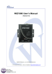
WIZ140SR/WIZ145SR User Manual ( Version 2.0 ) ©2012 WIZnet Co., Ltd. All Rights Reserved. ☞ For more information, visit our website at http://www.wiznet.co.kr WIZ140SR/WIZ145SR Datasheet (WIZnet Co., Ltd.) Document Revision History Date Revision Changes 2010-07-14 1.0 Released 2012-06-15 2.0 Modify the error sentence ( P3, P8, P10, P13, P16 ) COPYRIGHT NOTICE Copyright 2012 WIZnet Co., Ltd. All Rights Reserved. Technical Support: [email protected] Sales & Distribution: [email protected] For more information, visit our website at http://www.wiznet.co.kr WIZ140SR/WIZ145SR Datasheet (WIZnet Co., Ltd.) Contents 1. Introductions ................................................................................................................... 1 1.1 Main Features ........................................................................................................... 1 1.2 Specifications ............................................................................................................ 2 2. Getting Start ................................................................................................................... 3 2.1 Install Hardware......................................................................................................... 3 2.2 Configuration Tool Installation..................................................................................... 3 Important Functions......................................................................................................... 4 3.1 Module Configuration thru TCP/IP .............................................................................. 4 3.2 Module Configuration thru Serial command ................................................................ 4 3.2.1 Serial command Format ................................................................................... 4 3.2.2 Command code(Direction: Serial device -> MODULE) ....................................... 5 3.2.3 Reply code(Direction: WIZ140SR/WIZ145SR -> Serial device) .......................... 7 3.2.4 Example .......................................................................................................... 8 3.2.4.1 Command for changing the IP address of the module to 192.168.1.2 ....... 8 3.2.4.2 Command for setting the Domain Name of Channel #1 ............................ 8 3.2.4.3 Command for reading the Local Port Number of Channel #3, when the value is 5000 ..................................................................................................... 8 3.3 IP Accuisition Mode (Static, DHCP, PPPoE) Setting Function....................................... 8 3.3.1 Static ............................................................................................................... 8 3.3.2 DHCP .............................................................................................................. 9 3.3.3 PPPoE .......................................................................................................... 10 3.4 Connection Mode (Server, Client, UDP) Setting Function .......................................... 10 3.4.1 Server Mode .................................................................................................. 10 3.4.2 Client Mode ................................................................................................... 11 3.5 DNS Setting Function .............................................................................................. 11 3.6 Real-time Debug Function........................................................................................ 12 3.7 Data Packetizing Function ........................................................................................ 13 3.7.1 Character....................................................................................................... 13 3.7.2 Size ............................................................................................................... 14 3.7.3 Time .............................................................................................................. 15 3.7.4 Compound Settings........................................................................................ 15 3.8 Inactivity Time Function............................................................................................ 16 3.9 Firmware uploading thru TCP/IP............................................................................... 16 3.10 Log Data save and report function .......................................................................... 17 3.10.1 Log Data ...................................................................................................... 17 3.10.1.1 Log Data Frame ................................................................................. 17 3.10.1.2 Code & Parameter .............................................................................. 17 3.11 TCP Connection Status Function ............................................................................ 19 Demo............................................................................................................................ 20 4.1 Operate in Server mode ........................................................................................... 20 4.1.1 Composition................................................................................................... 20 4.1.2 Operation Order ............................................................................................. 20 3 4 WIZ140SR/WIZ145SR Datasheet (WIZnet Co., Ltd.) Figures IMAGE 1 CONFIGURATION TOOL ................................................................................................................... 3 IMAGE 2 SERIAL COMMAND FRAME FORMAT .............................................................................................. 4 IMAGE 3 SERIAL COMMAND EXAMPLE #1 .................................................................................................... 8 IMAGE 4 SERIAL COMMAND EXAMPLE #2 .................................................................................................... 8 IMAGE 5 SERIAL COMMAND EXAMPLE #3 .................................................................................................... 8 IMAGE 6 DEBUGGING FROM DEBUG SERIAL PORT ..................................................................................... 13 IMAGE 7 LOG DATA FRAME ........................................................................................................................ 17 IMAGE 8 CONSOLE SCREEN DURING MODULE BOOTING PROCESS ........................................................... 22 IMAGE 9 SCREEN AFTER CONNECTING TO MODULE WITH TCP/IP ............................................................ 23 IMAGE 10 CONSOL SCREEN AFTER TCP CONNECTION............................................................................. 24 Tables TABLE 1 SPECIFICATIONS ............................................................................................................................. 2 TABLE 2 SERIAL COMMAND CODE TABLE .................................................................................................... 7 TABLE 3 SERIAL COMMAND REPLY CODE TABLE ........................................................................................ 7 TABLE 4 LOG DATA CODE & PARAMETER TABLE ......................................................................................... 18 WIZ140SR/WIZ145SR Datasheet (WIZnet Co., Ltd.) 1. Introductions 1.1 Main Features Support 4 Serial port Connect with the Serial Device directly Adding network function simply and quickly Providing Firmware customization High system stability and reliability by using W5300 Easy and powerful configuration tool program Support DHCP and DNS function Support static as well as dynamic IP setting 10/100 Mbps Ethernet interface, Max 115,200bps serial interface RoHS compliant WIZ140SR/WIZ145SR Datasheet 1 1.2 Specifications WIZ140SR MCU TCP/IP PHY Architecture WIZ145SR ARM-based 32-bit MCU W5300 Included in W5300 10/100Mbps Ethernet Auto negotiation (Full-duplex and Half-duplex) Auto MDI/MDIX Serial Serial Data RS-232C Interface TTL Signals TXD, RXD, RTS, CTS, GND Parameters Parity : None, Odd, Even Data bits : 7, 8 bit Port Flow control : None, RTS / CTS, XON / XOFF Speed Up to 115,200bps Serial Interface TTL Debug Signals TXD, RXD Port Parameters Parity : None Data bits : 8 bit Flow control : None Speed 115,200bps Dimensions 48.26mm ( Include connector size ) 16.2mm Pin header Connector x 35.56mm x 48.26mm x 61.4mm x 24.7mm 2.54mm Pitch Pin-header, 14Pin (1x14) 2.54mm Pitch Pin-header, 28Pin (2x14) RJ-45 Connector Input voltage Power consumption Temperature Humidity None 1 RJ-45 Connector DC 3.3V Under 200mA 0°C ~ 70°C (Operation), -40°C ~ 85°C (Storage) 10 ~ 80% Table 1 Specifications WIZ140SR/WIZ145SR Datasheet 2 2. Getting Start 2.1 Install Hardware You prepared WIZ140SR Module or WIZ145SR module with Test board. STEP1: Drop the WIZ140SR/WIZ145 Module in WIZ140SR/WIZ145SR Test Board. STEP2: Connect Ethernet cable to RJ-45 connector on the Test Board STEP3: Connect PC and Test Board using Serial Cable. STEP4: If you check Debugging message from debug serial port, you connect PC and Test Board using Serial Cable. STEP5: connect to the power *1. Boot selection pin is open, when working normal mode. *2. H/W Trigger switch is OFF. 2.2 Configuration Tool Installation Start the Configuration Tool Installation program, which can be downloaded from the WIZnet home page. The captured screen of the Configuration tool is as shown below. Image 1 Configuration tool WIZ140SR/WIZ145SR Datasheet 3 3 Functions 3.1 Module Configuration thru TCP/IP Basic Information for modules, WIZ140SR and WIZ145SR, can be set by using TCP/IP network. ① Connect the module and PC, that has ConfigTool.exe installed, to the network of same subnet and turn on power. ② Click the button from the Tool program, then, all modules that are connected to the local network will display. ③ Use the Configuration Tool to modify the settings of each module. Specific modification steps are explained after 3.3 of this document 3.2 Module Configuration thru Serial command This function is used to modify the settings of the module by using Serial port. Connect the cable to the module’s Channel #1 serial port and switch the HW Trigger SW’s pin to ‘ON.” Then, Serial command mode is accessed. ※ Caution! Once Serial command mode is activated, the connected TCP socket is disconnected, therefore, data exchange through the data channel is not possible. 3.2.1 Serial command Format 1 Byte 4 Bytes (0 ~ 32 Bytes) 1Byte STX1 Command code Parameter ETX2 Image 2 Serial Command Frame Format STX : ‘<’ (Hex code: 0x3C) ETX : ‘>’ (Hex code: 0x3E) WIZ140SR/WIZ145SR Datasheet 1 2 4 3.2.2 Command code(Direction: Serial device -> MODULE) General Info Code Parameter Comments R_PC None Get Product Code R_IP None Get Local IP Address W_IP xxx.xxx.xxx.xxx Set Local IP Address R_SN None Get Subnet Mask W_SN xxx.xxx.xxx.xxx Set Subnet Mask R_GW None Get Gateway Address W_GW xxx.xxx.xxx.xxx Set Gateway Address R_FW None Get Firmware Version R_DB None Get Debug mode value W_DB 0: Disable Set Debug mode value 1 : Enable R_MD None Get IP setting mode value W_MD 0: Static Set IP setting mode value 1: DHCP 2 : PPPoE R_CM None Get Serial command mode type W_CM 0: H/W trigger Set Serial command mode type 1: S/W trigger Channel Info R_SC None Get Serial command mode character W_SC xxxxxx Set Serial command mode character R_DS None Get DNS Server IP Address W_DS xxx.xxx.xxx.xxx Set DNS Server IP Address W_XX None Reboot module RnSM None Get Socket operation mode n : channel number( 0 ~ 3) WnSM 0: TCP Server Set Socket operation mode 1: TCP Client n : channel number( 0 ~ 3) 2: Mixed RnCS None Get Socket connection state n : channel number( 0 ~ 3) RnDM None Get DNS mode value n : channel number( 0 ~ 3) WIZ140SR/WIZ145SR Datasheet 5 WnDM RnUM 0: Disable Set DNS mode value 1: Enable n : channel number( 0 ~ 3) None Get UDP mode value n : channel number( 0 ~ 3) WnUM RnSI 0: Disable Set UDP mode value 1: Enable n : channel number( 0 ~ 3) None Get Remote Peer’s IP Address n : channel number( 0 ~ 3) WnSI xxx.xxx.xxx.xxx Set Remote Peer’s IP Address n : channel number( 0 ~ 3) RnLP None Get Local port number n : channel number( 0 ~ 3) WnLP 0 ~ 65535 Set Local port number n : channel number( 0 ~ 3) RnSP None Get Remote Peer’s port number n : channel number( 0 ~ 3) WnSP 0 ~ 65535 Set Remote Peer’s port number n : channel number( 0 ~ 3) RnSD None Get Remote Peer’s Domain name n : channel number( 0 ~ 3) WnSD xxxxxxxxxxxxxxx(Variable) Set Remote Peer’s Domain name n : channel number( 0 ~ 3) RnBU None Get Serial configuration value(Baud rate, data bit, parity and flow control) n : channel number( 0 ~ 3) WnBU xxxx Set Serial configuration value(Baud [Baud] rate, data bit, parity and flow control) 0 115200 1 57600 2 38400 4 19200 4 9600 5 4800 6 2400 7 1200 n : channel number( 0 ~ 3) 4Bytes : [Baud][Data][Parity][Flow] [Data] 0 7bit 1 8bit [Parity] WIZ140SR/WIZ145SR Datasheet 0 1 2 None Odd Even 6 [Flow Control] RnOC 0 1 2 None Xon/Xoff RTS/CTS None Get Data Packing Condition ‘Char’ n : channel number( 0 ~ 3) WnOC xx Set Data Packing Condition Char n : channel number( 0 ~ 3) ex) if value is 0x0D, then ‘0’’D’ RnOS None Get Data Packing Condition ‘Size’ WnOS 0 ~ 255 Set Data Packing Condition ‘Size’ n : channel number( 0 ~ 3) RnOT None Get Data Packing Condition ‘Time’ n : channel number( 0 ~ 3) WnOT 0 ~ 65535 Set Data Packing Condition ‘Time’ n : channel number( 0 ~ 3) RnOI None Get Inactivity Time value n : channel number( 0 ~ 3) WnOI 0 ~ 65535 Set Inactivity Time value n : channel number( 0 ~ 3) Table 2 Serial Command Code Table 3.2.3 Reply code(Direction: WIZ140SR/WIZ145SR -> Serial device) Reply Meaning E Serial command mode Start S Command Success F Command Fail 1 Invalid command 2 Invalid parameter Table 3 Serial Command Reply Code Table WIZ140SR/WIZ145SR Datasheet 7 3.2.4 Example 3.2.4.1 Command for changing the IP address of the module <W_IP192.168.1.2> Users’ Serial Device <S> WIZ140SR/WIZ145SR <W_XX>3 Image 3 Serial Command Example #1 3.2.4.2 Command for setting the Domain Name of Channel #1 < W1SDwww. wiznetexam.com > Users’ Serial Device <S> WIZ140SR/WIZ145SR <W_XX> Image 4 Serial Command Example #2 3.2.4.3 Command for reading the Local Port Number of Channel #3 <R3LP> Users’ Serial Device <S5000> WIZ140SR/WIZ145SR Image 5 Serial Command Example #3 3.3 IP Acquisition Mode (Static, DHCP, PPPoE) Setting Function This function is for setting how the module’s IP address is going to be acquired. 3.3.1 Static The Static IP address mode is used when assigning static IP address. When Permanent IP address is assigned by the network manager, ① First, click the button to find module that is connected to the network. In case of Set command, command W_XX must be sent at the end in order for the module to be configured. WIZ140SR/WIZ145SR Datasheet 3 8 ② Select the module that the value will be assigned from the ListBox, which is shown at the left of the screen. ③ Select Static for the IP address mode, ④ Enter the assigned values for IP address, Subnet mask, and Gateway address, ⑤ Click . 3.3.2 DHCP The DHCP IP address mode is used when equipment that assign dynamic IP, like routers are connected. ① ② First, click the button and find the module that is connected to the network. Select the module that the value will be assigned from the ListBox, which is shown at the left of the screen. ③ Select DHCP for the IP address mode, ④ Click . ※ When there is not a DCHP server, the DHCP process fails. When the DHCP process fails, booting completes with the existing network information after a period of time.. WIZ140SR/WIZ145SR Datasheet 9 3.3.3 PPPoE The PPPoE IP address mode is used for setting the environment which communicate based on PPPoE, like ADSL modem. ① First, click the ② Select the module that the value will be assigned from the ListBox, which is shown at button and find the module that is connected to the network. the left of the screen, ③ Select PPPoE for the IP address mode, ④ Enter values of the ID and PW for PPPoE access. ⑤ Lastly, click . 3.4 Connection Mode (Server, Client, UDP) Setting Function 3.4.1 Server Mode ① First, click the ② Select the module that the value will be assigned from the ListBox, which is shown at button and find the module that is connected to the network the left of the screen ③ Select Server for Connection mode, ④ “Enter the Local Port value for Listen in the “Internet Connectivity Information box.” WIZ140SR/WIZ145SR Datasheet 10 ⑤ Lastly, click ※ When Server mode is used, Remote IP address and Remote Port has no use. . 3.4.2 Client Mode ① ② First, click the button and find the module that is connected to the network Select the module that the value will be assigned from the ListBox, which is shown on the left of the screen ③ Select Client for Connection mode ④ Enter the IP and Port number from the “Internet Connectivity Information box” into the “Remote IP address” and “Remote Port.” Enter the Module’s communication Port number into Local Port ⑤ Lastly, click . ※ When Client mode is being used, the module continuously attempts connection to Remote IP address and Remote Port after booting. 3.5 DNS Setting Function This function is used when Domain name is used due to server’s frequent change and non-fixed server IP. If the server address is the Domain name instead of the IP address, this function must be used. ① First, click button, and find the module that is connected to the network WIZ140SR/WIZ145SR Datasheet 11 . ② Select the module that the value will be assigned from the ListBox, which is shown on the left of the screen, ③ Enter IP into DNS Server IP. ④ Check the box for “DNS mode,” and enter the Server Domain Name. ⑤ Enter the Port numbers for server and module. ⑥ Lastly, click . 3.6 Real-time Debug Function . This function is used to check on the motion of the module when the module is attached to the system during the system development process. The Console port is used to read the debug code of the module in real time. WIZ140SR/WIZ145SR Datasheet 12 Image 6 Debugging from Debug serial port 3.7 Data Packet Function This function is used to determine whether the data read from the serial port is going to be sent to the remote server or client in some kind of Ethernet packet unit. 3.7.1 Character The data is buffered in the internal memory of the module until the specific characters are received. Once the specific characters are received, the buffered data are made into one Ethernet packet and are sent to the remote system. WIZ140SR/WIZ145SR Datasheet 13 This function is appropriate when the end of data frame that the serial port sends to the module ends with specific characters. ① First, click button, and find the module that is connected to the network. Select the module that the value will be assigned from the ListBox, which is shown on the left of the screen, ② Enter the ASCII value of the character in the form of HEX code in the “Character” section of the “Data Packing Condition” box. (Enter 0x00 for Disable) ③ Lastly, click . 3.7.2 Size This function is used when data is buffered in the serial port until the received data amounts to a specific byte size, and when the received data amounts up to the specific byte size, the buffered data are made into one Ethernet packet and sent to the remote system. This function is appropriate when size of the data, which is sent from the serial port to the module, is fixed. ① First, click ② Select the module that the value will be assigned from the ListBox, which is shown on button, and find the module that is connected to the network. the left of the screen ③ Enter the wanted size in the “Size” section of the “Data Packing Condition” box. (Enter 0 for Disable) ④ Lastly, click . WIZ140SR/WIZ145SR Datasheet 14 3.7.3 Time If there is not any new data during designated time, all data in the serial buffer is converted to Ethernet packet. If new data is received, the time is re-calculated and the received data is saved in the serial buffer. Time condition can be utilized when the serial data size is variable and has no ending character, but needs to be delivered in frame unit. (If the value is ‘0’, option is not used) ① First, click button, and find the module that is connected to the network. Select the module that the value will be assigned from the ListBox, which is shown on the left of the screen, ② Enter the wanted time information in the “Time” section of the “Data Packing Condition” box. (Enter 0 for Disable) ③ Lastly, click . 3.7.4 Compound Settings Among the three functions explained above, two or more can be mixed for use. WIZ140SR/WIZ145SR Datasheet 15 3.8 Inactivity Time Function This function is used to forcibly disconnect the communication connection (TCP socket) when there are no data exchange with the remote system for a certain period of time. ① button, and find the module that is connected to the network. First, click select the module that the value will be assigned from the ListBox, which is shown on the left of the screen, ② Enter the wanted time information in the “Inactivity Time” section of the “Disconnect Condition” box. (Enter 0 for Disable) ③ Lastly click . 3.9 Firmware uploading thru TCP/IP This function is used for updating the module’s Firmware ① First, click ② Select the module that the value will be assigned from the ListBox, which is shown on button, and find the module that is connected to the network. the left of the screen, ③ Click ④ Lastly, click ※ In order to use the Firmware upload function, an IP address for communication with the to select the binary file for update. . module must be set. Make sure to ping test to check the module is able to communicate. WIZ140SR/WIZ145SR Datasheet 16 3.10 Log Data save and report function The module saves it operation and results in its memory; this function can load and read when the user wishes to. This function can be used to check on the problems when the communication with the remote system is not good. For example, things like, whether the serial device sent the data, or whether the module was down, or whether there was a problem with the communication circuit (ISP communication circuit), can be checked. 3.10.1 Log Data 3.10.1.1 Log Data Frame Byte 1 Byte 2 Byte 3 Byte 4 Time Information[0:3] Byte 5 Byte 6 Byte 7 Byte 8 CODE PARM1 PARM2 PARM3 Log time Log value Image 7 Log Data Frame 3.10.1.2 Code & Parameter Code Value(4Byte) Meaning CODE PARM1 PARM2 PARM3 0x01 0x00 0x00 0x00 Operation succeeded 0x02 0x00 0x00 0x00 Operation failed 0x10 0x00 0x00 0x00 Reboot 0x11 0x00 0x00 0x00 DHCP init start 0x12 0x00 0x00 0x00 DNS query start 0x13 0x00 0x00 0x00 PPPoE init start 0x20 n 0x00 0x00 Socketn Initialized WIZ140SR/WIZ145SR Datasheet Remarks n: Socket # 17 0x21 n 0x00 0x00 Socketn Connecting 0x22 n 0x00 0x00 Socketn Listen 0x23 n Size_H4 Size_L5 Socketn lbytes data sent 0x24 n Size_H Size_L Socketn lbytes data receved 0x25 n 0x00 0x00 Socketn Closed 0x30 0x00 0x00 0x00 FW Upload requested 0x31 0x00 0x00 0x00 FW Upload completed 0x32 0x00 0x00 0x00 FW Upload failed 0x40 0x00 0x00 0x00 Config Data Writing 0x41 0x00 0x00 0x00 Config Data Reading Table 4 Log data code & parameter Table Sent from Ethernet or higher byte among data size Lower byte among data size WIZ140SR/WIZ145SR Datasheet 4 5 18 3.11 TCP Connection Status Function This function is used to check the connection status for each channel of the module. This can be checked through the H/W pin. If the value of the Pin is Low, the status is “Connected”. If the value of the Pin is HIGH, the status is “Disconnected”. ※ In case of Serial command mode, all communication channels are forcibly cleared; and the Connection status can’t be checked through the serial. WIZ140SR/WIZ145SR Datasheet 19 4 Test 4.1 Operate in Server mode 4.1.1 Composition Module PC IP address(Static) 192.168.123.193 IP address 192.168.123.101 Ch# 1 Port number 5000 Port number auto Ch#1 Socket mode Server Socket mode Client Ch#1 Packing cond. Time 10ms Ch#2 Port number 5001 Port number auto Ch#2 Socket mode Server Socket mode Client Ch#2 Packing cond. Time 10ms Ch#3 Port number 5002 Port number auto Ch#3 Socket mode Server Socket mode Client Ch#3 Packing cond. Disable Ch#4 Port number 5003 Port number auto Ch#4 Socket mode Server Socket mode Client Ch#4 Packing cond. Size 10 4.1.2 Operation Order ① First, click ② Select the module that the value will be assigned from the ListBox, which is shown on button, and find the module that is connected to the network. the left of the screen, ③ Channel #1 Configurations WIZ140SR/WIZ145SR Datasheet 20 ④ Channel #2 Configurations ⑤ Channel #3 Configurations ⑥ Channel #4 Configurations WIZ140SR/WIZ145SR Datasheet 21 ⑦ Click ⑧ Apply the new values of the module and reboot. Image 8 Console screen during module booting process ⑨ Run the Socket communication program, and attempt connection. WIZ140SR/WIZ145SR Datasheet 22 Image 9 Screen after connecting to module with TCP/IP ⑩ Connection with module can be checked by using the Debug terminal. WIZ140SR/WIZ145SR Datasheet 23 Image 10 Consol screen after TCP Connection ⑪ Repeat these steps with other channels to access, and data communication is enable. WIZ140SR/WIZ145SR Datasheet 24