1
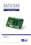
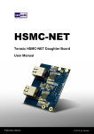
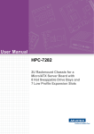
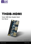
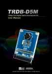
THDB-ADA User Manual 1 www.terasic.com October 19, 2015 CONTENTS Chapter 1 About the Kit................................................................................. 3 1.1 Kit Contents .......................................................................................................................................... 3 1.2 Connectivity ......................................................................................................................................... 4 1.3 Getting Help ......................................................................................................................................... 9 Chapter 2 Architecture of the ADA .............................................................. 10 Chapter 3 Using the ADA ............................................................................. 11 3.1 Digital-to-Analog Converter................................................................................................................ 11 3.2 Analog-to-Digital Converter ................................................................................................................ 12 3.3 Board Components.............................................................................................................................. 13 3.4 Clock Circuitry ................................................................................................................................... 18 Chapter 4 ADA Demonstration .................................................................... 19 4.1 Arbitrary Waveform Generator ............................................................................................................ 19 4.2 A/D and D/A Converter Performance Evaluation ................................................................................. 21 Chapter 5 Appendix ..................................................................................... 26 5.1 The Revision History .......................................................................................................................... 26 5.2 Always Visit Terasic Webpage for New Applications ........................................................................... 26 THDB-ADA User Manual 2 www.terasic.com October 19, 2015 Chapter 1 About the Kit The THDB_ADA (ADA) daughter board is designed to provide DSP solution on DE series and Cyclone III Starter Kit, or other boards with HSMC or GPIO interface. It is equipped with one ADC (Analog-to-Digital Converter) and DAC (Digital-to-Analog Converter) each, to provide dual-channel ports. This chapter provides users key information about the kit. 1.1 Kit Contents Figure 1-1 and Figure 1-2 show the picture of the ADA-HSMC and ADA-GPIO package, respectively. The package includes: 1. The Terasic Analog-to-Digital and Digital-to-Analog (ADA) board 2. Complete reference design with source code Figure 1-1 ADA-HSMC THDB-ADA User Manual 3 www.terasic.com October 19, 2015 Figure 1-2 ADA-GPIO 1.2 Connectivity There are two models available, ADA-GPIO and ADA-HSMC, which offer the compatibility of connection to DE2/DE1/DE0/DE2-70 and TR4/DE4/DE3/ DE2-115/DE2i-150/SoCkit/DE1-SoC/Cyclone V Starter Kit/Cyclone III Starter Kit, respectively. THDB-ADA User Manual 4 www.terasic.com October 19, 2015 Figure 1-3 Connect ADA-GPIO with DE2-70 Figure 1-4 Connect ADA-HSMC with Cyclone III Starter Kit THDB-ADA User Manual 5 www.terasic.com October 19, 2015 Figure 1-5 Connect ADA-HSMC with DE3 (HSTC conector D) (Note, an HFF or SFF adapter card is required in its connection part of the bundled package on the DE3) Figure 1-6 Connect ADA-HSMC with DE4 (HSMC port A) (Note, an HMF2 adapter card is required in its connection part of the bundled package on the DE4) THDB-ADA User Manual 6 www.terasic.com October 19, 2015 Figure 1-7 Connect ADA-HSMC with DE2-115 Figure 1-8 Connect ADA-HSMC with C5G(Cyclone V GX Starter Kit) THDB-ADA User Manual 7 www.terasic.com October 19, 2015 Figure 1-9 Connect ADA-HSMC with TR4 (HSMC port A) Figure 1-10 Connect ADA-HSMC with DE2i-150 THDB-ADA User Manual 8 www.terasic.com October 19, 2015 Figure 1-11 Connect ADA-GPIO with DE1-SoC Figure 1-12 Connect ADA-HSMC with SoCkit 1.3 Getting Help This chapter describes the architecture of the tPad including block diagram and components. Email to [email protected] Taiwan & China: +886-3-575-0880 Korea : +82-2-512-7661 Japan: +81-428-77-7000 THDB-ADA User Manual 9 www.terasic.com October 19, 2015 Chapter 2 Architecture of the ADA This chapter will illustrate the architecture of the ADA including device features and applications. The feature set of the ADA is listed below: 1. Dual AD channels with 14-bit resolution and data rate up to 65 MSPS 2. Dual DA channels with 14-bit resolution and data rate up to 125 MSPS 3. Dual interfaces include HSMC and GPIO, which are fully compatible with Cyclone III Starter Kit and DE1/DE2/DE2_70/DE2_115/DE3/DE4, respectively 4. Clock sources include oscillator 100MHz, SMA for AD and DA each, and PLL from either HSMC or GPIO interface 5. AD converter analog input range 2V p-p range. 6. DA converter output voltage range 2V p-p range. 7. DA and AD converters do not support DC signaling THDB-ADA User Manual 10 www.terasic.com October 19, 2015 Chapter 3 Using the ADA This chapter illustrates some special features of the ADA including interleaved data mode for digital-to-analog converter and multiplexed data mode for analog-to-digital converter. 3.1 Digital-to-Analog Conver ter This section will describe the interleaved data mode for D/A converter of the ADA. The DAC integrates two 14-bit TxDAC+ cores with dual-port input, while supporting refresh rate up to 125 MSPS. The dual-channel makes it capable of transmitting different data to two separate ports with different update rates. But it is the interleaving mode that makes it special, especially for processing I and Q data in communication applications. The input data stream is demuxed into its original I and Q data and latched. In the next phase they are converted by the two TxDAC+ cores and updated at half the input data rate. Figure 3-1 shows the timing of DAC in interleaved mode. THDB-ADA User Manual 11 www.terasic.com October 19, 2015 Figure 3-1 Interleaved Mode Timing 3.2 Analog-to-Digital Conver ter This section will describe the multiplexed data mode for A/D converter of the ADA. The ADC features dual sample-and-hold amplifiers with data rate up to 65 MSPS at the resolution of 14-bit. Its dual-channel inputs can also operate as two independent ports with different clock rates. Based on the state of the MUX option, multiplexed data output can be achieved by mixing data from the dual ports and the data rate is twice the sample rate. Figure 3-2 shows the multiplexed data format using the channel A output and the same clock tied to clock inputs of port A and B, and the selection of MUX option. THDB-ADA User Manual 12 www.terasic.com October 19, 2015 Figure 3-2 Multiplexed Data Format using the Channel A Output 3.3 Boar d Components This section illustrates the detailed information of the connector interfaces and pin mapping tables of the ADA daughter board. The clock, control, and data signals of the ADA daughter board are connected to the HSMC or GPIO connector. The tables below list the pin no. of the HSMC and GPIO connector. Pin No. Schematic GPIO 0 (J7) Name 1 2 3 4 5 6 7 8 9 10 11 12 13 14 15 16 17 18 ADC_OTRA ADC_DB0 ADC_OTRB ADC_DB1 ADC_DB2 ADC_DB4 ADC_DB3 ADC_DB5 ADC_DB6 ADC_DB8 GND ADC_DB7 ADC_DB9 ADC_DB10 ADC_DB12 ADC_DB11 ADC_DB13 THDB-ADA User Manual Description A/D Out-of-Range Indicator Channel A A/D Data Output bit 0 Channel B A/D Out-of-Range Indicator Channel B A/D Data Output bit 1 Channel B A/D Data Output bit 2 Channel B A/D Data Output bit 4 Channel B A/D Data Output bit 3 Channel B A/D Data Output bit 5 Channel B A/D Data Output bit 6 Channel B A/D Data Output bit 8 Channel B Ground A/D Data Output bit 7 Channel B A/D Data Output bit 9 Channel B A/D Data Output bit 10 Channel B A/D Data Output bit 12 Channel B A/D Data Output bit 11 Channel B A/D Data Output bit 13 Channel B 13 www.terasic.com October 19, 2015 19 20 21 22 23 24 25 26 27 28 29 30 31 32 33 34 35 36 37 38 39 40 PLL_OUT_ADC0 ADC_DA0 PLL_OUT_ADC1 ADC_DA1 ADC_DA2 ADC_DA4 ADC_DA3 ADC_DA5 ADC_DA6 ADC_DA8 VCC3 GND ADC_DA7 ADC_DA9 ADC_DA10 ADC_DA12 ADC_DA11 ADC_DA13 POWER_ON ADC_OEB ADC_OEA PLL Clock input Channel A A/D Data Output bit 0 Channel A PLL Clock input Channel B A/D Data Output bit 1 Channel A A/D Data Output bit 2 Channel A A/D Data Output bit 4 Channel A A/D Data Output bit 3 Channel A A/D Data Output bit 5 Channel A A/D Data Output bit 6 Channel A A/D Data Output bit 8 Channel A 3.3V Power Ground A/D Data Output bit 7 Channel A A/D Data Output bit 9 Channel A A/D Data Output bit 10 Channel A A/D Data Output bit 12 Channel A A/D Data Output bit 11 Channel A A/D Data Output bit 13 Channel A Power-Down Function for Channel A & B A/D Output Enable Pin for Channel B A/D Output Enable Pin for Channel A Pin No. Schematic GPIO 1 (J8) Name 1 2 3 SMA_DAC4 DAC_DA13 OSC_SMA_ADC4 4 5 6 7 8 9 10 11 12 13 14 15 16 17 DAC_DA12 DAC_DA11 DAC_DA9 DAC_DA10 DAC_DA8 DAC_DA7 DAC_DA5 SMA D/A External Clock Input (J5) D/A Data bit 13 Channel A SMA A/D External Clock Input (J5) or 100MHz Oscillator Clock Input D/A Data bit 12 Channel A D/A Data bit 11 Channel A D/A Data bit 9 Channel A D/A Data bit 10 Channel A D/A Data bit 8 Channel A D/A Data bit 7 Channel A D/A Data bit 5 Channel A GND DAC_DA6 DAC_DA4 DAC_DA3 DAC_DA1 DAC_DA2 Ground D/A Data bit 6 Channel A D/A Data bit 4 Channel A D/A Data bit 3 Channel A D/A Data bit 1 Channel A D/A Data bit 2 Channel A THDB-ADA User Manual Description 14 www.terasic.com October 19, 2015 18 19 20 21 22 23 24 25 26 27 28 29 30 31 32 33 34 35 36 37 38 39 40 DAC_DA0 PLL_OUT_DAC0 DAC_WRTA PLL_OUT_DAC1 DAC_DB13 DAC_DB12 DAC_DB11 DAC_DB9 DAC_DB10 DAC_DB8 VCC3 GND DAC_DB5 DAC_DB7 DAC_DB4 DAC_DB6 DAC_DB1 DAC_DB3 DAC_DB0 DAC_DB2 DAC_WRTB DAC_MODE D/A Data bit 0 Channel A PLL Clock Input Channel A Input Write Signal Channel A PLL Clock Input Channel B D/A Data bit 13 Channel B D/A Data bit 12 Channel B D/A Data bit 11 Channel B D/A Data bit 9 Channel B D/A Data bit 10 Channel B D/A Data bit 8 Channel B 3.3V Power Ground D/A Data bit 5 Channel B D/A Data bit 7 Channel B D/A Data bit 4 Channel B D/A Data bit 6 Channel B D/A Data bit 1 Channel B D/A Data bit 3 Channel B D/A Data bit 0 Channel B D/A Data bit 2 Channel B Input Write Signal Channel B Mode Select. 1=dual port, 0=interleaved Pin No. Pin No. Pin No. Schematic ADA HSMC HSMC HSTC (DE3 Name (J9) Description only) 3 157 3 4 158 4 5 155 5 6 156 6 PLL_OUT_AD C1 AD_OTRB 9 151 9 AD_DB0 10 152 10 AD_DA0 11 149 11 AD_DB1 12 150 12 AD_DA1 THDB-ADA User Manual PLL_OUT_AD C0 AD_OTRA 15 PLL Clock Input Channel A A/D Out-of-Range Indicator Channel A PLL Clock input Channel B A/D Out-of-Range Indicator Channel B A/D Data Output bit 0 Channel B A/D Data Output bit 0 Channel A A/D Data Output bit 1 Channel B A/D Data Output bit 1 Channel A www.terasic.com October 19, 2015 15 145 15 AD_DB2 16 146 16 AD_DA2 17 143 17 AD_DB3 18 144 18 AD_DA3 21 139 21 AD_DB4 22 140 22 AD_DA4 23 137 23 AD_DB5 24 138 24 AD_DA5 27 133 27 AD_DB6 28 134 28 AD_DA6 29 131 29 AD_DB7 30 132 30 AD_DA7 33 127 33 AD_DB8 34 128 34 AD_DA8 35 125 35 AD_DB9 36 126 36 AD_DA9 39 121 39 AD_DB10 40 122 40 AD_DA10 41 119 41 AD_DB11 42 120 42 AD_DA11 45 115 45 AD_DB12 46 116 46 AD_DA12 47 113 47 AD_DB13 THDB-ADA User Manual 16 A/D Data Output bit 2 Channel B A/D Data Output bit 2 Channel A A/D Data Output bit 3 Channel B A/D Data Output bit 3 Channel A A/D Data Output bit 4 Channel B A/D Data Output bit 4 Channel A A/D Data Output bit 5 Channel B A/D Data Output bit 5 Channel A A/D Data Output bit 6 Channel B A/D Data Output bit 6 Channel A A/D Data Output bit 7 Channel B A/D Data Output bit 7 Channel A A/D Data Output bit 8 Channel B A/D Data Output bit 8 Channel A A/D Data Output bit 9 Channel B A/D Data Output bit 9 Channel A A/D Data Output bit 10 Channel B A/D Data Output bit 10 Channel A A/D Data Output bit 11 Channel B A/D Data Output bit 11 Channel A A/D Data Output bit 12 Channel B A/D Data Output bit 12 Channel A A/D Data Output bit 13 Channel B www.terasic.com October 19, 2015 48 114 48 AD_DA13 52 110 52 ADC_OEB 54 108 54 ADC_OEA 63 97 63 64 98 64 PLL_OUT_DA C0 SMA_DAC4 65 95 65 66 96 66 69 91 69 DA_MODE 71 72 75 76 77 78 81 82 83 84 87 88 89 90 93 94 95 96 99 100 101 102 105 106 107 108 111 112 113 89 90 85 86 83 84 79 80 77 78 73 74 71 72 67 68 65 66 61 62 59 60 55 56 53 54 49 50 47 71 72 75 76 77 78 81 82 83 84 87 88 89 90 93 94 95 96 99 100 101 102 105 106 107 108 111 112 113 DA_WRTA DA_WRTB DA_DA13 DA_DB13 DA_DA12 DA_DB12 DA_DA11 DA_DB11 DA_DA10 DA_DB10 DA_DA9 DA_DB9 DA_DA8 DA_DB8 DA_DA7 DA_DB7 DA_DA6 DA_DB6 DA_DA5 DA_DB5 DA_DA4 DA_DB4 DA_DA3 DA_DB3 DA_DA2 DA_DB2 DA_DA1 DA_DB1 DA_DA0 THDB-ADA User Manual PLL_OUT_DA C1 OSC_SMA_A DC4 17 A/D Data Output bit 13 Channel A A/D Output Enable Pin for Channel B A/D Output Enable Pin for Channel A PLL Clock Input Channel A SMA D/A External Clock Input (J5) PLL Clock Input Channel B SMA A/D External Clock Input (J5) or 100MHz Oscillator Clock Input Mode Select. 1=dual port, 0=interleaved Input Write Signal Channel A Input Write Signal Channel B D/A Data bit 13 Channel A D/A Data bit 13 Channel B D/A Data bit 12 Channel A D/A Data bit 12 Channel B D/A Data bit 11 Channel A D/A Data bit 11 Channel B D/A Data bit 10 Channel A D/A Data bit 10 Channel B D/A Data bit 9 Channel A D/A Data bit 9 Channel B D/A Data bit 8 Channel A D/A Data bit 8 Channel B D/A Data bit 7 Channel A D/A Data bit 7 Channel A D/A Data bit 6 Channel A D/A Data bit 6 Channel B D/A Data bit 5 Channel A D/A Data bit 5 Channel B D/A Data bit 4 Channel A D/A Data bit 4 Channel B D/A Data bit 3 Channel A D/A Data bit 3 Channel B D/A Data bit 2 Channel A D/A Data bit 2 Channel B D/A Data bit 1 Channel A D/A Data bit 1 Channel B D/A Data bit 0 Channel A www.terasic.com October 19, 2015 114 121 48 - 114 121 DA_DB0 POWER_ON 125 126 131 37 38 33 125 126 131 TDO_TDI TDO_TDI ID_I2CDAT 132 34 132 ID_I2CSCL D/A Data bit 0 Channel B Power-Down Function for Channel A & B JTAG JTAG I2C EEPROM serial address/data I/O I2C EEPROM serial clock 3.4 Clock Circuitr y This section describes the board’s clock inputs and outputs The clock sources available on the ADA daughter board include the 100MHz oscillator, external SMA clock input, and the PLL clock input from either HSMC or GPIO interface. Each channel of the AD and DA converter has the selection of choosing one of the clock sources (oscillator, SMA, and PLL) corresponding to the CLK SEL jumper of the ADA daughter board. Figure 3-3 ADA Clock System THDB-ADA User Manual 18 www.terasic.com October 19, 2015 Chapter 4 ADA Demonstration This chapter illustrates how to setup the ADA kit as an arbitrary waveform generator and evaluate the performance of A/D and D/A converter. 4.1 Arbitrar y Wavefor m Generator This section illustrates the implementation of random waveform generator using ADA. For Terasic mainboards with more than one HSMC connector, please refer to the table below for recommended connection. Terasic Mainboard DE3 Reference Figure 1-5 Connect ADA-HSMC with DE3 (HSTC conector D) DE4 Figure 1-6 Connect ADA-HSMC with DE4 (HSMC port A) TR4 Figure 1-9 Connect ADA-HSMC with TR4 (HSMC port A) Figure 4-1 is the complete setup of an ADA connected on DE3. Simply perform the following steps to display any pattern generated from PC-based GUI on an oscilloscope. The <path> is the directory where you copy the reference design folder, DE3_ADA, from CD to your PC. THDB-ADA User Manual 19 www.terasic.com October 19, 2015 Figure 4-1 Configuration Setup of Random Waveform Generator on DE3 Configuring the Board: 1. Connect the ADA-HSMC to DE3, as shown in Figure 4-2. 2. Use a SMA cable to connect DA-Channel B with an oscilloscope.. 3. For DAC B clock, add a jumper to JP5 with pins labeled PLL. 4. Use a USB cable to connect DE3 with PC 5. Power-on DE3 6. Open DE3_ADA.qsf from <path>\Demonstrations\DE3_ADA 7. Open Quartus Programmer from Tools -> Programmer 8. Press Start on the left-hand side. Starting PC-Based Graphical User Interface: 1. Open ADA_Utility.exe from <path>\ADA_Utility (If you are using Cyclone III Starter Board, please first run the QB3_ADA.bat file) THDB-ADA User Manual 20 www.terasic.com October 19, 2015 2. Use your mouse to draw a custom waveform from left to right. You may drag it or add more points to be sampled later on. 3. Set the frequency and the amplitude. 4. Press Start 5. Press Auto set on the oscilloscope if necessary. Figure 4-2 Pattern generated from DAC Channel-B is displayed on an oscilloscope 4.2 A/D and D/A Conver ter Perfor mance Evaluation This section illustrates the steps to evaluate the performance of A/D and D/A converter on ADA, based on the data collected from DE2-70. Similar steps can also be applied to DE2-115/DE2/DE1 or DE4/Cyclone III Starter Kit. The <path> is the directory where you copy the reference design folder, DE2_70_ADA, from CD to your PC. THDB-ADA User Manual 21 www.terasic.com October 19, 2015 Figure 4-3 Connect ADA-GPIO with DE2-70 Configuring the Board: 1. Connect the ADA-GPIO to DE2-70, as shown in Figure 4-3 2. Use a SMA cable to connect DA-Channel B with AD-Channel B. 3. Use a USB cable to connect DE2-70 with PC 4. Add appropriate jumpers for the mode and the clocks. a. For DAC B clock, add a jumper to JP5 with pins labeled PLL. b. For ADC B clock, add a jumper to JP2 with pins labeled PLL. c. For the selection of MUX option, add a jumper to JP3, between pins 1 and 2. 5. Power-on DE2-70 6. Open stp1.stp from <path>\Demonstrations\DE2_70_ADA, as shown in Figure 4-4. THDB-ADA User Manual 22 www.terasic.com October 19, 2015 Figure 4-4 Connect ADA-GPIO with DE2-70 Collecting Data Using the SignalTap II Logic Analyzer 1. Click “Program Device” after Hardware and Device are detected correctly. 2. Click “Run Analysis” and observe signals ADC_DB and comb, which shows attenuated and original combinations of two sine waves, respectively. 3. Choose File -> Create/Update -> Create SignalTap II List File and the Quartus II will generate the file stp1_auto_signaltap_0.txt in the project directory. If your Quartus II version is above 9.1, Please click ADC_DB and right click to select "Create SignalTap II List File" for outputting the List file. As show on the Figure 4-5. THDB-ADA User Manual 23 www.terasic.com October 19, 2015 Figure 4-5 Using Quartus 10.0 sp1 SignalTap II to generate the SignalTap II List File Analyzing the Data in the MATLAB Software 1. Start the MATLAB software. 2. Make sure the current directory is set to <path>\Demonstrations\DE2_70_ADA 3. If you are using the DE1 Board please copy the file nstp_plot.m from <path>\MATLAB to <path>\Demonstrations\DE1_ADA. 4. Type nstp_plot(‘stp1_auto_signaltap_0.txt’) at the MATLAB command prompt. The MATLAB will display normalized FFT plots of DAC B input and ADC B output similar to Figure 4-6 and Figure 4-7, respectively. THDB-ADA User Manual 24 www.terasic.com October 19, 2015 Figure 4-6 Normalized Spectral Plot of The 14-bit DAC B Input Data Figure 4-7 Normalized Spectral Plot of The 14-bit ADC B Output Data THDB-ADA User Manual 25 www.terasic.com October 19, 2015 Chapter 5 Appendix 5.1 The Revision Histor y Version Change Log V1.0.0 V1.1.0 V1.2.0 V1.2.1 V1.2.2 V1.2.3 V1.2.4 Initial Version (Preliminary) Add Default Demo for DE1 and DE2 DE4 and DE2-115 Demo added Change Figure Change ADC and DAC description Update Section 1.2 Connectivity Update Section 1.2 Connectivity 5.2 Always Visit Terasic Webpage for New Applications We will continually provide interesting examples and labs on our ADA webpage. Please visit www.terasic.com for more information. THDB-ADA User Manual 26 www.terasic.com October 19, 2015