1
RTE-V832-PC
USER’S MANUAL (Rev. 1.04)
RTE-V832-PC
USER’S MANUAL (Rev. 1.04)
Midas lab
RTE-V832-PC
USER’S MANUAL (Rev. 1.04)
REVISION HISTORY
Date
REV.
Chapter
Explanation of revision
September 10, 1998
1.02
First edition
February 2, 1999
1.03
11.1
Revised RFC set value
December 26, 2000
1.04
8.9
The interrupt input from the printer of PIC is changed into the rising edge
from high level. The board of revision newer than Rev.2.1 corresponds.
RTE-V832-PC
USER’S MANUAL (Rev. 1.03)
CONTENTS
1.
INTRODUCTION ................................................................................................................. 1
1.1. NUMERIC NOTATION ............................................................................................... 1
2.
FUNCTIONS ....................................................................................................................... 1
3.
MAJOR FEATURES ........................................................................................................... 2
4.
BASIC SPECIFICATIONS ................................................................................................... 2
5.
BOARD CONFIGURATION ................................................................................................. 3
5.1. RESET SWITCH (RESET) ......................................................................................... 3
5.2. POWER JACK (JPOWER) ......................................................................................... 3
5.3. SWITCH 1 (SW1)....................................................................................................... 3
5.4. SWITCH 2 (SW2)....................................................................................................... 4
5.5. SWITCH 3 (SW3)....................................................................................................... 4
5.6. SWITCH 4 (SW4)....................................................................................................... 5
5.7. LED .......................................................................................................................... 5
5.8. TEST PINS FOR ROM EMULATOR (JROM_EM) ........................................................ 5
5.9. CLOCK SOCKET (OSC1)........................................................................................... 6
5.10. ROM SOCKETS ........................................................................................................ 6
5.11. DMARQ0-, DMARQ1- SEPARATION JUMPER (JP1) .................................................. 6
5.12. TIMER CLOCK FREQUENCY SELECT JUMPER (JP2) ............................................... 6
5.13. AUDIO INPUT LEVEL SELECT JUMPERS (JP3, JP4, JP5, JP6).................................. 6
5.14. SERIAL CONNECTOR (JSIO1, JSIO2) ....................................................................... 7
5.15. PARALLEL CONNE CTOR (JPRT) .............................................................................. 8
5.16. AUDIO MINI-JACKS (JIN-R, JIN-L, JLINEOUT) ........................................................... 8
5.17. DEBUGGING CONNECTOR (JDCU) .......................................................................... 9
5.18. CPU CONNECTOR (JCPU-1, JCPU-2) ......................................................................10
5.19. EXTENSION BUS CONNECTOR (JEXT) ...................................................................11
6.
CONNECTION WITH THE HOST PC ..................................................................................12
6.1. STANDALONE USE OF THE BOARD (RS-232C CONNECTION) ...............................12
6.2. INSERTING IN PCI SLOT (PCI BUS CONNECTION ).................................................12
7.
HARDWARE REFERENCES ..............................................................................................13
7.1. MEMORY AND I/O MAP ...........................................................................................13
8.
I/O MAP.............................................................................................................................15
8.1. I/O LIST ...................................................................................................................15
8.2. DIPSW2 READ PORT (4500-0000H [READ ONLY]) ...................................................16
8.3. DIPSW1 READ PORT (4500-1000H [READ ONLY]) ...................................................16
8.4. 7-SEGMENT LED DISPLAY DATA OUTPUT PORT (4500-2000H [WRITE ONLY]) ......16
8.5. COMMAND REGISTER (4500-5000H [READ/WRITE]) ...............................................17
8.6. EXT-IO HIGH-ORDER ADDRESS SETTING REGISTER
(4500-6000H [READ/WRITE])....................................................................................17
8.7. UART/PRINTER (TL16PIR552) (4500-8000H TO 4500-A03EH) ..................................18
8.8. TIC (µPD71054) (4500-B000H TO 4500-B00CH) ........................................................19
8.9. INTERRUPT CONTR OLLER (PIC) (4500-D000H TO 4500-D018H) .............................20
i
RTE-V832-PC
USER’S MANUAL (Rev. 1.03)
8.10. AUDIO CONTROLLER (AUDCNT) (4580-0000H TO 4580-0010H, 4580-2000H) ..........21
8.11. µPD63310 REGISTER (4580-1000H TO 4580-100FH)................................................23
9.
INTERRUPTS AND DM A ...................................................................................................24
9.1. INTERRUPT.............................................................................................................24
9.2. USING NMI ..............................................................................................................24
9.3. DMA REQUEST .......................................................................................................25
10. EXT-BUS ...........................................................................................................................26
10.1. PIN ARRANGEMENT ...............................................................................................26
10.2. SIGNALS .................................................................................................................27
10.3. CONNECTION OF DATA BUS ..................................................................................28
10.3.1. 16-Bit Data Bus CPU (Reference) ................................................................28
10.3.2. 32-Bit Data Bus CPU (with V832).................................................................29
10.4. TIMING ....................................................................................................................30
10.5. APPLICABLE CONNECTORS ...................................................................................31
10.6. NOTES ON USE.......................................................................................................31
11. SOFTWARE ......................................................................................................................32
11.1. INITIALIZATION .......................................................................................................32
11.2. LIBRARIES ..............................................................................................................33
11.3. USING TIMERS ........................................................................................................34
11.4. AUDIO I/O................................................................................................................35
12. DEVELOPMENT OF APPLICATIONS USING MASKABLE INTERRUPTS ...........................37
12.1. INTERRUPT VECTOR ..............................................................................................37
12.2. INTERNAL INSTRUCTION RAM ...............................................................................38
12.3. GENERAL RESTRICTIONS/NOTES..........................................................................38
12.4. RESTRICTIONS ON BREAK POINTS IN THE INTERRUPT HANDLING......................39
13. APPENDIX A MULTI MONITOR ........................................................................................40
13.1. BOARD SETTING.....................................................................................................40
13.1.1. RTE for Win 32 Installation..........................................................................40
13.1.2. SW1 Setting ...............................................................................................40
13.1.3. Connection of Board ...................................................................................40
13.2. MULTI MONITOR .....................................................................................................41
13.2.1. Monitor Work RAM .....................................................................................41
13.2.2. Interrupt .....................................................................................................41
13.2.3. Interrupt for Forced Break ...........................................................................41
13.2.4. _INIT_SP Setting ........................................................................................41
13.2.5. Remote Connection ....................................................................................41
13.2.6. Monitor Execution Area...............................................................................41
13.2.7. Special Instruction ......................................................................................41
13.3. RTE COMMANDS ....................................................................................................42
13.3.1. HELP(?) .....................................................................................................42
13.3.2. INIT ...........................................................................................................42
13.3.3. VER...........................................................................................................42
13.3.4. INB, INH, INW ............................................................................................42
13.3.5. OUTB, OUTH, OUTW .................................................................................43
13.3.6. DCTR Command ........................................................................................43
ii
RTE-V832-PC
13.3.7.
13.3.8.
13.3.9.
13.3.10.
USER’S MANUAL (Rev. 1.03)
ICTR Command..........................................................................................43
PLLCR Command.......................................................................................43
CMCR Command .......................................................................................43
SFR Command...........................................................................................43
14. APPENDIX B PARTNER MONITOR ..................................................................................44
14.1. BOARD SETTING.....................................................................................................44
14.1.1. SW1 Setting ...............................................................................................44
14.2. PARTNER MONITOR ...............................................................................................45
14.2.1. Monitor Work RAM .....................................................................................45
14.2.2. Interrupt .....................................................................................................45
14.2.3. Interrupt for Forced Break ...........................................................................45
14.2.4. SP Setting..................................................................................................45
14.2.5. Remote Connection ....................................................................................45
14.2.6. Monitor Execution Area...............................................................................45
14.2.7. Special Instruction ......................................................................................45
iii
RTE-V832-PC
1.
USER’S MANUAL (Rev. 1.03)
INTRODUCTION
The RTE-V832-PC is an evaluation board, conforming to the PCI bus interface, that is designed to
evaluate the NEC V832 RISC processor. This board can be inserted into the PCI slot of a DOS/Vcompatible machine.
The board features a V832 capable of operating at a maximum speed of 143 MHz, memory, serial and
parallel interfaces, and inputs/outputs such as audio inputs/outputs. As the memories, a high-speed
SRAM and high-capacity SDRAM are provided as standard. The SDRAM is controlled by using the
internal memory controller of the V832.
These functions enable the RTE-V832-PC to be used for a wide variety of applications including processor
performance evaluation and application program development at the initial stage, and to also be used as
an engine for demonstration and simulation.
The GHS Multi or Midas PARTNER source-level debugger can be used as a development software tool
with the RTE-V832-PC. The type of monitor to be stored in ROM depends on the debugger type.
In ROM, the monitor specified at the time of purchase is stored. Even when neither of the debuggers is
purchased together with the RTE-V832-PC, they can be purchased at anytime subsequently.
1.1.
NUMERIC NOTATION
This manual represents numbers according to the notation described in the following table.
Hexadecimal and binary numbers are hyphenated at every four digits, if they are difficult to read
because of many digits being in each number.
Number
Notation rule
Example
Decimal number
Only numerals are indicated.
"10" represents number 10 in decimal.
Hexa-decimal
number
A number is suffixed with letter H.
"10H" represents number 16 in decimal.
Binary number
A number is suffixed with letter B.
"10B" represents number 2 in decimal.
Number Notation Rules
MULTI is a trademark of Green Hills Software, Inc. in the US.
2.
FUNCTIONS
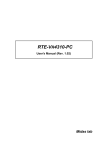
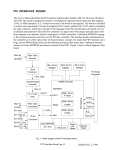
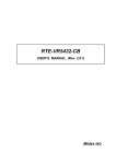
The overview of each function block of the RTE-V832-PC is shown below.
USER
HW
JEXT
CONNECTOR
SD-RAM
S-RAM
ROM
5 V <> 3.3 V
V832
Local Bus
PCI BUS I/F
Audio
SIO/PRT
RS-232C
CONNECTOR
PCI Bus
PARALLEL
CONNECTOR
TIMER
FPGA,..
CPU
CONNECTOR
Internal
Control
Mini jack *3
RTE-V832-PC Block Diagram
1
RTE-V832-PC
USER’S MANUAL (Rev. 1.03)
3.
MAJOR FEATURES
• Two types of monitor ROM are provided: one is used for the Green Hills Multi and the other for the
Midas PARTNER.
• Real-time execution and evaluation at a high-level language level using Multi or PARTNER.
• A ROM emulator can be connected.
• 512K bytes of high-speed SRAM and 32M bytes of SDRAM are provided as standard.
• SRAM and DRAM can be evaluated in 16-bit bus mode.
• Two serial interfaces and one printer interface are provided.
• Two timer channels are provided. (One channel is used for the monitor.)
• Two audio input channels and two audio output channels are provided.
4.
BASIC SPECIFICATIONS
Processor
CPU clock
Bus clock
Power consumption
Memory
EPROM
SRAM
DRAM
I/O
Serial (2 ch)
Printer
Audio input/output (2 ch)
Timer
I/O port
Others
CPU connector
32-bit standard external
extension bus
Reset switch
V832
142.8 MHz
47.6 MHz
+5 V (2 A)
128 KB
512 KB
32 MB
64 K × 16 bits (40-pin DIP) × 1 (512K bytes max.)
128 K × 8 bits × 4
64 M-SDRAM × 4
Equivalent to NS16550, 10-pin header, DB9 connector
IEEE1284-compatible, 26-pin header
µPD63310, Mini-jack (MIC × 2, LINEOUT × 1)
Equivalent to i8254, 500-ns resolution
LED (7-segment) display/switch input
Connector with all function pins of the V832 connected
RTE-PC standard 32-bit interface
(16M bytes, 32-bit bus, correspond to DMA)
Push type
2
RTE-V832-PC
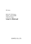
BOARD CONFIGURATION
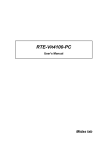
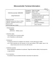
The physical layout of the major components on the RTE-V832-PC board is shown below. This chapter
explains each component.
1
99
2
1
2
100
JEXT
JPOWER
LED
26
25
JROM_EM
JPRT
2
10
1 JSIO2 9
RESETNMIGND
5.
USER’S MANUAL (Rev. 1.03)
LED_xxx
SW4
71054
JIN-L
B2
B1
A2
A1
27C1024
U24 - U27
SW_RESET
JOUT
ROM
79
1
80
SW3
TL16PIR552
SW1 JDCU SW2
JCPU1
2
JP6
PLD01
JP3 JP5 JP4
V832
JP1
JIN-R
JP2
PLD03
PLD02
PLD04
PCI9080
JSIO1
82
JCPU2
160
1
OSC5
OSC1
JISP
81
159
RTE-V832-PC Components Layout
5.1.
RESET SWITCH (RESET)
RESET is a reset switch for the entire board. Pressing this switch causes all the circuits including the
CPU to be reset.
5.2.
POWER JACK (JPOWER)
When this board is to be used as a standalone, that is, without being inserted in a PCI bus slot, the
board should be supplied with power from an external power supply by connecting it to the JPOWER
connector.
The external power should be one rated as listed below.
Voltage:
5V
Current:
Maximum of 2.0 A (excluding the current supplied to the JEXT connector)
Mating connector: Type A (5.5 mm in diameter)
Polarity:
+5V
GND
GND
+5V
[Caution] When attaching an external power supply to the board, be careful about its connector
polarity. When inserting the board into the PCI bus slot, do not attach the JPOWER connector to an
external power supply. It may result in a malfunction.
5.3.
SWITCH 1 (SW1)
SW1 is a general-purpose input port switch. When the monitor is used, all SW1 switches except some
are already set. When the port is read, a switch being set to OFF represents 1, while its being set to ON
represents 0. Set this switch for assignment with the monitor by referring to the following sections and in
accordance with your environment:
When using Multi, see Section 13.1.2.
When using PARTNER, see Section 14.1.1.
3
RTE-V832-PC
5.4.
USER’S MANUAL (Rev. 1.03)
SWITCH 2 (SW2)
SW2 sets the H/W status of this board. All the bits of this switch can be read by software. When this
switch is read from a port, OFF indicates 1 and ON indicates 0. For details, see Section 8.2.
No.
Function name
Description
1
BSIZE16
Specifies bus size of SRAM and SDRAM.
OFF: 32 bits (factory setting)
ON: 16 bits
2
BCLK_HI
Specifies frequency of bus clock.
OFF: Frequency exceeding 33 MHz (factory setting)
ON: Frequency less than 33 MHz
3
CMODE
Directly connected to CMODE pin of CPU.
OFF: Multiplied by 8
ON: Multiplied by 6 (factory setting)
4
TEST
5
ROM_TYPE0
6
ROM_TYPE1
Must always be OFF.
Specifies the type of ROM to be used.
[ROM_TYPE1, ROM_TYPE0]
[OFF, OFF] When monitor ROM is used (factory setting)
[OFF, ON] When 27C4096 is used
[ON, OFF] When 27C2048 is used
[ON, ON] When 27C1024 is used
5.5.
7
BNK_DIS
8
BNK_LOW
Specifies whether the upper and lower halves (banks) of ROM are separated
OFF: Upper and lower halves of ROM are separated (factory setting).
ON: Upper and lower halves of ROM are used as a contiguous area.
Selects either the upper or lower half when BNK_DIS = OFF
OFF: Selects upper half.
ON: Selects lower half (factory setting).
SWITCH 3 (SW3)
SW3 physically cuts the interrupts used in this board. All the bits of this switch are set to ON
(connected status) at the factory. Set the corresponding bit of this switch only when it is used
externally, and only when the internally used interrupt is unnecessary.
No.
INT name
Internally used interrupt source
1
INTP03
PIC-INT0 (Do not set this bit to OFF when the monitor is used.)
2
INTP02
PIC-INT1
3
INTP01
EXTbus-INT0
4
INTP00
Audio
5
INTP13
EXTbus-INT3
6
INTP12
EXTbus-INT2
7
INTP11
EXTbus-INT1
8
INTP10
Printer
4
RTE-V832-PC
5.6.
USER’S MANUAL (Rev. 1.03)
SWITCH 4 (SW4)
SW4 physically cuts the DMA used by this board. All the bits of this switch are set to ON
(connected status) at the factory. Set the corresponding bit of this switch only when it is used
externally, and only when the internally used DMA is unnecessary.
No.
DMA name
Internally used interrupt source
1
DMARQ2-
EXTbus-DREQ0-
2
DMAAK2-
EXTbus-DACK0-
3
DMARQ3-
EXTbus-DREQ1-
4
DMAAK3-
EXTbus-DACK1-
[Caution] Set switch bits 1 and 2, and 3 and 4 to the same positions.
5.7.
LED
The LEDs are used to indicate statuses, as listed below.
LED
Description
POWER
Lights when power is supplied to the RTE-V832-PC board.
PLY
Lights in green when voice is output.
Lights in red if an error occurs during voice output.
REC
Lights in green when voice is recorded.
Lights in red if an error occurs during voice recording.
PCI_PERR
Lights if a parity error occurs in the PCI bus.
PCI9_DEAD
Lights if the PCI controller is deadlocked.
TOVER
Lights when a time-out occurs.
LED Indication
[Caution] If PCI_PERR and PCI9_DEAD light, restart the system.
5.8.
TEST PINS FOR ROM EMULATOR (JROM_EM)
Test pins (JROM_EMs) are used to connect a ROM emulator. They accept control signals from the
ROM emulator. The following table lists the signal names and functions related to each test pin.
Signal
Input/
output
RESET(1)
Input
NMI(2)
Input
Function
When a low level is supplied to this test pin, the CPU is reset.
A reset request signal from the ROM emulator is connected to the test pin.
The test pin is pulled up with 1 kΩ .
When a low level is supplied to this test pin, an NMI signal is given to the CPU. This
signal can be masked by software, so it is necessary to reset the mask. (See Section
8.9.)
An NMI request signal from the ROM emulator is connected to the test pin.
The test pin is pulled up with 1 kΩ .
GND
(3)
---
This test pin is at a ground level. The ground level of the ROM emulator is connected
to the test pin.
JROM_EM Pin Functions
5
RTE-V832-PC
5.9.
USER’S MANUAL (Rev. 1.03)
CLOCK SOCKET (OSC1)
An oscillator for generating the clock signal to be supplied to the CPU is mounted in the OSC1 socket.
With the V832, a PLL is used to generate a system clock. The frequency of the oscillator must be onesixth or one-eighth the internal operating frequency of the V832.
Accepts DIP 8-pin (half-type) oscillators.
[Caution] When you have to cut an oscillator pin for convenience, be careful not to cut it too short, or
otherwise the frame (housing) of the oscillator may touch a tine in the socket, resulting in a short-circuit
occurring.
5.10. ROM SOCKETS
The RTE-V832-PC has ROM sockets to hold 40-pin ROM chips to provide standard 128K bytes (64K ×
16 bits). When the ROM chips used here are to be replaced, their type should be 27C1024, 27C2048,
or 27C4096, and the access time should be 120 ns or less. SW2 may need to be set according to the
type and purpose of the ROM chips to be used. For details, see Section 5.4.
5.11. DMARQ0-, DMARQ1- SEPARATION JUMPER (JP1)
JP1 is a jumper that physically cuts off DMARQ0- and DMARQ1-, used for Audio data transfer,
from the V832. Usually, jumper 1-2 , and 3-4.
[Remark] If this jumper is opened, Audio data cannot be transferred by means of DMA.
5.12. TIMER CLOCK FREQUENCY SELECT JUMPER (JP2)
JP2 is used to select which of two clocks is to be supplied to the timers (CH#1, CH#2) that can be used
by applications.
1-2 :
2 MHz (factory-set)
3-4:
4 MHz
5-6:
8 MHz
5.13. AUDIO INPUT LEVEL SELECT JUMPERS (JP3, JP4, JP5, JP6)
These jumpers are used to select the input level of Audio. Set these jumpers as shown below,
depending on whether MIC or LINE is used. MIC is the factory setting.
Input level
JP3
JP4
JP5
JP6
MIC
Short
1-2 short
1-2 short
Short
LINE
Open
2-3 short
2-3 short
Open
6
RTE-V832-PC
USER’S MANUAL (Rev. 1.03)
5.14. SERIAL CONNECTOR (JSIO1, JSIO2)
The JSIO1 and JSIO2 connectors are used for the RS-232C interface that is controlled by the serial
controller (TL16PIR552PH). JSIO1 is a 9-pin D-SUB RS-232C connector like that commonly used on
the PC/AT, while JSIO2 is a pin plug type connector with a pitch of 2.54 mm. All signals on both of
these connectors are converted to the RS-232C level. The figures and table below indicate the pin and
signal arrangements of these connectors.
For the signals to be connected to the host, the table indicates two modes of wiring on the host: one for
a 9-pin D-SUB connector, and the other for a 25-pin D-SUB connector. (Regular cross-cable wiring is
used for these connections.)
The pin arrangement of JSIO2 will be identical to that of JSIO1 when a push-fit connector is used with a
ribbon cable.
1
2
6
3
7
4
8
5
9
JSIO1 Pin Arrangement (Male)
2
4
6
8
10
1
3
5
7
9
JSIO2 Pin Arrangement
JSIO1
pin No.
JSIO2
pin No.
1
1
DCD
2
3
RxD(RD)
3
5
TxD(SD)
4
7
DTR(DR)
Output
5
9
GND
6
2
DSR(ER)
7
4
8
6
9
--
Signal name
Input/
output
Connector pin number on the host side
D-SUB9
D-SUB25
Input
3
2
Output
2
3
1, 6
6, 8
Input
5
7
Input
4
20
RTS(RS)
Output
8
5
CTS(CS)
Input
7
4
8
RI
Input
10
NC
JSIO1 and JSIO2 Connector Signals
7
RTE-V832-PC
USER’S MANUAL (Rev. 1.03)
5.15. PARALLEL CONNECTOR (JPRT)
The JPRT connector is used for parallel communication controlled by the parallel (printer) controller
(TL16PIR552PH). JPRT is a pin plug type connector with a 2.54 mm pitch. All signals on the connector
are 5-V level signals. The figure and table below indicate the pin and signal arrangements of the
connector.
The pin arrangement of JPRT will be identical to that of the 25-pin D-SUB connector, like that commonly
used on the PC/AT, when a push-fit connector is used with a ribbon cable.
2
4
6
8
10
12
14
16
18
20
22
24
26
1
3
5
7
9
11
13
15
17
19
21
23
25
JPRT Pin Arrangement
JPRT pin No.
Signal name
JPRT pin No.
Signal name
1
STB-
2
AUTO_FD-
3
D0
4
ERROR-
5
D1
6
INIT-
7
D2
8
SELECT_IN-
9
D3
10
GND
11
D4
12
GND
13
D5
14
GND
15
D6
16
GND
17
D7
18
GND
19
ACK-
20
GND
21
BUSY
22
GND
23
PE
24
GND
25
SELECT
26
NC
JPRT Connector Signals
5.16. AUDIO MINI-JACKS (JIN-R, JIN-L, JLINEOUT)
Audio jacks are provided for two monaural microphone or line input channels and one stereo output
channel. The input/output conditions of these jacks are indicated below.
JIN-R, JIN-L
Electrical input condition
When MIC input is specified: 140 mVp-p (Internal amplification: About 20 dB)
When LINE input is specified:
1.4 Vp-p
Physical shape of mating plug
Monaural mini-plug (φ3.5) × 2 channels
JLINEOUT
Electrical output condition
1.4 Vp-p
Physical shape of mating plug
Stereo mini-plug (φ3.5) × 1 channel
[Supplement] Selection between MIC and LINE is performed by setting JP3, JP4, JP5, and JP6.
8
RTE-V832-PC
USER’S MANUAL (Rev. 1.03)
5.17. DEBUGGING CONNECTOR (JDCU)
The JDCU connector is used to connect a debug tool based on the debug function built into the V832.
On-board connector: 8830E-026-170S manufactured by KEL
Pin No.
Signal name
Pin No.
Signal name
A1
TRCCLK
B1
GND
A2
TRCDATA0
B2
GND
A3
TRCDATA1
B3
GND
A4
TRCDATA2
B4
GND
A5
TRCDATA3
B5
GND
A6
NC.
B6
GND
A7
DDI
B7
GND
A8
DCK
B8
GND
A9
DMS
B9
GND
A10
DDO
B10
GND
A11
DRST-
B11
NC.
A12
NC.
B12
NC.
A13
NC.
B13
+3.3 V
JDCU Connector Signals
9
RTE-V832-PC
USER’S MANUAL (Rev. 1.03)
5.18. CPU CONNECTOR (JCPU-1, JCPU-2)
The CPU connector signals are connected directly to the V832. Many signals are used on the board.
So, be careful when extracting signals from the JCPU. The 3.3-V signal level is used.
Pin No.
Signal name
Pin No.
Signal name
1
GND
2
CS1-
3
CS0-
4
WE-
5
RAS-
6
UUDQM
7
ULDQM
8
LUDQM
9
LLDQM
10
+3.3 V
11
GND
12
SDCLKOUT
13
CKE
14
CAS-
15
A1
16
A2
17
A3
18
A4
19
+2.5 V
20
GND
21
+3.3 V
22
GND
23
A5
24
A6
25
A7
26
A8
27
A9
28
A10
29
A11
30
+3.3 V
31
GND
32
A12
33
A13
34
A14
35
A15
36
A16
37
A17
38
A18
39
A19
40
+5 V
41
GND
42
A20
43
A21
44
A22
45
A23
46
CLKOUT
47
BCLK2 (buffered CLKOUT)
48
MWR0-
49
MWR1-
50
MWR2-
51
MWR3-
52
NC.
53
NC.
54
NC.
55
NC.
56
NC.
57
NC.
58
GND
59
+2.5 V
60
GND
61
NC.
62
BT16B (GND)
63
RESET-
64
NMI-
65
NC.
66
CMODE
67
P3
68
P4
69
P2
70
P1
71
P0
72
+5 V
73
GND
74
INTP0
75
INTP12
76
INTP11
77
INTP13
78
PB0
79
PB1
80
+2.5 V
JCPU-1 Connector Signals
10
RTE-V832-PC
USER’S MANUAL (Rev. 1.03)
Pin No.
Signal name
Pin No.
Signal name
81
GND
82
INTP00
83
INTP01
84
INTP02
85
INTP03
86
DMARQ3-
87
DMARQ2-
88
DMARQ1-
89
DMARQ0-
90
DMAAK3-
91
DMAAK2-
92
DMAAK1-
93
DMAAK0-
94
TC-/STOPAK-
95
CS7-
96
CS6-
97
CS5-
98
CS4-
99
CS3-
100
CS2-
101
+3.3 V
102
GND
103
HLDAK-
104
HLDRQ-
105
R/W-
106
READY -
107
BCYST-
108
IORD-
109
IOWR-
110
UUBEN-
111
ULBEN-
112
LUBEN-
113
LLBEN-
114
MWR-
115
MRD-
116
+3.3 V
117
GND
118
D0
119
D1
120
+2.5 V
121
GND
122
D2
123
D3
124
D4
125
D5
126
D6
127
D7
128
+5 V
129
GND
130
D8
131
D9
132
D10
133
D11
134
D12
135
D13
136
D14
137
D15
138
+5 V
139
GND
140
D16
141
D17
142
D18
143
D19
144
D20
145
D21
146
D22
147
D23
148
+5 V
149
GND
150
+2.5 V
151
GND
152
D24
153
D25
154
D26
155
D27
156
D28
157
D29
158
D30
159
D31
160
+5 V
JCPU-2 Connector Signals
The connector used is the FX2-80P-1.27SV, manufactured by Hirose Electric Co., Ltd.
5.19. EXTENSION BUS CONNECTOR (JEXT)
The JEXT connector is provided to enable memory or I/O extension. This connector is internally
connected to the local bus of the board. For details, see Chapter 10.
11
RTE-V832-PC
6.
6.1.
USER’S MANUAL (Rev. 1.03)
CONNECTION WITH THE HOST PC
STANDALONE USE OF THE BOARD (RS-232C CONNECTION)
Serially connect the host machine by means of the following procedure:
<1>
Get an RS-232C cable for connection with the host and an external power supply (+5 V, ?? A) on
hand. For the power supply, watch for its voltage, capacity, and connector polarity. The RS232C cable is of the type generally called a cross cable. Confirm the wiring before using this
cable. See Sections 5.14. and 5.2. for RS-232C cable connection and the power supply,
respectively.
<2>
Set and check the setting of DIPSW on the board. Specify a baud rate by using SW1 (see
Sections 13.1.2 and 14.1.1).
<3>
Connect the JSIO1 connector and host machine with the RS-232C cable, and supply power to
the JPOWER connector. Confirm that the POWER-LED on the board lights. If the LED does
not light, turn off the power immediately, and check the connection.
<4>
Start the debugger on the host machine, and connect it via the RS-232C interface. If an error
occurs, confirm the setting of the serial cable and switches (especially, the baud rate).
[Cautions]
1. When power is applied to the board while the board is not connected to the PCI bus, also connect
the supplied PCI bus terminator board.
2. Place the board on an insulating material. If a conductive material touches the board while power
is supplied to the board, the board may malfunction.
6.2.
INSERTING INTO PCI SLOT (PCI BUS CONNECTION )
Insert the board into the PCI slot of the host PC by means of the following procedure:
<1>
Set and check the DIPSW on the board.
<2>
Open the housing of the PC, and insert the board into the PCI slot. Confirm that the board is
securely mounted, and fix the back panel with a screw.
<3>
Turn on the power to the PC, and check that the POWER-LED on the board lights. If the LED
does not light, turn off the PC power immediately, and check the connection. Also confirm
that the host machine operates normally.
<4>
Start the debugger on the host machine and connect it via the PCI bus. If an error occurs, check
whether the board is correctly mounted, and whether the software has been correctly installed.
12
RTE-V832-PC
7.1.
HARDWARE REFERENCES
This chapter describes the hardware of the RTE-V832-PC.
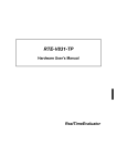
MEMORY AND I/O MAP
The figure below shows the memory and I/O mapping on the board.
0000-0000
Internal data RAM
CS7 space
CS6 space
4000-0000
Cacheable area
8000-0000
Uncacheable ICE reserve
area
area
Cacheable area
Cacheable area
EPROM
EPROM: mem area
4F80-0000 - 4FFF-FFFF
FF80-0000 - FFFF-FFFF
SRAM
SRAM: mem area
4E00-0000 - 4E07-FFFF
FE00-0000 - FE07-FFFF
SYSTEM-I/O
CS5 space
C000-0000
Built-in instruction RAM
7.
USER’S MANUAL (Rev. 1.03)
SYTEM IO,EXT-IO.. : IO area
4500-0000 - 45FF-FFFF
AUDIO
EXT-IO
CS4 space
EXF-Mem,…. : mem area
4400-0000 - 44FF-FFFF
EXT- Mem
Free area
CS3 space
CS2 space
CS1 space
PCI area....: mem area
4200-0000 - 427F-FFFF
PCI
SDRAM
DRAM : mem area
0000-0000 - 01FF-FFFF
4000-0000 - 41FF-FFFF
CS0 space
SDRAM
Memory and I/O Mapping
13
RTE-V832-PC
USER’S MANUAL (Rev. 1.03)
CS0 space (x000-000 to x0FF-FFFF, x800-000 to x8FF-FFFF)
SDRAM of 16M bytes is mapped. Both the 16-bit and 32-bit data bus widths can be specified by using
SW2-1. However, the memory capacity is limited to 8M bytes when the 16-bit width is selected.
For interfacing with SDRAM, the DRAM controller built into the V832 is used.
CS1 space (x100-000 to x1FF-FFFF, x900-000 to x9FF-FFFF)
SDRAM of 16M bytes is mapped. Both the 16-bit and 32-bit data bus widths can be specified by using
SW2-1. However, the memory capacity is limited to 8M bytes when the 16-bit width is selected.
For interfacing with SDRAM, the DRAM controller built into the V832 is used.
CS2 space (x200-000 to x27F-FFFF, xA00-000 to xA7F-FFFF)
A controller is mapped as a bridge to PCI.
CS3 space (x300-000 to x3FF-FFFF, xB00-000 to xBFF-FFFF)
CS3 is not used.
CS4 space (x400-000 to x40F-FFFF, xC00-000 to xC0F-FFFF)
The 16M-byte memory area on the EXT bus is mapped.
CS5 space (x500-000 to x5FF-FFFF, xD00-000 to xDFF-FFFF)
The I/O devices of the board, such as the timer, Audio, and serial and parallel interfaces, and EXT bus
IO area are mapped. Because full decoding is not performed, image spaces appear at various locations.
So, never attempt to access other than the specified I/O addresses.
Wait control is exercised by external FPGA. For details of each I/O device, see Chapter 8.
CS6 space (x600-000 to x6FF-FFFF, xE00-000 to xEFF-FFFF)
A high-speed SRAM of 512K bytes (NEC's µPD431008LE-15: 128K × 8 bits, 15 ns) is mapped. Both the
16-bit and 32-bit data bus widths can be specified by using SW2-1. A memory capacity of 512K bytes is
allocated even when the 16-bit width is selected. An SRAM image appears at 512K-byte intervals.
Wait control is exercised by the bus controller built into the CPU. Access is possible with no wait clock
cycles when a 33-MHz or less external clock is used.
CS7 space (x700-000 to x7FF-FFFF, xF00-000 to xFFF-FFFF)
This is a space for boot ROM that is booted by the 16-bit bus (BT16B pin is fixed to 16 bits).
As an EPROM, a 27C1024, 27C2048, or 27C4096 (120 ns or less) (40-pin DIP type) can be used. The
evaluation board is factory-fitted with a 27C1024 incorporating the monitor.
Wait control is exercised by the bus controller built into the CPU. The ROM area requires an access time
of 120 ns or longer.
[Caution] When SDRAM and SRAM are used at the 16-bit width, set SW2-1: BSIZE32 to ON and then
set the memory controller. Only either one of SDRAM and SRAM can be used at the 16-bit width.
14
RTE-V832-PC
8.
8.1.
USER’S MANUAL (Rev. 1.03)
I/O MAP
I/O devices such as Audio, UART/PRINTER, TIC, and PIO, and EXT-BUS are mapped to separate I/O
spaces. Thes e I/O spaces are mapped to the space of CS5. This section explains the mapping and I/O
devices.
I/O LIST
The table below lists the I/O areas and functions.
Address
Function
4500-0000H
See the description of DIPSW2.
4500-1000H
See the description of DIPSW1.
4500-2000H
7-segment LED display data setting
4500-5000H
Command setting/reference (Time-Over-Enable)
4500-6000H
EXT-BUS-High Addr setting/reference (EXA23, EXA22)
4500-8000H to 4500-801FH
UART-CH#1 (TL16PIR552) setting/reference
4500-9000H to 4500-901FH
UART-CH#2 (TL16PIR552) setting/reference
4500-A000H to 4500-A01FH
PRINTER-PP (TL16PIR552) setting/reference
4500-B000H to 4500-B00FH
Timer controller (µPD71054) setting/reference
4500-D000H to 4500-D01FH
Interrupt controller setting/reference
4500-E000H to 4500-E01FH
PRINTER-ECP (TL16PIR552) setting/reference
4540-0000H to 457F-FFFFH
EXT-BUS IO space (*1)
4580-0000H to 4580-001FH
Audio-Control register setting/reference
4580-1000H to 4580-100FH
µPD63310 register setting/reference
4580-2000H
Audio-FIFO data register setting/reference
*1: EXT-BUS I/O space
As the EXT-BUS I/O space, a 16M-byte space is accessed by using the EXT-IO high-order address
setting register (4500 through 6000H) to specify the high-order address. The relation between the
address and the I/O space that can be accessed is shown below.
Set value of EXT-IO high-order
address setting register [A23, A22]
I/O space of EXT-BUS that can be accessed by
4540-0000H through 457F-FFFFH
[0.0]
00-0000H to 3F-FFFFH
[0.1]
40-0000H to 7F-FFFFH
[1.0]
80-0000H to BF-FFFFH
[1.1]
C0-0000H to FF-FFFFH
15
RTE-V832-PC
8.2.
USER’S MANUAL (Rev. 1.03)
DIPSW2 READ PORT (4500-0000H [READ ONLY])
This port is used to read the status of DIP-SW2. The data format of this port is shown in the table below.
Data bus
Logical address
Setting
D7
D6
D5
D4
D3
D2
D1
D0
SW2
-8
SW2
-7
SW2
-6
SW2
-5
SW2
-4
SW2
-3
SW2
-2
SW2
-1
Hardware allocation BNK_
BNK_
ROM_
ROM_
PT_
MODE MODE
0
1
TYPE
1
TYPE
0
PRT
EN
4500-0000H
input
0 = ON
1 = OFF
CPU_ BCLK BSIZE
CMODE _Hi
32
SW2-1 corresponds to bit 1 of SW2, and SW2-8 corresponds to bit 8 of SW2. When a bit of the
corresponding switch is set to ON, 0 is read; when it is set to OFF, 1 is read. SW2 is mainly used to set
the hardware environment. For how to set this switch, see Section 5.4.
8.3.
DIPSW1 READ PORT (4500-1000H [READ ONLY])
This port is used to read the status of DIP-SW1. The table below indicates the data format.
Logical address
4500-1000H
input
Data bus
D7
D6
D5
D4
D3
D2
D1
D0
SW1
-8
SW1
-7
SW1
-6
SW1
-5
SW1
-4
SW1
-3
SW1
-2
SW1
-1
Setting
0 = ON
1 = OFF
SW1-1 corresponds to switch 1 of SW1, while SW1-8 corresponds to switch 8 of SW1. When a bit is
ON, 0 is read. When a bit is OFF, 1 is read. SW1 is used to set the operation of th e monitor. For how
to set this switch, see Sections 13.2.1 and 14.1.1.
8.4.
7-SEGMENT LED DISPLAY DATA OUTPUT PORT (4500-2000H [WRITE ONLY])
This port sets the data to be displayed on the 7-segment LED. The table below indicates the data
format. When a bit is set to 0, the corresponding segment is turned on.
Logical address
4500-2000H
output
Data bus
D7
D6
D5
D4
D3
D2
D1
7SEG
-DP
7SEG
-G
7SEG
-F
7SEG
-E
7SEG
-D
7SEG
-C
7SEG
-B
D0
Setting
7SEG 0 = Turned on
-A
1 = Turned off
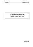
The figure below illustrates the correspondence between the bits and the segments of the
7-segment LED.
A
F
B
G
E
C
D
DP
16
RTE-V832-PC
8.5.
USER’S MANUAL (Rev. 1.03)
COMMAND REGISTER (4500-5000H [READ/WRITE])
This register has the following functions:
Logical address
Register
4500-5000H
CMD#1
(initial value)
Data bus
D7
D6
D5
D4
D3
D2
D1
D0
X
X
X
X
X
X
X
TOVEN
(0)
TOVEN: Controls the use of the time-over function. When the length of a bus cycle reaches 512 bus
clocks, the time-over function returns READY-, and forcibly terminates the bus cycle.
TOVEN
8.6.
Time-over function
0
Used
1
Not used
(Reset value)
EXT-IO HIGH-ORDER ADDRESS SETTING REGISTER (4500-6000H [READ/WRITE])
This register specifies a high-order address (A23, A22) to access the I/O space of the external extension
bus (EXT bus).
Logical address
4500-6000H
Register
CMD#1
(initial value)
Data bus
D7
D6
D5
D4
D3
D2
D1
D0
X
X
X
X
X
X
EA23
(0)
EA22
(0)
17
RTE-V832-PC
8.7.
USER’S MANUAL (Rev. 1.03)
UART/PRINTER (TL16PIR552) (4500-8000H TO 4500-A03EH)
The Texas Instruments TL16PIR552 (dual UART with 1,284 parallel port) LSI is used as
UART/PRINTER. TL16PIR552 has two UART channels and one bidirectional printer port channel
conforming to IEEE1284. It also has a 16-character FIFO buffer in the transmission/reception block of
the UART, and a function for automatically controlling RTS/CTS flow. Therefore, an overrun error can
be suppressed by the minimum interrupt.
Each register of the TL16PIR552 is assigned as listed below. For an explanation of the function of each
register, refer to the manual provided with the TL16PIR552. (The manual for TL16PIR552 is available
from the TI&ME corner of the Texas Instruments home page (http://www.ti.com/).)
Address
Function
Read
Write
4500-8000H
4500-8004H
4500-8008H
UART-CH#0
RBR/DLL
IER/DLM
IIR
THR/DLL
IER/DLM
FCR
4500-800CH
LCR
LCR
4500-8010H
4500-8014H
MCR
LSR
MCR
LSR
4500-8018H
MSR
MSR
4500-801CH
4500-9000H
SCR
RBR/DLL
SCR
THR/DLL
4500-9004H
4500-9008H
IER/DLM
IIR
IER/DLM
FCR
4500-900CH
LCR
LCR
4500-9010H
4500-9014H
MCR
LSR
MCR
LSR
4500-9018H
MSR
MSR
4500-901CH
4500-A000H
SCR
DATA
SCR
DATA/ECPAFIFO
4500-A004H
4500-A008H
DSR
DCR
----DCR
4500-A00CH
EPPADDR
EPPADDR
4500-A010H to 4500-A01CH
4500-E000H
EPPDATA
PPDATAFIFO/
TESTFIFO/CNFGA
EPPDATA
PPDATAFIFO/
TESTFIFO
CNFGB
ECR
----ECR
UART-CH#1
PRINTER (PPCS-)
PRINTER (ECPCS-)
4500-E004H
4500-E008H
TL16PIR552 Register Arrangement
The XIN input of the TL16PIR552 is connected to the 22.1184-MHz clock.
Each interrupt of UART-CH#0, UART-CH#1, and PRINTER can be connected to the interrupts of the
CPU via PIC. The interrupt from PRINTER can be directly connected to INTP10 of the V832 via SW3-8.
Interrupt source
PRINTER
Connected CPU interrupt
INTP10
Interrupt edge
Rising edge
UART-CH#0 is connected to the JSIO1 connector on the rear panel of the board, UART-CH#1 is
connected to the JSIO2 connector, and PRINTER is connected to JPRT. UART-CH#0 is used when the
debugger is used in serial communication mode. At this time, INTP3 or NMI is used as the interrupt via
PIC.
TL16PIR552 is reset when the s ystem is reset.
18
RTE-V832-PC
8.8.
USER’S MANUAL (Rev. 1.03)
TIC (µPD71054) (4500-B000H TO 4500-B00CH)
The NEC µPD71054 is installed as a TIC. The µPD71054 is compatible with the Intel i8254. It has three
timers/counters. These timers/counters are used to generate monitor timer interrupts.
Each register of the TIC is assigned as listed below.
Address
Read
Write
4500-B000H
COUNTER#0
COUNTER#0
4500-B004H
COUNTER#1
COUNTER#1
4500-B008H
COUNTER#2
COUNTER#2
4500-B00CH
-----
Control Word
TIC Register Arrangement
The channels of the TIC are connected as shown in the figure below.
Channel 0 is used as the interval timer for the monitor program.
Channels 1 and 2 can be used by a user program as necessary.
Channel 2 is connected to channel 1 by means of a cascade connection.
µPD71054
2 MHz
CLK
JP6
From JP2
CH#0
GATE
CLK
CH#1
GATE
CLK
GATE
CH#2
OUT
PIC (to interrupt controller)
OUT
PIC (to interrupt controller)
OUT
Examples of modes
CH#0: Mode 2 (rate generator)
CH#1: Mode 2 (rate generator)
CH#2: Mode 0 (down counter)
19
RTE-V832-PC
8.9.
USER’S MANUAL (Rev. 1.03)
INTERRUPT CONTROLLER (PIC) (4500-D000H TO 4500-D018H)
The PIC mainly exercises interrupt-related control. The table below indicates the assignment of
registers.
With the RTE-V832-PC, INT0 of the PIC is connected to NMI or INTP03 of the V832 according to the
specification of NMI/INT3-. INT1 is connected to INTP02.
Logical address
Data bus
Register
D7
D6
D5
D4
D3
D2
D1
D0
4500-D000H
PIC INT0M
0
IM06 IM05
IM04
IM03 IM02 IM01
IM00
4500-D008H
PIC INT1M
0
IM16 IM15
IM14
IM13 IM12 IM11
IM10
4500-D010H
PIC INTR
IR7
IR6
IR5
IR4
IR3
IR2
IR1
IR0
4500-D018H
PIC INTEN
0
0
0
NMI/
INT3-
0
0
0
NMIEN
The INT0M and INT1M registers mask interrupts applied to INT0 and INT1, respectively. When the
IM0x or IM1x bit is set to 1, the interrupt is enabled. When multiple bits are selected, each OR value
activates an interrupt.
[Caution] Always write 0 into bit 7 of INT0M and INT1M.
The INTR register is an interrupt status register, for which 1 is read whenever there is an interrupt
request. This does not depend on the state of masking. To clear an edge interrupt request, the
corresponding bit of this register must be set to 1.
The table below indicates the interrupt source assigned to each bit of IM0[0..7], IM1[0..7], and IR[0..7].
IM0, IM1, IR
Interrupt source
Request level
0
Timer 0 (mode 2)
Edge (rising)
1
Serial 0
Level (high)
2
Host (PCI communication)
Level (low)
3
Time-over
Edge (rising)
4
Timer 1 (mode 2)
Edge (rising)
5
Serial 1
Level (high)
6
Parallel (printer)
Edge (rising)
7
Reserved
Edge (falling)
The INTEN register enables or disables all interrupts.
NMIEN: Disables a non-maskable interrupt (NMI) by hardware. At this time, the NMI pin is high. The
NMI request from the JROM_EM1 connector is input to the CPU, regardless of this bit.
NMIEN
NMI
0
Sets a mask.
1
Does not set a mask.
(Reset value)
NMI/INTP3-: Specifies whether an INT0 interrupt is to be applied to NMI or INTP03.
NMI/INTP3-
INT0
0
INTP03
1
NMI
(Reset value)
[Caution] INT0 (NMI/INTP03) is used with the monitor. So, never modify the related registers. INT1 is
released, and can be used freely.
20
RTE-V832-PC
USER’S MANUAL (Rev. 1.03)
8.10. AUDIO CONTROLLER (AUDCNT) (4580-0000H TO 4580-0010H, 4580-2000H)
AUDCNT controls digital data input to and output from the audio chip (µPD63310).
Logical address
4580-0000H
4580-0008H
4580-0010H
4580-2000H
Register
CONTROL
STATUS
MCLKDIV
Data bus
D15
D14
D13
D12
D11
D10
D9
D8
RST
0
0
0
0
RM1
RM0
REC
D7
D6
D5
D4
D3
D2
D1
D0
0
0
0
0
0
PM1
PM0
PLY
D15
D14
D13
D12
D11
D10
D9
D8
0
FF1
0
EF1
0
ROV
RUD
REX
D7
D6
D5
D4
D3
D2
D1
D0
0
FF0
0
EF0
0
POV
PUD
PEX
D15
D14
D13
D12
D11
D10
D9
D8
0
0
0
0
0
0
0
0
D7
D6
D5
D4
D3
D2
D1
D0
0
0
0
DIV4
DIV3
DIV2
DIV1
DIV0
AUDIO DATA
D15
to D0
First time: L channel, 16 bits, Second time: R channel, 16 bits
The CONTROL register controls voice recording/replay. (Read/write)
RST
Audio reset
0
Reset clear
1
Reset
PLY
(Reset value)
Replay operation
0
Stop
1
Start
PM0
(Reset value)
Underflow interrupt upon replay
0
Disable
1
Enable
PM1
(Reset value)
Overflow interrupt upon replay
0
Disable
1
Enable
REC
(Reset value)
Recording operation
0
Stop
1
Start
RM0
(Reset value)
Underflow interrupt upon recording
0
Disable
1
Enable
RM1
(Reset value)
Overflow interrupt upon recording
0
Disable
1
Enable
(Reset value)
21
RTE-V832-PC
USER’S MANUAL (Rev. 1.03)
The STATUS register is a read-only register for indicating various statuses.
PEX
Replay status
0
Stopped
1
Being conducted
POV
Overflow upon replay
0
No overflow detected
1
Overflow detected
PUD
Underflow upon replay
0
No underflow detected
1
Underflow detected
FF0
EF0
Data buffer status for replay
0
1
Empty
1
0
Full (buffer write disabled)
REX
Recording status
0
Stopped
1
Being conducted
ROV
Overflow upon recording
0
No overflow detected
1
Overflow detected
RUD
Underflow upon recording
0
No underflow detected
1
Underflow detected
FF1
EF1
Data buffer status for recording
0
1
Empty (buffer read disabled)
1
0
Full
22
RTE-V832-PC
USER’S MANUAL (Rev. 1.03)
The MCLKDIV register is used to determine the MCLK frequency.
Sampling frequency
(MCLK/256)
Bytes/sec
fs * 4
12.288 MHz
48.0 KHz
192.0 KB
1
9.830 MHz
38.4 KHz
153.6 KB
0
8.192 MHz
32.0 KHz
128.0 KB
0
1
7.022 MHz
27.5 KHz
109.7 KB
1
0
6.144 MHz
24.0 KHz
96.0 KB
1
1
1
5.461 MHz
21.3 KHz
85.3 KB
1
0
0
0
4.915 MHz
19.2 KHz
76.8 KB
1
0
0
1
4.468 MHz
17.5 KHz
69.8 KB
0
1
0
1
0
4.096 MHz
16.0 KHz
64.0 KB
0
1
0
1
1
3.780 MHz
14.8 KHz
59.1 KB
0
1
1
0
0
3.511 MHz
13.7 KHz
54.9 KB
0
1
1
0
1
3.277 MHz
12.8 KHz
51.2 KB
0
1
1
1
0
3.072 MHz
12.0 KHz
48.0 KB
0
1
1
1
1
2.891 MHz
11.3 KHz
45.2 KB
1
0
0
0
0
2.731 MHz
10.7 KHz
42.7 KB
1
0
0
0
1
2.587 MHz
10.1 KHz
40.4 KB
1
0
0
1
0
2.458 MHz
9.6 KHz
38.4 KB
1
0
0
1
1
2.341 MHz
9.1 KHz
36.6 KB
1
0
1
0
0
2.234 MHz
8.7 KHz
34.9 KB
1
0
1
0
1
2.137 MHz
8.3 KHz
33.4 KB
1
0
1
1
0
2.048 MHz
8.0 KHz
32.0 KB
1
0
1
1
1
1.966 MHz
7.7 KHz
30.7 KB
1
1
0
0
0
1.890 MHz
7.4 KHz
29.5 KB
1
1
0
0
1
1.820 MHz
7.1 KHz
28.4 KB
1
1
0
1
0
1.755 MHz
6.9 KHz
27.4 KB
1
1
0
1
1
1.695 MHz
6.6 KHz
26.5 KB
1
1
1
0
0
1.638 MHz
6.4 KHz
25.6 KB
1
1
1
0
1
1.586 MHz
6.2 KHz
24.8 KB
1
1
1
1
0
1.536 MHz
6.0 KHz
24.0 KB
1
1
1
1
1
1.489 MHz
5.8 KHz
23.3 KB
DIV2 DIV1 DIV0
MCLK
49.152/(DIV + 2)
DIV4
DIV3
0
0
0
0
0
24.576 MHz
0
0
0
0
1
16.384 MHz
0
0
0
1
0
0
0
0
1
0
0
1
0
0
0
1
0
0
1
0
0
0
0
8.11. µPD63310 REGISTER (4580-1000H TO 4580-100FH)
The µPD63310 register is assigned as indicated below. For details, refer to the data sheet provided with
the µPD63310.
Address
Function
D5
D4
D3
D2
D1
4580-1000H
Address register
Register number
4580-1008H
Data register
Gain control data
D0
23
RTE-V832-PC
9.
9.1.
USER’S MANUAL (Rev. 1.03)
INTERRUPTS AND DMA
This chapter describes the interrupts and DMA for the RTE-V832-PC.
INTERRUPT
External interrupt
NMI-
Interrupt signal
Remark
NMI
INT0 (dedicated to MONITOR) interrupt signal of PIC
INTP00
INT_AUDIO
Interrupt can be generated when an error occurs.
INTP01
EXTBUS-INT0
Interrupt request from INT0 of EXT-BUS
INTP02
PIC-INT1
Interrupt request from INT1 (USER-released) of PIC
INTP03
PIC-INT0
Interrupt request (dedicated to MONITOR) from INT0 of PIC
INTP10
INT_PRN
Interrupt request from printer IF
INTP11
EXT-BUS INT1
Interrupt request from INT1 of EXT-BUS
INTP12
EXT-BUS INT2
Interrupt request from INT2 of EXT-BUS
INTP13
EXT-BUS INT3
Interrupt request from INT3 of EXT-BUS
Remarks 1. All the interrupts, except NMI, are positive logical request signals.
2. All the signals can be physically separated by using SW3 (they are connected in the factory
setting).
3. All the interrupts from EXT-BUS are inverted and connected to the V832.
4. Two interrupts (INT0, INT1) can be generated by selecting interrupt requests from the
interrupt sources listed below with the interrupt controller (see Section 8.9). INT0 is used for
the system (used with the monitor), while INT1 is used for a user application.
Interrupt sources selectable by PIC
Timer 0 (mode 2)
Serial CH#0
Host (PCI communication)
Time-over
Timer 1 (mode 2)
Serial CH#1
Parallel (printer)
9.2.
USING NMI
This section describes the method of using NMI for transporting the monitor, for example, to the board.
NMI is edge-detected. NMI can be masked by hardware because the interrupt source is a level output.
For an explanation of masking, see the description of the INTEN register in Section 8.9.
The following procedure applies when an NMI occurs.
<1>
Set the NMIEN of the PIC to 0 to mask the NMI by hardware.
<2>
Check the INTR of the PIC.
<3>
Perform NMI processing for the interrupt source, and clear the request.
<4>
Reset the NMIEN of the PIC to 1 to reset the mask.
<5>
Return from NMI processing.
[Caution] When data is written to a register related to INT0 of NMI, INTP03, and PIC, the monitor may
hang up.
24
RTE-V832-PC
9.3.
USER’S MANUAL (Rev. 1.03)
DMA REQUEST
DMARQ-/AK-
DMARQ signal
Remark
CH0
Replay request
A DMA request for data to be written to the audio data buffer
during replay. A timeout results in an underrun error.
CH1
Recording request
A DMA request for data to be read from the audio data buffer
during recording. A timeout results in an overflow error.
CH2
DMARQ0- request
from EXT-BUS
CH3
DMARQ1- request
from EXT-BUS
Remarks 1. Set DMARQ-/AK-[3..0] to negative logic.
2. CH0 and CH1, JP1, and CH2 and CH3 can be physically separated by using SW4 (they are
connected in the factory setting).
25
RTE-V832-PC
USER’S MANUAL (Rev. 1.03)
10. EXT-BUS
The JEXT connector is a connector for the EXT-BUS provided to extend the memory or I/O. The local bus
of this board is connected to the JEXT connector.
10.1. PIN ARRANGEMENT
Number
Signal name
Number
Signal name
Number
Signal name
Number
Signal name
1
GND
2
+5 V
5
D2
6
D3
3
D0
4
D1
7
GND
8
9
D5
10
D4
D6
11
D7
12
GND
13
D8
17
GND
14
D9
15
D10
16
D11
18
D12
19
D13
20
21
D14
D15
22
GND
23
D16
24
D17
25
D18
26
D19
27
GND
28
D20
29
D21
30
D22
31
D23
32
GND
33
D24
34
D25
35
D26
36
D27
37
GND
38
D28
39
D29
40
D30
41
D31
42
GND
43
+5 V
44
GND
45
Reserve
46
Reserve
47
(A1)
48
A2
49
A3
50
A4
51
GND
52
A5
53
A6
54
A7
55
A8
56
A9
57
A10
58
GND
59
A11
60
A12
61
A13
62
A14
63
A15
64
A16
65
GND
66
A17
67
A18
68
A19
69
A20
70
A21
71
A22
72
A23
73
GND
74
+5 V
75
MRD-
76
Reserve
77
MWR0-
78
MWR1-
79
NWR2-
80
MWR3-
81
IORD-
82
IOWR-
83
GND
84
READY
85
GND
86
INT0-
87
INT1-
88
INT2-
89
INT3-
90
DMARQ0-
91
DMARQ1-
92
DMAAK0-
93
DMAAK1-
94
RESET-
95
32/16BIT-
96
N/C
97
+5 V
98
GND
99
CLK
100
GND
JEXT Connector Pin Arrangement
2
1
100
Pin 1 mark
Board edge
99
JEXT Pin Arrangement
26
RTE-V832-PC
USER’S MANUAL (Rev. 1.03)
10.2. SIGNALS
Signal name
Input/output
Function
D[0..31]
Input/output
A[1..23]
MRD-
Output
Output
MWR-[0..3]
Output
IORD-
Output
IOWR-
Output
READY
Input
INT-[0..3]
Input
DMARQ-[0..1]
Input
DMAAK-[0..1]
Output
RESET32/16BIT-
Output
Input
CLK
Reserve
Output
--
Data bus signal, connected to the CPU data bus signal via a buffer
It is pulled up with a 10-kΩ resistor on the board.
Address bus signal, connected to the CPU address signal via a buffer
Memory read cycle timing signal, which becomes active only when the EXT-BUS
space is accessed.
Memory write cycle timing signal. MWR0- corresponds to D[0..7], MWR1-, to
D[8..15], MWR2-, to D[16..23], and MWR3-, to D[24..31]. This signal becomes
active only when the EXT-BUS space is accessed.
Timing signal of the I/O read cycle. Asserted active when the EXT-BUS space is
accessed or in the flyby DMA cycle (reference).
Timing signal of the I/O write cycle. Asserted active when the EXT-BUS space is
accessed or in the flyby DMA cycle (reference).
Signal for notifying the CPU of the end of a cycle. It is valid for the EXT-BUS space.
To have the CPU reliably recognize READY, it is necessary to keep READY active
until MRD-, MWR-[0..3], IORD-, or IOWR- becomes inactive. It is pulled up with a
10-kΩ resistor on the board.
Active-low interrupt request signal. Connected to the INTP01, INTP11, INTP12, and
INTP13 pins of the CPU, respectively, via SW3 after being buffered by the inverter.
It is pulled up by a 10 kΩ resistor on the board (see Chapter 9).
Active-low DMA request signals. Connected to the DMARQ2- and DMARQ3- pins of
the CPU via SW4 after being buffered. Pulled up by a 10 kΩ resistor on the board
(see Chapter 9).
Active-low DMA acknowledge signals. DMAAK0- and DMAAK1- of the CPU are
buffered and connected via SW4 (see Chapter 9).
Active-low system reset signal
When this signal goes low, only D[15..0] are used if the CPU is in the 16-bit data
bus mode. If the CPU is in the 32-bit data bus mode, D[15..0] or D[31..16] are used
as an address bus (16-bit bus mode).
When this signal goes high, D[31..0] of the data bus are used (32-bit bus mode).
This signal must not be changed dynamically. It is pulled up by a 10 kΩ resistor on
the board.
Clock signal, connected to the CLKOUT pin of the V832 after a buffer.
Reserved signal. Connect nothing to this pin when the board uses EXT-BUS.
JEXT Connector Signals
Cautions 1. The 32/16BIT- signal will not be supported by all the products of the RTE-PC series in
the future. If it is planned to use the board connected to EXT-BUS with a new member
of the RTE-PC series, design the board so that it operates in 32-bit bus mode.
When 32/16BIT- is low, MWR2- and MWR3- are not asserted. Instead, MWR0- and
MWR1- are asserted.
When 32/16BIT- is low, jumper D[15..0] and D[31..16] on the board connected to EXTBUS (see Section 10.3).
2. A1 is valid when the 32/16BIT- signal is low. Therefore, A1 will not be output by future
RTE-PC series that do not support the 32/16BIT- signal.
3. The maximum access bus width in one cycle of the EXT-BUS depends on the bus width
of the data bus of the CPU. This does not pose a problem to the V832 because it has a
32-bit data bus. If a 16-bit CPU is used, however, the data size that can be accessed at
any one time is limited to a maximum of 16 bits. This must be taken into consideration
when designing a general-purpose board that is to be used with this bus.
4. The DMA function will not be supported by all members of the RTE-PC series in the
future.
27
RTE-V832-PC
USER’S MANUAL (Rev. 1.03)
10.3. CONNECTION OF DATA BUS
10.3.1. 16-Bit Data Bus CPU (Reference)
Cycle : EXT-BUS Memory Space
Access Address : 4n+0 and/or 4n+1
32/16Bit - : High
RTE-PC
EXT-BUS
Cycle : EXT-BUS Memory Space
Access Address : 4n+2 and/or 4n+3
32/16Bit - : High
User Board
RTE-PC
D[31..16]
User Board
D[31..16]
CPU
D[15..0]
EXT-BUS
CPU
D[15..0]
D[15..0]
D[15..0]
Cycle : EXT-BUS I/O Space
Access Address : 4n+0 and/or 4n+1
32/16Bit - : High
RTE-PC
EXT-BUS
User Board
D[31..16]
CPU
D[15..0]
D[15..0]
Cycle : Flyby-DMA
32/16Bit - : High
RTE-PC
EXT-BUS
User Board
D[31..16]
CPU
D[15..0]
D[15..0]
Cycle : EXT-BUS Memory Space
Access Address : 4n+0 and/or 4n+1
32/16Bit - : Low
RTE-PC
EXT-BUS
Cycle : EXT-BUS Memory Space
Access Address : 4n+2 and/or 4n+3
32/16Bit - : Low
User Board
RTE-PC
D[31..16]
CPU
D[15..0]
D[15..0]
Cycle : EXT-BUS I/O Space
Access Address : 4n+0 and/or 4n+1
32/16Bit - : Low
RTE-PC
EXT-BUS
D[15..0]
Cycle : EXT-BUS I/O Space
Access Address : 4n+2 and/or 4n+3
32/16Bit - : Low
User Board
RTE-PC
D[31..16]
EXT-BUS
User Board
D[31..16]
CPU
D[15..0]
User Board
D[31..16]
CPU
D[15..0]
EXT-BUS
CPU
D[15..0]
D[15..0]
D[15..0]
Cycle : Flyby-DMA
32/16Bit - : Low
RTE-PC
EXT-BUS
User Board
D[31..16]
CPU
D[15..0]
D[15..0]
28
RTE-V832-PC
USER’S MANUAL (Rev. 1.03)
10.3.2. 32-Bit Data Bus CPU (with V832)
Cycle : EXT-BUS Memory Space
Access Address : 4n+0 and/or 4n+1 and/or 4n+2 and/or 4n+3
32/16Bit - : High
RTE-PC
CPU
D[31..16]
D[15..0]
EXT-BUS
User Board
D[31..16]
D[15..0]
Cycle : EXT-BUS I/O Space
Access Address : 4n+0 and/or 4n+1 and/or 4n+2 and/or 4n+3
32/16Bit - : High
RTE-PC
CPU
D[31..16]
D[15..0]
EXT-BUS
User Board
D[31..16]
D[15..0]
Cycle : Flyby-DMA (Reference)
32/16Bit - : High
RTE-PC
CPU
D[31..16]
D[15..0]
EXT-BUS
User Board
D[31..16]
D[15..0]
Cycle : EXT-BUS Memory Space
Cycle : EXT-BUS Memory Space
Access Address : 4n+0 and/or 4n+1
Access Address : 4n+2 and/or 4n+3
32/16Bit - : Low
32/16Bit - : Low
RTE-PC
CPU
D[31..16]
D[15..0]
EXT-BUS
User Board
D[31..16]
D[15..0]
RTE-PC
CPU
D[31..16]
D[15..0]
EXT-BUS
User Board
D[31..16]
D[15..0]
Cycle : EXT-BUS I/O Space
Cycle : EXT-BUS I/O Space
Access Address : 4n+0 and/or 4n+1
Access Address : 4n+2 and/or 4n+3
32/16Bit - : Low
32/16Bit - : Low
RTE-PC
CPU
D[31..16]
D[15..0]
EXT-BUS
User Board
D[31..16]
D[15..0]
RTE-PC
CPU
D[31..16]
D[15..0]
EXT-BUS
User Board
D[31..16]
D[15..0]
Cycle : Flyby-DMA (Reference)
Cycle : Flyby-DMA (Reference)
Access Memory Address : 4n+0 and/or 4n+1
Access Memory Address : 4n+2 and/or 4n+3
32/16Bit - : Low
32/16Bit - : Low
RTE-PC
CPU
D[31..16]
D[15..0]
EXT-BUS
User Board
D[31..16]
D[15..0]
RTE-PC
CPU
D[31..16]
D[15..0]
EXT-BUS
User Board
D[31..16]
D[15..0]
29
RTE-V832-PC
USER’S MANUAL (Rev. 1.03)
10.4. TIMING
A[1..23]
DMAAK-[0..1]
A[1..23]
DMAAK-[0..1]
T1
T3
T2
MRDIORDMWR-[0..3]
IOWR-
MRDIORD-
T4
High
T5
T6
MWR-[0..3]
IOWR-
Din
D[0..31]
T7
T8
High
T10
T12
T13
T14
READY
T15
Dout
D[0..31]
T9
T11
T16
T17
T18
READY
Read cycle
Write cycle
DMAAK-[0..1]
IORDIOWRT19
DMARQ-[0..1]
DMA cycle
EXT-BUS Cycle
Symbol
Description
Min. (ns)
T1
ADDR, DMAAK- → MRD-, IORD- setup time
10
T2
MRD-, IORD- → ADDR, DMAAK- hold time
10
T3
MRD-, IORD- cycle time
50
T4
MRD-, IORD- cycle interval
20
T5
RD DATA → RD READY setup time
0
T6
MRD-, IORD- → RD DATA hold time
0
T7
MRD-, IORD- → RD READY delay time
T8
RD READY → MRD-, IORD- delay time
15
T9
MRD-, IORD- → RD READY hold time
0
T10
ADDR, DMAAK- → MWR-, IOWR- setup time
10
T11
MWR-, IOWR- → ADDR, DMAAK- hold time
10
T12
MWR-, IOWR- cycle time
50
T13
MWR-, IOWR- cycle interval
20
T14
MWR-, IOWR- → WR DATA delay time
T15
MWR-, IOWR- → WR DATA hold time
T16
MWR-, IOWR- → WR READY delay time
T17
WR READY → MWR-, IOWR- delay time
0
T18
MWR-, IOWR-, → WR READY hold time
0
T19
IORD-, IOWR- → DMARQ- inactive delay time
Max. (ns)
20
20
10
20
xx
EXT-BUS AC Specifications
30
RTE-V832-PC
USER’S MANUAL (Rev. 1.03)
10.5. APPLICABLE CONNECTORS
The connectors used for EXT-BUS and the connectors that can be connected to those connectors are
listed below. If EXT-BUS is connected to multiple boards, use a cable to make a daisy-chain connection.
EXT-BUS connector
: KEL 8830E-100-170S
Applicable connector (for board) : KEL 8802-100-170S
Applicable connector (for cable)
: KEL 8825E-100-175
Right angle for cable (for board) : KEL 8830E-100-170L
KEL 8831E-100-170L
10.6. NOTES ON USE
The following points must be noted when designing the board that is to be connected to EXT -BUS.
1.
When two or more boards are connected to EXT-BUS, Hi-Z control must be performed so that the
READY signal is driven only when a board is selected.
2.
T7 and T16 must be satisfied to insert a wait state into the cycles of EXT-BUS. To do so, control
with the normal not ready technique (that retains the not ready status normally and returns ready
when an access takes place and the slave device is ready) is recommended.
3.
When executing a DMA cycle in single transfer mode, T19 in the timing chart must be satisfied if
the next DMA cycle is not to be generated. However, T19 differs among the products because it is
heavily dependent upon the specifications of the DMA controller.
4.
Because there is not an enough space to access the 16M-byte I/O space of EXT-BUS with RTEV832-PC, the high-order two bits (A23 and A22) are accessed by the outputs from the EXT-IO
high-order address setting register #1 port. For details of this port, see Section 8.6.
31
RTE-V832-PC
USER’S MANUAL (Rev. 1.03)
11. SOFTWARE
This chapter describes the initialization of the hardware of the RTE-V832-PC board, and explains how to
use peripheral devices.
11.1. INITIALIZATION
The boot routine initializes the bus controller built into the V832 for external memory or I/O access as
follows.
Bus clock: 33 MHz Max.
Register
Internal I/O address
Set value
Size
BCTC
DBC
Remarks
C000-0010H
22H
byte
C000-0012H
00H (43H)
byte
PWC0
C000-0014H
7000H
half-word
PWC1
C000-0016H
4000H
half-word
PIC0
C000-0100H
0000H
half-word
PIC1
C000-0102H
0000H
half-word
SDC
C000-0020H
9401H
half-word
RFC
C000-0022H
0102H
8102H
half-word
First time: 33MHz >> 11.5 µs
Second time: Refresh Enable
PAC
C000_00F4
FFH
byte
Port A: select DMACont sig.
PBC
C000_00FA
FFH
byte
Port B: select INTPxx
Set value
Size
( ) indicates the set value when
SW2-1 (BSIZE32) is ON(0).
Bus clock: 33 MHz Min.
Register
Internal I/O address
Remarks
BCTC
C000-0010H
22H
byte
DBC
C000-0012H
00H (43H)
byte
PWC0
C000-0014H
7200H
half-word
PWC1
C000-0016H
7111H
half-word
PIC0
C000-0100H
0000H
half-word
PIC1
C000-0102H
0000H
half-word
SDC
C000-0110H
941AH
half-word
RFC
C000-0022H
0104H
8104H
half-word
PAC
C000_00F4
FFH
byte
Port A: select DMACont sig.
PBC
C000_00FA
FFH
byte
Port B: select INTPxx
( ) indicates the set value when
SW2-1 (BSIZE32-) is ON(0).
First time:47.6MHz >> 13.4 µs
Second time: Refresh Enable
For detailed information about the registers, refer to the manual provided with the V832 CPU.
32
RTE-V832-PC
USER’S MANUAL (Rev. 1.03)
11.2. LIBRARIES
Libraries are required for programming using the C compiler for I/O accesses and other purposes.
However, the methods of writing these libraries and passing their parameters described below are
specific to the MULTI. So, modifications may be required, for example, when another compiler is used.
/* I/O library */
/* GHS V800 compiler parameter passing */
/* arg0 : r6, arg1 : r7, arg2 : r8, return : r10 */
inb(int addr)
{
__asm(“ in.b 0[r6], r10”);
}
/* Byte (8 bits) input */
inh(int addr)
{
__asm(“ in.h 0[r6], r10”);
}
/* Half -word (16 bits) input */
inw(int addr)
{
__asm(“ in.w 0[r6], r10”);
}
/* Word (32 bits) input */
outb(int addr, int data)
{
__asm(“ out.b r7, 0[r6]”);
}
/* Byte (8 bits) output */
outh(int addr, int data)
{
__asm(“ out.h r7, 0[r6]”);
}
/* Half -word (16 bits) output */
outw(int addr, int data)
{
__asm(“ out.w r7, 0[r6]”);
}
/* Word (32 bits) output */
33
RTE-V832-PC
USER’S MANUAL (Rev. 1.03)
11.3. USING TIMERS
A sample time measurement is indicated below which uses timer 1 and timer 2 cascaded with each
other by an external timer (8254) on the board. Timer 1 is initialized as an interval counter (mode 2),
and timer 2 is initialized as a down counter (mode 0). By determining the counter values before and
after a routine whose execution time is to be measured, the execution time can be calculated. Note that
both timers function as down counters. Note also that command recovery (dummy read from the ROM
area) is required for successive accesses to the external timer.
/* Sample execution time measurement using timers */
#define TIMERCLK
#define INTERVAL
#define IOWAIT()
/* 2MHz */
/* 10 ms (1/100) */
/* For I/O command recovery */
2000000
(TIMERCLK * 10 / 1000)
(*(char *)0x4FFF0000))
InitTimer()
{
outb(0x4500B00C,
outb(0x4500B004,
outb(0x4500B004,
outb(0x4500B00C,
outb(0x4500B008,
outb(0x4500B008,
return 0;
}
/* Timer initialization */
0x74);
INTERVAL);
INTERVAL / 256);
0xB0);
0xFF);
0xFF);
IOWAIT();
IOWAIT();
IOWAIT();
IOWAIT();
IOWAIT();
IOWAIT();
LatchTimer()
{
int count1, count2, counts;
outb(0x4500B00C, 0xDC);
IOWAIT();
count1 = inb(0x4500B004);
IOWAIT();
count1 += inb(0x4500B004) * 256;
IOWAIT();
count2 = inb(0x4500B008);
IOWAIT();
count2 += inb(0x4500B008) * 256;
IOWAIT();
counts = INTERVAL * (0xFFFF - count2)
+ (INTERVAL - count1);
return counts;
/*
/*
/*
/*
/*
/*
Timer 1 set to mode 2 */
Lower digit count of timer 1 */
Higher digit count of timer 1 */
Timer 2 set to mode 0 */
Lower digit count of timer 2 */
Higher digit count of timer 2 */
/* Count Latch */
/* Timer 1/2 multiple latch */
/* Count of timer 1 */
/* Count of timer 2 */
}
double total_time;
main()
{
int start_count, stop_count;
InitTimer();
start_count = LatchTimer();
func();
stop_count = LatchTimer();
total_time = (double)(stop_count - start_count)
/ (double)TIMERCLK;
return 0;
}
include <time.h>
func()
{
...
}
/* Start count value */
/* Stop count value */
/* Seconds */
/* Time measurement routine */
34
RTE-V832-PC
USER’S MANUAL (Rev. 1.03)
11.4. AUDIO I/O
A sample program using the audio input/output interface mounted on the board is indicated below. For
data input/output, the DMA built into the V832 is used.
/* Audio input/output sample */
#define DMA0
#define DMA1
#define AUDIO_DATA
0xC0000030
0xC0000040
0x45802000
/* Built-in DMA ch0 (replay) */
/* Built-in DMA ch1 (recording) */
/* Audio data (FIFO) */
static Set63310Reg(int reg, int data)/* Set µPD63310 register */
{
outb(0x45801000, reg);
outb(0x45801008, data);
return 0;
}
/* Write address register */
/* Write data register
static Get63310Reg(int reg)
{
outb(0x45801000, reg);
return inb(0x45801008) & 0x3F;
}
/* Acquire µPD63310 register */
AudioInit()
{
outh(0x45800000, 0x8000);
outh(0x45800010, 8);
inh(0x45800010);
outh(0x45800000, 0);
Set63310Reg( 0, 0);
Set63310Reg( 1, 0);
Set63310Reg(17, 0);
Set63310Reg(18, 0);
return 0;
}
/* Audio initialization */
AudioTerm();
{
Set63310Reg( 0, 0x20);
Set63310Reg( 1, 0x20);
Set63310Reg(17, 0x20);
Set63310Reg(18, 0x20);
outh(0x45800000, 0);
return 0;
}
/* Audio termination processing */
AudioPlay(int addr, int size)
{
outh(DMA0 + 0, addr >> 16);
outh(DMA0 + 2, addr);
outh(DMA0 + 4, AUDIO_DATA >> 16);
outh(DMA0 + 6, AUDIO_DATA);
size = (size / 2 - 1) * 2;
outh(DMA0 + 8, size >> 16);
outh(DMA0 + 10, size);
outh(DMA0 + 12, (0<<12)
| (1<<10)
| (0<<8)
| (2<<6)
| (0<<5)
| (0<<4)
| (1<<3)
| (1<<1)
| 1);
outh(0x45800000, 0x0001);
while ((inh(DMA0 + 12) & 1) != 0)
;
while ((inh(0x45800008) & 0x10) == 0)
;
outh(0x45800000, 0);
/* Use replay processing DMA0 */
/* Write address register */
/* Read data register (6 bits) */
/*
/*
/*
/*
/*
/*
/*
/*
/*
/*
/*
/*
/*
/*
/*
/*
/*
/*
/*
/*
/*
/*
/*
/*
/*
/*
/*
/*
/*
/*
Reset audio */
fs = 12 kHz */
Dummy read */
Reset clear */
IN1L 0db */
IN1R 0db */
OUTDACL 0db*/
OUTDACR 0db */
IN1L mute */
IN1R mute */
INDACL mute */
INDACR mute */
Stop command */
DMA-DSA0H */
DMA-DSA0L */
DMA-DDA0H */
DMA-DDA0L */
DMA transfer count */
DMA-DBC0H */
DMA-DBC0L */
DMA-DCHC0
TTYP DMARQ */
TBT Mem->I/O */
SAD Inc */
DAD Fix */
DAL Low */
DRL Low */
TM Demand */
DS Half -word */
Enable */
Start replay */
/* Wait for DMA termination */
/* Wait for FIFO empty */
/* Replay termination */
35
RTE-V832-PC
USER’S MANUAL (Rev. 1.03)
return 0;
}
AudioRecord(int addr, int size)
{
outh(DMA1 + 0, AUDIO_DATA >> 16);
outh(DMA1 + 2, AUDIO_DATA);
outh(DMA1 + 4, addr >> 16);
outh(DMA1 + 6, addr);
size = (size / 2 - 1) * 2;
outh(DMA1 + 8, size >> 16);
outh(DMA1 + 10, size);
outh(DMA1 + 12, (0<<12)
| (2<<10)
| (2<<8)
| (0<<6)
| (0<<5)
| (0<<4)
| (1<<3)
| (1<<1)
| 1);
outh(0x45800000, 0x100);
while ((inh(DMA1 + 12) & 1) != 0)
;
outh(0x45800000, 0);
return 0;
}
/* Use record processing DMA1 */
#define COUNT
/* L/R data sample count */.
0x10000
int buffer[COUNT];
main()
{
inb(0xC000006E);
outb(0xC000006E, 1);
AudioInit();
AudioRecord((int)buffer, sizeof(buffer));
AudioPlay ((int)buffer, sizeof(buffer));
AudioTerm();
return 0;
}
/*
/*
/*
/*
/*
/*
/*
/*
/*
/*
/*
/*
/*
/*
/*
/*
/*
DMA-DSA1H */
DMA-DSA1L */
DMA-DDA1H */
DMA-DDA1L */
DMA transfer count */
DMA-DBC1H */
DMA-DBC1L */
DMA-DCHC1
TTYP (DMARQ) */
TBT I/O->MEM */
SAD fix */
DAD inc */
DAL Low */
DRL Low */
TM demand */
DS half -word */
Enable */
Start recording */
/* Wait for DMA termination */
/* Recording termination */
/* L/R data buffer */
/*
/*
/*
/*
/*
DMA-DC MEM=1 */
Initialization */
Recording */
Replay */
Termination */
Audio data consists of 16-bit data for each of Lch (left) and Rch (right). Data is to be input and output, in
order, from L1 to R1 to L2 to R2 and so forth for both recording and replay.
[Caution] When recording/playing back, set the status in which Multi timer is not used (set both SW1-3
and SW1-4 to ON). If a timer interrupt occurs, a voice overrun/underrun error may occur.
36
RTE-V832-PC
USER’S MANUAL (Rev. 1.03)
12. DEVELOPMENT OF APPLICATIONS USING MASKABLE INTERRUPTS
This chapter describes the methods of developing an application on the RTE-V832-PC by using a
maskable interrupt, and related restrictions.
12.1. INTERRUPT VECTOR
The V832 interrupt vector area of addresses FFFF-FE00H to FFFF-FFFFH is fixed in the ROM, and
cannot be rewritten. So, for the NEC monitor, an alternate vector area is allocated in the SRAM; in a
vector at addresses FFFF-FE00H to FFFF-FFFFH, an instruction for causing a branch to the alternate
vector area is placed. If, for example, an interrupt with exception code FE00H is generated, the CPU
interrupt function causes a branch to address FFFF-FE00H, where an instruction for causing a branch to
the corresponding alternate vector area is placed. This means that, by rewriting the alternate vector
area in the same way as with the original vector area, a branch to the user program interrupt handling
routine can be caused when an interrupt is generated.
The difference from an ordinary V832 program is that a vector area is fixed in ROM, and no rewriting by
a program is required. However, a program running on the monitor must rewrite the alternate vector
area to enable an interrupt.
With the monitor of the RTE-V832-PC, an alternate vector area is allocated at FE07-0000H to FE0701FFH in SRAM. So, for an interrupt with exception code FE00H, an instruction for causing a branch to
the interrupt handling routine is to be written at address FE07-0000H; for an interrupt with exception
code FE10H, an instruction for causing a branch to the interrupt handling routine is to be written at
address FE07-0010H, and so forth. Moreover, the V832 CPU contains cache memory, so that the
cache must be cleared after the vector is rewritten. Otherwise, an instruction may be executed before
rewriting.
A sample program for alternate vector rewriting is given below (when the relative address from the
interrupt handling routine to an alternate vector area is within 26 bits).
#define VECT_CPU
#define VECT_RAM
#define VECT(n)
0xfffffe00
0xfe070000
((VECT_CPU - n) + VECT_RAM)
main()
{
extern void __interrupt IntEntry();
int addr, offs, inst;
/* Start of CPU interrupt vector */
/* Start of alternate interrupt vector */
/* Find interrupt vector address */
/* Interrupt handling routine */
/* Allocation of alternate vector address for 0xfffffe30 of CPU vector,
and creation of JR dest26 instruction for branching to interrupt handling routine */
addr = VECT(0xfffffe30);
offs = (int)IntEntry - addr;
inst = 0xa8000000 | (offs & 0x3fffffe);
/* 32-bit instruction JR dest26 */
/* Vector replacement */
di();
*((unsigned short *)(addr + 0)) = (inst >> 16) & 0xffff;
*((unsigned short *)(addr + 2)) = (inst
) & 0xffff;
outw(0xFFFFFFF4, 3);
/* Interrupt disable __asm("di"); */
/* Higher 16-bit code */
/* Lower 16-bit code */
/* Clear cache */
/* Interrupt device initialization, etc. */
......
ei();
/* Interrupt enable __asm("ei"); */
......
}
37
RTE-V832-PC
USER’S MANUAL (Rev. 1.03)
12.2. INTERNAL INSTRUCTION RAM
With the V832, a maskable interrupt vector can be placed in the internal RAM (IHA bit of the HCCW
system register). When this function is used, the vector setting requirement does not differ between an
ordinary V832 program and a program using the monitor on the RTE-V832-PC.
For an explanation of the method of vector usage with the internal instruction RAM and that of modifying
the contents of the internal instruction RAM, refer to the manual provided with the CPU.
When a program is placed in the internal instruction RAM for purposes including interrupt handling, the
user is required to pay careful attention to the compiled object codes. For the switch-case statement of
C, in particular, a jump table is created in the instruction code, and a code for causing a branch by
referencing the table may be generated. Such a reference to the table is made with the LD instruction.
However, the internal instruction RAM cannot be referenced by the LD instruction, so that the program
may perform an unpredictable operation.
12.3. GENERAL RESTRICTIONS/NOTES
This section describes restrictions and notes relating to the debugging of an application using a
maskable interrupt.
1) If an interrupt is generated before alternate vector setting, or if an interrupt is generated with other
than a valid alternate vector set, a break occurs at the point where the interrupt is generated. This is
because the initial value of the alternate vector is an instruction for causing a branch to the break
handling routine of the monitor ROM.
2) If the relative address from an alternate vector area to the interrupt handling routine exceeds 26 bits,
the contents of at least one register must be destroyed, or a branch relay point must be created, to
cause a branch to the interrupt handling routine.
3) An alternate vector area is protected as a ROM monitor management area, so that the area cannot
be rewritten by downloading a program. The user may consider the use of the following method; that
is, a vector area is defined as an independent section in the source program, and such an area is
assigned as an alternate vector area by a link-time parameter. This method cannot be used,
however, because downloading will invariably fail.
4) Immediately after rewriting an alternate vector area, always flush the cache memory in the CPU.
Otherwise, a vector existing before alternate vector rewriting may be used.
5) All peripherals, including interrupt-related peripherals, can be initialized only with the reset switch on
the board. This means that if, after a program is executed, another program is loaded, the
peripherals will still be in the statuses set by the previous program. So, use the procedure below
when, after executing a program that uses a peripheral, another program is to be loaded and
executed.
(1)
(2)
For resetting, press the reset switch of the RTE-V832-PC.
Load and execute another program.
6) Before setting the EI (interrupt enable) state, set the DI (interrupt disable) state at the start of
program execution, then set the peripherals and vectors.
38
RTE-V832-PC
USER’S MANUAL (Rev. 1.03)
12.4. RESTRICTIONS ON BREAK POINTS IN THE INTERRUPT HANDLING
The following restrictions are imposed on breaks in the interrupt handling routine:
1) During a break, all maskable interrupts are rejected.
2) The single step function sets a temporary breakpoint in the next instruction. So, when a user
program placed in the EI (interrupt enable) state is subject to single stepping, an interrupt is accepted
even during single stepping.
3) After a break in the interrupt handling routine, exiting from the interrupt handling routine by single
stepping is impossible. (Specifically, single stepping based on the last "}" of the interrupt handling
routine is disabled.) Similarly, IRET instruction single stepping is impossible.
4) The Return function of the debugger does not support return from an interrupt handling routine to the
original routine.
39
RTE-V832-PC
USER’S MANUAL (Rev. 1.03)
13. APPENDIX A MULTI MONITOR
This chapter describes how to make the settings required to establish a connection between the Multi
monitor stored in ROM and the Multi debugger on the host. It also provides notes on the use of the Multi
monitor.
13.1. BOARD SETTING
13.1.1. RTE for Win 32 Installation
When the board is used with the Multi debugger, communication software called RTE for Win32 must
be installed in the PC. Refer to the RTE for Win32 Installation Manual (supplied with this product) for
installation and test methods.
13.1.2. SW1 Setting
SW1 is a switch for general-purpose input ports. For the Multi monitor in the factory-installed ROM,
SW1 is used as shown below.
SW1
Setting
1
2
Baud rate
ON
ON
Not used
OFF
ON
38400 baud
ON
OFF
19200 baud
OFF
OFF
9600 baud
(Factory-set)
Baud Rate Setting
SW1
Setting
3
4
Profiler period
ON
ON
Timer is not used.
OFF
ON
200 Hz
5 ms
ON
OFF
100 Hz
10 ms
OFF
OFF
60 Hz
16.67 ms
(Factory-set)
Profiler Period Setting
SW1
Setting
5
Debug mode
ON
7-segment LED used by the monitor
OFF
Normal use state
(Factory-set)
Debug Mode Setting
SW1
6
Setting
ON
OFF
Break interrupt
INTP3 used
NMI used
(Factory-set)
Break Interrupt Setting
SW1-7 and SW1-8 are not used with the Multi monitor.
13.1.3. Connection of Board
Connect the board to the PC by using either the serial or PCI bus, by referring to Chapter 6.
40
RTE-V832-PC
USER’S MANUAL (Rev. 1.03)
13.2. MULTI MONITOR
13.2.1. Monitor Work RAM
The monitor uses the first 64K bytes area in the SRAM as work RAM. In other words, user programs
are not allowed to use logical addresses FE07-0000H to FE07-FFFFH.
13.2.2. Interrupt
When using an interrupt with a user program, see Chapter 12.
13.2.3. Interrupt for Forced Break
NMI or INTP03 can be selected as an interrupt to be used by the monitor for a communication, forced
break (the Halt button for the Multi debugger), or a timer (such as profiler). INTP03 is to be selected
when a program using the DMA is used (for audio input/output, for example). In other cases, the use
of NMI is recommended. The differences between the two interrupts are listed below.
When NMI is used
A break can occur at any time during user program execution. If, however, a break occurs during
DMA operation, the DMA is also terminated. (The DMA does not restart even upon reexecution.)
When INTP03 is used
No break will occur if the user program uses an interrupt with a higher priority than INTP03, or if
interrupts are disabled. DMA operation is continued even during a break.
13.2.4. _INIT_SP Setting
_INIT_SP (stack pointer initial value) is set to FE06-FFF0H (highest SRAM address) by the monitor.
(_INIT_SP can be changed in the Multi debugger environment.)
13.2.5. Remote Connection
Either serial or PCI bus connection can be selected to connect the monitor with the Multi debugger. To
switch from serial connection to PCI bus connection or vice versa, it is necessary to reset the monitor
(by pressing the reset switch on the rear panel) and run the Check RTE32.exe utility of RTE for Win32.
13.2.6. Monitor Execution Area
The 128K-byte ROM contains two codes; the lower 64K-byte area contains the code to be executed in
the cacheable area, while the higher 64K-byte area contains the code to be executed in the
uncacheable area.
To enable a program to be downloaded at higher speed, select the cacheable area.
Note that monitor intervention (including profile timer operation) temporarily flushes the cache used
during user program execution, so that data obtained from profile measurements may have a larger
error. To prevent this from occurring, select the uncacheable area.
The use of the cacheable area is factory-set (with SW2-8 on).
13.2.7. Special Instruction
The monitor uses the following instruction for single step, breakpoint, and system call functions.
BRKPNT instruction (0x6cxx)
Do not use a code that may be interpreted as a break instruction in the user program.
41
RTE-V832-PC
USER’S MANUAL (Rev. 1.03)
13.3. RTE COMMANDS
When the monitor and server are connected, the TARGET window is opened. The RTE commands can
be issued in this window. The following table lists the RTE commands.
Command
HELP, ?
Description
Displays help messages.
INIT
Initializes.
VER
Displays the version number.
INB, INH, or INW
I/O read
OUTB, OUTH, OUTW
I/O write
DCTR, ICTR, PLLCR,
CMCR
Changes or displays the internal registers.
SFR
Displays or sets the internal I/O.
RTE Commands
Some commands require parameters. All numeric parameters such as addresses and data are
assumed to be hexadecimal numbers. The following numeric representations are invalid:
0x1234 1234H
$1234
13.3.1. HELP(?)
<Format>
HELP [command-name]
Displays a list of RTE commands and their formats. A question mark (?) can also be used in place of
the character string HELP. If no command name is specified in the parameter part, the HELP
command lists all usable commands.
<Example> HELP SFR
Displays help messages for the SFR command.
13.3.2. INIT
<Format>
INIT
Initializes the RTE environment. Usually, this command should not be used.
13.3.3. VER
<Format>
VER
Displays the version number of the current RTE environment.
13.3.4. INB, INH, INW
<Format>
INB [address]
INH [address]
INW [address]
Reads from an I/O register. The INB, INH, and INW commands access in byte, halfword, and word
units, respectively. If an address is omitted, the previous address is assumed.
<Example> INB 1000
Reads a byte from an I/O register at 1000H.
42
RTE-V832-PC
USER’S MANUAL (Rev. 1.03)
13.3.5. OUTB, OUTH, OUTW
<Format>
OUTB [[address] data]
OUTH [[address] data]
OUTW [[address] data]
Writes to an I/O register. The OUTB, OUTH, and OUTW commands access in byte, halfword, and
word units, respectively. If an address or data is omitted, the previous address or data is assumed.
<Example> OUTH 2000 55AA
Writes the halfword 55AAH to the I/O register at 2000H.
13.3.6. DCTR Command
<Format>
DCTR [ALL]
Displays the contents of DCTR registers. There are 256 DCTR registers. Among these 256
registers, the contents of the registers whose valid bit is on are displayed except when ALL is
specified. If ALL is specified, the contents of all DCTR registers are displayed. The DCTR registers
are mapped on the I/O space f2000000h-f2000fffh.
13.3.7. ICTR Command
<Format>
ICTR [ALL]
Displays the contents of ICTR registers. There are 128 ICTR registers. Among these 128 registers,
the contents of the registers whose valid bit is on are displayed except when ALL is specified. If ALL
is specified, the contents of all ICTR registers are displayed. The ICTR registers are mapped on the
I/O space fa000000h-fa000fffh.
13.3.8. PLLCR Command
<Format>
PLLCR
Displays the value of the PLLCR register.
13.3.9. CMCR Command
<Format>
CMCR [=] VALUE
Specifies a value in the cache memory control register (CMCR).
13.3.10. SFR Command
<Format>
SFR [register-name [=data]]
When a register name is specified with data omitted, the data read from the register is displayed.
When a register name is specified, and data is specified after =, the data is written to the register.
The size of data is automatically determined according to the valid size of the specified register. For
details of the internal I/O registers, refer to the manual provided with the V832 CPU.
<Example 1> SFR
A list of registers is displayed.
<Example 2> SFR IMR
The contents of the IMR register are displayed.
<Example 3> SFR IMR=55AA
Data 55AAH is written into the IMR register.
43
RTE-V832-PC
USER’S MANUAL (Rev. 1.03)
14. APPENDIX B PARTNER MONITOR
This chapter describes how to make the settings required to establish a connection between the
PARTNER monitor stored in ROM and the PARTNER on the host. It also provides notes on the use of the
PARTNER monitor.
14.1. BOARD SETTING
14.1.1. SW1 Setting
SW1 is a switch for general-purpose input ports. For the PARTNER monitor in the factory-installed
ROM, SW1 is used as shown below.
SW1
Setting
1
2
Baud rate
ON
ON
115200 baud
OFF
ON
38400 baud
ON
OFF
19200 baud
OFF
OFF
9600 baud
(Factory-set)
Baud Rate Setting
SW1
3
4
Setting
ON
ON
SW1
Setting
Timer
Always use this switch in this status.
5
(Factory-set)
Debug mode
ON
7-segment LED used by the monitor
OFF
Normal use state
(Factory-set)
Debug Mode Setting
SW1
6
Setting
ON
OFF
Break interrupt
INTP3 used
NMI used
(Factory-set)
Break Interrupt Setting
SW1-7 and SW1-8 are not used.
44
RTE-V832-PC
USER’S MANUAL (Rev. 1.03)
14.2. PARTNER MONITOR
14.2.1. Monitor Work RAM
The monitor uses the first 64K bytes area in the SRAM as work RAM. In other words, user programs
are not allowed to use logical addresses FE07-0000H to FE07-FFFFH.
14.2.2. Interrupt
When using an interrupt with a user program, see Chapter 12.
14.2.3. Interrupt for Forced Break
NMI or INTP03 can be selected as an interrupt to be used by the monitor for communications and a
forced break (the ESC button). INTP03 is to be selected when a program using the DMA is used (for
audio input/output, for example). In other cases, the use of NMI is recommended. The differences
between the two interrupts are listed below.
When NMI is used
A break can occur at any time during user program execution. If, however, a break occurs during
DMA operation, the DMA is also terminated. (The DMA does not restart even upon reexecution.)
When INTP03 is used
No break will occur if the user program uses an interrupt with a higher priority than INTP03, or if
interrupts are disabled. DMA operation is continued even during a break.
14.2.4. SP Setting
The stack pointer initial value is set to FE06-FFF0H (highest SRAM address) by the monitor. The
monitor uses a 32-byte stack area set by the user program.
14.2.5. Remote Connection
Serial connection or PCI bus connection can be selected for connection of the debugger. To change
the connection from one to another, reset the monitor (press the reset switch on the rear panel), and
start RPTSETUP.exe to change the communication path.
14.2.6. Monitor Execution Area
The 128K-byte ROM contains two codes; the lower 64K-byte area contains the code to be executed in
the cacheable area, while the higher 64K-byte area contains the code to be executed in the
uncacheable area.
If the monitor is executed in the casheable area, the monitor execution speed is faster. So, the
program is downloaded at a higher speed. Normally, use the cacheable area (the area is factory-set).
The use of the cacheable area is factory-set (with SW2-8 on).
14.2.7. Special Instruction
The monitor uses the following instruction for the single step, breakpoint, and system call functions.
BRKPNT instruction (0x6cxx)
Do not use a code that may be interpreted as a break instruction in the user program.
45
RTE-V832-PC
USER’S MANUAL (Rev. 1.03)
- Memo -
RTE-V832-PC User’s Manual
M813MNL01
Midas lab
46