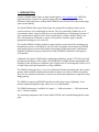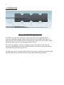
1
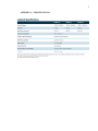
Instruction Manual
Model FP4000
Fiber Optic Strain Gage
No part of this instruction manual may be reproduced, by any means, without the written consent of Geokon, Inc.
The information contained herein is believed to be accurate and reliable. However, Geokon, Inc. assumes no
responsibility for errors, omissions or misinterpretation. The information herein is subject to change without
notification.
Copyright ©2009 by Geokon, Inc.
(Doc Rev. Initial)
Warranty Statement
Geokon, Inc. warrants its products to be free of defects in materials and workmanship, under
normal use and service for a period of 13 months from date of purchase. If the unit should
malfunction, it must be returned to the factory for evaluation, freight prepaid. Upon examination
by Geokon, if the unit is found to be defective, it will be repaired or replaced at no charge.
However, the WARRANTY is VOID if the unit shows evidence of having been tampered with or
shows evidence of being damaged as a result of excessive corrosion or current, heat, moisture or
vibration, improper specification, misapplication, misuse or other operating conditions outside of
Geokon's control. Components which wear or which are damaged by misuse are not warranted.
This includes fuses and batteries.
Geokon manufactures scientific instruments whose misuse is potentially dangerous. The
instruments are intended to be installed and used only by qualified personnel. There are no
warranties except as stated herein. There are no other warranties, expressed or implied, including
but not limited to the implied warranties of merchantability and of fitness for a particular purpose.
Geokon, Inc. is not responsible for any damages or losses caused to other equipment, whether
direct, indirect, incidental, special or consequential which the purchaser may experience as a
result of the installation or use of the product. The buyer's sole remedy for any breach of this
agreement by Geokon, Inc. or any breach of any warranty by Geokon, Inc. shall not exceed the
purchase price paid by the purchaser to Geokon, Inc. for the unit or units, or equipment directly
affected by such breach. Under no circumstances will Geokon reimburse the claimant for loss
incurred in removing and/or reinstalling equipment.
Every precaution for accuracy has been taken in the preparation of manuals and/or software,
however, Geokon, Inc. neither assumes responsibility for any omissions or errors that may appear
nor assumes liability for any damages or losses that result from the use of the products in
accordance with the information contained in the manual or software.
CONTENTS
FIBER OPTIC STRAIN GAGE ...................................................................................................................1
1. INTRODUCTION ...........................................................................................................................................1
2. CONSTRUCTION ...........................................................................................................................................2
3. INSTALLATION .............................................................................................................................................3
3.1 INSTALLATION BY BONDING TO STEEL, COMPOSITE OR CONCRETE SURFACES ..............................................3
3.2 CABLE PROTECTION AND TERMINATION ......................................................................................................3
4. TAKING READINGS.....................................................................................................................................4
4.1 THE OPSENS PICOSENS PORTABLE READOUT BOX .......................................................................................4
4.2 TEMPERATURE CORRECTIONS ......................................................................................................................4
LIST of FIGURES, TABLES and EQUATIONS
FIGURE 1, THE FP4000 FIBER OPTIC STRAIN GAGE ............................................................................................... 2
FIGURE2, PICOSENS READOUT BOX ....................................................................................................................... 4
1
1. INTRODUCTION
Geokon’s FP4000 Strain Gages are built around Opsens’ (www.opsens.com), OSP Fiber
Optic Strain Gage. Opsens’ new patent pending fabrication process ensures an exact
definition of the gauge factor, making the FP4000 the most accurate fiber-optic strain gauge
sensor in the industry.
The Model FP4000 Fiber Optic Strain Gages are designed for bonding to either steel or
concrete surfaces or for embedment in concrete. They are particularly suitable for use in
environments where it may be difficult to use conventional types of strain gages because of
space considerations, high levels of electrical interference or where intrinsic safety is an
issue. Measurements of dynamic events are also possible with these gages using the
appropriate dataloggers, (see section X).
The Geokon FP4000 is highly suitable for smart structure research activities and long term
monitoring in corrosive environment. Used for static or dynamic measurement, the FP4000
strain gauge delivers accurate and reliable measurement in high temperature, high ElectroMagnetic and Radio Frequency Interference fields (EMI/RFI), and nuclear and explosive
environments.
Combined with Opsens’ WLPI signal conditioning technology (patent #7.259.862) and with
the inherent advantages of fiber optics, the FP4000 delivers unprecedented repeatability and
reliability in the most adverse conditions such as high levels of electromagnetic fields as well
as high voltage and rapid temperature cycling conditions.
The FP4000 strain gages have a very low coefficient of thermal expansion and can be used to
measure both mechanical and thermo-mechanical strains in a variety of different materials.
They also are completely insensitive to transverse strains and temperature as opposed to fiber
Bragg gratings.
The FP4000 is immune to EMI,RFI interference and voltage surges, (lightning). It can
transmit signals through fiber optic cables over very long distances.
The FP4000 strain gage is available in 3 ranges: +/- 1000 microstrain, +/- 2500 microstrain
and +/- 5000 microstrain.
For measuring temperatures the Geokon Model FP4700 can be installed alongside the strain
gage.
2
2. CONSTRUCTION
Figure 1, The FP4000 Fiber Optic Strain Gage
The FP4000 is comprised of a miniature Fabry-Perot strain sensor embedded inside a
composite carbon fiber laminate made of uniaxial fibers to form a highly stable sensor, A
fiber optic cable, also embedded in the wafer connects the strain sensor to a portable readout
instrument, (Model Picosens), or datalogger, (Model Prosens).
The version for bonding to steel has a roughened surfaceon the adhesive side while the
version for embedding in concrete has roughend surfaces on both faces and scalloped edges
for optimum keying into the concrete mix.
The fiber optic cable is a specially armored cable of a spiral steel construction which has high
flexibility and provides excellent protection to the signal cable during installation.
3
3. INSTALLATION
3.1 Installation by bonding to steel, composite or concrete surfaces
The Geokon Model 4000 FP strain gage is designed to be epoxy bonded to various materials.
The sensor itself is bonded between two uniaxial carbon fiber strips. These strips are, in turn,
bonded to the substrate under study using different types of epoxy.
For bonding to steel, Loctite Model H4500 Speedbonder is recommended. The steel surface
should be fresh and clean and the gage should be lightly clamped in place during the cure to
maintain a thin glue line. For long term outdoor use the gage area should be covered with a
water resistant mastic or paint to maintain the integrity of the area around the gage and the
glue.
For bonding to composites such as epoxy and carbon fibers, Aerospace Composite Products
E-Z LAM epoxy laminating resin is recommended. This is a two part mix that also requires
light clamping. As with the Speedbonder the gage area should be protected from the weather.
This resin can be used as an overcoat.
For bonding to concrete, Devcon Model 11800UW underwater putty is recommended. This
material is a two part thixotropic epoxy putty that works very well in harsh environments.
The concrete surface should be ground clean before applying the epoxy and the sensor should
be lightly clamped in place during the curing.
Gage trimming. The length of the gage cannot be changed but the width can be trimmed
down to as little as ½”. This can be done by sanding, being sure to take equal amounts from
each side of the strip.
Thermal coefficients. The thermal coefficient of the gage is approximately -0.85 to -1.22
microstrain / deg C. The coefficient of the assembly on 4140 steel is
10.72 microstrain/deg C. For other materials it is recommended that a thermal test be
conducted on a sample of the material under study to determine its free field thermal
coefficient.
3.2 Cable Protection and Termination
The fiber-optic cable from the strain gages can be protected by the use of Model FP-1-3
3mm diameter flexible steel-spiral conduit, which can be supplied by Geokon.
Cables are supplied in customer specified lengths and are equipped with fiber-optic
connectors. If cables are damaged and need splicing together the repair is not an easy task
and special tools are required. These splicing kits are available from fiber-optic cable
suppliers.
4
4. TAKING READINGS
4.1 The Opsens Picosens Portable Readout Box
The FP Fiber-optic Strain Gages are read by means of the Picosens readout Box
The PicoSens is a compact and portable signal conditioner to
be used with any of Opsens’ interferometric fiber optic sensors,
i.e. the WLPI fiber optic sensors, for temperature, pressure,
strain, and position measurements. At the heart of the PicoSens
is the Opsens’ White Light Polarization Interferometry (WLPI)
technology (patent #7.259.862) which provides a mean for
making accurate and absolute measurements of the path length
difference of any type of interferometric fiber optic sensors,
whose difference varies according to the measurand of interest.
The PicoSens is equipped with a large visible LCD display and
can be battery operated. It comes with a standard ± 5 V output
and a RS-232 communication port for real-time data
acquisition. The PicoSens can be controlled directly using the
front-panel keypad or remotely using the standard RS-232
interface. A rugged casing with a removable rubber boot
provides good mechanical protection against intensive
handling in tough environments.
Figure2, Picosens Readout Box
The PicoSens is compatible with all Opsens WLPI sensors
hence providing a multi-purpose tool for measuring various
parameters. With a 20 Hz sampling rate, a ± 0.003 % full scale
resolution and a ± 0.01 % full scale precision the PicoSens
delivers the performances needed for a wide range of critical
measurement applications.
The strain gages plug directly into this box and the displayed output is in microstrain after the
entry of gage factors supplied with the strain gages.
A full description of the Pcosens readout box is provided in the Picosens User Manual
supplied with the equipment.
4.2 Temperature Corrections
Temperature variations of considerable magnitude are not uncommon, particularly during
concrete curing; therefore it is always advisable to measure temperatures along with the
measurement of strain. Temperature induced expansions and contractions can give rise to
real changes of stress in the steel, composite or concrete if the strain-gaged member is
restrained in any way, and these stresses are superimposed on any other load related stresses.
Temperatures can be measured using an Opsens Model OTG fiber-optic temperature sensor
positioned next to the strain gage.
5
APPENDIX A - SPECIFICATIONS