1
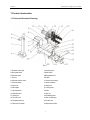
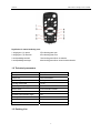
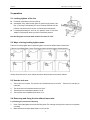
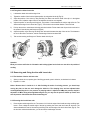
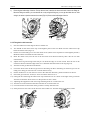
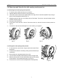
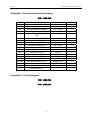
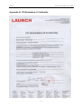
2012-08-03 V1.00.000 Launch TWC-802 tire changer user’s manual photocopying, recording or otherwise, without the prior written permission of LAUNCH. The information contained herein is designed only for the use of this unit. LAUNCH is not responsible for any use of this information as applied to other units. Trademark Information LAUNCH is a registered trademark of LAUNCH TECH. CO., LTD. (short for LAUNCH) in China and other countries. All other LAUNCH trademarks, service marks, domain names, logos, and company names referred to in this manual are either trademarks, registered trademarks, service marks, domain names, logos, company names of or are otherwise the property of LAUNCH or its affiliates. In countries where any of the LAUNCH trademarks, service marks, domain names, logos and company names are not registered, LAUNCH claims other rights associated with unregistered trademarks, service marks, domain names, logos, and company names. Other products or company names referred to in this manual may be trademarks of their respective owners. You may not use any trademark, service mark, domain name, logo, or company name of LAUNCH or any third party without permission from the owner of the applicable trademark, service mark, domain name, logo, or company name. You may contact LAUNCH by visiting LAUNCH at http://www.cnlaunch.com, or writing to Launch Industrial Park, North of Wuhe Rd., Banxuegang, Longgang, Shenzhen, Guangdong, P. R. China, to request written permission to use Materials on this manual for purposes or for all other questions relating to this manual. Neither LAUNCH nor its affiliates shall be liable to the purchaser of this unit or third parties for damages, losses, costs, or expenses incurred by purchaser or third parties as a result of: accident, misuse, or abuse of this unit, or unauthorized modifications, repairs, or alterations to this unit, or failure to strictly comply with LAUNCH operating and maintenance instructions. LAUNCH shall not be liable for any damages or problems arising from the use of any options or any consumable products other than those designated as Original LAUNCH Products or LAUNCH Approved Products by LAUNCH. General Notice Other product names used herein are for identification purposes only and may be trademarks of their respective owners. LAUNCH disclaims any and all rights in those marks. Copyright Information Copyright © 2012 by LAUNCH TECH. CO., LTD. All rights reserved. No part of this publication may be reproduced, stored in a retrieval system, or transmitted in any form or by any means, electronic, mechanical, i Launch TWC-802 tire changer user’s manual Thank you for buying and using this tire changer. This introduction is the important information for this kind of production. Please read the instruction carefully before using or fixing the machine. Please take good care of it. So that it can develop it advantages. Safe rules z z z z z z z The machine should be fixed in a safe place according to the safe rule. The position must ventilate and be sure that there is enough space around it. If we put the machine is in the open air. You must put up a shed to prevent it from the sun, the rain. You shouldn’t use it, when there are inflammable cargo and perishable goods around it. Don’t fix the machine in a place where it is too hot or too wet. Too much dust ammonia alcohol thinner or spray and bond are not allowed on the surface of the machine. If you want to operate the machine without cutting off the electricity .You should have the specialize knowledge. The person without being trained can’t operate the machine. When using this machine .If you are not the people who operate the machine. Don’t stand close to the warning sign .Don’t remove it. If you operate the machine incorrectly. Our company will not be responsible for it. ii Launch TWC-802 tire changer user’s manual Table of contents 1 Product Instruction .................................................................................................................................................. 1 1.1 External Structural Drawing ................................................................................................................................ 1 1.2 Technical parameters.......................................................................................................................................... 2 1.3 Packing List ........................................................................................................................................................ 2 2 operation ................................................................................................................................................................... 4 2.1 Locking tighten of the tire.................................................................................................................................... 4 2.2 Ways of using locking tighten paws. ................................................................................................................... 4 2.3 Use the tool arm: ................................................................................................................................................ 4 2.4 Removing and fixing the tire without inner tube. ................................................................................................. 4 2.4.1 Reducing the pressure and lubricating........................................................................................................ 4 2.4.2 Removing the tire without inner tube........................................................................................................... 5 2.4.3 Fixing the tire without inner tube ................................................................................................................. 6 2.5 Removing and fixing the tire with inner tube. ...................................................................................................... 6 2.5.1 The lubricant of the tire with inner tube. ...................................................................................................... 6 2.5.2 Removing the tire with inner tube................................................................................................................ 6 2.5.3 Fixing the tire with inner tube. ..................................................................................................................... 7 2.6 Removing and fixing the tire with opening mouth press bar ............................................................................... 8 2.6.1 Removing the tire with opening mouth press bar........................................................................................ 8 2.6.2 Fixing the tire with opening mouth press bar............................................................................................... 8 3 Maintenance.............................................................................................................................................................. 9 3.1 General Maintenance ......................................................................................................................................... 9 3.2 Storage ............................................................................................................................................................... 9 Appendix I: Operational principle drawing ............................................................................................................. 10 Appendix II: Circuit diagram..................................................................................................................................... 10 Appendix III: CE Declaration of Conformity ............................................................................................................ 11 iii Launch TWC-802 tire changer user’s manual 1 Product Instruction 1.1 External Structural Drawing Fig 1.1 1.Moveable control part 2.Crossing switch 3.Block plate switch 4.Pedal switch 5.Electrical switch 6.Mixing electric box 7.Tool box 8.Oil tank 9.Hydraulic pressure valve 10.Circumvolve envelop 11.Pressure watch 12.Worm wheel box 13.Belt cover 14.Swing arm 15.Block plate 16.Locking paws 17.Decompression 18.Plate 19.Orientation part 20.Tool arm 21.A lifting car 22.Paralleling board 23.Tool arm hook 24.Tool arm slide way 25.Paralleling side way 26.Condole ear 27.Telecontrol controller 28.Telecontrol receiver 1 Launch TWC-802 tire changer user’s manual Fig1.2 Signification for remote handle key-press 1 swinging arm (14) upward 5 Four blocking paws open 2 swinging arm (14) downward 6 Four blocking paws close 3 small paralleling board left 7 four blocking paws will turn in clockwise 4 small paralleling board right 8 four blocking paws will turn in anti-clockwise direction 1.2 Technical parameters Specifications Parameters Lift height 830~1500mm Exterior size 2400×1920×830mm Machine weight 1600kg The range of bold plate 14”~56” Hydraulic pressure pump power unit 1.1kw 220v/380v/1PH/3PH Gearbox motor 2.2kw 220v/380v/1PH/3PH Speed 7.34 r/min Moveable control operation supply 24V The range of the iron circle 14”~56” Max wheel diameter 2300mm Max wheel width 1065mm 1.3 Packing List 2 Launch TWC-802 tire changer user’s manual SN Part Number Description Quantity TWC-802 tire changer 1set 2 Operation Manual 1 pc 3 Crowbar 2 pcs 4 Assist clip 1 pc 5 Remote controller 1 pc 6 Aluminum protector 7 Extended rod 1 1set/4pcs 1set/4pcs 3 Remark Launch TWC-802 tire changer user’s manual 2 operation 2.1 Locking tighten of the tire z z z Put the tire on the lifting car and move the car. Automatically fixing heart blocking plate will produce high pressure (see Fig2.1).The range of the adjusting is 2-20 mp. Pressure watch will show the pressure. If the wheel circle is very thin. You should reduce the pressure. If mounting/demounting the truck tire, the pressure meter is lower than 18Mpa, turn the pressure switch up so that to increase the pressure. Note: Blocking plate can lock all kinds of wheel circle from 14” to 56”. Fig2.1 2.2 Ways of using locking tighten paws. There are four locking tighten paws in the blocking plate. It can lock the different kinds of wheel circle. There are many different kinds of ways of locking according to the wheel (see the following pictures). Usually vacuum tire use the 1 and 2 methods and the tire with press bar use the 3 and 4 methods. 2.3 Use the tool arm: 1) 2) 3) 4) The tool arm has four holes. The first hole can mount/demount the tire of 40-56〞. Enter the 2-4 hole after you rotate 360° The second hole can mount/demount the tire of 30-40〞. The third hole can mount/demount the tire of 22-36〞. The fourth hole can mount/demount the tire of 14-22〞 2.4 Removing and fixing the tire without inner tube. 2.4.1 Reducing the pressure and lubricating. 1) 2) Check if the locking tighten hook hooks the lifting board. The removing and fixing hook mustn’t be in the position of working. Make sure the tire has been clipped; there is no air in the tire. 4 Launch 3) 4) 5) 6) TWC-802 tire changer user’s manual Adjust the position of the tire. The plate has just been away from the rim. Make it be close to the rim. When you turn around the tire, move the tool arm and press the tire down until tire is separated with the rim. Put more lubricant between the rim and edge of the tire. Make the plate prick up the tool arms, put the plate on the other side of the tire, until other side of the tire is separated with the rim, put some lubricant in it. Pay attention: Lubricant must be put. When you reduce the pressure outside you should follow anti-clockwise direction. When you reduce the pressure inside, you should follow clockwise direction. When you reduce the pressure inside, removing and fixing hook must be in the position of Fig2.2. Fig2.2 2.4.2 Removing the tire without inner tube 1) 2) 3) 4) 5) 6) Move the tool arm to the outside of the tire , make removing hook face the tire Make sure that locking tighten hook has tightened . Orientation parts are in its position. Adjusting the position between removing hook and the tire. The removing hook must be in the position between the edge of the tire and the rim. Move the fool arms so that the removing hook can insert the tire at the same time, it can pull the edge of the tire outside. Press the tire , move the tool arms outside little by little .Repeat this action , let the removing hook swing downward so that the removing hook can pull the edge of the tire(see Fig2.3). Turn the tire in the anti-clockwise direction, until the whole tire has been separated. Move the tool arm to the inside pull the edge of the inner tube also moves it to the outside of the rim. Turn the tire , until the edge of inside separated from the rim.(see Fig2.4) We can use plate to remove the edge of the inside tire by pushing the edge of the tire out of the rim. Press the tire down. Make the plate between the rim and the edge of the tire. Turn the tire (Fig2.5). You can see crow to help you. Fig2.3 Fig2.4 Fig2.5 Attention: You must be concentrated, examine the movement parts carefully, and avoid it from damage. Examine the tire when it was weighted. Adjust the position of tool head and rim. Removing and fixing hook must be in the position of 2.3.When you use plates. 5 Launch TWC-802 tire changer user’s manual 2.4.3 Fixing the tire without inner tube 1) 2) 3) 4) 5) 6) 7) Lubricate the wheel circle and the edge of tire. Tighten the outside of the tire in the highest position by using wheel circle clip (Fig2.6). Adjust the position of iron circle by using the lifting car. Make sure that the wheel circle clip is in the highest position of rim. Adjust the angle of the tire, and make the tire and rim cross together. Adjust the position of removing and fixing hook. The position of it must between rim and the edge of the tire. The distance to the edge of tire is about 5mm (Fig2.7). Turn the tire in the clockwise direction. The tire is fixed. Prick up the tool arm; unload wheel circle clip push the tire inside. Fix the wheel circle clip on the rim and turn it to the upward of the removing and fixing hook (Fig2.8). Adjust the position of the removing and fixing hook and make it between the edge of tire and rim. The distance to the rim is about 5mm.Turn the tire, until the outside edge of the tire has been fixed. Take out the removing and fixing hook. Take the wheel circle clip out. Fig2.6 Fig2.7 Fig2.8 Attention: When you remove and fix the tire. Orientation and Locking tighten hook of tool arm must be in the position of working. 2.5 Removing and fixing the tire with inner tube. 2.5.1 The lubricant of the tire with inner tube. 1) 2) When you let the air out, open the pipe of the fixing gas mouth, press it in the tire, so that there isn’t obstruct. Repeat 2.4.1 action. Notice: Because there is inside tire in it. After finishing the action of reducing pressure, you should stop moving the plate, so that use won’t damage the inside tire. The clamping force can been adjusted when mounting/demounting the tire, the pressure of pumping station is adjusted to 20Mpa,the pressure relay30 is adjusted to 18 MPa, during mounting/demounting the tire, you may turn the pressure switch up. Please must turn the pressure switch down after finish demounting tire. 2.5.2 Removing the tire with inner tube. 1) Removing the outside edge of the tire. The same as 2.4.2.Hook the edge of the tire with removing and fixing hook. Insert a crown, sledge the outside edge of the tire by pressing the crown down and lower the tire down. The distance between the head of the removing and fixing hook and the edge of the tire is about 5mm (Fig2.9). Turn the tire in the anti-clockwise direction; you can remove the outside edge of the tire. 6 Launch 2) TWC-802 tire changer user’s manual Removing the inside edge of the tire: Pick up the tool arm, lower the tire down and make it touch the lifting car. Move the lifting car outside, you can take the tire out by using the lifting car, you can get the inside tire out. After doing it, the action is just the same as the course (Fig2.10).Remove the inside edge of the tire. Fig2.9 Fig2.10 2.5.3 Fixing the tire with inner tube. 1) 2) 3) 4) 5) 6) 7) 8) 9) 10) 11) 12) 13) 14) Put some lubricant on the edge of the tire and the rim. You should fix the wheel circle clip in the highest place of the rim. Make sure the wheel circle clip block the wheel circle (Fig2.11). Put the tire on the lifting car. Lower the wheel circle (wheel circle clip must be in the highest position). Make the wheel circle hook the side of the tire. Raise the wheel circle; turn the tire in the anti-clock wise direction little by little. The tire can lean automatically. Adjust removing and fixing hook and you can hook the edge of it from inside. Turn the tire in the clockwise direction until the edge of the tire is finished. Take the wheel circle clip (Fig2.12). Turn the tire the gas hole faces the bottom. Lower the wheel circle let the tire get close to the lifting car. Move the lifting car outward, you can use lifting car to help you move the tire a certain distance away. Put the inside tire in it. Turn the iron circle in the clockwise direction, put the inside tire in the rim. Put a little gas in the tire. So that, it won’t be broken when we fix it. Lifting the tire and fixing the wheel circle clip outside the rim. It is 20cm to the right of the gas mouth. Turn the tire until the wheel circle is in the position of nine o’clock. Adjusting the equipment of the removing and fixing hook. It is 5mm to the rim. Turn the tire in the clockwise direction until the tire is fixed on the rim. Lower down the tire and check if the gas hole is exactly faces the hole. If the position is mot exact, let the tire lean on the lifting car. Turn the wheel circle little by little. Fig2.11 Fig2.12 7 Launch TWC-802 tire changer user’s manual 2.6 Removing and fixing the tire with opening mouth press bar 2.6.1 Removing the tire with opening mouth press bar 1) 2) 3) 4) 5) 6) 7) Fix the tire as above. Make sure there is no air in the tire. Adjust the plate and make it face to the tire, and get close to it. Turn the tire, and move the tool arms towards inside. If the edge of the tire has been separated. Stop moving so that we couldn’t damage the inside tire (Fig2.13). Sledge the press bar with crow in the opening and pull if with plate. Turn the tire in the anti-clockwise until the press bar to fall down (Fig2.14). Insert gas mouth inside the tire. Put the plate on the other side of the tire. Push and turn the tire, until half of the tire has been pushed out (Fig2.15). Lower the tire, make tire touch the lifting tire car, move if outside, you can get tire. Fig2.13 Fig2.14 Fig2.15 2.6.2 Fixing the tire with opening mouth press bar. 1) 2) 3) 4) 5) 6) Fix the wheel circle; put the hole in the gas mouth in the bottom. Brush lubricant in it. Put the tire with inside tire on the lifting car the gas mouth should be put in the bottom. Move the lifting car; make the tire enter the iron circle. You can turn the circle little by little. Adjust the position of the gas mouth. Make the plate face the tire, press the blocking circle and the opening mouth press bar. Turn the tire and the fixing is over (Fig2.16). Prick up arm tools, remove tire (Don’t charge the tire on the equipment). 8 Fig2.16 Launch TWC-802 tire changer user’s manual 3 Maintenance 3.1 General Maintenance z z z z z z z z You must follow the instructions on cleaning periodically. You should cut off the power supply. Clean the machine itself and the movement parts (slide way, blocking plate, etc.). Cleaning the following parts periodically by adding some lubricant (slide way, blocking plate, tool head, and Orientation parts of tool head). Change gear wheel oil for worm wheel box. The equipment has sign of putting oil in. Tighter the bolts periodically in fixing parts. 1) Adjusting the bolts periodically in slide way. Make it not only work correctly but also be sure the distance between them. 2) Adjusting the bolts in paralleling movement small board (Fig3.1). Tighten the bolts in the upper place of the paralleling movement small board. After using the machine a period of time, push the paralleling movement small board according to the direction (Fig3.2), loosening the fixing bolt on the upper place of the paralleling small board. Adjust the slide block and bolts. Then tighten all the bolts.(The bolts shouldn’t be neither too tight nor loose.) 3) Adjust the bolts in the four paws blocking plate (Don’t be too tighten.) Fig3.1 Fig3.2 Check the tension and tighten of the belt. If it needs adjusting, get down the belt cover adjust the tension and tighten. 3.2 Storage Properly preserved if the machine won’t be used for a long time. 1) Lower the lift boom. 2) Take block plate back. 3) Pull out the electrical plug. 4) Spread oil on the sliding groove of bracket. 5) Clear away the tanker. 6) Spread oil on cross-axle of assembly. 9 Launch TWC-802 tire changer user’s manual Appendix I: Operational principle drawing 错误!未指定主题。 NUMBER MANE MODEL QUANTITY Y1 THICK HYDRAULIC CYLINDER TG¢ 95*200 1 Y2 LING HYDRAULIC CYLINDER TG ¢50*1000 1 Y3 SHORT HYDRAULIC CYLINDER TG¢ 50*380 1 Y4 PRESSING METER Y-40 1 1、2 ASSEMBLY OF SQUARE BEND AND PIPE GPU 6-1-4UMPa1200 2 3、5、6 STRAIGHTWAY FOUND PIPE JOINT GPU 6-1-4UMPa880 3 4 STRAIGHTWAY FOUND PIPE JOINT GPU 6-1-4UMPa1520 1 7 HYDRALIC CYLINDER TIE-IN TG¢ 8*140 1 8 HYDRALIC CYLINDER TIE-IN TG ¢8*105 1 M2 MOTOR Y-90L4 1 F1 HYDRAULIC LOCK TGF-YS6 1 F2 ROTARY PIPE JOINT TGF-HJ4 1 F3 CHECK VALVE TGF-DC6C 1 F4 RELIEF VALVE TGF-YL4-C 1 F5 HYDRAULIC FILTER TGL-M18 1 DF1~DF3 HYDRAULIC SOLENOID VALVE 4WE6E61/CG24 3 C GEAR PUMP CBK-2.5 1 P FEED OIL CIRCUIT T BACK OIL CIRCUIT Appendix II: Circuit diagram 错误!未指定主题。 错误!未指定主题。 10 Launch TWC-802 tire changer user’s manual Appendix III: CE Declaration of Conformity 11 Launch TWC-802 tire changer user’s manual Warranty Order Information THIS WARRANTY IS EXPRESSLY LIMITED TO PERSONS WHO PURCHASE LAUNCH PRODUCTS FOR PURPOSES OF RESALE OR USE IN THE ORDINARY COURSE OF THE BUYER’S BUSINESS. Replaceable and optional parts can be ordered directly from your LAUNCH authorized tool supplier. Your order should include the following information: - Quantity - Part number - Item description LAUNCH electronic product is warranted against defects in materials and workmanship for one year (12 months) from date of delivery to the user. This warranty does not cover any part that has been abused, altered, used for a purpose other than for which it was intended, or used in a manner inconsistent with instructions regarding use. The exclusive remedy for any automotive meter found to be defective is repair or replacement, and LAUNCH shall not be liable for any consequential or incidental damages. Final determination of defects shall be made by LAUNCH in accordance with procedures established by LAUNCH. No agent, employee, or representative of LAUNCH has any authority to bind LAUNCH to any affirmation, representation, or warranty concerning LAUNCH automotive meters, except as stated herein. Customer Service If you have any questions on the operation of the unit, please contact us: Tel: 86-755-84528767 If your unit requires repair service, return it to the manufacturer with a copy of the sales receipt and a note describing the problem. If the unit is determined to be in warranty, it will be repaired or replaced at no charge. If the unit is determined to be out of warranty, it will be repaired for a nominal service charge plus return freight. Send the unit pre-paid to: Disclaimer Attn: Overseas Department LAUNCH TECH. CO., LTD. Launch Industrial Park, North Wuhe Avenue, Banxuegang Industrial park, Longgang District., Shenzhen, Guangdong Province, P. R. China THE ABOVE WARRANTY IS IN LIEU OF ANY OTHER WARRANTY, EXPRESSED OR IMPLIED, INCLUDING ANY WARRANTY OF MERCHANTABILITY OR FITNESS FOR A PARTICULAR PURPOSE. 12


![UB25 Cover+Front Matter [Rev C] -- 1-02](http://vs1.manualzilla.com/store/data/005906297_1-9ba350e3ad2195c1d2103c91c2552cc1-150x150.png)