1
Technical Manual
(NetSafe-DVR)
NetSafe DVR
1. Installation of NetSafe DVR ………………………………….…………………… 4
1.1. Safety Information …………………………………….…………………… 4
1.2. Removing Package …………………………………….…………………… 6
1.3. Rear Panel of System ……………………………………………………… 7
1.4. Camera 75Ohm Terminator ………………………………..………………. 8
1.5. How to connect to PAN/TILT Camera …………………………………… 9
1.6. How to connect to PSTN, ISDN, Leased line & LAN …………….…… 10
1.7. Connecting Outer Sensor …………………………………………………. 11
2. Installation Guide
………………………….……………………………………. 12
2.1. CMOS Setup(P3) ………………….………………………………………. 12
2.1.1 Standard CMOS features ……………………………………………… 13
2.1.2 Advanced BIOS feature ………………………………………………… 14
2.1.3 Advanced Chipset Features …………………………………………… 15
2.1.4 Integrated Peripherals …………………………………………………… 16
2.1.5 Power management Setup …………………………………………… 18
2.1.6 PnP/PCI Configuration Setup ………………………………………… 19
2.1.7 PC Health Status ………………………………………………………… 20
2.1.8 Frequency/Voltage Control ……………………………………………… 21
2.1.9 Save & Exit Setup ………………………………………………………… 22
2.1.10 Exit Without Saving ……………………………………………………… 23
2.2. CMOS Setup(P4) ……………………….……………………………………. 24
2.2.1 Standard CMOS features ……………………………………………… 25
2.2.2 BIOS Features Setup …………………………………………………… 26
2.2.3 Chipset Features Setup ………………………………………………… 27
2.2.4 PnP/PCI Configuration Setup…………………………………………… 28
2.2.5 Integrated Peripherals …………………………………………………… 29
2.2.6 Hardware Monitor Setup ………………………………………………… 30
2.2.7 Supervisor/User Password ……………………………………………… 31
2.2.8 Save & Exit Setup ………………………………………………………… 32
2.2.9 Exit Without Saving ……………………………………………………… 33
2.3. NetSafe-DVR Setting ………………………………………………………. 34
2.4. NetSafe-DVR partition Setting
…….……………………………………. 41
2.5. Install & Reinstall NetSafe-DVR Program…………………………………. 54
-2-
NetSafe DVR
3. System Algorithm ……………………………………………………………………. 64
3.1 System Data Flow …………………………………………………………. 64
3.2 Image Processing Board …………………………………………………. 65
4. Backup Storage Setting ……………………………………………………………. 69
4.1 IEEE-1394 Backup Media …………………………………………………. 69
4.1.1 IEEE-1394 System Architecture ………………………………………. 69
4.1.2 IEEE-1394 HDD & Cable Connect to NetSafe-DVR System ………. 70
4.1.3 IEEE-1394 HDD Setting for WIndows98SE …………………………. 70
4.2 DVD-RAM Backup Media …………………………………………………… 74
4.2.1 DVD-RAM Specification ………………………………………………… 74
4.2.2 DVD-RAM Test ………………………………………………………… 75
4.2.3 DVD-RAM Backup Test ………………………………………………… 76
5. Make a Dial up Connection ………………………………………………………… 78
-3-
NetSafe DVR
1. Installation of NetSafe DVR
This manual includes details on
Appearance and name of NetSafe DVR,
how to connect PAN/TILT control with related tools
and how to setup the program of system.
If you are First user of NetSafe DVR, even though you are experienced with similar products
like this, we recommend you read this manual carefully and follow the instructions inside
before using this product.
Before using NetSafe DVR, you should contact where you purchased and get a support,
in case you open the cover for upgrading of system or repair. If you have any questions or
problem, contact where you purchased.
1.1. Safety Information
-
Before installation, be sure to turn off the power of NetSafe DVR.
Do not open the cover of product at your disposal.
Install the product to a well-ventilated area.
Keep about 20 Cm distance with other products.
Do not install the product where extreme electronic wave or magnetism exit.
If the product is installed near the wireless devices like radio or TV, it may cause
interference.
- Do not expose the product directly to the sun or heating apparatus.
- Do not expose the product to rain, extremely humid or dirt environment. It might cause
malfunction of System. Install dehumidifier and use compressed air for cleaning filter
every 3 months. Cleaning every fan, major parts of system inside.
- Re-insert front filter after Cleaning & drying it every 3 months.
- Keep the product away from tremor or any magnetic devices.
- Do not install the product to extremely cold area.
- Pay attention not to slip an electronic conductor into the groove of the product for
ventilation.
-4-
NetSafe DVR
- Correctly adjust the input voltage switch of power supply according to your
environment.
- Use stable Transformer to protect malfunction of system, where expected
unstable power supply.
- When you install, put another support for BNC cable, not to damage BNC Board.
it might be damaged by the weight of BNC cable.
-5-
NetSafe DVR
1.2. Removing Package
After removing NetSafe DVR package , place NetSafe DVR where you want to install.
(Read carefully safety information before installation)
Make sure that the following contents before start install.
-
Body (NetSafe DVR)
A power supply cable
User’s Manual
Keyboard, Mouse
Case accessory Box
Microsoft Windows 2000 License
Communication conversion cable(Receiver connecting cable)
NetSafe DVR
Body (NetSafe DVR)
Keyboard
Power supply Cable (for AC)
Mouse
-6-
NetSafe DVR
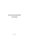
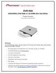
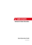
1.3. Rear Panel of System
a
e
f
g h
i
b
j k
c
lm n o p
a. Camera Input (CH1~CH16) / Output (CH1~CH16)
b. Camera 75Ohm Terminator
c. Control Output (Com:4port, Control:16port)
d. Sensor Input (Com:4port, Sensor:16port)
e. AC Power Input (AC 110 ~ 220V)
f. PS/2 Mouse Port
g. PS/2 Keyboard Port
h. USB Port
i. Com A Serial Port
j. LPT(Printer) Port
k. Com B Serial Port
l. Line Out 1
m. Line In / Line Out2
n. MIC In
o. Game Port
p. VGA Out
q. TV Out (Composite Out)
r. RS422/485 (RX Connection Port)
s. LAN Port
-7-
d
q
r
s
NetSafe DVR
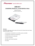
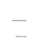
1.4. Camera 75 Ohm Terminator
This system can connected to CCTV 16 channel input with one by one Loopback.
Use output port of each channel.
ON
1
ON
2
3
4
5
6
7
8
9 10 11 12 13 14 15 16
All the channel set as ‘On’, when it is released from warehouse.
Set ‘On’ all the channel when you don’t use CCTV.
About the channel which will be used by CCTV, set the switch ‘Off’ like above picture.
Turn the switch ‘On’ when you don’t use CCTV.
-8-
NetSafe DVR
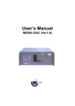
1.4. How to Connect to PAN/TILT Camera
485
Signal Line (+)
a ground
Signal Line (-)
RX LED (Green)
TX LED (Red)
Operation LED (Green)
- Connect to PAN/TILT Receiver (RS-485 Signal line)
- Only when Operation LED is ‘On’ state,
image appears normally.
- Caution : When connect, pay attention (+), (-) polarity of signal line
-9-
NetSafe DVR
1.5. How to Connect to PSTN, ISDN, Leased line & LAN
Connecting to COM 2
port
( 9 PIN )
LAN port
Ethernet
A/C ADAPTER
RS-232(25Pin)
D.S.U(Modem)
Leased Line(ISDN)
D.S.U(Modem)
COM2
PRINTER
PC in Center
A/C ADAPTER
-10-
NetSafe DVR
1.6. Connecting Control Output
COM
Control Out ( 1 ~ 16)
Con.
(-)
(+)
External Power Supply ( DC 12V)
Siren, Alarm, Outside relay
When it is controlled automatically or activated by motion or sensor, control output port
(You can control at “Settings – Sensor & Output Setup”) connect to the “COM” port .
- Maintained “NO(Normal Open)” at normal time.
- Maintained “NC(Normal Close)” at control output Time.
Only use below 12V, 300mA voltage. When you control electric lamp and other devices,
use another outer relay control.
1.7. Connecting Outer Sensor
COM
Sensor Input ( 1 ~ 16)
Sen.
Connect one signal line of all kind of sensor(infrared rays sensor, thermic rays sensor,
Magnetic sensor) to the com port of the body and connect another signal line to the
desired sensor number.
- Set the type of sensor at “Sensor & Output Setup”.
Use another adapter(Power Supply) for the all sorts of sensor’s power supply.
-11-
NetSafe DVR
2. Installation Guide
This chapter explains a proper activation of NetSafe DVR, how to add HDD and other
basic system setup.
2.1. CMOS Setup
Initial screen of CMOS Setup
To see the screen like above, turn it on the NetSafe-DVR Power Switch then ‘Del’ key on
keyboard. After a seconds, initial CMOS setup screen be displayed like figure {2-1], Select
‘Load Optimized Defaults’ out of menu. This sets your system basically optimized status.
On your optimized system, set the function as following pictures.
-12-
NetSafe DVR
2.1.1. Standard CMOS Features
Set the basic information of HDD.
Standard CMOS Features
* Primary Master / Primary Slave, Secondary Master / Secondary Slave
Can use 4 IDE type HDD. Because it delivered 1 HDD from warehouse
Except Primary Master, rest of HDD type is set “None”.
To add additional HDD set “Auto” type then when your PC reboots, HDD sets
automatically.
* Halt On
Set when your system will be halt on if it detects unexpected error.
- All Errors : System will be halt on every kind of error.
-13-
NetSafe DVR
2.1.2. Advanced BIOS Features
Set the function of advanced BIOS.
Advanced BIOS Features
* BIOS Flash Protection
Set write protect on Flash BIOS.
* First / Second / Third Boot Device
Set the order of booting disk.
* HDD S.M.A.R.T. Capability
S.M.A.R.T. (Self Monitoring, Analysis, Reporting Technology) has the function of
keeping the most suitable status of DATA with watching and analyzing the System.
-14-
NetSafe DVR
2.1.3. Advanced Chipset Features
Set the advanced chipset function.
Advanced Chipset Features
Keep the default value on this menu.
-15-
NetSafe DVR
2.1.4. Integrated Peripherals
Set the formation of IDE and other peripherals.
Integrated Peripherals
* USB Controller
Select whether you use USB controller or not.
* Init Display First
Select pre-selected slot when you use AGP, PCI, ISA and ISA VGA Card together
on your system.
* AC97 Modem
Select whether you use built-in modem card or not.
-16-
NetSafe DVR
Integrated Peripherals
* Onboard Serial Port 1 / 2
Set the address of built-in serial port manually or automatically.
* Onboard Parallel Port
Set the address of built-in parallel port manually or automatically.
* Parallel Port Mode
Set the port of printer.
* AC Back Function
Select the power on/off and last status when a power supplies again after
power failure.
-17-
NetSafe DVR
2.1.5. Power Management Setup
Set the power management of System.
Integrated Peripherals
* Modem Use IRQ
Set the IRQ for modem.
-18-
NetSafe DVR
2.1.6. PnP/PCI Configuration Setup
Set the value of IRQ of PCI, ISA devices.
PnP/PCI Configuration Setup
Keep the default value on this menu.
-19-
NetSafe DVR
2.1.7. PC Health Status
Shows the inside of PC hardware.
PC Health Status
Keep the default value on this menu.
-20-
NetSafe DVR
2.1.8. Frequency / Voltage Control
Set the Ratio of CPU.
Frequency/Voltage Control
* Auto Detect DIMM/PCI Clk
Set DIMM/PCI Clk automatically.
-21-
NetSafe DVR
2.1.9. Save & Exit Setup
Save the changed value, exit Setup program.
Save & Exit Setup
-22-
NetSafe DVR
2.1.10. Exit Without Saving
Exit Setup program without Saving.
Exit Without Saving
-23-
NetSafe DVR
2.2. CMOS Setup(Pentium-4)
Initial CMOS Setup
Power on NetSafe-DVR and press DEL key for CMOS setup screen like [Figure 2-2-1].
Select ‘Load Optimized Defaults’ on the menu. Performing this function makes your
system as optimized setting. Set your system function properly on basically optimized
state. Set the function as following steps.
-24-
NetSafe DVR
2.2.1. Standard CMOS Features
General H/W setup.
Standard CMOS SETUP
* Primary Master / Primary Slave, Secondary Master / Secondary Slave
4 additional HDD( IDE type) available.
Because 1 HDD installed in your system, rest HDD set as ‘NONE’ except Primary Master.
Additional HDD will be automatically added when you system boots. To do this, set the
rest of HDD type as ‘Auto’.
* Halt on
Check Halt on menu as ‘All errors’.
-25-
NetSafe DVR
2.2.2. BIOS Features SETUP
Set advanced BIOS function
BIOS Features SETUP
* 1st / 2nd / 3rd Boot Device
Set the order for booting devices
* Interrupt Mode
PIC : minimize interrupt and error
Set interrupt mode as ‘PIC’
* HDD S.M.A.R.T. Capability
S.M.A.R.T. (Self Monitoring, Analysis, Reporting Technology) has the function that
HDD analyze status of system and keep the best data keeping condition.
* Full Screen Logo show
check whether you want to show logo screen when system boots.
set this menu as ‘Disable’
-26-
NetSafe DVR
2.2.3. Advanced Chipset Features SETUP
Set advanced Chipset function
Advanced Chipset Features SETUP
* Leave this setup as default.
-27-
NetSafe DVR
2.2.4. Integrated Peripherals
Set IDE & peripheral devices.
Integrated Peripherals
* USB Controller
Check whether you use USB port or not.
Set ‘Disable.’.
* Init Display First
In case of onboard VGA system, you don’t need to select this. But in this system
you should select ‘AGP’ type.
* AC97 Audio
Check whether you will use on board sound.
Set ‘Disable’
* AC97 Modem
Check whether you will use on board modem.
Set ‘Disable’
-28-
NetSafe DVR
2.2.5. Integrated Peripherals
.
Integrated Peripherals
* Onboard Serial Port 1 / 2
Set the address of serial port manually or automatically.
Set Onboard Serial Port 2 as ‘Disabled’.
* Parallel Port Mode
Set the address of parallel port manually or automatically.
Set the printer mode..
Set Parallel Port Mode as [ECP+EPP].
* AC Back Function
When there is irregular power shut down, it memorizes last status and work.
Set AC Back Function as ‘Memory’.
-29-
NetSafe DVR
2.2.6. Power Management Setup
Power Management Setup
* Modem Use IRQ
Set IRQ which you will use Modem.
Set this menu as [NA]
* Soft – off by PWR – BTTN
Delay 4 Sec – In case of system is working, it turns soft-off with pressing power
button for 4 sec.
-30-
NetSafe DVR
2.2.7. PnP/PCI Configuration Setup
Set the value of IRQ PCI, ISA devices.
Enter new supervisor password :
PnP/PCI Configuration Setup
This field enables management of PnP compatible devices. When you set ‘Auto’, IRQ
& DMA bios will be set automatically. When you set ‘Controlled by’, dialog will
appears like above picture. Set ‘Manual’.
-31-
NetSafe DVR
PnP/PCI Configuration Setup
If you set ‘Manual’ in Resources Controlled By, user can adjust IRQ Resources.
Select ‘Press Enter’.
-32-
NetSafe DVR
PnP/PCI Configuration Setup
To protect error, set IRQ 4 & 7as ‘Reserved’.
* PC Health Status & Frequency / Voltage Control
Follow default settings.
-33-
NetSafe DVR
2.2.8. Save & Exit Setup
Save changed value and exit CMOS.
SAVE to CMOS and EXIT(Y/N)? Y
Save & Exit Setup
Select ‘Save & exit’ or press F10 key, then type ‘y’ and press enter. CMOS setup is
completed.
-34-
NetSafe DVR
2.3. NetSafe-DVR Setting
1. Insert Windows2000 Professional Bootable CD and follow the instruction.
- Boot with CD -> partition of ‘C’ root : 3GB, file system : NTFS
2. Install Driver
- Set VGA Card, Sound Card, Capture board etc. driver. (saved at C:\Backup)
3. Set HDD partition (file system : FAT32)
* See the 2.4 Partition Setting
- computer management -> storage -> disk management
Set as Extended drive -> Make 5 partitions as logical drive and format them.
-35-
NetSafe DVR
4. Change default setting of Windows
a. Click right mouse button on Desktop screen and select properties -> display
properties
-> setting -> colors(True Color(32bit)), screen area(1024X768).
b. Change the detail option of ‘Power options properties’ like a following pictures.
Set Screen Saver as ‘None’.
Figure 2-3-1
Figure 2-3-2
-36-
NetSafe DVR
Click ‘Setting’ button on ‘Screen Saver’ tab menu and then following picture
appears. Set every field like a picture. If you don’t set like a picture, system
might goes to power saving mode and nothing would be displayed on the
screen.
Figure 2-13 Power Options Properties
c. Recycle Bin setting -> properties -> check ‘Do not move files to the Recycle Bin’ &.
‘Remove files immediately when deleted’.
d. Event log setting : administrator tool -> event viewer -> check ‘Overwrite events as
needed’.
-37-
NetSafe DVR
Figure 2-3-3
Figure 2-3-4
e. control panel -> Don’t check ‘Enable pointer shadow’ option.
Figure 2-3-5
-38-
NetSafe DVR
f. control panel -> users & passwords setting .
Figure 2-3-6
5. directX8.0 install (saved at c:\Backup directory)
- Download Windows 2000 drivers from www.microsoft.com and then install it.
6. Install Windows2000 Service pack 2. (saved at c:\Backup directory)
- Download it from www.microsoft.com and then install it.
7. Install Language pack (Option)
- After installing language pack, select desired language and set it as default language
at control panel -> global setting and then restart system.
-39-
NetSafe DVR
8. NetSafe-DVR installation (saved at c:\Backup directory)
- Install program with using installation CD.
- Choose correctly channel(16ch or 8ch) -> cpu type(P-III or P-IV) ->
video type(NTSC or PAL) -> DVR board(TW99 or TW98) according to your system.
Figure 2-3-7
Figure 2-3-8
-40-
NetSafe DVR
Figure 2-3-9
Figure 2-3-10
9. The End NetSafe-DVR Series Setting. Thank you.
-41-
NetSafe DVR
2.4. NetSafe-DVR Partition Setting
1. Start -> settings -> Control panel -> administrator tools -> computer management
Figure 2-4-1
-42-
NetSafe DVR
2. Storage -> disk management
2.1. Click right mouse button at “unallocated partition” -> create partition
Figure 2-4-2
2.2. Click Next -> select the “Extended partition” type -> Next
Figure 2-4-3
Figure 2-4-4
-43-
NetSafe DVR
2.3. Choose a partition size of disk space to use -> click Finish
Figure 2-4-5
Figure 2-4-6
2.4. Now, your partition is “Free Space”. -> mouse right button click -> create logical drive.
Figure 2-4-7
-44-
NetSafe DVR
2.5. Now, your partition is “Free Space”. -> Click right mouse button -> create logical drive.
Figure 2-4-8
Figure 2-4-9
2.6. Choose a logical partition size. -> Assign drive letter and path.
Figure 2-4-10
Figure 2-4-11
-45-
NetSafe DVR
2.7. format the partition : select “quick format”, “FAT32” -> finish
Figure 2-4-12
Figure 2-4-13
2.8. You can see that one logical partition created.
-> You must Repeat Figure 2.4.7 ~ Figure 2.4.13 progress. -> Confirm the “Logical
Drive”.
Figure 2-4-14
Figure 2-4-15
* If logical drive is not formatted, you should format it.
-46-
NetSafe DVR
3. HDD Extension
When factory release NetSafe-DVR, 60GB HDD is installed in NetSafe-DVR.
Up to 4 HDDs can be added in the rack like the picture below.
3.1. Mount HDD in rack.
A
B
D
C
Figure 2-4-16 HDD Rack
A : Primary Master
B : Secondary Master
C : Secondary Slave
D : Primary Slave
Up to 4 HDDs are expandable.
- For expansion HDD, we recommend you to follow the orders like picture above.
(order : A->B->C->D).
- Up to 3 HDDs expansion, follow our recommendation. (A:Primary Master, B:Primary Slave,
C:Secondary Master)
- Up to 2 HDDs expansion, A:Primary Master, B:Primary Slave.
-47-
NetSafe DVR
* HDD Jumper : Set Master/Slave mode. When user want to use more HDD, refer to
the manual of a current using HDD.
Following steps are about Segate HDD jumper setting.
Master or single drive
Drive is slave
Master with non ATA compatible slave
Cable select
Limit drive capacity
e.g) Seagate HDD Options jumper block
3.2. Computer Management -> Storage -> disk management
Figure 2-4-17 Disk Management window after installing 4HDDs
-48-
NetSafe DVR
3.3. HDD recognition.
-49-
NetSafe DVR
-50-
NetSafe DVR
3.4. Choose ‘Create Volume’ with clicking right mouse button.
Figure 2-4-18 Create Volume
-51-
NetSafe DVR
-52-
NetSafe DVR
-53-
NetSafe DVR
<NOTE for HDD partition >
In case of that additional backup media is installed in NetSafe-DVR, Windows2000
would recognize your backup media as an ordinary data recording HDD. Not like
Windows’98, part of backup media(IEEE1394) can be recognized as fixed HDD in
Windows2000, and this makes problem that system records data at backup media.
You cannot record data if a device(such as CD-RW) mixed with HDD.
To prevent this, rename the label of a device that you would use as backup media as
‘backup’, and use other name or leave it empty on each HDD partition.
-54-
NetSafe DVR
2.5. Install & Reinstall NetSafe-DVR Program
Follow next steps when you upgrade Operating System or need new installation.
Figure 2-5-1 Install program folder
-55-
NetSafe DVR
Finish NetSafe-DVR program by using Ctrl+Alt+Shift+F4 keys, and then double click
Setup.exe like Figure[2-5-1].
-56-
NetSafe DVR
-57-
NetSafe DVR
-58-
NetSafe DVR
-59-
NetSafe DVR
-60-
NetSafe DVR
* You should restart NetSafe-DVR program after installing NetSafe-DVR program.
-61-
NetSafe DVR
When you upgrade program, first you should delete installed program, and then install
new program. Following steps are about how to delete installed program.
Figure 2-5-2 Uninstall Program
-62-
NetSafe DVR
-63-
NetSafe DVR
You should restart your system after uninstall.
When you try to upgrade your system without restarting, error message would be shown
that you have to restart your system, the program would not be installed.
-64-
NetSafe DVR
3. System Algorithm
For your better understanding overall system, this part explains overall NetSafe-DVR
system, data flow, algorithm of H/W and S/W.
3.1. System Data Flow
This system converts analog signal of camera to digital data, and then records it
into HDD by using MJPEG compression algorithm.
For playback stored data, first decompress stored data and then it is played
by using VGA card.
VIDEO
VGA
Card
VIDEO
…..
Image
Processing
Board
Decompression
Codec
HDD
Compression
VIDEO
Overlay Data Flow
Figure 3-1 Data Flow
-65-
Capture Data Flow
NetSafe DVR
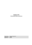
3.2. Image Processing Board
This board converts analog image data to digital data, and then send it to memory
by system data bus, and recorded into HDD after CODEC calculated compressing
process. Following are the functions of this board.
* Image Overlay
* Image Capture
* Sensor & controller I/O
* RS-485 communication(Pan/Tilt)
* Watchdog
* Additional monitor output.
Control Cable Connector
Additional
monitor output
B
B
A
RS-485 Comm.
(Pan/Tilt)
A
Control Board Connector
-66-
Decode Board Connector
NetSafe DVR
Board Serial Number
Figure 3-2 Image Processing Board (Main Board)
B
A
Control Board Connector
Figure 3-3 Control Board
-67-
NetSafe DVR
Connecting Cable for Image
B
A
Figure 3-4 Decorder Board
Connectors for
Decoding Board
To assemble each three kind of boards as you see the pictures on this page, make sure
each connector carefully and connect it.(A->A, B->B)
RS-485 Comm. Cable
Watchdog Cable
Cable for image connecting
Sensor & Control Cable
Figure 3-5 Connecting Cables
-68-
NetSafe DVR
RX LED(Green)
Figure 3-6 After connect each board
-69-
NetSafe DVR
4. Backup Storage Setting
With using some backup devices, user can increases efficiency in recording data.
As backup devices there are CD-RW, DAT, DVD-RAM, IEEE1394 and verify the stored
data by using backup viewer.
4.1 IEEE-1394 Backup Media
4.1.1 IEEE-1394 system architecture
IEEE-1394
Card
DVR
IEEE-1394 cable
IEEE-1394
Card
IEEE-1394 HDD External Kit
Backup Viewer
Specification
1. Host Bus : PCI Local Bus, V.2.1
2. Hot-swap supported
3. Device interface : IEEE 1394 (Firewire)
4. Maximum Data transfer rate : 400 Mbps
5. Connector : 2 of 6-pin port
6. Cable : 6pin - 6pin or 6pin - 4pin
7. Dimension (W X D) : 145mmX84mm
8. Operation temperature : 0 C ~ 55 C (10%~90% Humidity)
9. Supported OS : Windows 98SE, Windows ME, Windows 2000, Mac OS 8.6x
-70-
NetSafe DVR
4.1.2. IEEE-1394 HDD & Cable Connect to NetSafe-DVR System
Your first IEEE-1394 HDD Kit’s USB cable connect to NetSafe-DVR system like as a
Fig.1-1. And second kit’s USB cable connect to first IEEE-1394 HDD Kit.
First
First
second
second
Figure 4-2
Figure 4-1
4.3. IEEE-1394 HDD Setting for Windows98SE
a. Restart NetSafe-DVR System.
Figure 4-3
Figure 4-4
-71-
NetSafe DVR
b. Insert your IEEE-1394 HDD Driver CD-ROM
Figure 4-5
Figure 4-6
Figure 4-7
Figure 4-8
-72-
NetSafe DVR
Figure 4-9
Figure 4-10
c. Windows -> Set your IEEE-1394 HDD as “Removable Drive”
* Control Panel -> System -> IEEE-1394 HDD’s Properties
Figure 4-11
Figure 4-12
-73-
NetSafe DVR
Figure 4-13
Checked ‘Removable’ option,
and click OK. Then restart your
System.
d. Windows2000Professional
* Explorer -> IEEE-1394 Volume Label name -> Rename ‘backup’
* Reason : Because Windows2000 professional do not recognize IEEE-1394 as a
removable drive and user cannot set HDD as removable by force, NetSafe-DVR S/W
recognizes backup drive, if volume label is named ‘backup’.
-74-
NetSafe DVR
4.2. DVD-RAM Backup Media
4.2.1 DVD-RAM Specification
Specification
Model : LF-D211V
Specification : Built in EIDE/ATAPI , 4.7GB DVD-RAM, 2X/6X/24X
Model Name
Data Capacity
LF-D211N(ATAPI)
DVD-RAM
4.7Gbyte/9.4Gbyte
DVD-ROM
4.7Gbyte(Single) /
8.5Gbyte(dual)
Interface
ATA/ ATAPI-4
Data Transfer Rate
PIO mode4
Ultra DMA mode2
16.6Mbyte/sec
33.3Mbyte/sec
Data Transfer Rate
(Sustained)
DVD-RAM(2.6GB)
DVD-RAM(4.7GB)
DVD-ROM
CD-ROM
1,385Kbyte/sec
2,770Kbyte/sec
Max 8,310 Kbyte/sec(6X)
Max 3,600 Kbyte/sec(24X)
Error Rate
DVD-RAM
DVD-ROM
Power Requirements
Voltage
DC +5V
DC +12V
Environmental
Temperature
Operating Storage
5~45C
-20~50C
Relative Humidity
Operating Storage
10~80%
5~90%
Less than 10-12
Less than 10-12
146.0(W) x 41.3(H) x
196(D) mm
Dimensions
-75-
NetSafe DVR
4.2.2 DVD-RAM Test
Testing Environment
* System Environment
- CPU : Intel Pentium III 866MHz, RAM : 128MB SDRAM
- Mother Board : GA-60XE(Intel 815EP), HDD : Segate 60GB,
- Graphic card : ATI rage 128Pro
- OS : Windows2000Professional
* NetSafe-DVR recording Environment
- 16CH, Normal, 5 Frame/Sec
- 2CH : 720x480, 2CH : 720x240, 12CH : 360X240
* Average recording rate of DVD-RAM
Test
Rec. Speed
Playback Speed
152MB(812files)
1.21MB/s
2.3MB/s
112MB(3files)
1.24MB/s
2.38MB/s
-76-
NetSafe DVR
4.2.3 DVD-RAM Backup Test
5Frame/sec
NetSafe-DVR recording
capacity
DVD-RAM recording capacity
1 Hour
3,442,953,829bytes(3.5GB)
3,694,198,784bytes(3.7GB)
24 Hours
82,630,891,896bytes(83GB)
88,660,770,816bytes(89GB)
Table 4-1
Recording capacity when there
are a lot of motion.
* These records based on recording capacity in surveillance mode when there are
a lot of movements.
* 60GB HDD : C(system,3GB), D(11GB), E(11GB), F(11GB), G(11GB), H(11GB),
I(DVD-RAM. 4.7GB)
- DVD-RAM 4.7GB backup -> 1 hour 16 minutes required.
- Backup is performed unit of hour by backup media. When HDD’s partition is
divided like above, about 3 hours’ data will be saved at each partition. So, it
takes about 3 hours to backup a partition.
-77-
NetSafe DVR
* Recording capacity on a few movement -> about 2.5 GB /1 hour
5Frame/sec
NetSafe-DVR recording
capacity
DVD-RAM recording capacity
1 Hour
2,262,625,971bytes(2.3GB)
3,694,198,784bytes(3.7GB)
24 Hours
54,303,023,304bytes(55GB)
88,660,770,816bytes(89GB)
Table 4-2
Recording capacity test on
minor movement change.
* NetSafe-DVR recording environment is same as when there is a lot of movement.
* 60GB HDD : C(system, 3GB), D(11GB), E(11GB), F(11GB), G(11GB), H(11GB),
I(DVD-RAM. 4.7GB)
- DVD-RAM 4.7GB backup -> 1 hour 16 minutes required
- Hourly backup is performed by backup media. With using 4.7 GB backup
media, you can store 2 hours data.
- About 5 hours’ data can be stored at each partition, it takes about 3 hours to
backup a partition.
-78-
NetSafe DVR
5.2.4. Make a Dial up Connection
1. Choose a ‘Network and Dial-up Connections’ at Control Panel
2. Choose ‘Make a New Connection’
-79-
NetSafe DVR
3. Choose ‘Accept Incoming Connections’
4. Choose the device you could
use in your computer. If devices
installed correctly, All list are
shows on the box
-80-
NetSafe DVR
5. Choose ‘Do not allow virtual private connections
6. Add allowed users using
‘Add’ Button. User name
must be “dvrsite”
- User name must be ‘dvrsite’.
-81-
NetSafe DVR
7. After choose Network component, set the property correctly.
8. Connection Wizard finished. Name
the connection you made.
-82-