1
15:57:43
OCA PAD INITIATION - PRO.JECT HEADER INFORMATION
Project I: E-20-M53
Center I : 10/24-6-R0172-0AO
Active
Rev I: 0
OCA file I:
Work type : RES
Document
PO
Contract entity: GTRC
Cost share # :
Center shr #:
Morf
Contractl: N47408-96-M-8397
Prime
I:
it :
Subprojects ? : N
Main project I:
CFDA:
PE I:
Project unit:
Project directo~(s):
FROST J D
Unit code: 02 . 010.116
CIVIL ENGR
CIVIL ENGR
Sponsor/division names: NAVY
Sponsor/division codes: 103
Award period:
11/07 /96
960930
Sponsor amount
Contract value
Funded
Cost snaring amount
I
I
970930
to
(p~rformance)
New this change
24,975.00
24,975.00
NAVAL FACILITIES ENG COMM, PA
046
970930
(reports)
Total to date
24,975.00
24,975.00
0.00
Does subcontracting plan apply ?: N
Title: LIQUEFACTION POTENTIAL MAPPING USING h SPATIAL & ANALYSIS SYSTEM
PROJECT ADMINISTRATION DATA
OCA contact: Jacquelyn L. Bendall
894-4820
Sponsor technical contact
Sponsor issuing office
CHRISTINE TABORELLI
{805)982-5058
CHRISTINE TABORELLI
(805)982-5058
NAVFAC CONTRACTS OFFICE
BLDG 41, CODE 2713
NCBC 1000 23RD AVE
PORT HUENEME, CA 93043-4301
NAVFAC CONTRACTS OFFICE
BLDG 41, CODE 2713
NCBC 1000 23RD AVE
PORT HUENEME, CA 93043-4301
Security class CU,C,S,TS) : U
Defense priority rating
NIA
Equipment title vests with:
Sponsor
ONR resident rep. is ACO CY/N): N
N/A supplemental sheet
GIT X
Administrative comments INITIATION OF FIXED PRICE PURCHASE ORDER. MODIFICATION NO. POOOOl DELETES
DEFAULT CLAUSE.
Georgia Institute of Technology
Office of Contract Administration
PROJECT CLOSEOUT - NOTICE
CA8120
Page:
1
02-0CT-1997 14:39
Closeout Notice Date
Doch Id
Project Number E-20-M53
02-0CT-1997
40216
Center Number 10/24-6-R0172-0AO
Project Director FROST, JAMES
Project Unit
Sponsor
CIVIL ENGR
NAVY/NAVAL FACILITIES ENG COMM, _PA
Division Id
3335
Contract Number N47408-96-M-8397
Contract Entity GTRC
Prime Contract Number
Title
LIQUEFACTION POTENTIAL MAPPING USING A SPATIAL & ANALYSIS SYSTEM
Effective Completion Date
30-SEP-1997 (Performance) 30-SEP-1997 (Reports)
Closeout Action:
Final Invoice or Copy of Final Invoice
Final Report of Inventions and/or Subcontracts
Government Property Inventory and Related Certificate
Classified Material Certificate
Release and Assignment
Other
YIN
y
N
N
N
N
N
Comments
Distribution Required:
Project Director/Principal Investigator
Research Administrative Network
Accounting
Research Security Department
Reports Coordinator
Research Property Team
Supply Services Department
Georgia Tech Research Corporation
Project File
y
y
y
N
y
y
y
y
y
Date
Submitted
- :lo- M53
ii;
EARTHQUAKE HAZARD
ASSESSMENT
USER MANUAL
Prepared by:
Daniel P. Carroll, Georgia Institute of Technology
Dr. J. David Frost, Georgia Institute of Technology
Dr. Ronalda Luna, Tulane University
TABLE OF CONTENTS
CHAPTER I : Introduction
What is Spatial LIQUFAC
How does Spatial LIQUFAC work
About Spatial LIQUFAC Version 1.0
I
2
2
2
CHAPTER 2: mstallation
System Requirements
ArcVeeYtl'J 3.0 Requirements
Installation Procedure for a Personal Computer
3
ai
ai
ai
CHAPTER 3: Spatial LIQUFAC Functions
Performing an Earthquake Hazard Analysis using Spatial LIQUFAC
The Spatial LIQUFAC Process
The Spatial LIQUFAC Menu
7
8
8
II
CHAPTER 4: Selecting Boreholes
About the Treasure Island GeotechnicaJ Database
The Active Set of Analyzed Boreholes
Selecting a New Set of Boreholes
Adding New Boreholes to the Active Set of Analyzed Boreholes
Removing Boreholes from the Active Set of Analyzed Boreholes
12
13
13
1-i
CHAPTER S: Analyzing Boreholes
Message Box Display
Borehole Stratigraphy Input
Layer Analyses
Analysis Required
No Analysis Required
16
IS
IS
17
18
19
19
19
uses
20
Unit Weight
21
SPT N - Values
Dynamic Soil Properties
G/GMAX vs. Cyclic Shear Strain
Volumetric Compression
Percent Fines
Displaying the Minimum Number of Message Boxes
22
2-i
25
26
27
28
(continued)
CHAPTER 6: Calculating Settelment
Defining the Earthquake Characteristics
Running Spatial LIQUFAC to Create the Settlement Shapefile
Viewing the Spatial LIQUFAC Output Files
29
30
30
30
CHAPTER 7: Creating Contours
Creating Contours of the Vertical Settlement
29
CHAPTER 8: Sample Run
Description of Analysis
Borehole Selection
Borehole Analysis
Results
35
36
36
37
38
APPENDIX A: Database Legend
39
APPENDIX B: References
33
CHAPTER
I:
Introduction
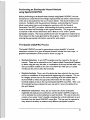
This chapter includes an overview of the Spatial LIQUFAC program, a brief
description of how Spatial LIQUFAC works, and what features are available in
Version 1.0.
•
What is Spatial UQUFAC l
2
•
How does Spatial LIQUFAC work l
2
•
About Spatial UQUFAC Version 1.0
2
What Is Spatial LIQUFAC?
Spatial LIQUFAC is an earthquake hazard analysis system which was developed by
The Georgia Institute of Technology and Tulane University for the U.S. Naval
Facilities Engineering Command. The system operates from within the Geographic
Information System (GIS) software ArcVie'W'!> 3.0 by ESRI, and can predict the
earthquake induced post-liquefaction vertical settlement over a site specific area
using information contained in borehole logs that include Standard Penetration Tests
(SPT).
How does Spatial LIQUFAC Work?
The program LIQUFAC Version 2.00, which performs liquefaction potentiaJ analysis
under earthquake loading and cakulates the vertical settlement at a specific
borehole, was developed for the U. S. Naval Facilities Engineering Command by
Information Dynamics Inc. and Prototype Engineering Inc. in January 199~. Spatial
LIQUFAC is an enhanced version of LIQUFAC 2.00 which can be run from within
the ArcVie""8 3.0 GIS environment.
Spatial LIQUFAC is an environment where the user can easily query the spatial
database of SPT boreholes and geotechnical engineering information for a speciftc
site and prepare appropriate input files for each borehole. These files are then
processed through Spatial LIQUFAC to predict the vertical settlement that will
occur at each borehole location under a speciftc earthquake scenario. These results
are then read back into the GIS environment and a spatial database of the
settlement information is created.
Through Spatial LIQUFAC, the user has the full capabilities of ArcView 3.0, which
include the creation of settlement contours, and the ability to perform spatial
overlays and analysis of the compiled settlement output data.
About Spatial LIQUFAC Version 1.0
Spatial UQUFAC Version 1.0 has been designed and implemented as a site specific
engineering program. Subsequent versions wiU include modifications so that the
program is site independent. The program has been designed to run only for the U.
S. Naval Facility at Treasure Island, California. The software incorporates the use of
the Treasure Island Geotechnical Engineering Database developed by The Georgia
Institute of Technology using data originally compiled by Geomatrix Consultants.
2
CHAPTER
2:
Installation
This chapter includes a list of the system hardware and software required to run
Spatial LIQUFAC, the installation procedure for a personal computer, and a brief
description of how to get started using the Spatial LIQUFAC software.
•
System Requirements
•
ArcView"J 3.0 Requirements
•
Installation Procedure for a Personal Computer
•
Getting Started
s
3
System Requirements
Spatial LJQUFAC Version 1.0 is optimally designed to run on IBM PCs and
compatibles with a Pentium® processor using the Windows '95® operating system.
The program files require about I mb of hard disk space on the "c:" drive. At least
3mb of hard disk space is recommended to accommodate all of the project files that
will be created while using Spatial LIQUFAC. It is recommended that the system
also have at the minimum I6mb of memory (32mb of memory is preferred).
Important:
The Spatial LIQUFAC program files must.be installed into the root
directory on the "c:" drive. Spatial LIQUFAC will not run if these files
are installed anywhere else on the computer.
The screen resolution must be set to I02.f x 768 pixels in order for
Spatial LIQUFAC to run optimally.
ArcViewGD Version 3.0
Spatial UQUFAC is designed to run from within the ArcVie""8 Version 3.0 GIS
environment. It will not run in conjunction with any other GIS package. ArcView®
Version 3.0 for Windows '95 must be installed on the PC. The ArcView8 Extension
Module "Spatial Analyst 1.0 is required for Spatial LIQUFAC to be able to create
contoun of the predicted ground settlements. AU other features of Spatial
LIQUFAC will run without the "Spatial Analyst" installed.
Installation Procedure for a Personal Computer
Perform the following steps to install Spatial LJQUFAC Version 1.0 on your PC:
I. Install ArcVie""8 Version 3.0 GIS software and the "Spatial Analyst 1.0"
extension module on your PC.
2. Insert the Spatial UQUFAC program disk in your 3.S" floppy disk drive.
3. Copy the entire contents of the program disk direct:Jy into the root directory on
your "c:" drive (see system requirements).
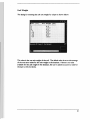
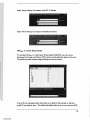
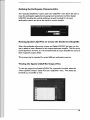
Following a successful installation, the contents of the "arcv_liq" directory should
appear as shown below.
l Hfi•·~ f'.lllP.PY ~F
....... .... ..
·: .~·::-·.·.p_.·~=~ :·~ .:·• _:·, :-·
·-~~--
• . :,1.! _·:•. ·:····.:· :· $·.• l,: ':•·•:.·:····:S.:• l.
· .•L
.•.•.M.·
•·!ll . i•
,·.· ··:·:_
.,· ...•.· •.• _;•: ·.·.· ··:···,··:·.·.:··::· ··::.· :=
_ :_. :·. :· _·:· .:!···: .:: ._: •: ..
. .· .· ·_,,:•. .•:. •.: _::
~~(~1~L
nes:unc : ........... ..
~Jli<J,~ ' :_. ;·:::;::::.::=
::: . .... ...
· ~w. '•'.': · : t •• :: • :::: : : : :.:: : :>H'<: ~: : : , .: ! ;: •::•· ·
'*"li<f;t)Gt:.•.. ·. ::;:,::::::: :·::.:·;:. '. •.:'. ::;· ; ~,:: ; ;; .;:: .::'.:
~ :tif :• : ::::• : : : : ::. ~•· : : : ::::: : •i•::• :: : : :: : i ::: : : :;:: •·· ·
.................. :~- · · : :~ ...· ;~~~;~Hi ~ ~ H ~ ~~ ~;~ ;~i i~~~ ~ F ~ ~: ~ : ...... .
· :.L:~Li ' .:J.;~ : :;s:. ::: · : :_;_; :.~:.~_;_;_;~:~.:_;_;_;.~:.;.:_:~~~;_;_~; : ::
..
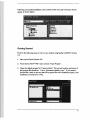
Gettine Started
Perform the following steps to start a new analysis using Spatial LIQUFAC Version
1.0:
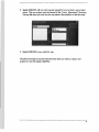
I. Start up ArcView8 Version 3.0.
2. From the ArcView8 "File" menu choose "Open Project".
3. Open the default project for Treasure Island. The correct location and name of
this project file should be: "c:\arcv_liq\treasure\default_ ti.apr". If you cannot
fmd this file, check to be sure that the program files were installed properly (see
installation procedure for a PC).
5
4. Spatial LIQUFAC will now start up and request for you to input a new project
name. This new project must be located in the "c:\arcv_liq\projects\" directory.
Use any ftle name you wish, but do not attach a file extension to the file name.
5. Spatial LIQUFAC is now ready for use.
The above procedure must be followed every time you wish to create a new
project for use with Spatial LIQUFAC.
6
CHAPTER
3: Spatial LIQUFAC Functions
This chapter contains an introduction on performing an earthquake hazard analysis
using Spatial LIQUFAC. The basic operating procedure is discussed and a brief
description is given on each of the functions.
•
Performing an Earthquake Hazard Analysis using Spatial UQUFAC
8
•
The Spatial LIQUFAC Process
8
•
The Spatial LIQUFAC Menu
II
7
Performing an Earthquake Hazard Analysis
using Spatial LIQUFAC
Before perlorming an earthquake hazard analysis using Spatial LIQUFAC, the user
should have a comprehensive knowledge of geotechnical and seismic characteristics
of the site to be analyzed (in this case Treasure Island). This should include at the
minim"m: familiarity with the geotechnical database, understanding the Treasure
Island construction history and stratigraphy, experience with the Standard
Penetration Test (SPT) procedure, understanding the dynamic response of soils
found on the si~ and knowledge of the regional seismicity. This program calculates
an estimate of the vertical deformation that is likely to occur under a specific
. earthquake scenario. The inputs specified by the user throughout an analysis have a
direct impact on the results generated by this program. The user is responsible for
entering the appropriate information required for each analysis.
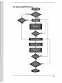
The Spatial LIQUFAC Process
The Spatial LIQUFAC process for generating an output shapefilet of vertical
settlement contours for a given earthquake scenario includes four basic steps. A
graphical representation of this process is shown on page I0.
•
Borehole Selection: A set of SPT boreholes must be created for the site of
interest. These can be selected from the Treasure Island Geotechnical Database
by either using the map, the table, or combination of the map and the table. Any
query procedure available to the user in ArcView9 (ie. table query or spatial
overlay) can be used to select the boreholes.
•
Borehole Analysis: Once a set of boreholes has been selected, the user must
perform a compilation of the geotechnical engineering soil properties. This can
be a lengthy process since it can involve examining all of the available data for
each borehole to select the appropriate information for the analysis. The
borehole analysis produces the required Spatial LIQUFAC input files. After a set
of boreholes has been analyzed, the user may add or remove boreholes from
this set if desired.
•
Settlement Calculation: Next. the user enters the chosen earthquake
magnitude and peak ground acceleration, and the Spatial LIQUFAC program is
run to estimate the vertical settlement at each borehole. This step involves the
creation of an output "point" shapefile containing the vertical settlement at each
borehole from the Spatial LIQUFAC output files. This step may be repeated as
many times as necessary to evaluate many different earthquake scenarios.
8
•
Interpolation and Contouring: Finally, the output "point" shapefiles from the
settlement calculation are used to create contour shapefiles depicting the
earthquake induced post-liquefaction vertical ground settlements for each
earthquake scenario.
Detailed descriptions of the procedures for selecting boreholes, analyzing boreholes,
calculating settlement. and creating contours with Spatial LIQUFAC are provided in
Chapters .., 5, &, and 7 respectively. The user may run the settlement calculation
and contouring routines repeatedly in order to asses many different earthquake
scenarios with the same set of boreholes.
t ArcVie-wf!'J shapefiles are a simple, non-topological format for storing the geometric
location and attribute information of geographic features. The shapefile format
defines the geometry and attributes of geographically-referenced features in as
many as five files with specific file extensions.
9
The Spatial LIQUFAC Process
10
The Spatial LIQUFAC Menu
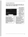
Below is an illustration all of the functions available with Spatial LIQUFAC. The
"LIQUFAC" puU down menu is available through the menu bars associated with
ArcViewe's "project", "view", and "table" windows.
Starts a new analysis
by erasing all info. in
------1 memory
and creating
a new borehole set.
___
Add one or more
_, boreholes to the
active set of analyzed
boreholes.
Remove one or more
boreholes from the
active set of analyzed
boreholes.
Allows user to enter the
earthquake characteristics,
calculate the settlement for the
analyzed boreholes, and create
n output "point" shapefale of
the settlement at each borehole.
Performs the compilation of
eotechnicaJ engineering soil
properties through a user
controlled database query of the
selected set of new boreholes to
create the in ut files.
Creates contour shapefile of the
settlement from the "point"
shapefile.
Allows the user to view and print
the output files created by Spatial
LIQUFAC by opening the files in
Windows '95® notepad.
II
CHAPTER 4: Selecting Boreholes
This chapter explains how to select a new set, or change the active set of boreholes
to be included in the analysis.
•
About the Treasure Island Geotechnical Database
13
•
The Active Set of Analyzed Boreholes
13
•
Selecting a New Set of Boreholes
1'4
•
Adding New Boreholes to the Active Set of Analyzed Boreholes
15
•
Removing Boreholes from the Active Set of Analyzed Boreholes
15
12
About the Treasure Island Geotechnlcal Database
The Treasure Island Geotechnical Engineering Database was originally compiled by
Geomatrix Consultants and subsequently modified by The Georgia Institute of
Technology. The database used in Spatial LIQUFAC Version 1.0 consists of 148
Standard Penetration Test (SPT) boreholes. These SPT boreholes were deemed the
boreholes "most suitable" for geotechnical analysis. Of these I ~8 SPT boreholes, 18
are off-shore boreholes. (The elevation of the top of the borehole is below the
elevation of the water table). The analysis routines integrated in Spatial LIQUFAC
do not have the ability to deal with this condition so off-shore borings cannot be
used in an analysis~
The Active Set of Analyzed Boreholes
The active set of boreholes is made up of boreholes which have been previously
selected and analyzed. A borehole is not added to the active set until it has been
selected and analyzed. The active set of analyzed boreholes in memory is displayed
upon opening a project.
Hint: The user can also view the active set of boreholes by choosing "Add
Boreholes" or "Remove Boreholes" from the "LIQUFAC" menu and then exit
by pressing "Cancel".
The user can change the active set of analyzed boreholes by choosing the ''Select
New Borehole Set", "Add Boreholes", or "Remove Boreholes" options from the
"UQUFAC" Menu.
13
Selecting a New Set of Boreholes
To select a new set of boreholes and restart an analysis, simply select the '~elect
New Borehole Set" option from the LIQUFAC,. menu. This will erase the active
borehole set from memory and set up a new analysis. Once this command is
confirmed the previous boreholes list is lost permanently.
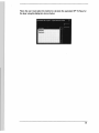
44
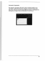
First, Spatial LIQUFAC will prompt the user to enter general information regarding
the project. This information is stored in the header of the Spatial LIQUFAC input
and output files so that previous projects can easily be recognized. The general
information input box is shown below:
Next, the user wiU be asked
set
to
chose a method for selecting the active borehole
Spatial LIQUFAC then opens the appropriate windows and sets up the environment
for selecting boreholes. You are not restricted to simply selecting boreholes with
the mouse. AU available methods for selecting records in ArcView® may be utilized.
Once a set of boreholes is selected, they must be analyzed before the active set is
saved.
14
Addin1 New Boreholes
Use this option to add one or more boreholes to the active set after the initial
boreholes have been analyzed. The procedure for selecting additional boreholes is
identical to that of selecting a new set. While using the "map" or "table" to select
new boreholes, the boreholes which are already part of the active set of analyzed
boreholes will be highlighted in yellow. Once additional boreholes have been
selected, the user must analyze these boreholes before they are saved and added to
the active set of analyzed boreholes.
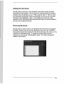
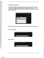
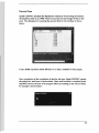
Removing Boreholes
Use this option to remove one or more boreholes from the active set of analyzed
boreholes. Simply choose the "Remove Boreholes" option from the "LIQUFAC"
menu and then select the boreholes from the list of boreholes in the active set. The
revised set is automatically saved. To reinstate boreholes which have been
removed, you must use the "Add Boreholes" option. The "Remove Boreholes"
window is shown below:
IS
CHAPTER
5: Analyzing Boreholes
This chapter explains the details of the compilation of the geotechnicaJ engineering
soil properties.
•
Message Box Display
17
•
Borehole Stratigraphy Input
18
•
Layer Analyses
0 Analysis Required
0
No Analysis Required
19
19
19
20
21
0
0
0
0
0
0
0
•
uses
Unit Weight
SPT N - Values
Dynamic Soil Properties
G/GHAX vs. Cyclic Shear Strain
Volumetric Compression
Percent Fines
Displaying the Minimum Number of Message Boxes
22
2~
25
26
27
28
16
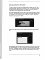
Message Box Display
After the user has confirmed the selection of new borings to be analyzed, there are
two possible methods for compiling the geotechnical engineering soil properties for
the boreholes. The user may choose to view all of the input boxes required to
compile the geotechnical data input or, they may choose to bypass the majority of
input boxes and view the minimum amount of boxes.
For inexperienced users it is recommended that all of the boxes are viewed. If
"No" is selected and most of the boxes are bypassed, refer to the section on
Displaying the Minimum Amount of Message Boxes located at the end of this
chapter.
Borehole Stratigraphy Input
Spatial LIQUFAC reads the available data on stratigraphy from the geotechnical
database and then displays it for the user to confirm. The user may choose to input
different values than what is read from the database. For example, if there are four
{4) layer actually present at a specific location where the database indicates three (3)
layers, the user would specify four (4) layers and enter the appropriate elevations.
Since Spatial LIQUFAC Version 1.0 has been designed to run specifically for
Treasure lslan~ the defaults for stratigraphy have been set to those for Treasure
Island.
First the U$er must select the total number of layers:
17
The Treasure Island default Is three (3) layers: Hydraulic Fill, Young Bay Mud, and
Old Bay Mud. Spatial LIQUFAC will allow for up to five (5) layers.
Next the user must enter the elevation at the top of each layer for this borehole:
To confirm the default selections, press "OK". The elevations are relative
San Francisco Bay Mean Low Low Water (mllw).
to
the
18
Layer Analysis
Next, Spatial LIQUFAC compiles the data for each layer based on the stratigraphy
for the borehole. First, the user must decide if liquefaction and settlement analysis
is to be performed for this layer at this borehole.
Analysis Required
If "Yes" is selected Spatial LIQUFAC proceeds and performs the tasks for layer
analysis outlined in this chapter.
No Analysis Required
If analysis is not required for a layer, liquefaction potential and post-liquefaction
settlement will not be calculated for this layer at this particular borehole. All of the
following user inputs will be skipped and the analysis will proceed to the next layer.
The user may be required to confirm or enter the unit weight for the layer not
requiring analysis. The unit weight is required to cakulate the overburden stress.
At this point Spatial LIQUFAC also checks to see if there are vaJid SPT N-Values
available for the layer at this borehole. The N-VaJues are an essential part of the
liquefaction caJculations and analysis cannot be performed without them. If there
are no N-VaJues available, no analysis is performed for this layer·and the program
proceeds to the next layer.
19
uses
Next, the user Is prompted to select a representative Unifted Soil Classification
System symbol for the soil layer at the borehole. The dialog is shown below:
The USCS symbol is merely used for display purposes in the Spatial LIQUFAC
output file. The value entered here has no effect on the analysis. It may be left
blank or set to "NA" for not available.
20
Unit Weight
The dialog for entering the soil unit weight for a layer Is shown below:
This value is the wet unit weight of the soil. The default value is set to the average
of the non-zero values for the unit weight in the database. If there is no value
available for the unit weight in the database, the user is asked to assume a value for
the layer at this borehole.
21
SPT N-Values
The available SPT N-VaJues for a layer are read automatically from the geotechnical
database. However, Spatial LIQUFAC can only accept up to five (5) SPT N-values
per layer. If there are more than five (5) available N-Values in the geotechnicaJ
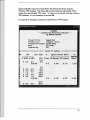
database the following message box will appear.
Pressing "OK" will bring up the next message box which prompts the user to select
between one (I) and f1Ve (5) N-Values for the layer.
-------------------------. .. ... '1 , ::><:< ::H::H:L T.t3HT::H: :::T:;~
::::: ::::: :::::::::::::::::.::::.::.:·::::::::::::::::::::::::::: : ::::::: ::
· · · · ······. ·········· ·· ··· ::: : :::::::::::::::::::;:::
4
....... •·. • 'D
······· .-·.•.• .5••• ·.• . •.::·· · •••,: ·,'_:•.
.1
.·
.•
_:.
:,- . ,
;_:.
'.~
. • •.:.·
.,:
,. •
'.:·:_i.
i, ;• :,: ··· .•. ·.•.
.•
:
~ i - ~:·j. i !ii!:;
1 !j i:
ll. l
: ~ :H:T L H: H : i
·: ti~:'. :·.;.:::.;·.:.:·.i:: : ~ ::·::··::::·:: : : : ::::::
· ~20 ><<<+::: :::a
~ zt : ::::<:::::::::::u: :::1•
.. ..
1
1
!iii !; fli i; !iii
1
I
!i 1 Ii Iii i i ii i It II i Ii i i
11
! Iiii!i
22
Next, the user must select the method to calculate the equivalent SPT N-Value for
the layer using the dialog box shown below:
23
Dynamic Soll Properties
The dynamic properties of the soU layer are an important parameter in calculating
the liquefaction potential and post-liquefaction induced vertical setdement. The
user has four ('4) different methods to input the dynamic soil properties. The dialog
box is shown below.
::~:~:} :ff t ~ '. ~i ~~ : ;I ~; i;:: .· F~~,~~;~ ~~s.
•· F:~~~;~~ft~~~ ··:·•··
: ;iil!iiii ii:iil/ ili t .1111 1:1mi 1:::
......... :·.: ::: ::: : : : :. : . ::::: ·" ' '"
After selecting a method, the user must enter the required values for that method.
Shear Wave Velocity:
Shear Modulus:
2'4
Shear Wave Velocity Correlation with SPT N-Values:
Shear Wave Velocity Correlation with Effective Stress:
G/GMAX vs. Cyclic Shear Strain
To calculate G/GHAX vs. Cyclic Shear Strain Spatial LJQUFAC uses the curves
developed by Vucetic and Dobry ( 1991) which use the plasticity index of the soil.
The plasticity index is input using the dialog box shown below:
A zero (0) can represent either that there is no data for this sample or that the
acutal Pl was equal to zero. The default plasiticity index is set to zero percent (0%).
25
Volumetric Compression
The volumetric compression of the soil in a layer is calculated using the curves
which define a relationship between the volumetric compression and the cyclic
shear strain. There are curves for three (3) different soil types. The dialog box for
selecting which soil type to base the relationship on is shown below:
26
Percent Fines
Spatial LIQUFAC calculates the liquefaction resistance of sand using the method
developed by Seed et al ( 19&4) whkh incorporates the percentage of fines in the
sand. The dialog box for entering the percent fines for the soil layer is shown
below:
A zero (0.00) represents either 0% fines or no data is available for that sample.
Upon completion of the compilation of data for the layer, Spatial LIQUFAC repeats
the analysis for each layer in the borehole. After each borehole is complete Spatial
LIQUFAC informs the user of its progress before proceeding to the next borehole.
An example is shown below:
27
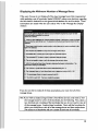
Displaying the Minimum Number of Message Boxes
If the user chooses to not display all of the input message boxes that are generated
while analyzing a set of boreholes, Spatial LIQUFAC makes some decisions regarding
the information obtained from the geotechnicaJ database for each borehole. These
assumptions are stated when the user selects "No" in the "Message Box Display"
window.
. ....................... .... ....... .. ............. .... ....... ... ............ .... ....... ...... ......... . .... . .
···· ·······-··············· ··· ··· ···· ··· ····· .. ..... .... ...... .. .. .
t: · ~~~)1~·~~~ftjf""J"~~~·l~~~~~~.·~~·i¥~Rc>~~t,1·h~~~
~yc;µilfi~: ~· :~• ~ •~~' • ::rtl~•~~.S:tor:~lDP.c>f~~-~.rif~nfrcj'*~ ·····
· ··· · -•:• · · · · · · · · ·: •::· ·····:•·.: :••••~i~··
~· ·~~,y~· ~~~~~~~·~~~~i~~~~~~~~~l~~~~~·fc>ii.)i~··· ·
d~···········
.. · ······- -·· · · ·
~iri~ :tl~• :::
·· ··:
.. ·;··::::: :::: :::.:. ::::· · ... ... .. ... ... ..... .
: . . ............. .................. :· ....••• ;:::: .•:·······:·· .............. ······· ······ · .·:::_ ..... .
I: : : : : : : : : : : : : : : : : : : : : : : : : : : : : : : : : : : : : : : : : : : : : : : : : : : : : : : : : : : : : : : : : : : : : : : : : : : : : : : : : : : : : : : : : : : : : : : : : : : : : : : : : : : '. : •::: : : ~: : : : : : : : : : : : : : : : : : :
~··~~·~~,~~~t:#1~r-~~~~~~~~·~~~l,~~''*1··•••
...· :::: ::: ·<><><>.
. .. .
·~; : ~~ • $fft: . ~1c,~;;•tf6)~~~,~~~~~·~·· · .... .
· ·· :: ::: : :::: :: : :: :: :::: : · .
. ... ... . :: : ::: ;: :: ::: ;::···
..
:; :: :::~ :x:~ :;~~~~:~> ;: :
~-··_ :_:_ l"M
_ _._»:::_:•_' e_··q_·_· ~
.:-.~;: ·_ ._: ·:_ . :·_ ; · :~.·
'j+_:_'.v :'_ ue_J~.··~~
-·. :__· :· ·~-~~~-~--~-· -.·~
_: _m:_· ; ~_·._ :_. ~rB9fi
_.,_ .•
._) ··•••. ... ':;.:: : :•:: ::::::~·.: ;· ::,•·•·•::
............ .
: : : ;: .;: :::::::·· ··
•.
.. ., . . . . .
•e
· 1
.. ..
. .... . - . .... -. . - . . . . .. . .. . .. . . . . .. . . . . . . . . . . . .. . .. : : : : : .. : : : : : : : : : : : : : :: - : : .
....
. . - .... .. --.. . .. . .. . .. .
,, , .,
~:
....
.
~; ·~·
1GJj1~~,~~~~~·1~·~~~· ~
~~Ai:~~~ft>:~~::
•. :--f. :- :~: . · :i. U. :/:tn::•!.·.•:
.. ..
:· · ·
.. .. .. ... .... . ... .. ......
···::·:·:: ::: ::::·: :::: :::·:: ·:: :::·: :: :::::·· :·::: :·::: :: ·:::
:::::::::::::::: :: :::
... .. . .. ..
;:::: :::::: ;. :::::·
:::::::: : :: :::: ::::::: :::: :::::::::::::: :::: :::: :::: ::::::::::::::::::::::: :::: ::::::: ::: :::::::::::: ::: :::: :.:.: :::::::::::::::: :::: ::::::: ::: ::::::::::::: ::: ::::::: ::: ::::::: : ::::: .
. .ri,~i~~~-#~H•·~~:111i:!i-l•!••.:.
~·-~-*~-~-~-~-~~· ~~f~ 1
i\~.: ~·~~- tlf:~~ :~,4¥.~t,~~~·~~~':'.·_::_~_: ~ ·::: ,•: ..!:~:=!:::•l :.·._:.' :_.. ,.,_::_,__•1..:· .::·;[:;::::·,·_;.:•:H!::'•.••::
:::·-:·:··: : : : :· : : :
1•~·- ~H*A3, :i~:~~ i~~~ · ~:~~-r#~~~~~- :
· : : •. . ... ::.::::: : ..::.
If you do not wish to make all of these assumptions, you must view all of the
message boxes.
Hint: If you wish
analyze a large number of boreholes and you only need to view
the message boxes for a few of the boreholes, do the following. First, select a
new borehole set consisting of the boreholes that you do not need to view all
of the message boxes. Analyze these boreholes. Next, add the boreholes for
which you would Uke to view aJI of the message boxes and then analyze them.
The active set of boreholes wiH now consist of both sets of boreholes.
to
28
CHAPTER
6: Calculating Settlement
This chapter explains the how to calculate the liquefaction potential and postliquefaction verticaJ settlement, and create an output point shapefile of the
settlement at each borehole.
•
Defining the Earthquake Characteristics
30
•
Running Spatial UQUFAC to Create the Settlement Shapefile
30
•
Viewing the Spatial LIQUFAC Output Files
30
29
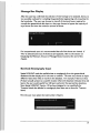
Defining the Earthquake Characteristics
The "Caclulate Settlement" option under the "LIQUFACt menu allows the user to
input the earthquake magnitude and peak ground acceleration and then Spatial
LIQUFAC calculates the vertical settlement at each borehole for the input
earthquake scenario and stores the results in a point shapefile.
Running Spatial LIQUFAC to Create the Settlement Shapefile
After, the earthquake information is input, and Spatial LIQUFAC has been run, the
user is asked to input a filename for the output settlement shapefile. This file can be
stored anywhere, however, it is recommended that all output shapefiles be stored in
their respective projects folder.
This process may be repeated for several different earthquake scenarios.
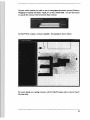
Viewing the Spatial LIQUFAC Output Files
To view the output from Spatial LIQUFAC for a particular borehole, select the
"View LIQUFAC Output" option from the "LIQUFAC" menu. Then select the
borehole you would like to view.
30
Spatial LIQUFAC opeM the output file for the selected borehole using the
Windows '95• Notepad. The output flle may be printed by selecting the "Print"
option from the Notepad "File" menu. To return to ArcVie..,,,e, close the Windows
'95® Notepad. It is not necessary to save the ftle.
An example of viewing the output file using Windows '95® Notepad:
31
CHAPTER
7: Creating Contours
This chapter explains the how to create a contour shapefile of the vertical
settlement from the point shapefile generated by Spatial LIQUFAC.
•
Creating Contours of the Vertical Settlement
33 .
32
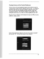
Creating Contours of the Vertical Settlement
To draw contours of the post-liquefaction induced vertical settlement, select the
"Create Contours" option from the "LIQUFAC'• pull down menu. You will then be
prompted to select the name of the point shapefile to create the contours from.
This is one of the output point shapefiles that Spatial LIQUFAC created while
calculating the settlement. There should be a different output shapefile for each
earthquake scenario that you ran. Select one of these shapefiles and press "OK".
Next, the "Contours" dialog box will be displayed showing several different options
. available for creating contours:
Set the Output Grid Extent to "Same As <the name of the settlement shapefile>"
and then press "OK". ArcView8 then displays the next dialog box:
33
Choose which method you wish to use to interpolate the surface (Inverse Distance
Weighted or Spline) and select "settle_ln" as the Z Value Reid. You are then asked
to specify the contour intervaJ and the base contour.
ArcVie-w8 then creates a contour shapefile. An example is shown below:
For more details on creating contours with ArcView8, please refer to the ArcView@
On-Une help.
3-4
CHAPTER 8: Sample Run
This chapter shows the input and output of an sample run that was performed for
Treasure Island using Spatial LIQUFAC.
•
Description of Analysis
36
•
Borehole Selection
36
•
Borehole Analysis
37
•
Results
38
35
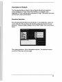
Description of Analysis
The foUowing describes an analysis of the earthquake induced post-liquefaction
vertical settlement at Treasure Island Naval Facility for a earthquake with a
magnitude of 7.0 and a peak ground acceleration of 0.16 gs. The analysis will include
all of the above water level boreholes.
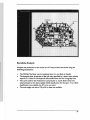
Borehole Selection
First, the appropriate boreholes must be selected. To accomplish this, a query was
used to select au of the boreholes with elevations greater than the ground water
elevations~ The query builder available in the ArcView8 "Table" menu used is shown
below:
... ..... . .......
·· · ············ ·- ··· ·· ··· ··· ·······
·:; ::;:::: :::::: ::::: :: :::::::: ::: :::::::: :: ::
::;·1!·rn.f t: i!·::.:::1:rn:1ii:~:.:·1@. ~;: _;:~
·1 -:
....
The resulting selection is 130 of 148 available boreholes. The selected boreholes
are shown on the map on the next page.
36
Borehole Analysis
Analysis was performed on the active set of Treasure Island boreholes using the
following assumptions:
•
•
•
•
The Old Bay Mud layer was not analyzed since it is not likely to liquefy.
The dynamic shear properties of the soil were specified by a shear wave velocity
equal to S 11 ft/sec for the hydraulic fill and 603 ft/sec for the Young Bay Mud.
The curve used for the Volumetric Compression vs. Cyclic Shear Strain was
selected based on the best available uses classification for the layer. If no uses
classification was available, the SP curve was used.
The unit weight was set to 120 pcf if no data was available.
37
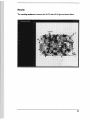
Results
The resulting settlement contours for M=7.0 and a=0.16 (s are shown below.
38
APPENDIX A: Database Legend
Below are two tables which describe some of the symbols and abbreviations used in
the geotecnical database.
Symbol
Consultant Name
I
l
PAL Consult.ants
Woodward-Clyde Consultants
3
4
Harding Lawson Associates
Rutherford & Chekene
s
'
7
8
9
10
11
12
13
Symbol
AUG
RT.WS
WS.BR
McCreary-Koretsky Engineers
GEO/Engineering Consultants
Tejima and Associates
Geo/Resource Consultants
Associated Geotechnical Engineer:s
Terratech lnc.
Taber Consultants
Harlan MiUer Tait Consultants
Geomatrbc Inc.
Drill Method
Auger
Rotary Wash
Wash Boring
39
APPENDIX
B:
References
Vucetic, M. and Dobry, R. ( 1991) "Effect of Soil Plasticity on Cyclic Response",
Journal of Geotechnical Engineering, Vol 117, No. I.
Seec:L H. B.~ Tokimatsu, K., Harder, L F., and Chung, R. M. ( 19&4) The Influence of
SPT Procedures in Soil Liquefaction Resistance E.voluation, Report No. UBC/EERC-&4/ I 5,
Earthquake Engineering Research Center, University of California, Berkeley, CA