1
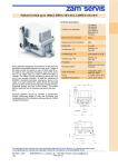
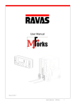
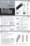
The right choice in sensors
Conveyor belt operation can be divided into two areas
according to the definition of the environment the so-called
“heavy duty” and “light duty”. This designation applies only
to the simpler division of the sensors mentioned below. The
exact environment specifications must be known prior to
selecting the sensors. Frequently it can be found in the
project documentation or in the auditor's report. If you do
not have this classification or if it does not comply with the
new standards, it must be made prior to realizing the project
documentation for automation.
RDP 444 Automation Unit
Description:
Aberration sensors
Heavy
duty
Light
duty
Sensor VSP-3B
A
A
Sensor LHPE-10/2-LP
Sensor ET-4T
A
N
Z
A
Heavy
duty
Light
duty
Switch LHPEw-10/2-B-S
A
Z
Switch LHPEw-10/2-BSL-S
A
Z
Switch LHPEw-10/2-BSR-S
Switch SNS 12
Switch Lifeline 4
A
N
N
Z
A
A
Sensor type
Pull-wire switches
Heavy duty
It is a characteristic for the outdoor environment with
climatic influences where heavy material is produced and
transported and where heavy machinery is used. The
technology in such duty is continuously subject to damages
caused by the material being transported or by machine
manipulation, by dust or mud, by temperature changes,
and by the sturdiness of the whole technology designed for
the relevant environment. “Heavy duty” can mean all
logging systems, manufacturing technologies for mineral
raw materials, etc.
Light duty
It is a designation for operation at constant temperature
inside factory buildings, where light material is transported
using small conveyors. Brute force is not necessary here
and environmental characteristics low dust nuisance,
cleanness, etc. will guarantee long service life of the
technology. Conveyor production in car factories and
electronics factories, production of plastic moldings etc.
can be considered “light duty”.
Typ spínaèe
Glossary:
A - we recommend for this application excellent solution
M -possible to use for this application, but all parameters
must be checked
N- not suitable, will not work under given conditions,
definitely short service life
Z- will work reliably, but this solution is unnecessarily
expensive
The automation unit controls one conveyor belt drive by
means of a control network. It is designed to ensure its wide
application possibilities for different drives. Its modular
design enables quick compiling with regard to the given
drive power.
The control unit has terminals for connecting the necessary
sensors including inputs for technology measurement.
Safe start and stop of the system will be achieved by proper
sensor mounting on the conveyor belt and by connecting to
the relevant terminals according to the manual. The control
logic and the status control are programmed in the control
system which can recognize the connected sensors and
determine the trace mode. This unit can run in an
autonomous mode without the control network.
All status and starting records are made automatically and
can be listed on site by means of a computer. The unit is
adapted for relay operation and control as well. It means
that it can be inserted in the middle of the conveyor line and
start and/or stop commands can be performed from the
contactor room by means of relay contacts.
This possibility serves for the gradual recovery of the
conveyor system without a radical disturbance or blocking
of the transport. Total investment can be spread over a
longer time period.
The unit is comprised of a control unit MODUL IQ and a
power part MODUL SJW. Both parts are designed as one
distribution field and they are delivered in a distribution
board with high protection as standard equipment. The
distribution board can be delivered with more units as an
economical solution. This version can be used where
conveyors are close to each other.
All conveyor status information from the sensors is brought
to the control part. The safety loop directly controls the
power part and it will transmit the information about
emergency stopping to the control unit as well. The control
unit will provide this command for other devices and will
inform the operating staff by means of the control network.
The power supply is provided by two cable ducts. The
power supply for the drive can be the often used 3 x
500V/50Hz and the power supply for the control
230V/50Hz, preferably with a back-up power supply.
Double feeding will increase the quality of control in terms
of disturbance and it will enable better system check (line
operation can be simulated without unnecessary starting
of the drives).
Rpm sensors
Heavy
duty
Light
duty
Sensor SHR 2, magnet MHR 2
A
Z
Sensor SHR 3, magnet MHR 2
Sensor XSA11373, magnet MHR 2
Sensor XSA12373, magnet MHR 2
M
N
Z
A
N
A
Heavy
duty
Light
duty
Sensor type
Transfer sensors
Sensor type
Sensor RHP 5
A
N
Sensor UMV1
Sensor UMV2
Sensor K1 BOS-21, probe BOS-4T
A
A
A
A
N
A
The catalogue sheet contains only some parameters important for your decision. For planning always require
a corresponding user manual and eventually a technical consultation on the possibilities of use.
ISO 9001 : 2001
V01
ZAM-SERVIS, s.r.o. Ostrava, tel.: +420 596 135 422, email: [email protected]
www.zam.cz
ISO 9001 : 2001
V01
ZAM-SERVIS, s.r.o. Ostrava, tel.: +420 596 135 422, email: [email protected]
www.zam.cz
RDP 444 Automation Unit
Software control of the conveyor paths
Description:
The RDP 444 automation unit is programmed by means of
the SWRDP 444 utility program or by means of
visualization software with a specific programmed
application.
The SWRDP 444 program
This program is designed for an automation unit engaged
in the system without visualization software. Configuration
of the unit, parameters for input data from the sensors, and
control methods (outputs), where dependences on other
units within the network are defined, can be adjusted here.
It is also possible to read the archived unit status data from
the control part. This software is not intended for line
control and cannot be used for this purpose.
The lines (units) are started by means of the voltage input
at the terminals for the “start” command and by
disconnecting from the command input for the “stop”
command. If more units are linked in a network, the “start”
or “stop” commands will be transferred to the other RDP
444 units after time constants and modes are defined.
Information about emergency stopping or stopping for
other reasons (e.g. slipping) is transferred within the
network between the units as well. Information about
conveyor run and/or breakdown is available at the dry
output contact terminals which can then be used for the
control of the continuing conveyor path without RDP 444
control.
The figure above shows the schematic diagram for an
optimum connection of the RDP 444 unit. The most suitable
position of the unit is close to the conveyor drive. The
position is determined by the cabling for the drive. The
sensors are connected according to the diagram; the
longest path is that of the rpm sensor which will be installed
on the angle pulley. If the drive is on the opposite side of the
conveyor than in the diagram, the transfer sensor will
represent the same distance.
ISO 9001 : 2001
V01
This situation is usually solved by one cable. The pull-wire
system and the aberration sensors will be adapted
according to the specific situation. All cabling is positioned
with reference to disturbance safety and theft protection.
The automation unit is delivered for one drive in one
distribution board. For conveyor combinations with drives
close to eachother the automation unit will be located on
one distribution board.
ZAM-SERVIS, s.r.o. Ostrava, tel.: +420 596 135 422, email: [email protected]
www.zam.cz
pre-programmed procedures if any crash should occur. For
example it can switch off the path with material before the
crash point and it will leave the path after this point to
transport the remaining material. The intervention can be
performed manually by the operating staff by means of
controls. This example does not show emergency stop!
In addition to conveyor path and machine technology
control, the program will make an automatic back up of all
operations executed and it will archive information about
conveyor or other technology conditions from the individual
RDP 444 units. This data can be used for statistical
calculations of the number of faults, their types (e.g.
slipping), time they happened, etc. These calculations can
serve as a basis for subsequent measures against similar
faults.
Visualization software
Visualization software is used for control and regulation of
the whole technology. The most suitable program for
visualization is Control Web. However, we are able to carry
out visualization in other programs if required.
Visualization means graphic representation of the
technology, where important machine parts status data are
shown. They are standardly displayed as simple drawn
objects. In addition to that, 3D animation or film sections
are available for better lucidity. In the visualization, active
buttons designed to control the technology or to display
details of the individual parts are used.
The visualization software is installed in the standard or the
industrial computer. The computer is connected to the
RDP 444 automation unit network and to the control
system network for other technologies (sieve control,
trouser slippage, etc.) through a module with a converter.
Primary configuration of the unit and of the parameters for
input information from the sensors is made through this
connection. Its control is defined in the relevant
visualization application and therefore it is not necessary
to enter these parameters. The start and stop commands
are given through the network from the computer. The
program can instantly check the conveyor condition and it
will display the location of the fault and intervene
automatically according to
ISO 9001 : 2001
V01
ZAM-SERVIS, s.r.o. Ostrava, tel.: +420 596 135 422, email: [email protected]
www.zam.cz