1
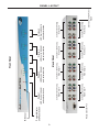
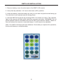
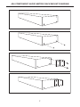
4x4 Component
Audio Matrix
USER
MANUAL
www.gefen.com
ASKING FOR ASSISTANCE
Technical Support:
Telephone
(818) 772-9100
(800) 545-6900
Fax
(818) 772-9120
Technical Support Hours:
8:00 AM to 5:00 PM Monday through Friday.
Write To:
Gefen Inc.
C/O Customer Service
20600 Nordhoff St.
Chatsworth, CA 91311
www.gefen.com
[email protected]
Notice
Gefen Inc. reserves the right to make changes in the hardware, packaging and any
accompanying documentation without prior written notice.
The 4x4 Component Audio Matrix is a trademark of Gefen Inc.
© 2007 Gefen Inc., All Rights Reserved
TABLE OF CONTENTS
1
Introduction / Operation Notes
2
Features
3
Panel Layout
4
Using the 4x4 Component Audio Matrix
5
RMT16-IR Installation
6
RS-232 Interface
7
4x4 Component Audio Matrix Rack Mount Diagram
8
Specifications
9
Terminology
10
Warranty
INTRODUCTION
Thank you for purchasing the 4x4 Component Audio Matrix.
The 4x4 Component Audio Matrix switches four component video with analog audio
sources to any four component with analog audio displays.
The 4x4 Component Audio Matrix switcher has four component video with analog audio
inputs and four component with analog audio outputs. There are 4 component video
( 3 RCA) with analog audio ( 2 RCA) inputs and 4 component ( 3 RCA) with analog
audio ( 2 RCA) outputs.
Note: The switching is done by using either the RMT-16-IR remote control or through
the RS232 port. The 4x4 Component Audio Matrix is rack mountable.
OPERATION NOTES
READ THESE NOTES BEFORE INSTALLING
OR OPERATING THE 4X4 COMPONENT AUDIO MATRIX
• The 4x4 Component Audio Matrix is housed in a metal box for better RF shielding.
• The 4x4 Component Audio Matrix works with all component displays
1
FEATURES
Features
• Allows any component display to view any source at any time
• Allows any source to be displayed on multiple displays at the same time
• Maintains highest video resolution up to 1080p
• Each display's inputs can be switched with the IR remote control, front panel push
buttons, or through RS232
Includes:
(1) 4x4 Component Audio Matrix
(4) 5 RCA Cables (M-M)
(1) 12VDC 5A Power Supply
(1) User Manual
(1) RMT-16IR Remote Control
(1) Rack Ears
2
RS232 Controller Port
Power Indicator
and Reset button
IR Sensor
3
Display 3
LED source Indicator
and selector button
Component and Analog
Audio Output 1
Component and Analog
Audio Output 2
Component and Analog
Audio Output 4
Component and Analog
Audio Input 4
Component and Analog
Audio input 3
Back Panel
Display 2
LED Source Indicator
and selector button
Component and Analog
Audio Output 3
Display 1
LED Source Indicator
and selector button
Front Panel
Connects to 12VDC Power
Supply
Component and Analog
Audio Input 2
Component and Analog
Audio Input 1
Display 4
LED Source Indicator
and selector button
PANEL LAYOUT
USING THE 4X4 COMPONENT AUDIO MATRIX
1
Connect all the sources to the component and analog audio inputs on the 4x4
Component Audio Matrix using the supplied cables.
2
Connect the component with audio displays to the outputs on the 4x4
Component Audio Matrix.
3
Connect the 12VDC power supply to the 4x4 Component Audio Matrix
4
Use the push buttons for each display on the front of the unit to select the
source for that display.
5
Controlling the 4x4 Component Audio Matrix using the RMT16-IR:
Pressing Buttons...
1-4
5-8
9-12
13-16
Switches...
Display 1 to view Source 1, 2, 3, or 4
Display 2 to view Source 1, 2, 3, or 4
Display 3 to view Source 1, 2, 3, or 4
Display 4 to view Source 1, 2, 3, or 4
4
RMT16-IR INSTALLATION
1. Remove battery cover from the back of the RMT16-IR remote.
2. Verify that dip switches 1 & 2 are in the down (OFF) position.
3. Insert the battery, hold the battery so that you can see the positive side facing up.
The side that is not marked must be facing down.
4. Test the RMT16-IR remote by pressing ONLY one button at a time. The indicator
light on the remote will flash once each time you press a button. WARNING: Do not
press multiple buttons simultaneously and do NOT press buttons rapidly. These actions will cause the remote to reset and steps 1-4 will have to be repeated.
Note: The RMT16-IR ships with two batteries. One battery is required for operation,
the second battery is complimentary.
5
RS-232 INTERFACE
Binary Table
ASCII Corresponding
RMT16-IR
Button
1
1
2
2
3
3
4
4
5
5
6
6
7
7
8
8
Binary
ASCII
0011 0001
0011 0010
0011 0011
0011 0100
0011 0101
0011 0110
0011 0111
0011 1000
9
a
b
c
d
e
f
g
Corresponding
RMT16-IR
Button
9
10
11
12
13
14
15
16
Binary
0011 1001
0110 0001
0110 0010
0110 0011
0110 0100
0110 0101
0110 0110
0110 0111
RS232 Settings
Bits per second ................................................................................................. 19200
Data bits .................................................................................................................... 8
Parity .................................................................................................................. None
Stop bits .....................................................................................................................1
Flow Control ....................................................................................................... None
6
4X4 COMPONENT AUDIO MATRIX RACK MOUNT DIAGRAM
7
SPECIFICATIONS
Input ............................................... YPbPr x 4 or RGsB x 4 (or RGBHV) 1 Vp-p@ 75
ohm
Output ............................................................... YPbPr x 4, or RGsB (or RGBHV) x 4
Analog audio input/output ............................................... Audio 2 Vrms max 47k ohm
Bandwidth ........................................................................................... 480MHz (-3dB)
Video Range ..................................................................................................... 1080p
Differential gain ................................................................................................. 0.05%
Differential phase ..................................................................................... 0.05 degree
Power Supply ...................................................................................... 12V DC 5 Amp
Dimensions ................................................................... 17.25” W x 1.75” H x 4.95” D
Shipping Weight ............................................................................................... 10 lbs.
8
TERMINOLOGY
DDC
Short form for Display Data Channel. It is a VESA standard for communication between a monitor
and a video adapter. Using DDC, a monitor can inform the video card about its properties,
such as maximum resolution and color depth. The video card can then use this information to
ensure that the user is presented with valid options for configuring the display.
DDWG
Digital Display Working Group DDWG are the creators of the DVI specification.
DVI
Digital Visual Interface. Connection standard developed by Intel for connecting computers to
digital monitors such as flat panels and DLP projectors. A consumer electronics version, not
necessarily compatible with the PC version, is used as a connection standard for HDTV tuners
and displays. Transmits an uncompressed digital signal to the display. The latter version uses
HDCP copy protection to prevent unauthorized copying.
HDCP
High-Bandwidth Digital Content Protection. Created by Intel, HDCP is used with HDTV signals
over DVI and HDMI connections and on D-Theater D-VHS recordings to prevent unauthorized
duplication of copy written material.
HDMI
The High-Definition Multi-media Interface (HDMI) is an industry-supported, uncompressed,
all-digital audio/video interface. HDMI provides an interface between any compatible digital
audio/video source, such as a set-top box, DVD player, and A/V receiver and a compatible
digital audio and/or video monitor, such as a digital television (DTV).
HDTV
High-Definition Television. The high-resolution subset of our DTV system. The ATSC defines
HDTV as a 16:9 image with twice the horizontal and vertical resolution of our existing system,
accompanied by 5.1 channels of Dolby Digital audio. The CEA defines HDTV as an image
with 720 progressive or 1080 interlaced active (top to bottom) scan lines. 1280:720p and
1920:1080i are typically accepted as high-definition scan rates.
RS-232
Recommended Standard 232. This is the de facto standard for communication through PC
serial ports. It can refer to cables and ports that support the RS232 standard.
VESA
Video Electronic Standards Association, a consortium of manufacturers formed to establish
and maintain industry wide standards for video cards and monitors. VESA was instrumental in
the introduction of the Super VGA and Extended VGA video graphics standards with a refresh
rate of 70 Hz, minimizing flicker and helping to reduce user eyestrain and fatigue.
9