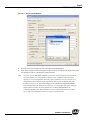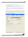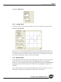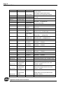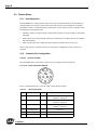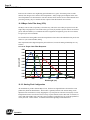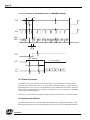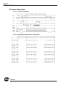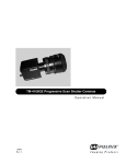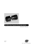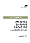
1
TM/TMC/RM/RMC-2040GE Progressive Scan Cameras Operation Manual 10447Rev. B See the Possibilities Page ii Page iii Notice The material contained in this manual consists of information that is proprietary to JAI Inc., and may only be used by the purchasers of the product. JAI Inc. makes no warranty for the use of its product and assumes no responsibility for any errors which may appear or for damages resulting from the use of the information contained herein. JAI Inc. reserves the right to make changes without notice. Microsoft, Windows XP, Windows 2000, Windows 98, Windows NT, and Windows Explorer are either registered trademarks or trademarks of Microsoft Corporation in the United States and/or other countries. Warranty For information about the warranty, please contact your factory representative. Certifications CE Compliance The TM-2040GE camera has been certified to conform to the requirements of Council Directive 89/336/EC for electromagnetic compatibility and to comply with the following European Standards: Immunity: Emissions: EN 55024: 1998 + A1: 2001 + A2: 2003 EN 55022: 1998 + A1: 2000 + A2: 2003 All JAI Inc. products bearing the CE mark have been declared to be in conformance with the applicable EEC Council Directives. However, certain factory-installed options or customer-requested modifications may compromise electromagnetic compatibility and affect CE compliance. Please note that the use of interconnect cables that are not properly grounded and shielded may affect CE compliance. Contact JAI Inc. Applications Engineering Department for further information regarding CE compliance. FCC This equipment has been tested and found to comply with the limits for a Class A digital device, pursuant to Part 15 of the FCC Rules. These limits are designed to provide reasonable protection against harmful interference when the equipment is operated in a commercial environment. This equipment generates, uses and can radiate radio frequency energy and, if not installed and used in accordance with the instruction manual, may cause harmful interference to radio communications. Operation of this equipment in a residential area may cause harmful interference, in which case the user will be required to correct the interference at his own expense. WARNING UL ® ST I A SS O CIA TI ON RM FILE # A3942 REG MEMBER FI TED IM MA O NG GI A AU T Changes or modifications to this unit not expressly approved by the party responsible for FCC compliance could void the user’s authority to operate the equipment. ERED JAI, INC. ISO-9001 RM-2040GE / RMC-2040GE Supplement This applies to cameras in this manual that are RoHS compliant,which are noted by RM or RMC. The following statement is related to the regulation on “ Measures for the Administration of the control of Pollution by Electronic Information Products “ , known as “ China RoHS “. The table shows contained Hazardous Substances in this camera. mark shows that the environment-friendly use period of contained Hazardous Substances is 15 years. 嶷勣廣吭並㍻ 嗤蕎嗤墾麗嵎賜圷殆兆各式根楚燕 功象嶄鯖繁酎慌才忽佚連恢匍何〆窮徨佚連恢瞳麟半陣崙砿尖一隈〇云恢瞳ゞ 嗤蕎嗤 墾麗嵎賜圷殆兆各式根楚燕 〃泌和 桟隠聞喘豚㍉ 窮徨佚連恢瞳嶄根嗤議嗤蕎嗤墾麗嵎賜圷殆壓屎械聞喘議訳周和音氏窟伏翌 亶賜融延、窮徨佚連恢瞳喘薩聞喘乎窮徨佚連恢瞳音氏斤桟廠夛撹冢嶷麟半 賜斤児繁附、夏恢夛撹冢嶷鱒墾議豚㍉。 方忖仝15々葎豚㍉15定。 Page iv TM-2040GE Series Operation Manual JAI Inc. 625 River Oaks Parkway San Jose, CA 95134 Tel:(408) 383-0300 Tel:(800) 445-5444 Fax:(408) 383-0301 E-mail: [email protected] www.jai.com Page v Table of Contents Table of Contents . . . . . . . . . . . . . . . . . . . . . . . . . . . . . . . . . . . . . . . . . . v List of Figures. . . . . . . . . . . . . . . . . . . . . . . . . . . . . . . . . . . . . . . . . . . . ix List of Tables . . . . . . . . . . . . . . . . . . . . . . . . . . . . . . . . . . . . . . . . . . . . xi 1 Software Introduction 1.1 1.2 1.3 1.4 ................................1 Scope of the Document . . . . . . . . . . . . . . . . . . . . . . . . . . . . . . . . . . . 1 Related Documents . . . . . . . . . . . . . . . . . . . . . . . . . . . . . . . . . . . . . . . 1 Gigabit Ethernet Camera Interface . . . . . . . . . . . . . . . . . . . . . . . . . . . 2 Software Installation . . . . . . . . . . . . . . . . . . . . . . . . . . . . . . . . . . . . . . 2 1.4.1 1.4.2 1.4.3 1.4.4 Before Installing the GigE Series Camera-SDK Software . . . . . . . . . . . . . . . 2 Installing the Software . . . . . . . . . . . . . . . . . . . . . . . . . . . . . . . . . . . . . . . . . . 2 Uninstalling the Software . . . . . . . . . . . . . . . . . . . . . . . . . . . . . . . . . . . . . . . . 3 Quick-Start . . . . . . . . . . . . . . . . . . . . . . . . . . . . . . . . . . . . . . . . . . . . . . . . . . . 4 2 Connectors ........................................6 2.1 Power and Signals Connector . . . . . . . . . . . . . . . . . . . . . . . . . . . . . . . 6 2.2 Ethernet . . . . . . . . . . . . . . . . . . . . . . . . . . . . . . . . . . . . . . . . . . . . . . . . 7 3 Configuring the TM-2040GE Camera ...................8 3.1 Setup . . . . . . . . . . . . . . . . . . . . . . . . . . . . . . . . . . . . . . . . . . . . . . . . . . 8 3.2 Configuring the Imager . . . . . . . . . . . . . . . . . . . . . . . . . . . . . . . . . . 10 3.2.1 GUI Features . . . . . . . . . . . . . . . . . . . . . . . . . . . . . . . . . . . . . . . . . . . . . . . . . 11 3.3 Configuring the Internal Frame Grabber . . . . . . . . . . . . . . . . . . . . . 11 3.4 Modes . . . . . . . . . . . . . . . . . . . . . . . . . . . . . . . . . . . . . . . . . . . . . . . . 11 3.4.1 Check the Current Camera Setting . . . . . . . . . . . . . . . . . . . . . . . . . . . . . . . . 11 3.4.2 Exposure Control . . . . . . . . . . . . . . . . . . . . . . . . . . . . . . . . . . . . . . . . . . . . . 12 3.4.3 Scan Mode . . . . . . . . . . . . . . . . . . . . . . . . . . . . . . . . . . . . . . . . . . . . . . . . . . 14 3.4.4 Programmable Scan . . . . . . . . . . . . . . . . . . . . . . . . . . . . . . . . . . . . . . . . . . . 14 3.4.5 User Programmable Variable Partial Scan . . . . . . . . . . . . . . . . . . . . . . . . . . 14 3.4.6 Gain Settings . . . . . . . . . . . . . . . . . . . . . . . . . . . . . . . . . . . . . . . . . . . . . . . . . 16 3.4.7 The Gain . . . . . . . . . . . . . . . . . . . . . . . . . . . . . . . . . . . . . . . . . . . . . . . . . . . . 16 3.4.8 Look-Up Table . . . . . . . . . . . . . . . . . . . . . . . . . . . . . . . . . . . . . . . . . . . . . . . 17 3.4.9 Memory Pages . . . . . . . . . . . . . . . . . . . . . . . . . . . . . . . . . . . . . . . . . . . . . . . 17 3.4.10 Free-Running Mode . . . . . . . . . . . . . . . . . . . . . . . . . . . . . . . . . . . . . . . . . . . 18 3.4.11 Externally Triggered . . . . . . . . . . . . . . . . . . . . . . . . . . . . . . . . . . . . . . . . . . . 18 3.4.12 Internally Triggered . . . . . . . . . . . . . . . . . . . . . . . . . . . . . . . . . . . . . . . . . . . 18 3.4.13 Save/Restore Settings to Your Hard Disk . . . . . . . . . . . . . . . . . . . . . . . . . . . 19 3.4.14 White Balance Control (Color Versions Only) . . . . . . . . . . . . . . . . . . . . . . . 19 3.4.15 Main Menu: “Option” . . . . . . . . . . . . . . . . . . . . . . . . . . . . . . . . . . . . . . . . . . 20 3.4.16 Version . . . . . . . . . . . . . . . . . . . . . . . . . . . . . . . . . . . . . . . . . . . . . . . . . . . . . 20 3.4.17 Exit . . . . . . . . . . . . . . . . . . . . . . . . . . . . . . . . . . . . . . . . . . . . . . . . . . . . . . . . 20 4 Signal Handling . . . . . . . . . . . . . . . . . . . . . . . . . . . . . . . . . . . 21 4.1 Camera Inputs . . . . . . . . . . . . . . . . . . . . . . . . . . . . . . . . . . . . . . . . . . 21 4.2 Camera Outputs . . . . . . . . . . . . . . . . . . . . . . . . . . . . . . . . . . . . . . . . 21 4.3 GPIO Control Block . . . . . . . . . . . . . . . . . . . . . . . . . . . . . . . . . . . . . 21 Table of Contents Page vi 4.4 GPIO Label Table . . . . . . . . . . . . . . . . . . . . . . . . . . . . . . . . . . . . . . . 24 4.5 Pulse Generators . . . . . . . . . . . . . . . . . . . . . . . . . . . . . . . . . . . . . . . . 25 5 GigE Series Camera Serial Commands 6 Introduction . . . . . . . . . . . . . . . . . 27 . . . . . . . . . . . . . . . . . . . . . . . . . . . . . . . . . . . . . . 31 6.1 Software Installation . . . . . . . . . . . . . . . . . . . . . . . . . . . . . . . . . . . . 32 6.1.1 Before Installing Dual-Tap AccuPiXEL Series Camera-Control Software . 32 6.1.2 Installing the Software . . . . . . . . . . . . . . . . . . . . . . . . . . . . . . . . . . . . . . . . . 32 6.1.3 Uninstalling the Software . . . . . . . . . . . . . . . . . . . . . . . . . . . . . . . . . . . . . . . 33 6.2 TM/TMC/RM/RMC-2040GE Camera . . . . . . . . . . . . . . . . . . . . . . . 34 6.3 Using the GigE mode . . . . . . . . . . . . . . . . . . . . . . . . . . . . . . . . . . . . 34 7 GUI Features . . . . . . . . . . . . . . . . . . . . . . . . . . . . . . . . . . . . . 35 7.1 Operating The Control Software 7.1.1 7.1.2 7.1.3 7.1.4 7.1.5 7.1.6 7.1.7 . . . . . . . . . . . . . . . . . . . . . . . . . . . 36 Exposure Control . . . . . . . . . . . . . . . . . . . . . . . . . . . . . . . . . . . . . . . . . . . . . 36 Gain Control . . . . . . . . . . . . . . . . . . . . . . . . . . . . . . . . . . . . . . . . . . . . . . . . . 38 Offset Voltage . . . . . . . . . . . . . . . . . . . . . . . . . . . . . . . . . . . . . . . . . . . . . . . . 39 Video Depth . . . . . . . . . . . . . . . . . . . . . . . . . . . . . . . . . . . . . . . . . . . . . . . . . 40 LUT (Look-Up Table) . . . . . . . . . . . . . . . . . . . . . . . . . . . . . . . . . . . . . . . . . 40 Main Menu: “Option” . . . . . . . . . . . . . . . . . . . . . . . . . . . . . . . . . . . . . . . . . . 42 EEPROM . . . . . . . . . . . . . . . . . . . . . . . . . . . . . . . . . . . . . . . . . . . . . . . . . . . 42 8 Hardware Introduction . . . . . . . . . . . . . . . . . . . . . . . . . . . . . . 45 8.1 Product Description . . . . . . . . . . . . . . . . . . . . . . . . . . . . . . . . . . . . . 45 8.2 Features . . . . . . . . . . . . . . . . . . . . . . . . . . . . . . . . . . . . . . . . . . . . . . 46 9 Installation . . . . . . . . . . . . . . . . . . . . . . . . . . . . . . . . . . . . . . . 47 9.1 Getting Started . . . . . . . . . . . . . . . . . . . . . . . . . . . . . . . . . . . . . . . . . 47 9.1.1 Unpacking Instructions . . . . . . . . . . . . . . . . . . . . . . . . . . . . . . . . . . . . . . . . . 47 9.1.2 Components . . . . . . . . . . . . . . . . . . . . . . . . . . . . . . . . . . . . . . . . . . . . . . . . . 47 9.1.3 Accessories and Options . . . . . . . . . . . . . . . . . . . . . . . . . . . . . . . . . . . . . . . . 47 9.2 Camera Setup 9.2.1 9.2.2 9.2.3 9.2.4 9.2.5 . . . . . . . . . . . . . . . . . . . . . . . . . . . . . . . . . . . . . . . . . . 48 Heat Dissipation . . . . . . . . . . . . . . . . . . . . . . . . . . . . . . . . . . . . . . . . . . . . . . 48 Connector Pin Configurations . . . . . . . . . . . . . . . . . . . . . . . . . . . . . . . . . . . 48 Power Supplies and Power Cable Setup . . . . . . . . . . . . . . . . . . . . . . . . . . . . 49 Attaching the Camera Lens . . . . . . . . . . . . . . . . . . . . . . . . . . . . . . . . . . . . . 51 Adjustable Back-Focus . . . . . . . . . . . . . . . . . . . . . . . . . . . . . . . . . . . . . . . . . 51 10 Operation . . . . . . . . . . . . . . . . . . . . . . . . . . . . . . . . . . . . . . . . 52 10.1 Progressive Scanning . . . . . . . . . . . . . . . . . . . . . . . . . . . . . . . . . . . . 52 10.1.1 Preset Scan Area . . . . . . . . . . . . . . . . . . . . . . . . . . . . . . . . . . . . . . . . . . . . . . 52 10.1.2 Programmable Scan Area . . . . . . . . . . . . . . . . . . . . . . . . . . . . . . . . . . . . . . . 53 10.1.3 Full Scan Area 2x2 Binning . . . . . . . . . . . . . . . . . . . . . . . . . . . . . . . . . . . . . 54 10.2 Bayer Color Filter (Color Versions) . . . . . . . . . . . . . . . . . . . . . . . . . 55 10.2.1 Color Filter Array . . . . . . . . . . . . . . . . . . . . . . . . . . . . . . . . . . . . . . . . . . . . . 55 10.2.2 Bayer Color Filter Array (CFA) . . . . . . . . . . . . . . . . . . . . . . . . . . . . . . . . . . 56 10.2.3 Starting Pixel Configuration . . . . . . . . . . . . . . . . . . . . . . . . . . . . . . . . . . . . . 56 10.2.4 Sync and Data . . . . . . . . . . . . . . . . . . . . . . . . . . . . . . . . . . . . . . . . . . . . . . . . 57 10.2.5 Camera Functions . . . . . . . . . . . . . . . . . . . . . . . . . . . . . . . . . . . . . . . . . . . . . 58 10.2.6 Interpolation Software . . . . . . . . . . . . . . . . . . . . . . . . . . . . . . . . . . . . . . . . . 58 Table of Contents Page vii 10.2.7 Color Interpolation . . . . . . . . . . . . . . . . . . . . . . . . . . . . . . . . . . . . . . . . . . . . 59 10.3 Dynamic Range Control . . . . . . . . . . . . . . . . . . . . . . . . . . . . . . . . . . 60 10.3.1 Programmable Look-Up Table (LUT) and Knee Control . . . . . . . . . . . . . . 60 10.4 External Sync and Pixel Locking . . . . . . . . . . . . . . . . . . . . . . . . . . . 61 10.5 Electronic Shutter . . . . . . . . . . . . . . . . . . . . . . . . . . . . . . . . . . . . . . . 61 10.5.1 Programmable Exposure-Continuous Mode . . . . . . . . . . . . . . . . . . . . . . . . . 61 10.5.2 Asynchronous No Shutter Mode . . . . . . . . . . . . . . . . . . . . . . . . . . . . . . . . . 62 10.5.3 Asynchronous Programmable Exposure Mode . . . . . . . . . . . . . . . . . . . . . . 62 10.5.4 Pulse Width Control Mode . . . . . . . . . . . . . . . . . . . . . . . . . . . . . . . . . . . . . . 63 10.5.5 Particle Imaging Velocimetry Fixed Exposure Mode . . . . . . . . . . . . . . . . . . 64 10.5.6 PWC PIV Mode . . . . . . . . . . . . . . . . . . . . . . . . . . . . . . . . . . . . . . . . . . . . . . 65 10.6 Camera Timing Charts 10.6.1 Timing Table 11 Troubleshooting . . . . . . . . . . . . . . . . . . . . . . . . . . . . . . . . . . . 66 . . . . . . . . . . . . . . . . . . . . . . . . . . . . . . . . . . . . . . . . . . . . . . . . . 67 . . . . . . . . . . . . . . . . . . . . . . . . . . . . . . . . . . . 69 11.1 Problems and Solutions . . . . . . . . . . . . . . . . . . . . . . . . . . . . . . . . . . 69 11.1.1 Symptom: No Video . . . . . . . . . . . . . . . . . . . . . . . . . . . . . . . . . . . . . . . . . . . 69 11.1.2 Symptom: Dark Video . . . . . . . . . . . . . . . . . . . . . . . . . . . . . . . . . . . . . . . . . 69 11.1.3 Symptom: Non-Synchronized Video . . . . . . . . . . . . . . . . . . . . . . . . . . . . . . 69 11.1.4 Symptom: Video does not Display Properly . . . . . . . . . . . . . . . . . . . . . . . . . 70 11.1.5 Symptom: Notebook Computer Driver Installation Problems . . . . . . . . . . . 70 11.1.6 Information and Support Resources . . . . . . . . . . . . . . . . . . . . . . . . . . . . . . . 70 12 Appendix . . . . . . . . . . . . . . . . . . . . . . . . . . . . . . . . . . . . . . . . 71 12.1 Specifications . . . . . . . . . . . . . . . . . . . . . . . . . . . . . . . . . . . . . . . . . . 71 12.1.1 TM-2040GE Physical Dimensions . . . . . . . . . . . . . . . . . . . . . . . . . . . . . . . . 72 12.1.2 Spectral Response . . . . . . . . . . . . . . . . . . . . . . . . . . . . . . . . . . . . . . . . . . . . . 73 Table of Contents Page viii Table of Contents Page ix List of Figures FIGURE 1. FIGURE 2. FIGURE 3. FIGURE 4. FIGURE 5. FIGURE 6. FIGURE 7. FIGURE 8. FIGURE 9. FIGURE 10. FIGURE 11. FIGURE 12. FIGURE 13. FIGURE 14. FIGURE 15. FIGURE 16. FIGURE 17. FIGURE 18. FIGURE 19. FIGURE 20. FIGURE 21. FIGURE 22. FIGURE 23. FIGURE 24. FIGURE 25. FIGURE 26. FIGURE 27. FIGURE 28. FIGURE 29. FIGURE 30. FIGURE 31. FIGURE 32. FIGURE 33. FIGURE 34. FIGURE 35. FIGURE 36. FIGURE 37. FIGURE 38. FIGURE 39. FIGURE 40. FIGURE 41. FIGURE 42. FIGURE 43. FIGURE 44. FIGURE 45. FIGURE 46. FIGURE 47. FIGURE 48. FIGURE 49. Scanning for Drivers . . . . . . . . . . . . . . . . . . . . . . . . . . . . . . . . . . . . . . . . . . . . . . . .3 Intel Pro Install Choices . . . . . . . . . . . . . . . . . . . . . . . . . . . . . . . . . . . . . . . . . . . . . .3 Change and Remove Buttons . . . . . . . . . . . . . . . . . . . . . . . . . . . . . . . . . . . . . . . . . .4 Network Device Finder Window . . . . . . . . . . . . . . . . . . . . . . . . . . . . . . . . . . . . . .4 Select Camera Window . . . . . . . . . . . . . . . . . . . . . . . . . . . . . . . . . . . . . . . . . . . . . .5 TM-2040GE Back Panel Connectors . . . . . . . . . . . . . . . . . . . . . . . . . . . . . . . . . . .6 HR10A-10R-12P . . . . . . . . . . . . . . . . . . . . . . . . . . . . . . . . . . . . . . . . . . . . . . . . . . .7 Ethernet GigE Socket . . . . . . . . . . . . . . . . . . . . . . . . . . . . . . . . . . . . . . . . . . . . . . . .7 Camera Interface Application Dialog Box . . . . . . . . . . . . . . . . . . . . . . . . . . . . . . .8 Advanced Configuration Window . . . . . . . . . . . . . . . . . . . . . . . . . . . . . . . . . . . . . .9 Integrated GigE Camera Software . . . . . . . . . . . . . . . . . . . . . . . . . . . . . . . . . . . . .10 Advanced Configuration - Port Communication . . . . . . . . . . . . . . . . . . . . . . . . . .12 Exposure Control . . . . . . . . . . . . . . . . . . . . . . . . . . . . . . . . . . . . . . . . . . . . . . . . .12 Mode Control Pull-down . . . . . . . . . . . . . . . . . . . . . . . . . . . . . . . . . . . . . . . . . . . .13 Shutter Speed . . . . . . . . . . . . . . . . . . . . . . . . . . . . . . . . . . . . . . . . . . . . . . . . . . . . .13 Scan Mode . . . . . . . . . . . . . . . . . . . . . . . . . . . . . . . . . . . . . . . . . . . . . . . . . . . . . . .14 Programmable Scan Set Dialog Box. . . . . . . . . . . . . . . . . . . . . . . . . . . . . . . . . . .15 Scan Start Point and Lines Setting. . . . . . . . . . . . . . . . . . . . . . . . . . . . . . . . . . . . .15 Offset Level. . . . . . . . . . . . . . . . . . . . . . . . . . . . . . . . . . . . . . . . . . . . . . . . . . . . . . .17 Look-Up Table . . . . . . . . . . . . . . . . . . . . . . . . . . . . . . . . . . . . . . . . . . . . . . . . . . . .17 Memory Pages . . . . . . . . . . . . . . . . . . . . . . . . . . . . . . . . . . . . . . . . . . . . . . . . . . . .18 White Balance Control Settings. . . . . . . . . . . . . . . . . . . . . . . . . . . . . . . . . . . . . . .19 GE Camera GPIO Control Block . . . . . . . . . . . . . . . . . . . . . . . . . . . . . . . . . . . . . .22 GPIO Look-Up Table . . . . . . . . . . . . . . . . . . . . . . . . . . . . . . . . . . . . . . . . . . . . . . .23 The GPIO Configuration . . . . . . . . . . . . . . . . . . . . . . . . . . . . . . . . . . . . . . . . . . . .24 Pulse Generator Page . . . . . . . . . . . . . . . . . . . . . . . . . . . . . . . . . . . . . . . . . . . . . . .26 The Setup icon installs Dual Tap AccuPIXel v 2.5.x.x . . . . . . . . . . . . . . . . . . . . .32 AccuPIXel Setup screen . . . . . . . . . . . . . . . . . . . . . . . . . . . . . . . . . . . . . . . . . . . .33 The “Add or Remove Programs” utility can uninstall older software. . . . . . . . . .33 Back of the TM-2040GE . . . . . . . . . . . . . . . . . . . . . . . . . . . . . . . . . . . . . . . . . . . . .34 Main DualTap AccuPiXEL Window . . . . . . . . . . . . . . . . . . . . . . . . . . . . . . . . . . .35 Continuous mode opens and closes the shutter based on the camera settings. . . .36 Trigger mode uses a manual or sensor command to open and close the shutter. . . .36 To use Programmable shutter speed, select Programmable. . . . . . . . . . . . . . . . . . .37 The Scan Area drop down box. . . . . . . . . . . . . . . . . . . . . . . . . . . . . . . . . . . . . . . .37 A dialog box asks for a starting line number for the programmable scan. . . . . . . .38 Click the OK button once the desired scan is programmed. . . . . . . . . . . . . . . . . . .38 The Gain is being set when the R Auto Gain box appears checked. . . . . . . . . . .39 The R Auto Offset box is checked only while the command is being set by the camera. . . . . . . . . . . . . . . . . . . . . . . . . . . . . . . . . . . . . . . . . . . . . . . . . . . . . . . . . . .39 Click on the option button to set the preferred option. . . . . . . . . . . . . . . . . . . . . . .39 Use the option buttons to select 8-bit, 10-bit, or 12-bit output. . . . . . . . . . . . . . . .40 Image Pre-processing . . . . . . . . . . . . . . . . . . . . . . . . . . . . . . . . . . . . . . . . . . . . . . .40 Image Pre-Processing is activated by checking “Enable Blemish Compensation”. 40 Choose either a positive or negative image. . . . . . . . . . . . . . . . . . . . . . . . . . . . . . .40 Table drop down menu: . . . . . . . . . . . . . . . . . . . . . . . . . . . . . . . . . . . . . . . . . . . . .41 Gamma.45 imitates human eye sensitivity when creating an image. . . . . . . . . . . .41 The setting does not activate until the Send Knees button is clicked. . . . . . . . . . .42 The password allows access to the EEPROM to rewrite factory default settings. 42 12-Pin Connector Pinouts . . . . . . . . . . . . . . . . . . . . . . . . . . . . . . . . . . . . . . . . . . .48 List of Figures Page x FIGURE 50. FIGURE 51. FIGURE 52. FIGURE 53. FIGURE 54. FIGURE 55. FIGURE 56. FIGURE 57. FIGURE 58. FIGURE 59. FIGURE 60. FIGURE 61. FIGURE 62. FIGURE 63. FIGURE 64. FIGURE 65. FIGURE 66. FIGURE 67. FIGURE 68. FIGURE 69. FIGURE 70. List of Figures GigE Ethernet Connector . . . . . . . . . . . . . . . . . . . . . . . . . . . . . . . . . . . . . . . . . . . . 49 12P-02S Interface Cable (optional) . . . . . . . . . . . . . . . . . . . . . . . . . . . . . . . . . . . . 50 Back Focus Set-Screw Locations . . . . . . . . . . . . . . . . . . . . . . . . . . . . . . . . . . . . . 51 Bayer 1 . . . . . . . . . . . . . . . . . . . . . . . . . . . . . . . . . . . . . . . . . . . . . . . . . . . . . . . . . 54 Bayer 2 . . . . . . . . . . . . . . . . . . . . . . . . . . . . . . . . . . . . . . . . . . . . . . . . . . . . . . . . . . 54 2x2 Binning . . . . . . . . . . . . . . . . . . . . . . . . . . . . . . . . . . . . . . . . . . . . . . . . . . . . . . 55 Bayer Color Filter Response. . . . . . . . . . . . . . . . . . . . . . . . . . . . . . . . . . . . . . . . . . 56 Example of Color CCD CFA Pattern . . . . . . . . . . . . . . . . . . . . . . . . . . . . . . . . . . . 57 Example of TMC-2040GE (Same as TM/RM/RMC-2040GE) . . . . . . . . . . . . . . 58 Output and Blooming . . . . . . . . . . . . . . . . . . . . . . . . . . . . . . . . . . . . . . . . . . . . . . 60 External Trigger Timing. . . . . . . . . . . . . . . . . . . . . . . . . . . . . . . . . . . . . . . . . . . . . 62 Asynchronous Programmable External Trigger . . . . . . . . . . . . . . . . . . . . . . . . . . 63 Pulse Width Control Trigger . . . . . . . . . . . . . . . . . . . . . . . . . . . . . . . . . . . . . . . . . 64 PIV Exposure Timing Table . . . . . . . . . . . . . . . . . . . . . . . . . . . . . . . . . . . . . . . . . 64 PWC PIV Timing Table. . . . . . . . . . . . . . . . . . . . . . . . . . . . . . . . . . . . . . . . . . . . . 65 Camera Timing Chart . . . . . . . . . . . . . . . . . . . . . . . . . . . . . . . . . . . . . . . . . . . . . . 66 Digital Data Output Order for Configuration . . . . . . . . . . . . . . . . . . . . . . . . . . . . 66 Field Video Timing--Continuous Mode . . . . . . . . . . . . . . . . . . . . . . . . . . . . . . . . 67 TM-2040GE Timing Table . . . . . . . . . . . . . . . . . . . . . . . . . . . . . . . . . . . . . . . . . . 67 Physical Dimensions . . . . . . . . . . . . . . . . . . . . . . . . . . . . . . . . . . . . . . . . . . . . . . . 72 Spectral Response . . . . . . . . . . . . . . . . . . . . . . . . . . . . . . . . . . . . . . . . . . . . . . . . . 73 Page xi List of Tables TABLE 1. TABLE 2. TABLE 3. TABLE 4. TABLE 5. TABLE 6. TABLE 7. TABLE 8. TABLE 9. Hirose Connector, Pin Assignment . . . . . . . . . . . . . . . . . . . . . . . . . . . . . . . . . . . . . 6 GPIO Look-Up Table Input Labels . . . . . . . . . . . . . . . . . . . . . . . . . . . . . . . . . . . . 24 GPIO Look-Up Table Output Labels . . . . . . . . . . . . . . . . . . . . . . . . . . . . . . . . . . . 25 TM/TMC/RM/RMC-2040 Command List . . . . . . . . . . . . . . . . . . . . . . . . . . . . . . 27 Command Responses . . . . . . . . . . . . . . . . . . . . . . . . . . . . . . . . . . . . . . . . . . . . . . . 29 12-Pin Connector . . . . . . . . . . . . . . . . . . . . . . . . . . . . . . . . . . . . . . . . . . . . . . . . . 48 Scan Area Start Points . . . . . . . . . . . . . . . . . . . . . . . . . . . . . . . . . . . . . . . . . . . . . . 55 Asynchronous Mode Chart . . . . . . . . . . . . . . . . . . . . . . . . . . . . . . . . . . . . . . . . . . 65 TM-2040GE Camera Specifications Table . . . . . . . . . . . . . . . . . . . . . . . . . . . . . . 71 List of Tables Page xii List of Tables Page 1 TM/RM-2040GE Software TM/RM-2040GE Software Operation Manual 1 Software Introduction 1.1 Scope of the Document This manual describes how to access and use features of the JAI Gigabit Ethernet camera, the TM2040GE. The camera’s different operation modes are described in the hardware section of this manual, which begins on page 31. The TM-2040GE series consists of the TM-2040GE (monochrome), TMC-2040GE (color), RM2040GE and RMC-2040GE. Unless otherwise noted, all information contained in this manual is relevant to both models. 1.2 Related Documents The appendix contains descriptions of the TM-2040GE camera’s internal frame grabber and how to connect the camera. The appendix complements, and should be used in conjunction with the three following documents: • Cam2Net User’s Manual • Cam2Net IP Device Drivers • Cam2Net C++ SDK Reference Manual These documents are part of the GigE software package and are added to your system when the software is installed. The software and documents are current for the TM-2040GE series as pertains to Cam2Net. Software Introduction Page 2 TM/RM-2040GE Software 1.3 Gigabit Ethernet Camera Interface The GigE interface provides an easy to connect, high-bandwidth imaging solution, where video data is sent as IP packets over an industry-standard GigE network. Point-to-point (unswitched) transmission is up to 100 meters. With Gigabit Ethernet switches, the transmission distance is virtually unlimited. Note: Refer to the section on time-outs and packets in the Cam2Net User’s Manual for more information on packet sizes for point-to-point and networked applications. Communication with a GigE camera is completely transparent to the user, so if you are used to working with Camera Link® and/or the JAI Cam2Net adapter, you will find it very easy to migrate. The TM-2040GE camera has internal frame memory, which sends only the actual image data using the Gigabit Ethernet interface. At the PC, the Cam2Net Software Development Kit (SDK) provides a communications interface that maps the RS-232 command channel through the IP link. All commands sent to and received from the camera are transparently routed to and from the host PC using the GigE link. Refer to the Cam2Net User’s Manual for details about network requirements, compatibility, and so on. 1.4 Software Installation The following instructions explain how to install the JAI GigE camera-control software on a PC. 1.4.1 Before Installing the GigE Series Camera-SDK Software Before installing the JAI GigE camera-SDK software, please note the following requirements. • The computer must have a Pentium processor running at least 1.4GHZ, with the Microsoft Windows XP Pro or Windows 2000 operating system installed . • Installation of the software requires approximately 75 MB of free space on the PC hard disk. 1.4.2 Installing the Software To install the JAI GigE camera-control software, read and follow the directions included in the document download card. If the computer does not have Internet access, call JAI Inc. at 1 800 445-5444 to request the software on a CD-ROM. Install the software using the following steps: 1. Open the folder “JAI” and run the JAI GigE 2.14.0 Installer.exe file to install the Camera Interface Application. 2. The program initiates a driver scan. Allow the network card driver installation at this time. (If you cancel the installation for some reason this dialog box can be accessed at a later time; go to Start=>Programs=>JAI AS=>Launch Driver Installation Tool to launch the driver install). 3. A driver installation tool dialog box displays. Read the message about canceling found new devices and then click OK. Software Introduction Page 3 TM/RM-2040GE Software FIGURE 1. Scanning for Drivers 4. The Driver Installation Tool dialog box appears with a listing of all NIC cards on the system. 5. Right click on the net driver desired for the camera. If the driver is an Intel Pro a high performance option is available for install. FIGURE 2. Intel Pro Install Choices 6. Right click on the net driver desired for the camera. 7. Select the desired driver install Install High Performance IP Device Driver or Install Intel Network Driver. The network installation options vary, based on the NIC installed on the system. A dialog box asks for verification of the selected install. Click Yes. Follow the instructions on any additional dialog boxes. 8. For information on other network card installs click Start=>JAI A.S=>Cam2Net=>Documentation=>Cam2Net IP Device Drivers. An Acrobat file is available with instructions to help guide you through the proper install. 9. Go to Start=>Programs=->JAI AS=>Cam2Net=>Launch Coyote application to launch the camera control tool. 1.4.3 Uninstalling the Software To uninstall the JAI GigE camera-control software from the control panel, use the following steps: 1. Open Add or Remove Programs in the control panel. 2. Select JAI Cam2Net from the list of installed software. Software Introduction Page 4 TM/RM-2040GE Software 3. Click the Change or Remove button as shown in Figure 3 on page 4. FIGURE 3. 1.4.4 Change and Remove Buttons Quick-Start Use the following quick-start process when the Camera Interface Application is installed on your PC. 1. Connect the camera. The Hirose pin layout is shown in Table 1 on page 6. Both the Hirose and the network cable (RJ-45) are illustrated in Figure 6. Verify that both LED’s on the RJ-45 connector are green. 2. Run the Camera Interface Application. 3. Click Detect. Assign a suitable IP address to the camera. The window shown in Figure 2 appears. FIGURE 4. 4. Network Device Finder Window Select the appropriate camera from the list, similar to the window shown in Figure 5 on page 5 and click OK. Software Introduction Page 5 TM/RM-2040GE Software FIGURE 5. Select Camera Window 5. Go to the Acquisition tab and click Start. An image stream should appear. 6. Click on the Configure button at the bottom of the Coyote screen, and open the GigE Camera Software dialog box. This is your integrated control software. Note: The color version (TMC/RMC-2040GE) requires that color interpolation be performed in the frame grabber or by using the host computer’s CPU. In default mode, the camera supports 2 x 2 color interpolation. For better color performance, the user can select 3 x 3 interpolation in the Camera Interface Application. Return to the Acquisition tab of the Coyote (previous) screen, and click Configure. In the Advanced Configuration Window, select the Pixel Type tab. Make sure the camera is set to the proper color space and pixel depth, and then click the check-box labeled Use 3 x 3 Bayer Interpolation in the Conversion Options panel. More information on color interpolation and the color filter array (CFA) can be found in Section 10.2 on page 55 of this manual. Software Introduction Page 6 TM/RM-2040GE Software 2 Connectors The camera has two sockets, as shown in Figure 6 below: • 12-pin Hirose for power, trigger, RS-232 communication and TTL I/O. • RJ-45 for Gigabit Ethernet. FIGURE 6. TM-2040GE Back Panel Connectors GigE POWER These connectors are described in Section 2.1 and Section 2.2. 2.1 Power and Signals Connector The GE camera receives power and signal through a 12-pin Hirose connector. Table 1 lists the pin layout and describes the function of each pin. The table lists the GPIO assignments for the relevant pins. A magnified illustration of each pin’s assignment follows in Figure 7 on page 7. TABLE 1. Pin # Hirose Connector, Pin Assignment Definition Description GPIO Assignment 1 GND Power ground 2 +12V DC Power supply in 3 GND Analog ground (video) 4 Analog Video For auto iris lens drive 5 GND Ground 6 Vinit Vinit I 7 External VD I: Standard O: Option I/O 8 STROBE Strobe output O 9 External HD I: Standard O: Option I/O 10 Reserved Reserved 11 Reserved Reserved 12 Reserved Reserved Connectors O Page 7 TM/RM-2040GE Software FIGURE 7. HR10A-10R-12P 9 1 2 8 10 11 3 4 12 5 7 6 2.2 Ethernet The GigE socket, marked on the camera’s back panel as GigE, is a standard RJ-45 Ethernet socket. Use at least cat5e UTP cables (Cat6 cables are preferred). If you wish to connect the camera directly to a PC, you must use a cross-over cable. Refer to the Cam2Net User's Manual for details.1 FIGURE 8. Ethernet GigE Socket GigE 1. JAI recommends the use of shielded cables to reduce emissions and for CE/FCC compliance. Double-shielded cables further reduce emissions. Connectors Page 8 TM/RM-2040GE Software 3 Configuring the TM-2040GE Camera The configuration of the GigE camera consists of two parts: • The imager configuration (CCD and control circuits) • The internal frame grabber configuration The imager can be configured for partial scan, binning, and so on, just like a Camera Link camera. The internal frame grabber is automatically configured for the pixel type, windowing, image size, I/O and so on, by the GigE camera software. 3.1 Setup If you have a peer-to-peer connection between the TM-2040GE camera and your PC without network switches, your packet size can be the default value (8128 bytes) as shown in Figure 7. However, if you are connecting the TM-2040GE to your PC through a network switch, then you need to know the maximum packet size that your network switch supports. Typically, if your switch supports jumbo packets, then you should keep the packet size to 8128 bytes. If your switch does not support jumbo packets, then you may need to change the packet size to 1440 bytes. FIGURE 9. Camera Interface Application Dialog Box Note: If you connect the camera through a network switch, you may need to modify the packet size. Configuring the TM-2040GE Camera Page 9 TM/RM-2040GE Software To use the integrated GigE camera software, follow these steps: 1. Start the Camera Interface Application (this is the Coyote application used above). The dialog box shown in Figure 9 appears. 2. Click the Detect button to detect the device and driver in the “Device Actions” panel. 3. Click Select Camera and select TM/RM-2040GE or TMC/RMC-2040GE (color) from the camera list. 4. Select the Acquisition tab and click Configure. The camera configuration dialog box displays. 5. Select the GigE Camera Software tab. This is the Integrated GigE Camera Software shown in Figure 11. The TM-2040GE camera operates in 8-bit, 10-bit, or 12-bit digital output mode. The 8-bit/10-bit/12-bit selection is possible through the GigE integrated software. To select the mode, open the Configure page and select the Pixel Type tab. Under the Pixel Type, select Grayscale 8, Grayscale 10, or Grayscale 12. Note that the LUT (Look-Up Table) is not available when the Grayscale 12, 2 taps mode is selected. FIGURE 10. Advanced Configuration Window Configuring the TM-2040GE Camera Page 10 TM/RM-2040GE Software 3.2 Configuring the Imager To configure the TM-2040GE’s imager, use the integrated GigE camera software that is part of the Cam2Net Camera Interface Application. You can also use the dual-tap AccuPiXEL GigE control tool, but that will not update any internal grabber settings. See “Hardware Introduction” on page 45 for a description of the different image settings of the camera. FIGURE 11. Integrated GigE Camera Software Configuring the TM-2040GE Camera Page 11 TM/RM-2040GE Software 3.2.1 GUI Features You can control the following camera functions using the integrated camera software. • Shutter Speed and Mode • Scan Mode • Gain Control • Offset Level • Memory Pages • LUT (Look-Up Table) Control • 8, 10, 12-bit Selectable • Trigger Input Location and Polarity • Digital Zoom • Pixel Compensation 3.3 Configuring the Internal Frame Grabber The integrated camera software updates the internal frame grabber settings automatically. Also, because the internal frame grabber configuration is independent of the imager configuration, you can set up (that is, “window”) the internal frame grabber separately, for example, the Image Settings tab in the integrated camera software. This has the added benefit of reducing unnecessary traffic on the GigE network, and freeing bandwidth for other cameras. 3.4 Modes This section includes examples of various types of setup actions available through the camera configuration dialog box. 3.4.1 Check the Current Camera Setting You can manually send camera commands from the Serial Free Form tab of the Configuration window shown in Figure 12. Use the serial port and click the CR check box. Enter :RPST and click Send to get the current camera setting. For detailed information about the current camera setting, refer to Table 4 on page 27. Configuring the TM-2040GE Camera Page 12 TM/RM-2040GE Software FIGURE 12. Advanced Configuration - Port Communication 3.4.2 Exposure Control In Exposure Control, under the GigE Camera software tab, shown in Figure 13, you can specify the shutter mode and set the shutter speed and direct shutter values. FIGURE 13. Exposure Control Configuring the TM-2040GE Camera Page 13 TM/RM-2040GE Software Shutter Mode The exposure control has two different settings. Select the desired setting using the drop down list box shown in Figure 14. FIGURE 14. Mode Control Pull-down Shutter Speed The shutter speed setting, shown in Figure 15, allows you to select the specific shutter speed for manual shutter and Async shutter. Manual shutter speed 0 is No Shutter mode; Async shutter speed 0 is Async No Shutter mode; Async shutter speed 9 is Async - No Delay shutter mode (pulse width control). Direct Shutter allows you to select shutter speed for direct shutter count by the video line. Please note that manual shutter 1 and 2 are not available in scan mode B and D. FIGURE 15. Shutter Speed Configuring the TM-2040GE Camera Page 14 TM/RM-2040GE Software 3.4.3 Scan Mode The TM-2040GE camera has full and partial scan modes as shown in Figure 16. The partial scan area allows you to select the different scan lines. When the scan area starts from an odd line, for a color camera, an offset of 1 is added in the vertical direction. The TM-2040GE camera has no binning modes. FIGURE 16. Scan Mode 3.4.4 Programmable Scan The TM-2040CL offers preset partial scans, or the scan size may be set by the user. The minimum available scan is one line. 3.4.5 User Programmable Variable Partial Scan Click on the Scan Area drop down box and select Programmable TM-2040CL allows the user to select a full scan, 600 lines, 300 lines and 150 lines partial scan mode. Set the beginning line number for the scan. The lowest start point is 1199 since a single line is the smallest available programmable scan. Configuring the TM-2040GE Camera Page 15 TM/RM-2040GE Software FIGURE 17. Programmable Scan Set Dialog Box. Enter the total number of lines desired in the scan inside the Lines box and click the Apply button.The small dialog box provides a visual representation of the new scan size. The dialog box remains open until a different Scan Area setting is selected, or it is closed using the close box on the upper right. FIGURE 18. Scan Start Point and Lines Setting. Configuring the TM-2040GE Camera Page 16 TM/RM-2040GE Software 3.4.6 Gain Settings 3.4.6 (a) Gain The Gain Settings control box, shown in Figure , allows you to change the Gain value from 0 to 4095. To change the value, either click on the up or down button beside the current setting or enter the value directly into the text box. 3.4.6 (b) R Auto Gain Control Click the R Auto Gain checkbox to enable gain channel balancing. The box stays checked only for the duration of the channel balancing. Once the gain channel balancing has finished, the software automatically disables this feature, and checkbox is unchecked. Please note that when channel balancing, channel B aligns to channel A. Good channel balance is obtained by exposing the camera to a uniform light source under 80% saturation. If the camera is in Async trigger mode and the trigger frequency is low (or slow), it may take longer to collect enough frames to balance the channel. Another condition in which Channel Balance may not work properly is when you use the high-speed shutter under low-frequency light, such as fluorescent light. In both cases, the channel balance will time-out in 10 seconds if the balance is not reached. While the channel balancing is occurring the configuration software may seem to freeze. The software may become unresponsive for about ten seconds during this process. 3.4.7 The Gain Offset Level The Channel A offset level is the master, channel B is the slave. The offset level box, shown in Figure 19, allows you to change Channel A offset voltage. To change the value, click on the up or down arrow, or enter the value directly into the box. The camera itself automatically adjusts Channel B offset voltage, every other frame. Please note that offset level control is not available in scan modes C and D Configuring the TM-2040GE Camera Page 17 TM/RM-2040GE Software FIGURE 19. Offset Level. 3.4.8 Look-Up Table The look-up table (LUT) control, shown in Figure 20, allows you to change two knee point values. FIGURE 20. Look-Up Table Enter X1, Y1, X2, Y2 values directly to adjust the knee curve. In the integrated camera software, the look-up table can also be controlled interactively. The Table Selection pull-down menu allows you to select the Linear or Gamma 45 option. This control also allows you to check the positive or negative box to choose an image option. There is no LUT for 12-bit output. 3.4.9 Memory Pages All the camera parameters such as shutter mode, shutter speed, gain, offset level, scan mode, and LUT can be saved into seven available memory pages on the EEPROM in the camera. The pages are numbered 0-6. The Load Page button loads the corresponding camera settings from the EEPROM while the write page button writes the current camera settings to the corresponding memory page in the EEPROM. Page 1, shown in Figure 21, is the power-up default page. Page 0 is the factory default. To save your current camera settings for power up default, write the settings to memory page 1. Configuring the TM-2040GE Camera Page 18 TM/RM-2040GE Software FIGURE 21. Memory Pages To reset memory page 1 to the factory default settings, load memory page 0 and save those settings to memory page 1. Page 0 is password-protected and you cannot write to it. If you find that you do need to write to page 0, contact JAI Inc. for password access. Note: Configurations such as grabber settings, pulse generator, GPIO, and image setting must be saved into the XML file. Refer to Section 3.4.1, “Check the Current Camera Setting,” on page 11 for more information. 3.4.10 Free-Running Mode The camera must be in Manual Shutter or Direct Shutter mode. In the example below, there is no partial scan. 1. Connect to the camera. 2. Under the Device Features tab, set the GPIO look-up table to Q5=1. 3. Under the GigE Software tab, change the manual shutter or direct shutter values. 4. Click Start. You should now see a free-running video stream. 3.4.11 Externally Triggered The external trigger is sent through pin 6 of the 12-pin Hirose connector. To use the software to enable the external trigger, follow these steps: 1. Change the GigE camera software shutter mode to Async. Shutter. 2. Set the GPIO look-up table to Q4 = I0 and Q5 = 1. 3.4.12 Internally Triggered The camera-control software includes pulse generators that you can use to trigger the camera internally. To do this, follow these steps: 1. Select Pulse Generator 0 under the Device Features tab. Set the pulse width and delay and check the Periodic option if needed. 2. Set the GPIO look-up table to Q5=1 and Q4=I7. 3. Set the shutter mode in the GigE camera software page to async shutter. For more information, refer to Section 3.4.2, “Exposure Control,” on page 12. Configuring the TM-2040GE Camera Page 19 TM/RM-2040GE Software 3.4.13 Save/Restore Settings to Your Hard Disk To save your current settings into the XML file, go to the main menu, select “File” and click on Save As. The XML file saves all your configurations such as grabber settings, pulse generator, GPIO and language settings. The XML file will not, however, save camera parameters such as shutter mode, shutter speed, gain settings, offset level, scan mode, and LUT. For more information about saving these camera parameters, please refer to Section 3.4.9, “Memory Pages,” on page 17. 3.4.14 White Balance Control (Color Versions Only) To determine white balance, use the following steps: 1. Select scan mode A and no binning in the GigE Camera Software tabbed dialog. shown in Figure 11 on page 10. 2. Start the live video by clicking Start in the Acquisition tab of the Camera Interface Application dialog box. 3. Select Color Adjustment under tools in the main menu. Show the camera a piece of white paper to make sure that the image is not saturated. 4. Click Analyze to automatically calculate the white balance. 5. Once white balance has been calculated, click Apply Results to apply the white balance. You can also assign custom gain and offset values to the R, G, and B channels. If you choose to assign custom values, click Apply Results. FIGURE 22. White Balance Control Settings. Custom white balance. Gain/Offset Automatic white balance control. Configuring the TM-2040GE Camera Page 20 TM/RM-2040GE Software 3.4.15 Main Menu: “Option” 3.4.15 (a) Test Pattern The Grabber Settings tabbed dialog box has a check box to enable the test pattern that is internally generated by the integrated camera software. 3.4.16 Version View the version number of the Cam2Net camera interface application by clicking on Help=>About. The version number of the integrated GigE camera software is seen in a text box control called Version in the GigE Camera tabbed dialog box. 3.4.17 Exit From the main menu, select File, and click Exit to exit the software. Configuring the TM-2040GE Camera Page 21 TM/RM-2040GE Software 4 Signal Handling This section briefly describes the signal handling of the GE cameras in the following sections: • See “Camera Inputs” on page 21 • See “GPIO Control Block” on page 21 • See “GPIO Look-Up Table” on page 23 • See “GPIO Label Table” on page 24 • See “Pulse Generators” on page 25 Refer to the Cam2Net User’s Manual for additional details. 4.1 Camera Inputs For information on the polarity and type of the signals required to support specific camera functions, refer to See “Features” on page 46. The TM-2040GE has four externally controllable standard signals: • Trigger (VINIT or EXT_TRIG) (CC1 equivalent) • Integration Control (INTEG/ROI) (CC2 equivalent) • VD in (EXT_VD) (CC3 equivalent) • HD in (EXT_HD) (CC4 equivalent) The labels for these signals in the GPIO Control Block programming language are: • I0, for VINIT (must be configured as EXT_TRIG) • I1, for VD in (must be configured as EXT_VD) • I2, for HD in (must be configured as EXT_HD) • I4, for Integration control (must be configured as INT) For normal exposure operation, the INTEG signal must be high. In the GPIO lookup table language: Q5=1. When it is low, the CCD readout is inhibited. To use the Integration Control, set Q5=I3 in the GPIO lookup table. 4.2 Camera Outputs When the Asynchronous Trigger is used, the strobe output indicates the exposure period. • I-4 for strobe output (must be configured as CAM_STROBE) 4.3 GPIO Control Block Figure 23 below shows the GPIO Control Block signals for the GE Cameras. Signal Handling Page 22 TM/RM-2040GE Software FIGURE 23. GE Camera GPIO Control Block EXT_VD EXT_HD TTLIN(EXT_TRIG) FDV I0 Q0 TTLIN(EXT_VD) LDV I1 Q1 Q2 CTRL2 TTLIN(EXT_HD) I2 Q3 Q4 CTRL1 TTLN(INT) I3 Q5 Q6 CAM_STROBE I4 CTRL0 I5 I6 I7 pulse_out0 pulse_out1 pulse_out2 pulse_out3 LUT 8-to-16 TTLOUT(STROBE) EVINIT INTG_CON Q7 Q8 Q9 Q10 Q11 Q12 Q13 Q14 Q15 Pulse_Gen0 Pulse_Gen1 Pulse_Gen2 Pulse_Gen3 TRIG RESV pulse_trig0 pulse_trig1 pulse_trig2 pulse_trig3 Inputs I0 through I7 can be either external or internal inputs to the look-up table. The outputs are used by the imager part of the GE camera. The HD and VD signals can be passed through, bypassing the GPIO lookup table. Figure 25 on page 24 shows a screen dump of the GPIO function select page, where HD/VD bypass selection can be made. The default value 0 (zero) is through the lookup table. Value 1 (one) is bypassing the lookup table. The SDK and the Cam2Net Camera Interface Application both supply methods to select GPIO bypass of the external VD and HD (I1 and I2). It is also possible to select which signal source to lead to the GPIO inputs. This is done in the GPIO look-up table page as shown in Figure 24. Signal Handling Page 23 TM/RM-2040GE Software FIGURE 24. GPIO Look-Up Table Q0 = I4 Signal Handling Page 24 TM/RM-2040GE Software FIGURE 25. The GPIO Configuration 4.4 GPIO Label Table Table 2 shows which GPIO inputs carry the different signals. The top line for each label contains the default signal. TABLE 2. Input Label I0 GPIO Look-Up Table Input Labels Signal Description TTL_IN(EXT_TRIG) FDV I1 TTL_IN(EXT_VD) LDV I2 CTRL2 TTL_IN(EXT_HD) I3 CTRL1 TTL_IN(INT) I4 Signal Handling TTL-input 0. Used for external trigger. Internal signal. Frame Data Valid. TTL-input 1. Used for external vertical drive. Internal signal. Line Data Valid. Internal control signal. TTL-input 2. Used for external horizontal drive. Internal control signal. TTL-input 3. Used for external integration control. CAM_STROBE Internal signal. Strobe Input. PULSE_GEN3 Pulse Generator 3 signals go here. Page 25 TM/RM-2040GE Software Input Label Signal Description I5 CTRL0 I6 Internal control signal. PULSE_GEN2 Pulse Generator 2 signals go here. PULSE_GEN1 Pulse Generator 1 signals go here. N/A I7 PULSE_GEN0 Pulse Generator 0 signals go here. N/A Table 3 shows which output labels carry the output signals. TABLE 3. GPIO Look-Up Table Output Labels Output label Signal Description Q0 TTL-OUT(STROBE) Strobe output Q1 N/A Q2 N/A Q3 N/A Q4 EVINIT Q5 INTG_CON Q6 EXT_VD Vertical Drive Q7 EXT_HD Horizontal Drive Q8 pulse_trig1 Pulse Generator 1 gets its trigger here Q9 pulse_trig0 Pulse Generator 0 gets its trigger here Q10 pulse_trig3 Pulse Generator 3 gets its trigger here Q11 pulse_trig2 Pulse Generator 2 gets its trigger here Q12 N/A Q13 N/A Q14 TRIG Trigger for camera’s internal frame grabber Q15 RESV Reserved Trigger Integration control 4.5 Pulse Generators The TM-2040GE camera has four independently programmable pulse generators. These generators can run as either periodic or triggered. To run the pulse generators as triggered, they can be triggered on either levels or signal edges. These generators can be tied to the camera inputs (camera-control lines). For example, you can set pulse generator 0 in the Device Features tabbed dialog box to the following values: Delay = 600 Width = 14,000 Signal Handling Page 26 TM/RM-2040GE Software Granularity = 1 Now check the Periodic option and change the camera settings to Async 9. This triggers the camera, based on the pulse width set in the Pulse Generator page. Be careful with the pulse generator’s GPIO input and output polarity. If the delay and pulse-width duration are switched around, the output polarity must be negated in the GPIO lookup table. The pulse generators are configured in the Pulse Generator section of the Device Features tab of the Advanced Configuration window as shown in Figure 26. FIGURE 26. Pulse Generator Page Signal Handling Page 27 TM/RM-2040GE Software 5 GigE Series Camera Serial Commands You can control the GigE series cameras by serial command either using RS-232 or Camera Link. The Start character is always “:” and the End character is always <CR> (return). For example, to set Asynchronous Pulse Width Mode, send the command :ASH=9<CR> to the camera. Table 4 lists serial commands that can be used to control the camera. TABLE 4. Command TM/TMC/RM/RMC-2040 Command List Parameter End of Cmd Ack. Response Description Scan Mode :SMD X :SMDU= XXXXYYYY <cr> <cr> :o<cr> :o<cr> :SMD? <cr> :oMD[X]<cr> Set Preset Scan Area (X=A,B,C,D,T) Set Programmable Scan Area (XXXX=0000 - 04AF, YYYY=0001 04B0) Inquire current scan mode (X=A,B,C,D,T,U) Shutter Mode and Shutter Speed :MSH= X <cr> :o<cr> :DSH= XXX <cr> :o<cr> :ASH= X <cr> :o<cr> :ADS= XXX <cr> :o<cr> :SHR? <cr> :o[shtr]<cr> Gain and Offset :MGA= XXX <cr> :o<cr> :MGB= XXX <cr> :o<cr> :VRA= XXX <cr> :o<cr> :VRB= XXX <cr> :o<cr> :MGA? <cr> :MGB? <cr> :oMG[XXX]<cr > :oSG[XXX]<cr> Set Continuous Mode Preset Shutter ( X= 0) Set Continuous Mode Programmable Shutter ( XXX=000 - total lines) Set Async Mode Preset Shutter (X=0, 9, A, B) ( X=0 async no shutter) ( X=9 PWC, X=A Fixed exposure PIV, X=B PWC PIV) Set Async Mode Programmable Shutter (XXX=000 - 81F) Inquire current shutter mode Set Master Gain (XXX = 000 - FFF) Set R channel Fine Gain (XXX = 000 - FFF) Set Master Offset (XXX = 000 - FFF) Set R channel Fine Offset (XXX = 000 - FFF) Inquire Master Gain (XXX = 000 - FFF) Inquire R channel Fine Gain (XXX = 000 - FFF) GigE Series Camera Serial Commands Page 28 TM/RM-2040GE Software Command :VRA? End of Cmd <cr> Ack. Response :oMF[XXX]<cr> :VRB? <cr> :oSF[XXX]<cr> Lookup Table :LINR :GM45 :KNEE= X1Y1X2Y2 <cr> <cr> <cr> :o<cr> :o<cr> :o<cr> :NLUT <cr> :o<cr> :LUT? <cr> :o[lut]<cr> Channel Balance :EABL :DABL :ABL? <cr> <cr> <cr> :oAB0<cr> :o<cr> :oAB[X]<cr> :ACL= X <cr> :o[AC][X]<cr> EEPROM :WRPG X <cr> :o<cr> X X <cr> <cr> <cr> :o<cr> :o[settings]<cr> :o[settings]<cr> Dual Tap Digital Video Output Order :VDO X <cr> :o[VD][X]<cr> Set Dual Tap Digital Video Output Order (X = A, B, C, ?) (A <--<--, B <---->, C <<----, ? Inquire video output order) Image Pre-processing :BLC= 0 <cr> :o<cr> Set White Blemish Calibration Flag Command :EBL= End of Cmd <cr> Ack. Response :o[BL][X]<cr> Description Enable/Disable Blemish Compensation and Inquire Status (X = 0 Disable, X = 1 Enable, X = ? Inquire Status) :LDPG :RDPG :RPST Parameter X Parameter X GigE Series Camera Serial Commands Description Inquire Master Offset (XXX = 000 - FFF) Inquire R channel Fine Offset (XXX = 000 - FFF) Set linear table Set gamma .45 table Set knees (X1, Y1, X2, Y2 = 00 - FF) Set Positive Knee or Negative Knee (X = 0 Positive, X = 1 Negative) Inquire current LUT setting Enable Gain Balancing Disable Gain Balancing Check Gain Balancing Status (X = 1 Enable, X = 0 Disable) Enable/Disable Optical Black Balancing and Inquire Status (X = 0 Disable, X = 1 Enable, X = ? Inquire Status) Write Page (X = 0 - 6) (Unlock the Password first if writing to page 0) (Page 0 is the factory default setting, Page 1 is the power up default setting) Load Page (X = 0 - 6) Read Page (X = 0 - 6) Report Current Settings Page 29 TM/RM-2040GE Software Miscellaneous :DUL= X <cr> :o<cr> :DDP= X <cr> :o<cr> :CCS= X <cr> :o<cr> :TAH= X <cr> :o<cr> :TPTN X <cr> :o<cr> <cr> <cr> :o[model]<cr> :o[version]<cr> :CAM? :VER? Single Tap/Dual Tap Selection (X = 0 Dual Tap, X = 1 Single Tap) Set Output Data Depth (X = 0 8-bit, X = 1 10-bit, x = 2 12-bit) Select Camera Control signals (X = 0 CL Conn, X = 1 Hirose Conn) External Trigger Polarity (X = 1 Active High, X = 0 Active Low) Enable/Disable Test Pattern (X = 1 Enable, X = 0 Disable) Inquire Camera Model Inquire MPU firmware version Note: If a command is not accepted for any reason, the camera will return a “nack” response. “:e” <cr> *Not available yet. TABLE 5. Command Responses Command Parameter Byte 1, 2 Master Gain R Channel Fine Gain Master Gain (H'0000 - H'0FFF: -3dB - +12dB) Master Offset (H'0000 - H'0FFF) Byte 7, 8 Master Offset R Channel Fine Offset Byte 9 Function Flag 0 Byte 3, 4 Byte 5, 6 Command R Channel Fine Offset (H'0000 - H'0FFF) Scan Area 0 Bit 1 Scan Area 1 Bit 2 Scan Area 2 Bit 3 Scan Area 3 Bit 4 Rsvd Bit 5 Rsvd Pixel Output Order 0 Pixel Output Order 1 Bit 7 Description R Channel Fine Gain (H'0000 - H'0FFF) Bit 0 Bit 6 Byte 10 End of Cmd 0000=1600x1200 0001=1600x600 0010=1600x300 0011=1600x150 0100=2x2 binning of 1600x1200 1111=User Programmable Scan Area 00=<---<--- 01<=<------> 10=<<------ Function Flag 1 Bit 0 Shutter 0 Bit 1 Shutter 1 Bit 2 Parameter Shutter 2 End of Cmd Bit 3 Shutter 3 Continuous Mode: 0000 Continuous no shutter 0 - 9 Trigger=Async no shutter Description 1001=PWC 1010=PIV Fixed Exposure 1011=PIV PWC GigE Series Camera Serial Commands Page 30 TM/RM-2040GE Software Byte 11 Bit 4 Shutter Mode 0 Bit 5 Shutter Mode 1 Bit 6 Data Depth 0 Bit 7 Data Depth 1 00=8bit 10=12bit 01=10bit Function Flag 2 Bit 0 Look-up table 0 Bit 1 Look-up table 1 00=Linear 01=Gamma.45 10=User Knee Table Bit 2 Rsvd Camera Control Signals 0=CameraLink Connector Connector Bit 3 Bit 4 Bit 5 Bit 6 Bit 7 Byte 12 00=Continuous Preset Shutter 01=Trigger Preset Shutter 10=Trigger Programmable Shutter 11=Continuous Programmable Shutter Rsvd Trigger Signal Polarity Dual / Signal Tap Positive / Negative LUT 1=Hirose 12pin 0=Active Low 1=Active High 0=Dual Tap 1=Single Tap 0=Positive LUT 1=Negative LUT Function Flag 3 Bit 1 R Channel Auto Fine Gain R Channel Auto Fine Offset Bit 2 Rsvd Bit 3 Bit 4 Rsvd Blemish Compensation Bit 5 Rsvd Bit 6 Password 0=Disable 1=Enable Bit 7 Test Pattern 0=Disable 1=Enable Bit 0 0=Disable 1=Enable 0=Disable 1=Enable 0=Disable 1=Enable Byte 13, 14 (X1, Y1) Coordinate for Knee 1 (X1, Y1=H'00 - H'FF) Byte 15, 16 Coordinate for Knee 2 (X2, Y2=H'00 - H'FF) Byte 21, 22 (X2, Y2) Start Line of Programmable Scan Area Total Lines of Programmable Scan Area Shutter Speed of Programmable Shutter Byte 23, 24 Vsub Voltage Byte 17, 18 Byte 19, 20 GigE Series Camera Serial Commands Start Line of Programmable Scan Area (H'0000 - H'04AF) Total Lines of Programmable Scan Area (H'0001 - H'04B0) Shutter Speed of Programmable Shutter (H'0000 - H'081F) Vsub Voltage (H'0600 - H'0D00=7.8V - 17V) April 5, 2007 Dual-Tap TM/RM-2040GE AccuPiXEL Series Camera-Control Software Operation Manual TM-2040GE series. 6 Introduction The Dual-Tap AccuPiXEL software offered for the TM-2040GE is camera control software. It is not used in image capture, but rather to configure camera functionality. The Cam2Net software and DualTap AccuPiXEL software have the same capabilities. The Dual-Tap AccuPiXEL software is not needed to use the camera. If you find it more comfortable to use, or the AccuPiXEL software seems more compatible with your system, then it may be used instead of Cam2Net to configure camera functionality. The Cam2Net and AccuPiXEL software can not run simultaneously. The Dual-Tap AccuPiXEL series cameras are high-resolution, progressive scan cameras with JAI Inc.proprietary LUT control and other excellent features. The software for these cameras was developed to function as standard software for the entire Dual-Tap AccuPiXEL series, and can open either the RS232 serial port (COM) or Camera Link. Camera Link users must physically install the Camera Link frame grabber board into the PC. They must also install the Camera Link API (clserXXX.dll) software. These cameras are specially designed to capture images in progressive scan (non-interlace) format, producing a full frame of electronic shutter images, as well as normal images. Although this software works with all AccuPiXEL cameras, the interface for the TM-2040GE series appears different from other cameras compatible with this same software, and has various capabilities, depending on the camera model the software is accessing. The TM-2040GE series software is therefore, specifically documented in this section Dual-Tap TM/RM-2040GE AccuPiXEL Series Camera-Control Software Page 32 Dual-Tap TM/RM-2040GE AccuPiXEL Series Camera-Control Software 6.1 Software Installation Following are the instructions to install the Dual-Tap AccuPiXEL series camera-control software on a PC. 6.1.1 Before Installing Dual-Tap AccuPiXEL Series Camera-Control Software Please note the following requirements. • Your computer must be running Microsoft Windows 2000, or Windows XP. • The software requires one available communication port that is not in conflict with other peripherals such as the mouse or modem. • Installation of the software requires 2.4 MB of free space in your PC hard disk. 6.1.2 Installing the Software To install the Dual-Tap AccuPiXEL series camera-control software, obtain the software from the JAI web site and run “Setup.exe.” The installer will direct you to install the application code. If dual tap software is already installed on your computer, uninstall the software using the steps in the Uninstall section. 1. To obtain the Dual-Tap software visit the JAI Inc. web site at http://www.jai.com 2. Click the Support link 3. Click the Software Downloads link under the Customer Support menu 4. Select the camera model number by clicking in the option button. 5. Select either “Open” or “Save” on the install dialog box Note:The file is compressed, and uses the decompression program installed on your computer. WinZip is used in this example.Windows XP has an unzip capability as part of the operating system. 6. Open the file. 7. Double click on the JAI Inc. GigE 2.2.0.1 Install icon. FIGURE 27. The Setup icon installs Dual Tap AccuPIXel v 2.5.x.x Introduction Page 33 Dual-Tap TM/RM-2040GE AccuPiXEL Series Camera-Control Software 8. Follow the Setup instructions. FIGURE 28. AccuPIXel Setup screen 6.1.3 Uninstalling the Software To uninstall the Dual-Tap AccuPiXEL series camera-control software from the control panel, follow the steps below. 1. Open “Add or Remove Programs” in the control panel. 2. Select “Dual Tap AccuPiXEL” from the lists of the installed software. 3. Click the “Change” or “Remove” button. FIGURE 29. The “Add or Remove Programs” utility can uninstall older software. Introduction Page 34 Dual-Tap TM/RM-2040GE AccuPiXEL Series Camera-Control Software 6.2 TM/TMC/RM/RMC-2040GE Camera FIGURE 30. Back of the TM-2040GE GigE POWER The camera must have all cables properly connected and any required adapters installed and configured to allow the software to perform the operations on the interface. 6.3 Using the GigE mode • The IP address is initially configured using the Coyote software provided by JAI. To obtain the software visit the JAI web site, customer support link (http://www.pulnix.com/Support/SWdownload.php). To review IP address assignment see “Quick-Start” on page 4 Introduction Page 35 Dual-Tap TM/RM-2040GE AccuPiXEL Series Camera-Control Software 7 GUI Features The following is a list of camera functions that PC serial commands can control. The Dual-Tap AccuPiXEL series Camera Link cameras use differential serial communication through the Camera Link connector on the rear panel of the camera. The interface shown here is for the TM/TMC/RM/RMC 2040 CL cameras. FIGURE 31. Main DualTap AccuPiXEL Window • Exposure Control • Mode Shutter Speed Expo / Lines Scan Area Gain Settings - Master Gain - Right Fine Gain - Auto Gain Balance check box • Offset - Master Offset - R Fine Offset - Auto Offset • Taps • Video Depth • Image Pre-processing • Control Signals • Trigger • LUT - Positive Negative Table Selection X1, Y1, X2, Y2 Send Knees GUI Features Page 36 Dual-Tap TM/RM-2040GE AccuPiXEL Series Camera-Control Software 7.1 Operating The Control Software 7.1.1 Exposure Control The TM-2040GE exposure control allows you to select Continuous or Trigger modes using the appropriate option button. Notice that Continuous and Trigger mode offer slightly different menus. 7.1.1 (a) Shutter Speed The Shutter Time drop-down list box allows you to select the specific shutter speed for manual shutter and Async shutter. Manual shutter speed 0 is no shutter mode; Async shutter speed 0 is Async No Shutter mode; Async shutter speed 1~8 is Async preset shutter mode; Async shutter speed 9 is Async no delay shutter mode (pulse width control). For detailed shutter information, please see “Electronic Shutter” on page 61. FIGURE 32. Continuous mode opens and closes the shutter based on the camera settings. FIGURE 33. Trigger mode uses a manual or sensor command to open and close the shutter. GUI Features Page 37 Dual-Tap TM/RM-2040GE AccuPiXEL Series Camera-Control Software FIGURE 34. To use Programmable shutter speed, select Programmable. 7.1.1 (b) Expo (lines) The Expo (lines) selection of the Exposure Control frame determines how long the shutter remains open, since a certain amount of time is allotted to expose each line. A minimum of one line of pixels must be exposed. The maximum number of lines is 2048. Enter the number of lines desired either by clicking on the arrows in the interface, or by inputting a number directly into the box beside the “Expo (lines)” box. 7.1.1 (c) Scan Area Changing the scan area affects the image resolution. If desired, the size of the scan area can be selected from the drop-down list box. When the Scan Area setting is used to designate the number of lines, the rest of the Exposure Control frame is disabled. For more information on programmable scans see “Programmable Scan Area” on page 53 FIGURE 35. The Scan Area drop down box. Scan area can vary from a, b, c, or d, to Programmable, various Zoom levels, and more. GUI Features Page 38 Dual-Tap TM/RM-2040GE AccuPiXEL Series Camera-Control Software FIGURE 36. A dialog box asks for a starting line number for the programmable scan. FIGURE 37. Click the OK button once the desired scan is programmed. 7.1.2 Gain Control 7.1.2 (a) Gain Gain controls the brightness of an image. If the gain number is increased, (for example, 1000 to 2000) the image becomes brighter. If the gain number is decreased, the image becomes dimmer. The Gain Control box allows you to change the Gain value. When R Auto Gain is checked the camera automatically sets the gain. While the camera is setting the gain the user interface is disabled. Once the gain is set the check box clears. Be careful not to send other configuration commands during this process because the camera may not receive the commands. GUI Features Page 39 Dual-Tap TM/RM-2040GE AccuPiXEL Series Camera-Control Software FIGURE 38. The Gain is being set when the R Auto Gain box appears checked. 7.1.3 Offset Voltage Offset is changed by raising on lowering the number in the “Master Offset” or “R Fine Offset” box either by clicking on the arrows or typing a new value in the box. Checking the “R Auto Offset” check box causes the camera to automatically adjust the offset. The camera continues to adjust the offset unless the user unchecks the auto offset; in that case the offset is left off. When the offset is changed the new setting does not show in the interface. It is necessary to click on the “Report” button to refresh the screen. FIGURE 39. The R Auto Offset box is checked only while the command is being set by the camera. Tap Selection: The TM-2040GE is capable of Dual-Tap or Single-Tap operation. Click the option button for the operation you prefer. Single-Tap operation does not allow the higher data rate permitted by the DualTap output. FIGURE 40. Click on the option button to set the preferred option. GUI Features Page 40 Dual-Tap TM/RM-2040GE AccuPiXEL Series Camera-Control Software 7.1.4 Video Depth FIGURE 41. Use the option buttons to select 8-bit, 10-bit, or 12-bit output. FIGURE 42. Image Pre-processing Cover the lens with the lens cap before enabling the blemish calibration. Activate this control by clicking the Blemish Calibration button and then check the “Enable Blemish Compensation” check box. The blemish compensation activates. Note: Blemish Calibration is necessary only after a camera has been powered off and restarted. Once enabled, blemish compensation remains active unless the user unchecks the “Enable Blemish Compensation” check box. FIGURE 43. Image Pre-Processing is activated by checking “Enable Blemish Compensation”. 7.1.5 LUT (Look-Up Table) The Knee Control box allows you to set your own knee value to each LUT. See “Look-Up Table” on page 17 for more detail regarding the knee control. 7.1.5 (a) Positive or Negative LUT Selection The LUT control panel allows you to select the positive or negative LUT. Choosing “Positive” provides a normal image. Choosing the “Negative” option causes the image to appear reversed, as in a film negative. FIGURE 44. Choose either a positive or negative image. GUI Features Page 41 Dual-Tap TM/RM-2040GE AccuPiXEL Series Camera-Control Software 7.1.5 (b) LUT (Look-Up Table) Table Selection The LUT Table drop-down box offers Linear, Gamma .45 or Knee selections. FIGURE 45. Table drop down menu: The Table drop down menu offers three options. The Linear option gathers light in a proportional manner. In this particular selection the LUT is configured to speed the light gathering capability at the beginning of the exposure. The Gamma.45 option is designed to cause the camera to gather light for a result very similar to what the human eye sees. The heavier curved blue line represents the Gamma.45 LUT adjustment. FIGURE 46. Gamma.45 imitates human eye sensitivity when creating an image. The knee setting allows two adjustments in the light gathering configuration of the LUT to permit the camera to correct images as they are captured. It is possible to set knees on any of the drop down settings by clicking on the existing curve and moving it to the desired configuration. If a drop-down menu setting is selected without adjusting the knees, the camera sets the default. GUI Features Page 42 Dual-Tap TM/RM-2040GE AccuPiXEL Series Camera-Control Software FIGURE 47. The setting does not activate until the Send Knees button is clicked. 7.1.5 (c) Knee Control The Knee Control graphical control allows you to change two knee point values visually by clicking and dragging the “knee line.” You may also enter X1, Y1, X2, Y2 values directly to adjust the knee curve. When you have chosen the value you want and are ready to set this value to the camera, click the “Send Knees” button. 7.1.6 Main Menu: “Option” 7.1.6 (a) Password Please contact JAI Inc. for password access. FIGURE 48. The password allows access to the EEPROM to rewrite factory default settings. 7.1.7 EEPROM Dual-tap AccuPiXEL cameras have seven pages available to restore the cameras’ settings. Page 0 is the factory default page and cannot be edited without a password. Page 1 is power up default. This page will allow you to save default setting to load at power up. GUI Features Page 43 Dual-Tap TM/RM-2040GE AccuPiXEL Series Camera-Control Software 7.1.7 (a) Load Page From the main menu, select “file” and “load page” and click the page number and load camera setting from EEPROM. 7.1.7 (b) Save Page From the main menu, select “File,” “Save Page,” and click the page number to save the current camera setting to EEPROM. Note: Page 0 is the factory default page and is protected by password. 7.1.7 (c) Read Page From the main menu, select “File” “Read Page,” and click the page number to read the EEPROM. When you read the page from EEPROM, the current camera setting will not be changed. GUI Features Page 44 Dual-Tap TM/RM-2040GE AccuPiXEL Series Camera-Control Software GUI Features Page 45 TM/RM-2040GE Hardware TM/RM-2040GE Hardware Operation Manual 8 Hardware Introduction 8.1 Product Description The JAI Inc. TM-2040GE series1 is a Gigabit Ethernet output, high-resolution progressive scan CCD camera. The interline-type CCD permits full vertical and horizontal resolution of very high speed shutter images and applications. The electronic shutter, which has speeds to 1/32,000 sec., can be reset asynchronously by external pulse control. The frame rate for a full image is 34 fps. A square imager format with uniform square pixels provides superior image definition in any orientation. On-chip micro lenses provide increased sensitivity to convert 12-bit input to 10-bit or 8-bit output. The TM-2040GE2 has a full dynamic range control function, which can be set at externally selectable look-up table (LUT) knee slopes thereby optimizing the CCD’s full dynamic range in the normal output signal range. As a Gigabit Ethernet output camera, the TM-2040GE has semi-auto-gain balancing functions. The camera does not have a LUT for the 12-bit output. Applications for the TM-2040GE include machine vision, medical imaging, intelligent transportation systems, high-definition graphics, on-line inspection, gauging, character reading, archiving, and highsecurity surveillance. 1. The TM-2040CL series consists of the TM-2040CL (monochrome), the TMC-2040CL (color), the RM-2040CL, and RMC-2040CL. Unless otherwise noted, all information contained in this manual is relevant to all models. 2. The TM-2040GE output is available with either 8-bit, 10-bit or 12-bit processing. Hardware Introduction Page 46 TM/RM-2040GE Hardware 8.2 Features • Small size and light weight The printed circuit boards in the TM-2040GE have been arranged to create modular electronics, giving the camera flexibility. In addition, the use of miniature solid-state components results in a compact, lightweight camera that is 51mm x 51mm x 74mm in dimensions, and weighs only 216 grams (7.6 oz.). • Imager The TM-2040GE uses a dual-tap progressive scan interline transfer CCD that has the following features: - Resolution of 1600 x 1200 active pixels for excellent image quality. - 7.4 x 7.4 µm square pixels for precise dimensional measurement. - High-speed electronic shutter capability for high dynamic resolution of moving objects that eliminates the need for a mechanical shutter. - Progressive scan CCD eliminates interlace deterioration of image and increases ease of computer interface. - High sensitivity and low noise during fast scanning. The CCD has an excellent S/N ratio at the default setting that is greater than 54dB. - The CCD has a built-in microlens for increased quantum efficiency. • Electronic shutter The TM-2040GE has a substrate drain-type shutter mechanism which provides superb pictures at various speeds without smearing. For more information, please see Section 10.5 on page 61. • Asynchronous reset The TM-2040GE captures async reset images and provides single-shot video output with single FDV (frame data valid). This makes it simpler for an ordinary frame grabber to capture the asynchronous reset images. The TM-2040GE’s asynchronous reset is flexible and accepts external horizontal drive (HD) for phase locking. When the VINIT (5V) pulse is applied to CC1, it resets the camera's scanning and purging of the CCD. The TM-2040GE has three modes to control the asynchronous reset and shutter speed: - Async, no shutter. The video signal and FDV are reset by external VINIT. - Internal shutter speed control. The speed control varies from 1/34 to 1/32,000 sec. The video signal and FDV starts with internal V reset timing related to shutter speed. - External VINIT with pulse width. The duration between pulse edges controls the shutter speed externally. • Output The TM-2040GE has a dual-tap 12-bit/10-bit/8-bit Gigabit Ethernet output. • Dual-channel auto black level balancing and semi-auto gain balancing The TM-2040GE, as a dual-tap output camera, has auto black level balancing and auto gain channel balancing functions. • Warranty Please contact your factory representative for details about the warranty. Hardware Introduction Page 47 TM/RM-2040GE Hardware 9 Installation The following instructions are provided to help you to set up your camera. We suggest that you read through these instructions before you unpack and set up the camera system. 9.1 Getting Started 9.1.1 Unpacking Instructions We recommend that you save the original packing cartons for the cameras and accessories in case you need to return or exchange an item. We also recommend that you bench-test any equipment being sent to another location for field installation to assure that everything is fully operational as a system. 9.1.2 Components When you receive your TM-2040GE camera from JAI Inc., the contents of the shipping box should include the camera and a document download card. If either of these items are missing, please contact your JAI Inc. representative immediately. The document download card includes instructions and web locations for downloading the datasheet, manual, and camera-control software. If you do not have Internet access, please contact JAI Inc. to receive this material on a CD-ROM. 9.1.3 Accessories and Options Following is a list of additional accessories and options that may be required for your application. Please check with your JAI Inc. representative before you install your camera to determine what you might need. • PD-12U series power supply • 12P-02S power cable • Cat5e or cat6 shielded Ethernet cable (not supplied by JAI Inc.) Installation Page 48 TM/RM-2040GE Hardware 9.2 Camera Setup 9.2.1 Heat Dissipation The TM-2040GE is a compact 1600 by 1200 camera. Since all the electronics have been packed in a compact package, the outer case of the camera can become hot due to heat dissipation. For optimal performance, JAI Inc. recommends using a cooling fan to set up a positive air flow around the camera and following the precautions below. • Mount the camera on a large heat sink (camera bracket) made out of heat-conductive material like aluminum. • Make sure the flow of heat from the camera case to the bracket is not blocked by a non-conductive material like plastic. • Make sure the camera has enough open space around it to facilitate the free flow of air. Please contact JAI Inc. at (800) 445-5444 or send an E-mail to [email protected] if you have any questions. 9.2.2 Connector Pin Configurations 9.2.2 (a) 12-Pin Connector The TM-2040GE has a 12-pin Hirose connector for power input as shown in Figure 49. FIGURE 49. 12-Pin Connector Pinouts 1 2 9 8 10 3 11 4 7 12 5 6 Pin #1 is Ground and pin #2 is +12V DC. Table 6 shows the pin-out table. TABLE 6. 12-Pin Connector Pin Description Pin 1 GND 7 User Definable Figure 24, “GPIO LookUp Table,” on page 23 2 +12V DC 8 User Definable Figure 24, “GPIO LookUp Table,” on page 23 3 GND 9 User Definable Figure 24, “GPIO LookUp Table,” on page 23 4 Analog Video 10 Reserved 5 GND (digital) 11 Reserved 6 VINIT in 12 Reserved Installation Description Page 49 TM/RM-2040GE Hardware 9.2.2 (b) Ethernet Connector The GigE socket, marked on the camera’s back panel as GigE, is a standard RJ-45 Ethernet socket as shown in Figure 50. FIGURE 50. GigE Ethernet Connector GigE Use at least cat5e UTP cables (cat6 cables are preferred). Refer to the Cam2Net User’s Manual for details. JAI Inc. recommends the use of shielded cables to reduce emissions and for CE/FCC compliance. Double-shielded cables further reduce emissions. 9.2.3 Power Supplies and Power Cable Setup 9.2.3 (a) Power Supplies The TM-2040GE camera requires 12V DC power that is obtained through the 12-pin connector located on the rear panel of the camera. JAI Inc. power supplies feature a 100-240V AC/12V DC 1.2A universal voltage power supply. JAI Inc. recommends the following power supplies: PD-12UU No 12-pin connector US Plug PD-12UUP PD-12UU with12-pin connector US plug PD-12UE PD-12UU no 12-pin connector European plug PD-12UEP PD-12UU with 12-pin connector European plug For users providing power through the 12-pin connector, the PD-12P, PD-12UEP and PD-12UUP power supplies are available with the 12-pin mating connector already attached to the leads from the power supply. The PD-12UU and PD-12UE power supplies can be connected to the JAI Inc. power cable either directly or using a terminal strip. When wiring the PD-12UU and PD-12UE power supplies directly, please note the following: • The lead ends must be twisted together and tin-soldered for strength and electrical continuity. • Shrink tubing or a similar insulator should be used to prevent exposed leads from touching and shorting. • The +12V lead is marked with a red stripe or white lettering; be sure not to reverse the leads. • All connections must be properly insulated to prevent shorting. Installation Page 50 TM/RM-2040GE Hardware 9.2.3 (b) JAI Inc. Power Cables If you are using JAI Inc. power cables such as the 12P-02S, please refer to the 12-pin connector pin-out diagram below. The cable pin-out diagram is shown in Figure 51. The color-coded leads use Gray for Ground and Yellow for +12V. FIGURE 51. 12P-02S Interface Cable (optional) +12 V GND (Gray) Power (Yellow) Video Out (Red Coax) HD In (White Coax) VD In (Black Coax) Male Analog Ch. A only } External sync input 12P-02S Interface Cable Pin# Lead Color Function Pin# Lead Color Function 1 Gray GND 7 Black coax TTL IN (EXT_VD) 2 Yellow +12V DC 8 White coax shield TTL OUT (STROBE) 3 Red coax shield GND(analog) 9 White coax TTL IN (EXT_HD) 4 Red coax RESV 10 Brown Reserved 5 Orange coax shield GND(Digital) 11 Blue Reserved 6 Orange coax TTL IN (EXT_TRIG) 12 Black coax shield Reserved Note: Make sure that the unused leads are not touching and that there is no possibility that exposed wires could cause the leads to short. 9.2.3 (c) Building Your Own Power Cable Refer to the 12-pin connector pin-out in Figure 49 on page 48. Connect the Ground lead to pin #1, and the +12V DC lead to pin #2 of the 12-pin connector. Power must be DC-regulated, and of sufficient current to properly power the camera. 9.2.3 (d) Attaching the Power Cable to the Connector The 12-pin connector is keyed and will only fit in one orientation. Follow these directions to properly attach the power cable to the camera connector: 1. Rotate the connector while applying slight pressure until the keyways line up. 2. Press the connector into place until firmly seated. 3. Plug the power cord into the 100V AC socket. This powers-up the camera. Installation Page 51 TM/RM-2040GE Hardware 9.2.4 Attaching the Camera Lens The TM-2040GE camera accepts 1-inch or larger format size C-mount lenses. To attach the C-mount lens1 to the camera, carefully engage the threads and rotate the lens clockwise until it firmly seats on the mounting ring. Do not force the lens if it does not seat properly. Some lenses with extremely long flange backs may exceed the mounting depth of the camera. 9.2.5 Adjustable Back-Focus Before cameras are shipped, back focus is carefully set using a collimator, oscilloscope and other specialized equipment. While the factory-set focus serves well in most cases, an adjustable back focus makes it possible to improve image sharpness when using lower-cost zoom lenses, custom optics, or in unusual parameters. There should be an obvious need to refocus the lens before attempting to change the back focus. This is a very exacting task. Some cameras have been returned to the factory to reset the back focus after failed attempts to change the focus by customers. It might be wise to label cameras whose back focus was adjusted. 1. The camera must be connected to a monitor before attempting to adjust the back focus. 2. To back focus the camera, first attach a C-mount lens in the mount. Be certain that the lens is properly seated. 3. Next set the lens focus to infinity (if the lens is a manual iris, set the iris to a high f number while still retaining a well illuminated image). 4. Loosen the three miniature hex set-screws (use a 0.9 mm hex wrench) that lock the focus ring in place (two screws for a CS-mount). Slowly turn the lens and focus ring assembly back and forth until you obtain the best image of the desired object. This sets the back focus. Once the best image is obtained, tighten the focus ring set-screws until they are snug. Do not over-tighten the screws. Note: Mini-bayonet cameras adapted to C-mount do not have the back focus feature. FIGURE 52. Back Focus Set-Screw Locations Loosen the three 2mm screws around the perimeter of the C-mount lens collar to adjust the backfocus. Unless you absolutely must, do not attempt to adjust this focus. 1. C-mount to F-mount and C-mount to K-mount adapters are available for larger format lenses (35mm). Check with local photography dealers for these lens adapters. Installation Page 52 TM/RM-2040GE Hardware 10 Operation 10.1 Progressive Scanning Standard TV-system scanning is 525 lines interlace scanning as specified in the RS-170 protocol. Every other horizontal line (odd lines and even lines) is scanned at a 60Hz rate per field, and the scanning is completed with two fields (one frame) at 30Hz rate. Because of the interlace scanning, the vertical resolution of CCD cameras is limited at 350 TV lines, regardless of the horizontal resolution. When electronic shutter is applied, the CCD can hold only one field of charge at each exposure. This means that the vertical resolution of the electronic-shutter camera is only 244 TV lines. The situation is the same for an HDTV-format camera, since it has interlaced scanning and the vertical resolution of the shuttered image is 500 lines. The TM-2040GE uses a state-of-the-art progressive scanning interline transfer CCD which scans all lines sequentially from top to bottom at one frame rate. Like a non-interlace computer screen, it generates a stable, crisp image without alternating lines and provides full vertical TV resolution of 1000 lines (a normal TV monitor display may not be able to show 1000 lines due to monitor resolution of 30Hz scanning). The interline transfer architecture is also important to generate simultaneous shuttering. This is different from full frame transfer architecture which requires a mechanical shutter or strobe light in order to freeze the object motion. 10.1.1 Preset Scan Area TM/TMC/RM/RMC-2040GE has four fixed Scan Area Modes: full scan, centered 600 lines, centered 300 lines, and centered 150 lines. In full scan mode, all active lines of the CCD sensor, 2048 lines, are transferred out line by line. In centered mode 600 lines are transferred out, in 300 line and 150 line mode, only the centered lines are transferred out line by line. The rest of the lines are dumped out using the fast dump function of the CCD. This transfer method causes the frame rate of each mode to vary. Operation Page 53 TM/RM-2040GE Hardware 10.1.2 Programmable Scan Area In Programmable Scan Area Mode, users can specify both the start point of the active scan area and the total active lines through the serial communication commands. The area selected by users is transferred out line by line. The rest of the lines are dumped out using the fast dump function of the CCD. The frame rate in this mode varies according to the selected active area. When the active area starts from x row, and the active lines are y lines, the frame rate can be calculated using the following formulas. For a color CCD, the upper-left Bayer pattern changes, depending on the start point location. If the start point is the odd row, the upper-left Bayer pattern is G. In RG if the start point is the even row, the upper-left bayer pattern is B in BG. Operation Page 54 TM/RM-2040GE Hardware FIGURE 53. Bayer 1 FIGURE 54. Bayer 2 10.1.3 Full Scan Area 2x2 Binning TM-2040GE has a 2x2 binning of the full scan area. In full scan 2x2 binning mode, pixel (i, j) includes all the information of pixel (2i-1, 2j-1), (2i-1, 2j), (2i, 2j-1) and (2i, 2j) in normal full scan mode (where i=1 2, ..., 800; j=1,2, ...., 600). In this mode vertical binning makes frame transfer faster than normal scan mode, however, due to the mixture of pixel information, the camera resolution is low in this mode, and the Bayer pattern CCD camera loses color information. Operation Page 55 TM/RM-2040GE Hardware FIGURE 55. 2x2 Binning TABLE 7. Scan Area Start Points 10.2 Bayer Color Filter (Color Versions) JAI Inc. AccuPiXEL series color cameras are high-resolution, high-speed progressive scan CCD cameras. The interline transfer, progressive scan CCD permits full vertical and horizontal resolution of images acquired at very high shutter speeds. The electronic shutter, which has speeds to 1/16,000 sec., can be reset asynchronously by external pulse control. Uniform square pixels provide superior image definition in any orientation. On-chip micro lenses mean increased sensitivity. 10.2.1Color Filter Array JAI Inc. AccuPiXEL cameras use Bayer CFA (color filter array) as their standard primary color filter. This filter provides the most popular color interpolation supported by numerous software suppliers. The digital format allows the camera to output accurate pixel data, including the color information. When the data is stored in the frame buffer of a frame grabber or computer, the color information is easily manipulated to restore the original color images. Because the color filter array contains only a single R, G or B color in each pixel, the restored image has to fill in colors in the missing pixel Operation Page 56 TM/RM-2040GE Hardware locations. The software uses neighboring pixel information to “guess” the missing colors to make smooth, clear images. This is called “color interpolation.” Today’s high-speed computers allow such color interpolation to be done almost in real time. Because these cameras do not contain internal colorprocessing circuitry, they are smaller and less expensive than full-function color cameras. 10.2.2Bayer Color Filter Array (CFA) The Bayer CFA is an R, G, B primary color filter array. This is the most widely accepted CFA for the single-chip CCD progressive scan format. This type of array layout has a specific order for each color’s pixels. Since the human eye’s resolution and color recognition are highest at green, the CFA contains two greens per each red and blue. It is critical for the frame grabber and color interpolation to know where the individual color pixels exist relative to sync (LDV and FDV) timing. This requirement makes digital output the preferred choice, because the timing relationships are very accurate FIGURE 56. Bayer Color Filter Response. 0.45 0.40 Absolute QE 0.35 B G 0.30 R 0.25 0.20 0.15 0.10 0.05 0.00 400 500 600 700 800 Wavelength (nm) 900 1000 10.2.3 Starting Pixel Configuration All manufacturers produce identical Bayer CFAs, but there are slight differences between the CCDs produced by different manufacturers. The first line is generally R and G. The camera timing can be adjusted to start with either G or R by skipping the very first pixels at each line. The majority of color interpolation software can select between a variety of pixel relations, such as R/G start or G/R start, as well as G/B start and B/G start. Once the correct scanning is configured, the rest of the interpolation is exactly the same. Contact JAI Inc. for further information regarding CCD manufacturers. Operation Page 57 TM/RM-2040GE Hardware FIGURE 57. Example of Color CCD CFA Pattern G B G R B G G R B Pixel 1 CCD Output G B G B G R B G G R G B G B G R B G G R G R G B G B G B G R G R G R G B G B G B G B G B G B G R G R G R G R G R G B G B G B G B G B G B G R G R G R G R G R G Last pixel Last pixel of 1st Line Horizontal Shift Registers CCD 10.2.4 Sync and Data The individual color data is exactly the same as the pixel data. This means that the timing relationships of the color cameras are also the same as of the monochrome cameras. For a detailed timing chart, please refer to each monochrome camera’s data sheet and manual. The following diagram is an example of the TMC-2040GE default mode. FDV and LDV are used internally for the GigE interface. Operation Page 58 TM/RM-2040GE Hardware FIGURE 58. Example of TMC-2040GE (Same as TM/RM/RMC-2040GE) 13 line FDV LDV Video Data BG line 1st line 2 3 RG line BG line RG line BG line RG line BG line RG line BG line FDV 349pixels 1st line (RG line) LDV Video data Red Green Red Green 10.2.5Camera Functions AccuPiXEL color cameras perform all functions the same way as monochrome cameras. However, because of color characteristics, the LUT (Look-up Table) is different. The LUT is a powerful tool to adjust the dynamic range as well as color dynamic range. Since human color perception is non-linear, LUT selection can help optimize color contrast by selecting the LUT value. Gamma 0.45 is logarithmic and is closed to human perception. When LUT is selected, black-level adjustment must be more accurate than for monochrome cameras. 10.2.6Interpolation Software The color interpolation can be performed in the frame grabber or by using the host computer’s CPU. Most major frame grabbers with processing capability provide tools for color interpolation. Software Operation Page 59 TM/RM-2040GE Hardware vision packages also provide color interpolation capability, but speed and performance may be determined by the PC’s resources and by the complexity of the interpolation routine. 10.2.7Color Interpolation The Bayer pattern color filter array (CFA) consists of R, G, and B primary colors. Each pixel represents one of three colors. In order to display or print color images, the signal has to be converted to RGB output, which has three independent channels (outputs) and sync signals. Color interpolation software or firmware performs the color preprocessing by filling the missing color pixels with neighboring pixels. It then separates the stream of data, (8-bit or 10-bit) into 3 (RGB) data (8-bit x 3) and adds the color matrix to adjust and balance each of the R,G, and B channels (white balance or color balance). The image quality depends on the camera’s own pixel data (including pixel data independency from neighboring pixels, noise and color filter), and interpolation of the software algorithm such as 3 x 3 interpolation, 2 x 2 interpolation, color matrix, white balance capability, and so on. Green Red Green Blue Green Blue Green Red Green All AccuPiXEL color cameras are carefully designed for maximum color performance. JAI Inc. strongly suggests that you use digital output for the best performance. Some software is used on board (FPGA or DSP) to perform the interpolation. Other software simply uses the host computer’s memory and CPU. The process speed may vary depending on the architecture and speed of the computer. Operation Page 60 TM/RM-2040GE Hardware 10.3 Dynamic Range Control FIGURE 59. Output and Blooming Blooming adj. = 13. 5 V Lens: F=5.6 mV Vsub = 8 V Max. Digital dynamic range at 3 dB amp 600 CCD OUTPUT VOLTAGE Vsub = 10 V Vsub = 12 V 400 Vsub = 14 V Vsub = 16 V 200 Digital saturation at 16 dB amp Vsub = 18 V Analog saturation at 20 dB amp 0 0 20 40 60 80 LUMINANCE 100 120 140 160 FL The typical interline transfer CCD has fixed noise levels based on dark current (thermal or KT noise), pattern noise, and the operating clock speed. In general, the level of the 20 MHz pixel clock CCD at room temperature is around 20 to 50 electrons. The maximum capacity of CCD charges is limited by the well capacity at saturation. The range is limited by the structure and the pixel size. The TM-2040GE uses a CCD with 7.4 µm x 7.4 µm pixel and two-phase vertical shift register structure. The well capacity is 40,000 electrons. The theoretical dynamic range is 40,000:30 = 1333:1 (60 dB). A typical CCD camera does not use the full dynamic range due to the nominal gain and the output specification such as RS-170. The typical CCD camera’s gain is set at 16 to 22 dB and the RS-170 video level is 714 mV. Using 20 dB gain for the calculation, CCD output is limited to 714/10 = 71.4 mV. Since the CCD’s saturation voltage is 400 mV to 500 mV, it uses less than 1/5 of the full dynamic range. Machine vision and outdoor applications, cannot afford to miss image information behind the saturation, which is why the dynamic range adaptation is critical. 10.3.1 Programmable Look-Up Table (LUT) and Knee Control The TM-2040GE has a built-in LUT (look-up table) for dynamic range control. At a specific gain setting, the offset (minimum level.... dark point) and A/D reference top voltage (maximum level... saturation point) are set to 12-bit A/D input so that the full dynamic range of the CCD is utilized at 12-bit references as the input and the LUT output is converted into either 8-bit or 10bit to adjust the gamma correction. There is no 12-bit LUT. The look-up table has two knee points (variable gamma selection) that allow the 10-bit input to be segmented into three regions. The look-up table selection can be made by knee curve direct input. Operation Page 61 TM/RM-2040GE Hardware 10.4 External Sync and Pixel Locking The TM-2040GE accepts an external sync of standard HD and VD at TTL level for general locking to a system sync and clock. The frequency requirement is as follows: Full Progressive Scan: fHD = 41.67 KHz ± 2% fVD = 34.15 Hz ± 2% (Internal Master clock = 80.00 MHz, Pixel clock = 40.00 MHz) 600L Partial Scan: fHD = 41.67 KHz ± 2% fVD = 58.69 Hz ± 2% 300L Partial Scan: fHD = 41.67 KHz ± 2% fVD = 90.58 Hz ± 2% 150L Partial Scan: fHD = 41.57 KHz ± 2% fVD = 122.55 Hz ± 2% 10.5 Electronic Shutter The TM-2040GE has a substrate drain-type shutter mechanism which provides a superb picture at various speeds without smearing. 10.5.1 Programmable Exposure-Continuous Mode The exposure time of TM/TMC-2040GE can be specified from one video line to a maximum of one frame using the serial communication commands in the Continuous Mode. There is overhead where the specified exposure time is n video lines, making the real exposure time equal to Exposure Time= (n+1) *24 μs+7.45μs { (n+1) *24 μs+7.45μs Dual Tap Single Tap When n=0, the exposure time is the minimum exposure time. It is equal to: Minimum Exposure Time= μs (1/32000s) { 31.45 55.45 μs (1/18000s) Dual Tap Single Tap In this mode the maximum exposure time is equal to the setting for one frame. If the user specified exposure time is longer than the time allowed for one frame, it will be ignored by the camera. Operation Page 62 TM/RM-2040GE Hardware 10.5.2 Asynchronous No Shutter Mode In Asynchronous No Shutter Mode, applying the external trigger starts a camera scan reset. The camera finishes the line it is scanning and scans an additional 9 video lines, this charge is sent to the horizontal register. Because the external trigger is randomly applied, the new image charge may overlap with the previous image. To prevent an existing charge accumulation from interfering with a new image, most users set up the application in a dark area and depend on a strobe light for illumination. From the time the external trigger activates until the transfer gate turns off, about 9.5 video lines are available for integration; if everything is properly configured, the strobe flashes during this time. FIGURE 60. External Trigger Timing. 10.5.3 Asynchronous Programmable Exposure Mode In Asynchronous Programmable Exposure Mode, when an external trigger is applied, the exposure starts after one discharge signal (Vsub), which happens after the trigger’s active edge is off. Because the discharge signal (Vsub) synchronizes with LDV in this mode, there is a maximum one video line of jitter between the trigger active edges to discharge signals (Vsub) off. In this mode, the exposure time from 1 video line to 2080 video lines can be controlled through serial communication commands in one video line steps. In this mode, the minimum exposure time is equal to 1 video line plus overhead: the maximum exposure time is equal to 2080 video lines plus overhead. Where the specified exposure time is n video lines, the real exposure time is equal to: Exposure Time= { (n+1) *24 μs+7.45μs (n+1) *24 μs+7.45μs Dual Tap Single Tap n = 0,1......1219 When n=0, the exposure time is minimum exposure time. It is equal to: Minimum Exposure Time= μs (1/32000s) { 31.45 55.45 μs (1/18000s) When n=1219 the exposure time is maximum exposure time. It is equal to: Operation Dual Tap Single Tap Page 63 TM/RM-2040GE Hardware Maximum Exposure Time= { 29.41 ms (1/34s) 58.82 ms (1/17s) Dual Tap Single Tap • If the exposure time is less than one frame time, the maximum trigger frequency is equal to 1/1 frame time. • If the exposure time is longer than one frame time, the maximum trigger frequency is equal to 1/ exposure time. • The minimum active period of the external trigger is 5μs. FIGURE 61. Asynchronous Programmable External Trigger 10.5.4 Pulse Width Control Mode In Pulse Width Control (PWC) Mode, the exposure time is controlled by the external trigger. When an external trigger is applied, one discharge signal (Vsub) is generated right after the active edge of the trigger. The exposure starts when the discharge signal is in the off state. The exposure is off following the trigger active off. Exposure time is controlled by the pulse width of the external trigger. Because the CCD requires some overhead from trigger active off to the transfer gate event, the actual exposure time is equal to: Exposure Time = Pulse Width +7.45μs Since one discharge signal (Vsub) is generated right after the active edge of the trigger, it is asynchronous with LDV, and the discharge signal may happen during an active video transfer period, visible reset noise may show in the current image. To avoid reset noise, the maximum trigger frequency in PWC mode should be less than 1/ (exposure time + one frame transferring time). The minimum active period of the external trigger is 5μs. Theoretically, the maximum active period of the external trigger is unlimited. But, due to the usability of images at 25oC it is recommended the active period of the external trigger be no longer than one second. Operation Page 64 TM/RM-2040GE Hardware FIGURE 62. Pulse Width Control Trigger 10.5.5 Particle Imaging Velocimetry Fixed Exposure Mode In Particle Imaging Velocimetry (PIV) Fixed Exposure Mode, when an external trigger is applied, the first time exposure starts the same as PWC mode does. It lasts a very short period (8µs). The second time exposure starts during the transferring time of the first image accumulated in the first exposure time. The second time exposure continues until the first image transfers completely. The second image is transferred after the second exposure. There is a short period (500ns) between the first exposure and the second exposure. In order to keep two exposure periods constant, the LDV is reset before the first image is transferred out. The maximum trigger frequency in this mode is equal to 1/ (transfer time of two frames + 4µs). The minimum active period of the external trigger is 5μs FIGURE 63. PIV Exposure Timing Table Operation Page 65 TM/RM-2040GE Hardware 10.5.6 PWC PIV Mode The PWC PIV is based on PIV Fixed Exposure. In this mode, the first time exposure is controlled by the pulse width of the external trigger, which is similar to PWC mode. The real exposure time of the first image is equal to the pulse width of the external trigger. The maximum trigger frequency in this mode is equal to 1/ (transfer time of two frames + exposure time of the first image). The minimum active period of the external trigger is 10 pixel clocks (250ns) FIGURE 64. PWC PIV Timing Table. TABLE 8. aA aA aB aB aC aC pA pB pC pD pE pF Asynchronous Mode Chart Asyn Shutter Asyn No No Shutter <1 line <1 line 9.5 9.5 line line Async Shutter Async Preset Preset and Prog. Shutter <1 line <1 line (n+1) lines lines ++ 1024 298 clk (n+1) clk PW C PWC 66 clk clk Pulse width ++ 1024 298 clk Pulse width clk 370 clk 1024 clk PIV Fixe Expo 6 200 160 320 20 1 PIV PWC 6 200 160 320 20 1 Unit Pixel Frame Operation Page 66 TM/RM-2040GE Hardware 10.6 Camera Timing Charts FIGURE 65. Camera Timing Chart FIGURE 66. Digital Data Output Order for Configuration Operation Page 67 TM/RM-2040GE Hardware FIGURE 67. Field Video Timing--Continuous Mode 10.6.1 Timing Table FIGURE 68. TM-2040GE Timing Table Timing Scan Mode A B C D U T tA dual single 960 1920 960 1920 960 1920 960 1920 960 1920 560 1040 tB dual single 800 1600 800 1600 800 1600 800 1600 800 1600 400 tC dual single 160 320 160 320 160 320 160 320 160 320 160 240 tD dual single 80 240 80 240 80 240 80 240 80 240 40 120 tE dual single 80 80 80 80 80 80 80 80 80 80 120 120 tF 92 92 92 92 92 46 tG 190 190 190 190 190 95 tH tJ 800 A, B, C, D, & U: n*tA + 290 (n=1, 2, 3, ...) T: n*tA + 145 (n=1, 2, 3, ...) dual single 50 210 50 210 50 210 50 210 50 210 25 105 100 100 100 100 100 50 60 60 60 60 60 60 60 60 60 60 110 110 tM 1600 1600 1600 1600 1600 800 tN 1220 710 460 340 tK tL dual single 610 Operation Page 68 TM/RM-2040GE Hardware Timing Scan Mode A B C D U T tP 1200 600 300 150 600 tQ 20 110 160 190 10 tR tU-3 tS tW+6 tT tH tU dual single 14 TBD 52 TBD 77 TBD tV tW 92 TBD 4 TBD 95 TBD 3 TBD 3 dual single 3 TBD 55 TBD 80 TBD Scan Mode A, B, C, D & U: 1 pixel clock = 25ns (40MHz) 1 video line: dual tap = 24 us, single tap =48 us Scan Mode T: 1 pixel clock = 50ns (40MHz) 1 video line: dual tap = 28 us, single tap =52 us Operation Page 69 TM/RM-2040GE Hardware 11 Troubleshooting 11.1 Problems and Solutions Following are troubleshooting tips for common problems. In general, the problems listed in this section are solved by following these instructions. If there is no solution listed to the problem you are encountering, contact a JAI Inc. representative. 11.1.1 Symptom: No Video Remedies: Check that the following are properly connected and operational. • Power supplies • Power cables • Main power source • Shutter control • Async mode • Lens • Digital output cable • Analog video cable 11.1.2 Symptom: Dark Video Remedies: Check that the following are properly connected and operational. • Shutter selection • Iris opening on the lens 11.1.3 Symptom: Non-Synchronized Video Remedies: Check that the following are properly connected and operational. • Proper mode output • Frame grabber software camera selection Troubleshooting Page 70 TM/RM-2040GE Hardware 11.1.4 Symptom: Video does not Display Properly Remedies: Open the Coyote software and click on the Display heading. If the display is set to Use video memory change it to Use system memory. 11.1.5 Symptom: Notebook Computer Driver Installation Problems Remedies: The IBM T-42 laptop is unable to properly install. 11.1.6 Information and Support Resources For further information and support: North American Technical Support Phone 408-383-0300 E-Mail: [email protected] European Technical Support Phone: +45 4457 8916 E-Mail: [email protected] Japan/Asia Technical Support Phone +81 45 440 0154 E-Mail: [email protected] Mail: JAI Inc. Sales Department 625 River Oaks Parkway San Jose, CA 95134 ATTN: Video Applications Web Site: www.jai.com Troubleshooting Page 71 TM/RM-2040GE Hardware 12 Appendix 12.1 Specifications TABLE 9. TM-2040GE Camera Specifications Table Feature Imager TM-2040GE 1" progressive scan interline transfer CCD Active Area 11.84mm x 8.88mm Active Pixels 1600 (H) x 1200 (V) Cell Size Display Mode (Active Pixels) Sync Data Clock Output 7.4µm x 7.4µm 1600 (H) x 1200 (V) @ 34 Hz (full image) 1600 (H) x 600 (V) @ 58 Hz (partial scan) 1600 (H) x 300 (V) @ 96Hz (partial scan) 1600 (H) x 150 (V) @ 122Hz (partial scan) Internal/External auto switch HD/VD, 4.0 Vp-p impedance 4.7 K ohms VD=34.15±2%, non-interlace HD=41.67kHz±2% 40.00 MHz Resolution Digital: 1600 (H) x 1200 (V), (Analog: over 800 TV lines (H) x 1600 TV lines (V)) S/N Ratio >58dB min. Min. Illumination Video Output Gamma Monochrome: 0.4 lux. Color: 2.4 lux. f = 1.4 (no shutter) @ 34 fps. Sensitivity: 30uV/eDigital output: 8-bit / 10-bit /12-bit Gigabit Ethernet selectable Programmable LUT (1.0 std.) Lens Mount C-mount (use >1" format lenses or larger) Power Requirement 12V DC, ±10%, 800mA (typical at 25°C) Operating Temp. Vibration Shock Size (W x H x L) Weight Optional Functions Optional Accessories Power Cable Power Supply -10°C to 50°C* 7 Grms (10Hz to 2000Hz) Random 70G, 11 ms half sine 51mm x 51mm x 85mm 216 grams (7.5 oz.) without tripod OP3-1 Internal IR Filter Added; OP3-2 Optical Filter Removal (color only); OP21 Glassless CCD Imager; OP21-1UV Ultraviolet Imager; OP65-6 F-Mount; OP65-7 M-Mount; OP65-8 M-Mount with 10 mm Backfocus 12P-02S PD-12UUP series (includes power connector) *. Refer to Section 9.2.1 on page 48 for information on camera heat dissipation. Image quality will degrade with increasing temperature. Appendix Page 72 TM/RM-2040GE Hardware 12.1.1 TM-2040GE Physical Dimensions FIGURE 69. Physical Dimensions < – 6.0 [0.23] 4X M3 X ┬ 40.8 [1.60] 1”– 32 50.8 [2.00] 40.8 [1.60] GigE 25.4 [1.00] Gigabit Ethernet 7.0 [0.28] 17.7 [0.70] EFFECTIVE IMAGE AREA 85.2 [3.35] 25.4 [1.00] 50.8 [2.00] 93.9 [3.69] 25.6 [1.01] 8X M3 – 6.5 [0.26] 18.0 [0.71] Appendix 21.6 [0.85] 22.0 [0.87] 11.0 [0.43] 1/4–20 2X M6 POWER Page 73 TM/RM-2040GE Hardware 12.1.2 Spectral Response FIGURE 70. Spectral Response 0.4 0.35 Absolute Quantum Efficiency 0.3 0.25 0.2 0.15 0.1 0.05 0 400 450 500 550 600 650 700 750 Wavelength (nm) 800 850 900 950 1000 0.45 0.40 Absolute QE 0.35 B G 0.30 R 0.25 0.20 0.15 0.10 0.05 0.00 400 500 600 700 800 Wavelength (nm) 900 Appendix 1000 Page 74 Appendix www.jai.com See the Possibilities JAI Inc. 625 River Oaks Parkway San Jose, CA 95134 Tel: 408-383-0300 Tel: 800-445-5444 Fax: 408-383-0301 Email: [email protected] www.jai.com 10 10447 B Rev. A