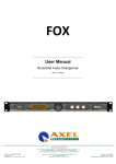
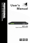
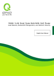
1
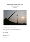
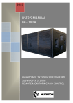
DSP Power Amplifier Module PDA500P User’s Manual Class D 500W+500W or 1kW in BTL with DSP Vers 1.1 Designed in Italy Assembled in China SEED Guangzhou Electronic LTD. 4F/5F, Build B, No.885, Shenzhou Road, Guangzhou, China Tel:+86 (20) 62845258 - www.marani.com.cn - [email protected] PDA500P User Manual Introduction Marani PDA500P amplifier module provides exceptionally high power density and powerful integrated DSP features, making it suitable for a broad range of loudspeaker applications. PDA500P amplifier module features analog inputs with link output; comprehensive DSP functions (crossover, parametric EQ, delay and limiter control); network control via RS485 on Cat-5 cable . Explanation of Graphical Symbols The lightning ash with arrowhead symbol within an equilateral triangle is intended to alert the user to the presence of uninsulated “dangerous voltage” within the product’s enclosure that may be of sufficient magnitude to constitute a risk of electric shock to humans. The exclamation point within an equilateral triangle is intended to alert the user to the presence of important operating and maintenance (servicing) instructions in the literature accompanying Important safety instructions Read the information for use (User Manual). Please keep the User Manual in a safe place during the lifetime of the product. The User Manual forms an integral part of the product. Heed all warnings. Follow all instructions. Do not use this product near water (for example, in damp rooms or near a swimming pool). Clean only with dry cloth. Do not cover the heat sink. Install in accordance with the User Manual. Do not install near any heat sources such as radiators, heat registers, stoves, or other apparatus that produce heat. Protect the power cord from being walked on, pinched or damaged in any other way. Pay particular attention to plugs and the point where they exit from the Amplifier Unit. The product may only be used in accordance with the information provided in the User Manual. Before and during the usage of the amplifier please ensure that all recommendations, especially the safety recommendations in the User Manual, are adhered to. The Amplifier Unit is designed for the amplification of pulsed audio signals and the Amplifier Unit should only be connected to speakers with an average impedance that is not lower than the impedances specified in the User's Manual. Designed in Italy Assembled in China PDA500P User Manual Damages that require service: Unplug the Amplifier Unit from the mains supply and refer to your dealer/distributor or other authorized repair workshop. Servicing is required when: - The power-supply cord or plug has been damaged. - Liquid has been spilled or objects have fallen into the amplifier. - The amplifier has been exposed to rain or moisture. - The amplifier has been dropped or suffered damage in any other way. - The amplifier exhibits a distinct change from its normal function or performance. Servicing: Do not attempt to service this product yourself. As opening or removing covers may expose you to dangerous voltage or other hazards, the amplifier may only be opened by qualified personnel. Please refer to your dealer/distributor. Servicing and Replacement Parts: All service and repair work must be carried out by an authorized dealer/distributor. When replacement parts are required, please ensure that the dealer/distributor only uses replacement parts specified by the manufacturer. The use of unauthorized replacement parts may result in injury and/or damage through fire or electric shock or other electricityrelated hazards. Safety Check: Upon completion of any service or repairs to this product, ask the dealer/distributor to perform safety checks to determine that the amplifier is in proper operating condition. Read the information for use (User Manual): When shipping the product, always use the original shipping carton and packing materials. For maximum protection, repack the unit as it was originally packed at the factory. Environments: Use this product only in E1, E2, E3 or E4 environments according to EN55103-2. “Electromagnetic compatibility – Product family standard for audio, video and audio-visual entertainment lighting control apparatus for professional use – Part 2: Immunity”. Ventilation and heat sink: The heatsink is provided to ensure reliable operation of the Amplifier Unit and to protect it from overheating. The heat sink must not be blocked or covered. This product should not be installed unless proper ventilation is provided or manufacturer’s instructions have been adhered to. Water and Moisture: Do not use this product near water (for example, in damp rooms or near a swimming pool). Cleaning: Unplug the Amplifier Unit from the wall outlet before cleaning. Do not use liquid or aerosol cleaners. Power-cord Protection: Power supply cords should be routed so that they are not likely to be walked on or pinched by items placed upon them or against them, paying particular attention to cords and plugs, and the point where they exit from the Amplifier Unit. Lightning: For added protection of the product during lightning storms, or when it is left unattended and unused for long periods of time, unplug it from the wall outlet. This will prevent damage to the product due to lightning and power-line surges. Disconnection from the mains power supply can only be achieved by removing the plug from the mains socket and by external disconnection of all poles from the mains. Interference of external objects and/or liquids with the appliance: Never push objects of any kind into this product through openings as they may touch dangerous voltage points or short out parts that could result in a fire or electric shock. Never spill liquid of any kind on the amplifier. Designed in Italy Assembled in China PDA500P User Manual Accessories: Do not place this product on an unstable cart, stand, tripod, bracket, or table. The product may fall, causing serious injury, and serious damage to the product. Any mounting of the product should follow the manufacturer’s instructions, and should use a mounting accessory recommended by the manufacturer. Connecting: When you connect the Amplifier Unit to other equipment, turn off the power and unplug all of the equipment from the supply source. Failure to do so may cause an electric shock and serious personal injury. Read the User's Manual of the other equipment carefully and follow the instructions when making the connections. Sound Volume: Reduce the volume to minimum before you turn on the amplifier to prevent sudden high levels of noise which may cause hearing or speaker damage. Designed in Italy Assembled in China Overwiev The PDA500P on the front panel offer the possibility to select up to 8 presets, edited and uploaded on the unit through a Rotary encoder. The Presets can be created thanks a Pc Sw which controls the unit via a RS485 interface. The PDA500P can be put in network with twin modules and controlled within a single Pc interface. The PDA500P is a powerful Class D BiAmp module for active cabinets, allowing the user to process the Input signal with first class 24bit/96kHz DSP processes, both for filtering purposes and dynamic ones. The all DSP processes can be accessed by the cabinets' manufacturer for the specific acoustic characterization of the cabinet itself,and by the user for the application personalization. For the Cabinets' manufacturers, 5 paramteric filters (Peaker or Variable Q Shelving) are available on the Input path of the signl, so as a RMS compressor operating on both Low/High outputs, and fed by the Low output path signal. On the Low/High ways, Lp/Hp filters up to 48dB/Oct are available, so as up to 15ms Delay, one firs/second order All Pass filter for phase control purposes, 5 parametric filters (Peaker or Variable Q Shelving ), RMS compressor and Clip Limiter. The all processes available to the manufacturers (Factory) are under Password. On the PDA500P Panel, a Master Input Gain is available for the simultaneous level control of the input level control; 3 leds are indicating the Input Signal presence, the Limiter activity and the Power On/Off of the unit. Designed in Italy Assembled in China PDA500P User Manual Main Features USER Available Processes on the Main Input path White/Pink Noise Generator White and Pink Noise Generator with Level controls from -40 up to 0dB Noise Gate: From -80dB up to -50dB Threshold, or Bypass Input Gain: from -12dB up to 12dB Parametric Equalization: 5 filters assignable as Bell or Shelving Filters: Symmetrical Bell or High/Low Variable Q Shelving Filter gain: for Bell and Shelving the gain is ranging from -12dBu up to +6dBu by 0.5dBu resolution steps Center frequency: selectable with a 1/24th of octave resolution steps from 20Hz up to 20kHz Filter Q: Q from 0.5 up to 10 by 0.1 resolution steps. Each Filter of the Eq can be singularly “Bypassed” once set. HPF: from 1st order (Butterworth -6dB/Oct) up to 4th Order (Butterworth, Linkwitz or Bessel -24dB/Oct) Delay 9.998ms by 10.4us increment/decrement step FACTORY Available Processes on the LOW/HIGH Input path X-Over Section: Hp/LP Filters up to 48dB/Oct X-Over Section: from 1st order (Butterworth -6dB/Oct) up to 8th Order (Butterworth, Linkwitz or Bessel -48dB/Oct) LPF on Outputs: from 1st order (Butterworth or Bessel -48dB/Oct) Filter’s Cutting Frequency steps Parametric Equalization: 1/24th of octave Filters: Symmetrical Bell or High/Low Variable Q Shelving Filter gain: for Bell and Shelving the gain is ranging from -12dBu up to +6dBu by 0.5dBu resolution steps Center frequency: selectable with a 1/24th of octave resolution steps from 20Hz up to 20kHz Filter Q: Q from 0.5 up to 10 by 0.1 resolution steps Each Filter of the Eq can be singularly “Bypassed” once set. RMS Compressor: RMS compressor fed from the Filters section output Drive: from -12dBu up to 6dBu Threshold: from 6dBu up to -24dBu -6dB/Oct) up to 8th Order (Butterworth, Linkwitz 7 filters assignable as Bell or Shelving Designed in Italy Assembled in China PDA500P User Manual Ratio: 1:1 (Bypass) up to 100:1 (Limiting), with Ratio Slope computed on Log Table with 0.1dB steps precision Noise Gate: Soft/Hard IAttack time: Attack time from 5ms up to 100ms (1ms resolution up to 20ms, then 10ms resolution up to 100ms) Release time: from 0.4 sec up to 1 sec (0.1sec resolution) Output Volume: from -18dBu up to 18dBu All Pass Filter: First (90Deg) and Second (180Deg) order All Pass filters. The second order All Pass has a variable Q ranging from 0.5 up to 10 Delay 9.998ms by 10.4us increment/decrement step Super User Processes RMS Compressor: RMS compressor fed from the Filters section output Drive: from -12dBu up to 6dBu Threshold: from 6dBu up to -24dBu Ratio: 1:1 (Bypass) up to 100:1 (Limiting), with Ratio Slope computed on Log Table with 0.1dB steps precision Knee: Soft/Hard Release time Attack time from 1ms up to 3sec (1ms resolution up to 20ms, then 10ms resolution up to 100ms, then 100ms resolution up to 3sec) Hold time: from 40ms sec up to 3 sec (10ms resolution up to 200ms, then 100ms resolution up to 3sec) Peak Limiter: fast PEAK Limiter fed from the all previous processes output Threshold: from 12dBu up to -18dBu Attack time: Attack time from 1ms up to 100ms (1ms resolution up to 20ms, then 10ms resolution up to 100ms) Release time: Release time from 40 ms up to 1 sec (10ms resolution up to 200ms, then 100ms resolution up to 1sec) Designed in Italy Assembled in China PDA500P User Manual Operating Mode The PDA500P can work as a stand alone unit [Stand Alone Mode], where up to 8 preset can be recalled by directly selecting them through the 8 positions encoder available on the front panel, or can work as completely remotely controlled unit [Remote Control Mode]. As soon as is turned ON the device will load the currently selected preset, depending from the current position of the Preset Eq encoder. The Power Led will turn ON (Red) and the unit will be ready to work. Stand Alone Mode When the PDA500P is operating as stand alone unit, so running one of the 8 available presets, previously created and stored within the unit with the remote control PC SW, the only available control are the 8 “preset encoder”, allowing to select 1 of the 8 available presets previously stored through the PC SW Remote Control. In Stand Alone Mode, the only indications of the “Activity” of the PDA500P in terms of running processes and signal status, can be checked thanks to the Signal Led, indicating if Signal is present at the module Input and the Limit Led indicating when on, if the DSP is dynamically compressing/Limiting the audio signal and indicating an Input Clip condition when blinking. The Input Signal can be sent to the unit through any one of the Male/Female XLR connectors. The one not used can be used for mirroring the Input signal to an other unit. The available potentiometer can help to control the Signal Input Level. Remote Control Mode When the PDA500P is operating as stand alone unit, so running one of the 8 available presets, previously created and stored within the unit with the remote control PC SW, the only available control are the 8 “preset encoder”, allowing to select 1 of the 8 available presets previously stored through the PC SW Remote Control. In Stand Alone Mode, the only indications of the “Activity” of the PDA500P in terms of running processes and signal status, can be checked thanks to the Signal Led, indicating if Signal is present at the module Input and the Limit Led indicating when on, if the DSP is dynamically compressing/Limiting the audio signal and indicating an Input Clip condition when blinking. The Input Signal can be sent to the unit through any one of the Male/Female XLR connectors. The one not used can be used for mirroring the Input signal to an other unit. The available potentiometer can help to control the Signal Input Level. Designed in Italy Assembled in China PDA500P User Manual PC Sw Remote Control Operations The PDA500P can be controlled by a Remote Control Sw running on Pc, allowing to fully edit the all processes available on each channel of the PDA500P. More, once created the desired configurations and selected the desired processes, the complete set up can be stored within the PDA500P and recalled later on as preset also when the unit is working in Stand Alone Mode. Once launched the Pc Sw Remote Control, previously installed on Pc (for the installation it is enough to run the “Installation Sw” and to install also the USB driver which installation instruction are on the CD containing the Remote Control Sw and coming with the PDA500P), the following screen shot will appear on the Pc: The screen above is allowing to set the RS485 connection parameters. With the RS485: the RS485 connection has to be selected when the PDA500P is connected to the PC through the RS485 line. In this case the PDA500P will be controlled as one of a NET of chained units, being allowed the net control of more units when using the RS485 connection. In the RS485 mode (chosen by “checking” the RS485 button on the “Communication Port” frame), need to assign the proper “COM” port in order to match the COM port assigned by the Pc to the “USB to Serial Port” within the Device Manager window at the “Ports (COM&LPT)” directory. When selected the RS485 connection, more PDA500P can be connected all together. In order this to happen, need the all units (connected in net and up to 32) to be identified by DIFFERENT ID number. In order the units to have a different ID, need to pre-assign to the all units used in net a specific ID number. When selected the RS485 mode, this can be done connecting one by one the units to be used in net and assigning to anyone of them an ID through the “Configure ID Device” button. When a Unit is connected, pressing the “Configure ID Device” it is possible to enter a window allowing to assign to the unit the ID number. NOTE: for avoiding problems is highly suggested to work with COM ports number within the 10. Designed in Italy Assembled in China PDA500P User Manual Once selected the desired connection, pressing the “OK” button the Main Environment Window of the Pc Sw will open: Double clicking on the Unit's name which processes/parameters have to be edited, the editing environment of the selected unit will open. Designed in Italy Assembled in China PDA500P User Manual INPUT PAGE The Input page is entered without any request of Password and is freely accessible by the User. Together with the Input Page, also the main functions of presets saving/storing and loading/recalling are accessible on a top bar, so as a SETUP control for setting the PDA500P module operative mode. Also a LOCK button is available for making active the Output Channels Editing pages (under Password) and a Compression/Limiting Master edigint page (also under Password). Finally a Side Bar showing a Vu-Meters section is displayed. The top Bar and the Vu-Meters Section, will be EVER available also from the Output Editing pages and Compression/Limiting page, accessible under Password. TOP BAR From the Top Bar, the following actions can be taken LOAD Preset: pressing this button, a standard page for selecting a directory on the Pc from where to load a Preset on the DSP, will open. The user can load from the selected directory a preset which will become the current configuration (Input and Outputs setting and Operative Mode) run by the DSP. SAVE Preset: pressing this button, a standard page for selecting/creating a directory where to save a Preset on the Pc, will open. The user can save within the selected directory the current edited configuration (Input and Outputs setting and Operative Mode) and assign to Preset the desired NAME. Designed in Italy Assembled in China PDA500P User Manual STORE Preset: the PDA500P has the possibility to store within its on board Eeprom up to 8 Presets recallable by the back panel Encoder. From the Pc Sw is possible to store within the PDA500P Eeprom the 8 presets, naming them as desired and allocating them in locations numbered from 1 to 8, with the desired sequence. Pressing the STORE Preset button, a particular page for naming and assigning a location within the DSP board's Eeprom, will open The user can store within at the selected position within the DSP board Eeprom (position assigned by the Select Position scroll window) the currently edited setting with the desired name, assigned within the EDIT NAME frame. Selected directory the current edited configuration (Input and Outputs setting and Operative Mode) and assign the the Preset the desired NAME. A name with up to 16 characters lentgh can be assigned RECALL Preset: From the Pc Sw is possible to recall from the PDA500P Eeprom any of 8 presets, there where presets were previously stored following the STORE Preset procedure. Pressing the RECALL Preset button, a particular page for will open The user can recall from the selected position within the DSP board Eeprom a previously stored preset and making it the currently ran by the DSP and the currently edited in its parameters by the Pc Sw. Designed in Italy Assembled in China PDA500P User Manual SETUP: pressing the SETUP button, it is possible to decide the operative mode of the PDA500P The PDA500P can work both in SE 2 Ways mode, providing 2x500W/4Ohm, or in BTL mode, where working in bridge mode can deliver 1kW/8Ohm on a mono output . Depending from the selected Operative Mode, the Output Editing pages will differ and in case of the BTL mode, they will be grouped in just one set of processes and the DSP will automatically create the outputs for the DPA500P to work in BTL mode (see the Editing Output Pages in 2Ways and BTL Mode paragraph). NOTE: when using the PDA500P in Bridge Mode, please foolow the Pascal Audio S-PRO2 setting indications for the S-PRO2 Amplifier Module Output setting. More, need to Ground the Pin 10 of the DSP I/O board connector if wanted to use the PDA500P in Bridge mode driving a 4 Ohm Load. LOCK: The LOCK Button, when pressed, is opening a window requiring a Password for entering the Output pages or/and the Main Compression/Limiting Page. Particularly, if pressed the LOCK button and provided the Password = OUTPUT (not case sensitive), the Output Pages will be available for editing and they will be selectable from button that will appear on the top bar and again pressing the LOCK button and provided the Password = LIMCMP (not case sensitive), the Main Compression/Limiting Page will be available for editing and will be selectable from button that will appear on the top bar In all the above cases, when Unlocked the Output or/and Master Compression/Limiting pages, the pages can be entered just pressing the related button on the top bar. Designed in Italy Assembled in China PDA500P User Manual Vu-Meters Right Side Bar As the Top Bar, the Vu-Meters and Temperature Bar is ever present during the editing of any Input, Output or Main Compression/Limiting Pages. This because this bar is displaying “Status” parameters which is necessary to have under control during the editing operations within anyone of the mentioned pages. Particularly, the Vu-Meters and Temperature bar is continuously displaying the following parameters: Temperature: here is displayed the Temperature Level expressed in Celsius degrees and taken by a temperature sensor located on the metal heat-sink dissipating the heat of the all power parts of the SPRO2 module. Input Levels: this set of meters is displaying.... Before Gain: the ABSOLUTE Input Level. The value displayed here is the Level of the Input Signal SOON after the A/D converter, so this is a very important indicator, which is showing, in case of CLIP, that the Level reduction, in order to avoid distortion, can be operated ONLY reducing the Analog Input Level through the external potentiometer. After Gain: the Input Level to the DSP processes, AFTER the GAIN control. The value displayed here is the Level og the Input Signal adjusted by the Input Gain Control. Stereo Cmp: this meter is displaying in negative dB, the action, in terms of RMS Compression, of the Main Compressor on the Input Signal, for containing any eventual excess of Power request in time, in order to avoid the SPRO2 entering protection conditions or reduced power delivery due to an excess of lasting request of power from the system (see later) Limiter: this meter is displaying in negative dB, the action, in terms of Limiting, of the Main Limiter on the Input Signal. Particularly, this Limiter is working as Side Chain Peak Limiter on the detection of overow detected by the DSP in its own internal processes: if an overow in one of the internal processes is detected, the Limiter goes quickly to limit the Input level of the Signal BEFORE to ow into the following processes, so to guarantee to avoid heavy digital overow (clipping) conditions.(see later) Output Low/High Levels: this set of meters is displaying.... Before Cmp: the value displayed here is the Level of the Processed Signal after the all filtering and BEFORE the RMS Compressor available on both Low and High ways path. This meter is indicating if any overload is occurring before the compressors action. After Vol: the value displayed here is the Level of the Processed Signal after the RMS compression and AFTER the Output Level, operating also as Make-Up for the signal passed through the RMS compression action. This is the Output Level going to the Amplifier Stage input. Compressor: this meter is displaying in negative dB, the action, in terms of RMS Compression, of the Compressor on the Output Signal path, after the all filtering processes. Designed in Italy Assembled in China PDA500P User Manual Input Page Processes From the “Input” Page all the available processes on the Input Path can be available for editing without the On the Input path the available processes are the following: Noise Gate: In the signal path, the first process which is found by the signal is the Noise Gate. The Noise Gate process can be made active or skipped through the Noise Gate check-box If the Noise Gate is selected, then the parameters for setting it will be active in the Noise Gate frame. Within the “Noise Gate” frame, the Main parameters of the Noise Gate process can be set: Threshold: is representing the Threshold of the Noise Gate activation. If the averaged peak of the Input Signal is remaining below this threshold, the Noise Gate become active; thresholds are available from -50dBu up to -80dBu with steps of -5dBu. Release Time: is representing the “speed” in exiting the Gated signal condition, when detected a Input Signal Peak exceeding the Threshold level. Available Release Times are going from 10ms up to 1sec. Attack Time: is representing the “speed” in Entering the Gated signal condition, when detected an averaged Input Signal Peak bellowing the Threshold level. Available Attack Times are going from 0.5sec up to 1sec. Designed in Italy Assembled in China PDA500P User Manual Source and Gain: The PDA500P is making available as Input source together with the external analog signal, also an internal noise generator, providing to the user the possibility to test the system using a White or Pink Noise internally generated. As said, checking the Noise Generator box within the SOURCE frame, a White or Pink Noise can be generated by the Unit, which level can be set from -40dBfs up to 0dBfs. IMPORTANT NOTE: the White and Pink Noise Generators are not filtering the generated noise, therefore, when using them, need to make sure that if not set in the current presets any Hp Filter with higher frequency than 20Hz and Higher slope than 12dB/Oct, so as no Low Pass filter on the High path is set at 20kHz with a slope higher than 18dB/Oct, then for a proper measurement NEED to set filters as follow: HP @ 22.4Hz Butterworth with 12dB/Oct slope (-6dB Corner at 22.4Hz) LP @ 20kHz Butterworth with 18dB/Oct slope (-12dB Corner at 22.4kHz) The Noise Signal generator is ijecting the signal soon after the noise Gate and BEFORE the Gain Control, which will be available for a further control of the generated Noise leve Gain: with this control it is possible to set the Input Level from -12dB to +12dB Phase: checking or left unchecked the box of the PHASE frame, it is possible to set the Input Signal Polarity; the polarity can be “Normal” (box unchecked) or “Inverted” (which means rotated of 180 Degrees, with the box checked). DLF: checking the DLF box, a Dynamic Loudness Filter ca be made active. The Dynamic Loudness is intended to provide a Dynamic Adjustment of the Low and High frequencies amount on the base of the Input Signal level. This in order to, there where the system is used with a not specific music program and there where there is the possibility to use the system for background music application, with low input signal level, to get more intelligibility and pleasure in the sound perception. To know more about the technical characteristics of the DLF, please check the “DFL Dynamic Loudness Filter Table” paragraph at the end of this documents. High Pass Filter: from this frame it is possible to set the Output Channels High Pass Filter (HPF). “Frequency”: (Low Cut frequency) the selectable frequencies range is from 20Hz to 20kHz in steps of 1/24 of an Octave. “Slope”: allows you to select the X-Over's High Pass Filter Shape and Order. The available shapes and orders for the High Pass Filter are listed below: – – – – – – – – – Designed in Italy Assembled in China No cut-off Buttw 6dB Buttw 12dB LRiley 12dB Bessel 12dB Buttw 18dB Buttw 24dB LRiley 24dB Bessel 24dB (High Pass Filter Bypassed) (Butterworth Filter 6dB/Oct Slope) (Butterworth Filter 12dB/Oct Slope) (Linkwitz/Riley Filter 12dB/Oct Slope) (Bessel Filter 12dB/Oct Slope) (Butterworth Filter 18dB/Oct Slope) (Butterworth Filter 24dB/Oct Slope) (Linkwitz/Riley Filter 24dB/Oct Slope) (Bessel Filter 24dB/Oct Slope) PDA500P User Manual Delay : from this frame it is possible to set the Output Channels Delay Time from 000.0000mS (0 meters) up to 9.998mS (3.39932 Meters), by steps of 1ms (Adj arrows) or 10.4us (Fine arrows). 5 Bands Parametric Equalizer: The PDA500P allows the user to select either Bell or variable Q Shelving Parameters and assign them independently using the 5 available filters. The selection can be done just pressing the “Peak Eq” button on top of the filters' gain sliders and selecting one of the 3 available filters' type: Peaker, variable Q high Shelving and variable Q low Shelving. BELL filter Center Frequency, Band Width (Q) and Gain can be adjusted. “Center Frequency”: the selectable frequencies range is from 20Hz to 20kHz in steps of 1/24 of an Octave. “Q factor”: the selectable Q range is from 0.5 up to 10 in steps of 0.1 Q. “Gain”: the selectable Gain range is from -12dB to +6dB in steps of 0.5 dB. Variable Q Low Shelving Filter: Center Frequency, Band Width (Q) (Slope) and Gain can be adjusted. “Center Frequency”: the selectable frequencies range is from 20Hz to 20kHz in steps of 1/24 of an Octave. “Q factor (Slope)”: the selectable Q range is from 0.5 up to 3 in steps of 0.1Q “Gain”: the selectable Gain range is from -12dB to +6dB in steps of 0.5 dB. Variable Q High Shelving Filter: Center Frequency, Band Width (Q) (Slope) and Gain can be adjusted. “Center Frequency”: the selectable frequencies range is from 20Hz to 20kHz in steps of 1/24 of an Octave. “Q factor (Slope)”: the selectable Q range is from 0.5 up to 10 in steps of 0.1Q. “Gain”: the selectable Gain range is from -12dB to +6dB in steps of 0.5 dB. Note: each single filter can be independently “bypassed” for an easy setting/use of them. To “Bypass” the single filter, just press the “Bypass” button beneath the filter’s parameters. The set up of the filters and specially their frequency placement can also be done with the use of the mouse, just activating the “Cursor” function, pressing the related button on the left bottom of the frequency response Graphic. Designed in Italy Assembled in China PDA500P User Manual Once the all 5 available cursor are shown on the Frequency Response graphic, just selecting anyone of them with the mouse's arrow and maintaining the mouse's click pressed, it is possible to move and place the selected cursor on the desired frequency and with the desired gain. For setting the filter's Q, still need to enter the desired value directly in the dedicated box in the filters' editing frame. Mute and Enable Windows: Check-boxes and Mute buttons are available on the Input page. Noise Gate: this check box allows to make the Noise Gate Active or not. Only when checked the box, the Noise gate will be active and its parameters editable Equalizer: this check box is allowing to bypass an already set up equalizer configuration, for test purposes; once unchecked the box, the EQ setting will be automatically rescued Mute Input: Input Signal Mutes (No Outputs on both outputs ways) Mute Low: Low Path Output Signal Muted Mute High: High Path Output Signal Muted Designed in Italy Assembled in China PDA500P User Manual OUTPUT PAGES (2-way mode) Low Output Page Processes As previously described, this page can only be entered providing the OUTPUT password when pressed the LOCK button from the Input Page. From the “Low Output” Page all the available processes on the Low Output Path can be available for editing On the Low Output path the available processes are the following: All Pass Filter 1st/2nd Ord: In the All Pass Filters frame, a First or Second order All Pass Filter can be selected. All Pass 1stOrd: Filters allowing a FLAT Amplitude response and adding a 90 Degree Phase rotation at the selected Frequency. If we selected an All Pass filter of the 1st order, then Phase Rotation Frequency has to be set at a desired value selectable in the Frequency frame The selectable frequencies range is from 20Hz to 20kHz in steps of 1Hz For the 1st Order All Pass, no Q adjustment is allowed. All Pass 2ndOrd: filters allowing a FLAT Amplitude response and adding a 180 Degree Phase rotation at the selected Frequency. If we selected an All Pass filter of the 2nd order, then Phase Rotation Frequency has to be set at a desired value selectable in the Frequency frame The selectable frequencies range is from 20Hz to 20kHz in steps of 1Hz For the 2nd Order All Pass, a Q adjustment is allowed: the selectable Q range is from 0.5 up to 10.0 in steps of 0.1. Designed in Italy Assembled in China PDA500P User Manual Delay: from this frame it is possible to set the Output Channels Delay Time from 000.0000mS (0 meters) up to 9.998mS (3.39932 Meters), by steps of 1ms (Adj arrows) or 10.4us (Fine arrows). Phase: checking or left unchecked the box of the PHASE frame, it is possible to set the Input Signal Polarity; the polarity can be “Normal” (box unchecked) or “Inverted” (which means rotated of 180 Degrees, with the box checked). Dynamic Filter: on the Low path, the PDA500P make available a Dynamic Filter in attenuation for Driver Protection purpose. The Dynamic Filter can be set by the user on the base of his requirement and can guarantee up to -12dB attenuation from the Max Signal level at the desired Frequency. Particularly, the attenuation is operated with a Speed that can be set by the user so as the rescue of the full Dynamic can be set by the user. Filter: within this frame, can be set the Frequency where need the attenuation to take place, the Q of the attenuating filter, for deciding the width of the attenuated area around the desired Frequency and the attenuation level in dB from the Maxsignal level. Attack: is the speed in attenuating operated by the dynamic filter. Release: is the speed of the filter in rescuing the Signal original amplitude when lower than Max Lev-Gain. High Pass Filter: from this frame it is possible to set the Output Channels High Pass Filter (HPF). “Frequency”: (Low Cut frequency) the selectable frequencies range is from 20Hz to 20kHz in steps of 1/24 of an Octave. “Slope”: allows you to select the X-Over's High Pass Filter Shape and Order. The available shapes and orders for the High Pass Filter are listed below: – – – – – – – – – – – – – No cut-off Buttw 6dB Buttw 12dB LRiley 12dB Bessel 12dB Buttw 18dB Buttw 24dB LRiley 24dB Bessel 24dB Buttw 36dB LRiley 36dB Buttw 48dB LRiley 48dB Designed in Italy Assembled in China (High Pass Filter Bypassed) (Butterworth Filter 6dB/Oct Slope) (Butterworth Filter 12dB/Oct Slope) (Linkwitz/Riley Filter 12dB/Oct Slope) (Bessel Filter 12dB/Oct Slope) (Butterworth Filter 18dB/Oct Slope) (Butterworth Filter 24dB/Oct Slope) (Linkwitz/Riley Filter 24dB/Oct Slope) (Bessel Filter 24dB/Oct Slope) (Butterworth Filter 36dB/Oct Slope) (Linkwitz/Riley Filter 36dB/Oct Slope) (Butterworth Filter 48dB/Oct Slope) (Linkwitz/Riley Filter 48dB/Oct Slope) PDA500P User Manual Low Pass Filter: from this frame it is possible to set the Output Channels Low Pass Filter (LPF). “Frequency”: (High Cut frequency) the selectable frequencies range is from 20Hz to 20kHz in steps of 1/24 of an Octave. “Slope”: allows you to select the X-Over's Low Pass Filter Shape and Order. The available shapes and orders for the High Pass Filter are listed below: – – – – – – – – – – – – – No cut-off Buttw 6dB Buttw 12dB LRiley 12dB Bessel 12dB Buttw 18dB Buttw 24dB LRiley 24dB Bessel 24dB Buttw 36dB LRiley 36dB Buttw 48dB LRiley 48dB (High Pass Filter Bypassed) (Butterworth Filter 6dB/Oct Slope) (Butterworth Filter 12dB/Oct Slope) (Linkwitz/Riley Filter 12dB/Oct Slope) (Bessel Filter 12dB/Oct Slope) (Butterworth Filter 18dB/Oct Slope) (Butterworth Filter 24dB/Oct Slope) (Linkwitz/Riley Filter 24dB/Oct Slope) (Bessel Filter 24dB/Oct Slope) (Butterworth Filter 36dB/Oct Slope) (Linkwitz/Riley Filter 36dB/Oct Slope) (Butterworth Filter 48dB/Oct Slope) (Linkwitz/Riley Filter 48dB/Oct Slope) 7 Bands Parametric Equalizer: The PDA500P allows the user to select either Bell or variable Q Shelving Parameters and assign them independently using the 7 available filters. The selection can be done just pressing the “Peak Eq” button on top of the filters' gain sliders and selecting one of the 3 available filters' type: Peaker, variable Q high Shelving and variable Q low Shelving. Designed in Italy Assembled in China PDA500P User Manual BELL filter Center Frequency, Band Width (Q) and Gain can be adjusted. “Center Frequency”: the selectable frequencies range is from 20Hz to 20kHz in steps of 1/24 of an Octave. “Q factor”: the selectable Q range is from 0.5 up to 10 in steps of 0.1 Q. “Gain”: the selectable Gain range is from -12dB to +6dB in steps of 0.5 dB. Variable Q Low Shelving Filter: Center Frequency, Band Width (Q) (Slope) and Gain can be adjusted. “Center Frequency”: the selectable frequencies range is from 20Hz to 20kHz in steps of 1/24 of an Octave. “Q factor (Slope)”: the selectable Q range is from 0.5 up to 3 in steps of 0.1Q “Gain”: the selectable Gain range is from -12dB to +6dB in steps of 0.5 dB. Variable Q High Shelving Filter: Center Frequency, Band Width (Q) (Slope) and Gain can be adjusted. “Center Frequency”: the selectable frequencies range is from 20Hz to 20kHz in steps of 1/24 of an Octave. “Q factor (Slope)”: the selectable Q range is from 0.5 up to 10 in steps of 0.1Q. “Gain”: the selectable Gain range is from -12dB to +6dB in steps of 0.5 dB. Note: each single filter can be independently “bypassed” for an easy setting/use of them. To “Bypass” the single filter, just press the “Bypass” button beneath the filter’s parameters. The set up of the filters and specially their frequency placement can also be done with the use of the mouse, just activating the “Cursor” function, pressing the related button on the left bottom of the frequency response Graphic. Once the all 7 available cursor are shown on the Frequency Response graphic, just selecting anyone of them with the mouse's arrow and maintaining the mouse's click pressed, it is possible to move and place the selected cursor on the desired frequency and with the desired gain. For setting the filter's Q, still need to enter the desired value directly in the dedicated box in the filters' editing frame. Note: in the Eq graphic can be shown in the same time the filtering set up of the currently edited Low Out page, just pressing the LOW button. To the Low Output filter setting, in the graphic can be superposed also the set up of the other Signal path pages as the Input Filter setting, just pressing the INPUT+LOW button, or even the VIEW HIGH in order to visualize on the graphic the overall filter setting of the all Signal paths. Designed in Italy Assembled in China PDA500P User Manual RMS Compressor: from this frame it is possible to set the Threshold and Ratio parameters of the Low Output Channels RMS Compressor. The available parameters are the following... “Threshold”: the selectable range of the RMS Compressor's Threshold is from +12dBu (OFF) to -18dBu in steps of 0.1dBu “Ratio”: the selectable range of the RMS Compressor's Ratio is from 1:1 (Off) up to 100:1 (Lim) in steps of 1 . “Knee”: the selectable range of the RMS Compressor's Knee type is from 000% (Hard) up to 100% (Soft) “Release”: the selectable range of the RMS Compressor's Release Time is from 0.04sec to 1sec in steps of 0.01sec from 40ms up to 200ms, then 100ms from 200ms up to 1sec. “Attack”: the selectable range of the RMS Compressor's Attack Time is from 5ms to 100ms in steps of 1ms from 5ms to 20ms then 10ms from 20ms to 100ms. Note: The RMS Compressor Threshold is defined in dBu, due to the fact that with both, Sinusoid and Squared wave testing signals, the PDA500P compressed output dBu (RMS) Level is the same and matching the selected one. Checking the VIEW GRAPH box in the RMS Compressor frame, the RMS Compressor's setting can be graphically visualized in a graphic windows showing the Compressed Output in relation to the input signal to the compressor. The Compressor activity can be also temporarily bypassed checking the BYPASS box also within the RMS Compressor frame. The RMS Compressor on the Low Path and the one on the High Path, can be linked together, checking the LINK box, so to have both Signals of the Low and High path compressed by the same and lowest compression coefficient coming from the computations done on the Both Signals analysis made on the base of the respective settings. Level: with this control it is possible to set the Low Output Level from -18dB to +18dB. This control is acting on the signal coming from the RMS Compressor's output and entering the Amplifier's stage. Can be used also as Make Up control for the Compressor's Output. Designed in Italy Assembled in China PDA500P User Manual High Output Page Processes As previously described for the Low Output page, also this page can only be entered providing the OUTPUT password when pressed the LOCK button from the Input Page. From the “High Output” Page all the available processes on the High Output Path can be available for editing On the High Output path the available processes are the following: All Pass Filter 1st/2nd Ord: In the All Pass Filters frame, a First or Second order All Pass Filter can be selected. All Pass 1stOrd: filters allowing a FLAT Amplitude response and adding a 90 Degree Phase rotation at the selected Frequency. If we selected an All Pass filter of the 1st order, then Phase Rotation Frequency has to be set at a desired value selectable in the Frequency frame The selectable frequencies range is from 20Hz to 20kHz in steps of 1Hz For the 1st Order All Pass, no Q adjustment is allowed. All Pass 2ndOrd: filters allowing a FLAT Amplitude response and adding a 180 Degree Phase rotation at the selected Frequency. If we selected an All Pass filter of the 2nd order, then Phase Rotation Frequency has to be set at a desired value selectable in the Frequency frame The selectable frequencies range is from 20Hz to 20kHz in steps of 1Hz For the 2nd Order All Pass, a Q adjustment is allowed: the selectable Q range is from 0.5 up to 10.0 in steps of 0.1. Designed in Italy Assembled in China PDA500P User Manual Delay: from this frame it is possible to set the Output Channels Delay Time from 000.0000mS (0 meters) up to 9.998mS (3.39932 Meters), by steps of 1ms (Adj arrows) or 10.4us (Fine arrows). Phase: checking or left unchecked the box of the PHASE frame, it is possible to set the Input Signal Polarity; the polarity can be “Normal” (box unchecked) or “Inverted” (which means rotated of 180 Degrees, with the box checked). High Pass Filter: from this frame it is possible to set the Output Channels High Pass Filter (HPF). “Frequency”: (Low Cut frequency) the selectable frequencies range is from 20Hz to 20kHz in steps of 1/24 of an Octave. “Slope”: allows you to select the X-Over's High Pass Filter Shape and Order. The available shapes and orders for the High Pass Filter are listed below: – – – – – – – – – – – – – No cut-off Buttw 6dB Buttw 12dB LRiley 12dB Bessel 12dB Buttw 18dB Buttw 24dB LRiley 24dB Bessel 24dB Buttw 36dB LRiley 36dB Buttw 48dB LRiley 48dB (High Pass Filter Bypassed) (Butterworth Filter 6dB/Oct Slope) (Butterworth Filter 12dB/Oct Slope) (Linkwitz/Riley Filter 12dB/Oct Slope) (Bessel Filter 12dB/Oct Slope) (Butterworth Filter 18dB/Oct Slope) (Butterworth Filter 24dB/Oct Slope) (Linkwitz/Riley Filter 24dB/Oct Slope) (Bessel Filter 24dB/Oct Slope) (Butterworth Filter 36dB/Oct Slope) (Linkwitz/Riley Filter 36dB/Oct Slope) (Butterworth Filter 48dB/Oct Slope) (Linkwitz/Riley Filter 48dB/Oct Slope) Low Pass Filter: from this frame it is possible to set the Output Channels Low Pass Filter (LPF). “Frequency”: (High Cut frequency) the selectable frequencies range is from 20Hz to 20kHz in steps of 1/24 of an Octave. “Slope”: allows you to select the X-Over's Low Pass Filter Shape and Order. The available shapes and orders for the High Pass Filter are listed below: – No cut-off – Buttw 6dB – Buttw 12dB – LRiley 12dB – Bessel 12dB – Buttw 18dB – Buttw 24dB – LRiley 24dB – Bessel 24dB – Buttw 36dB – LRiley 36dB – Buttw 48dB – LRiley Designed in Italy 48dB Assembled in China (High Pass Filter Bypassed) (Butterworth Filter 6dB/Oct Slope) (Butterworth Filter 12dB/Oct Slope) (Linkwitz/Riley Filter 12dB/Oct Slope) (Bessel Filter 12dB/Oct Slope) (Butterworth Filter 18dB/Oct Slope) (Butterworth Filter 24dB/Oct Slope) (Linkwitz/Riley Filter 24dB/Oct Slope) (Bessel Filter 24dB/Oct Slope) (Butterworth Filter 36dB/Oct Slope) (Linkwitz/Riley Filter 36dB/Oct Slope) (Butterworth Filter 48dB/Oct Slope) (Linkwitz/Riley Filter 48dB/Oct Slope) PDA500P User Manual 7 Bands Parametric Equalizer: The PDA500P allows the user to select either Bell or variable Q Shelving Parameters and assign them independently using the 7 available filters. The selection can be done just pressing the “Peak Eq” button on top of the filters' gain sliders and selecting one of the 3 available filters' type: Peaker, variable Q high Shelving and variable Q low Shelving. BELL filter Center Frequency, Band Width (Q) and Gain can be adjusted. “Center Frequency”: the selectable frequencies range is from 20Hz to 20kHz in steps of 1/24 of an Octave. “Q factor”: the selectable Q range is from 0.5 up to 10 in steps of 0.1 Q. “Gain”: the selectable Gain range is from -12dB to +6dB in steps of 0.5 dB. Variable Q Low Shelving Filter: Center Frequency, Band Width (Q) (Slope) and Gain can be adjusted. “Center Frequency”: the selectable frequencies range is from 20Hz to 20kHz in steps of 1/24 of an Octave. “Q factor (Slope)”: the selectable Q range is from 0.5 up to 3 in steps of 0.1Q “Gain”: the selectable Gain range is from -12dB to +6dB in steps of 0.5 dB. Variable Q High Shelving Filter: Center Frequency, Band Width (Q) (Slope) and Gain can be adjusted. “Center Frequency”: the selectable frequencies range is from 20Hz to 20kHz in steps of 1/24 of an Octave. “Q factor (Slope)”: the selectable Q range is from 0.5 up to 10 in steps of 0.1Q. “Gain”: the selectable Gain range is from -12dB to +6dB in steps of 0.5 dB. Note: each single filter can be independently “bypassed” for an easy setting/use of them. To “Bypass” the single filter, just press the “Bypass” button beneath the filter’s parameters. The set up of the filters and specially their frequency placement can also be done with the use of the mouse, just activating the “Cursor” function, pressing the related button on the left bottom of the frequency response Graphic. Designed in Italy Assembled in China PDA500P User Manual Once the all 7 available cursor are shown on the Frequency Response graphic, just selecting anyone of them with the mouse's arrow and maintaining the mouse's click pressed, it is possible to move and place the selected cursor on the desired frequency and with the desired gain. For setting the filter's Q, still need to enter the desired value directly in the dedicated box in the filters' editing frame. Note: in the Eq graphic can be shown in the same time the filtering set up of the currently edited High Out page, just pressing the HIGH button. To the High Output filter setting, in the graphic can be superposed also the set up of the other Signal path pages as the Input Filter setting, just pressing the INPUT+HIGH button, or even the VIEW LOW in order to visualize on the graphic the overall filter setting of the all Signal paths. RMS Compressor: from this frame it is possible to set the Threshold and Ratio parameters of the Low Output Channels RMS Compressor. The available parameters are the following... “Threshold”: the selectable range of the RMS Compressor's Threshold is from +12dBu (OFF) to -18dBu in steps of 0.1dBu “Ratio”: the selectable range of the RMS Compressor's Ratio is from 1:1 (Off) up to 100:1 (Lim) in steps of 1 . “Knee”: the selectable range of the RMS Compressor's Knee type is from 000% (Hard) up to 100% (Soft) and can be adjusted by rotating the “PM3” encoder. “Release”: the selectable range of the RMS Compressor's Release Time is from 0.04sec to 1sec in steps of 0.01sec from 40ms up to 200ms, then 100ms from 200ms up to 1sec. “Attack”: the selectable range of the RMS Compressor's Attack Time is from 5ms to 100ms in steps of 1ms from 5ms to 20ms then 10ms from 20ms to 100ms. Note: The RMS Compressor Threshold is defined in dBu, due to the fact that with both, Sinusoid and Squared wave testing signals, the PDA500P compressed output dBu (RMS) Level is the same and matching the selected one. Checking the VIEW GRAPH box in the RMS Compressor frame, the RMS Compressor's setting can be graphically visualized in a graphic windows showing the Compressed Output in relation to the input signal to the compressor. The Compressor activity can be also temporarily bypassed checking the BYPASS box also within the RMS Compressor frame. The RMS Compressor on the Low Path and the one on the High Path, can be linked together, checking the LINK box, so to have both Signals of the Low and High path compressed by the same and lowest compression coefficient coming from the computations done on the Both Signals analysis made on the base of the respective settings. Designed in Italy Assembled in China PDA500P User Manual Within the RMS Compressor Low Pass Filter frame, can be set a 6dB/Oct (butterworth) or 12dB/Oct (Linkwitz) X-Ovoer point at a frequency ranging from 5kHz up to 10kHz, allowing to split the high Output signal Band in 2 Sub Bands. The Lowest one will be subject to the Compression coefficient computed on the base of the RMS compressor setting and the upper band portion will instead left “free” and not subject to any compression. The level of the upper portion of the band can be controlled separately by the Hi-level cursor, ranging between -18db and +18dB. This option, which can be skipped stting the SLOPE paramenter within the frame to “No cut-off”, has been intended for leaving brilliance on the high frequencies even when operated on the high path signal a heavy compression, there where the very hi end frequencies are not brining enough ebenrgy to damage the loudspeaker's parts. Level: with this control it is possible to set the Low Output Level from -18dB to +18dB. This cobntrol is acting on the signal coming from the RMS Compressor's output and entering the Amplifier's stage. Can be used also as Make Up control for the Compressor's Output. Designed in Italy Assembled in China PDA500P User Manual OUTPUT PAGE (Bridge mode) Output Page Processes As previously described, this page can only be entered providing the OUTPUT password when pressed the LOCK button from the Input Page. From the “Low Output” Page all the available processes on the Low Output Path can be available for editing. On the Low Output path the available processes are the following: All Pass Filter 1st/2nd Ord: In the All Pass Filters frame, a First or Second order All Pass Filter can be selected. All Pass 1stOrd: Filters allowing a FLAT Amplitude response and adding a 90 Degree Phase rotation at the selected Frequency. If we selected an All Pass filter of the 1st order, then Phase Rotation Frequency has to be set at a desired value selectable in the Frequency frame The selectable frequencies range is from 20Hz to 20kHz in steps of 1Hz For the 1st Order All Pass, no Q adjustment is allowed. All Pass 2ndOrd: filters allowing a FLAT Amplitude response and adding a 180 Degree Phase rotation at the selected Frequency. If we selected an All Pass filter of the 2nd order, then Phase Rotation Frequency has to be set at a desired value selectable in the Frequency frame The selectable frequencies range is from 20Hz to 20kHz in steps of 1Hz For the 2nd Order All Pass, a Q adjustment is allowed: the selectable Q range is from 0.5 up to 10.0 in steps of 0.1. Designed in Italy Assembled in China PDA500P User Manual Delay: from this frame it is possible to set the Output Channels Delay Time from 000.0000mS (0 meters) up to 9.998mS (3.39932 Meters), by steps of 1ms (Adj arrows) or 10.4us (Fine arrows). Phase: checking or left unchecked the box of the PHASE frame, it is possible to set the Input Signal Polarity; the polarity can be “Normal” (box unchecked) or “Inverted” (which means rotated of 180 Degrees, with the box checked). High Pass Filter: from this frame it is possible to set the Output Channels High Pass Filter (HPF). “Frequency”: (Low Cut frequency) the selectable frequencies range is from 20Hz to 20kHz in steps of 1/24 of an Octave. “Slope”: allows you to select the X-Over's High Pass Filter Shape and Order. The available shapes and orders for the High Pass Filter are listed below: – – – – – – – – – – – – – No cut-off Buttw 6dB Buttw 12dB LRiley 12dB Bessel 12dB Buttw 18dB Buttw 24dB LRiley 24dB Bessel 24dB Buttw 36dB LRiley 36dB Buttw 48dB LRiley 48dB (High Pass Filter Bypassed) (Butterworth Filter 6dB/Oct Slope) (Butterworth Filter 12dB/Oct Slope) (Linkwitz/Riley Filter 12dB/Oct Slope) (Bessel Filter 12dB/Oct Slope) (Butterworth Filter 18dB/Oct Slope) (Butterworth Filter 24dB/Oct Slope) (Linkwitz/Riley Filter 24dB/Oct Slope) (Bessel Filter 24dB/Oct Slope) (Butterworth Filter 36dB/Oct Slope) (Linkwitz/Riley Filter 36dB/Oct Slope) (Butterworth Filter 48dB/Oct Slope) (Linkwitz/Riley Filter 48dB/Oct Slope) Low Pass Filter: from this frame it is possible to set the Output Channels Low Pass Filter (LPF). “Frequency”: (High Cut frequency) the selectable frequencies range is from 20Hz to 20kHz in steps of 1/24 of an Octave. “Slope”: allows you to select the X-Over's Low Pass Filter Shape and Order. The available shapes and orders for the High Pass Filter are listed below: – – – – – – – – – – – – – No cut-off Buttw 6dB Buttw 12dB LRiley 12dB Bessel 12dB Buttw 18dB Buttw 24dB LRiley 24dB Bessel 24dB Buttw 36dB LRiley 36dB Buttw 48dB LRiley 48dB Designed in Italy Assembled in China (High Pass Filter Bypassed) (Butterworth Filter 6dB/Oct Slope) (Butterworth Filter 12dB/Oct Slope) (Linkwitz/Riley Filter 12dB/Oct Slope) (Bessel Filter 12dB/Oct Slope) (Butterworth Filter 18dB/Oct Slope) (Butterworth Filter 24dB/Oct Slope) (Linkwitz/Riley Filter 24dB/Oct Slope) (Bessel Filter 24dB/Oct Slope) (Butterworth Filter 36dB/Oct Slope) (Linkwitz/Riley Filter 36dB/Oct Slope) (Butterworth Filter 48dB/Oct Slope) (Linkwitz/Riley Filter 48dB/Oct Slope) PDA500P User Manual 7 Bands Parametric Equalizer: The PDA500P allows the user to select either Bell or variable Q Shelving Parameters and assign them independently using the 7 available filters. The selection can be done just pressing the “Peak Eq” button on top of the filters' gain sliders and selecting one of the 3 available filters' type: Peaker, variable Q high Shelving and variable Q low Shelving. BELL Filter Center Frequency, Band Width (Q) and Gain can be adjusted. “Center Frequency”: the selectable frequencies range is from 20Hz to 20kHz in steps of 1/24 of an Octave. “Q factor”: the selectable Q range is from 0.5 up to 10 in steps of 0.1 Q. “Gain”: the selectable Gain range is from -12dB to +6dB in steps of 0.5 dB. Variable Q Low Shelving Filter: Center Frequency, Band Width (Q) (Slope) and Gain can be adjusted. “Center Frequency”: the selectable frequencies range is from 20Hz to 20kHz in steps of 1/24 of an Octave. “Q factor (Slope)”: the selectable Q range is from 0.5 up to 3 in steps of 0.1Q “Gain”: the selectable Gain range is from -12dB to +6dB in steps of 0.5 dB. Variable Q High Shelving Filter: Center Frequency, Band Width (Q) (Slope) and Gain can be adjusted. “Center Frequency”: the selectable frequencies range is from 20Hz to 20kHz in steps of 1/24 of an Octave. “Q factor (Slope)”: the selectable Q range is from 0.5 up to 10 in steps of 0.1Q. “Gain”: the selectable Gain range is from -12dB to +6dB in steps of 0.5 dB. Note: each single filter can be independently “bypassed” for an easy setting/use of them. To “Bypass” the single filter, just press the “Bypass” button beneath the filter’s parameters. The set up of the filters and specially their frequency placement can also be done with the use of the mouse, just activating the “Cursor” function, pressing the related button on the left bottom of the frequency response Graphic. Designed in Italy Assembled in China PDA500P User Manual Once the all 7 available cursor are shown on the Frequency Response graphic, just selecting anyone of them with the mouse's arrow and maintaining the mouse's click pressed, it is possible to move and place the selected cursor on the desired frequency and with the desired gain. For setting the filter's Q, still need to enter the desired value directly in the dedicated box in the filters' editing frame. Note: in the Eq graphic can be shown in the same time the filtering set up of the currently edited Low Out page, just pressing the LOW button. To the Low Output filter setting, in the graphic can be superposed also the set up of the other Signal path pages as the Input Filter setting, just pressing the INPUT+LOW button, or even the VIEW HIGH in order to visualize on the graphic the overall filter setting of the all Signal paths. RMS Compressor: from this frame it is possible to set the Threshold and Ratio parameters of the Low Output Channels RMS Compressor. The available parameters are the following... “Threshold”: the selectable range of the RMS Compressor's Threshold is from +12dBu (OFF) to -18dBu in steps of 0.1dBu “Ratio”: the selectable range of the RMS Compressor's Ratio is from 1:1 (Off) up to 100:1 (Lim) in steps of 1 . “Knee”: the selectable range of the RMS Compressor's Knee type is from 000% (Hard) up to 100% (Soft) “Release”: the selectable range of the RMS Compressor's Release Time is from 0.04sec to 1sec in steps of 0.01sec from 40ms up to 200ms, then 100ms from 200ms up to 1sec. “Attack”: the selectable range of the RMS Compressor's Attack Time is from 5ms to 100ms in steps of 1ms from 5ms to 20ms then 10ms from 20ms to 100ms. Note: The RMS Compressor Threshold is defined in dBu, due to the fact that with both, Sinusoid and Squared wave testing signals, the PDA500P compressed output dBu (RMS) Level is the same and matching the selected one. Checking the VIEW GRAPH box in the RMS Compressor frame, the RMS Compressor's setting can be graphically visualized in a graphic windows showing the Compressed Output in relation to the input signal to the compressor. The Compressor activity can be also temporarily bypassed checking the BYPASS box also within the RMS Compressor frame. Level: with this control it is possible to set the Low Output Level from -18dB to +18dB. This control is acting on the signal coming from the RMS Compressor's output and entering the Amplifier's stage. Can be used also as Make Up control for the Compressor's Output. Designed in Italy Assembled in China PDA500P User Manual MAIN RMS Compressor and Peak Limiter Pages As previously described, this page can only be entered providing the LIMCMP password when pressed the LOCK button from the Input Page. From the “Main Compressor Limiter” Page can be set a RMS Compressor and a Peak Limiter. The RMS Compressor, is intended ton operate a compression on the Output Signal when the Signal Energy is lasting for too long time, due to the characteristic of the Input Signal (as a pure sinusoid in example), risking to compromise the Class D amplifier's performances. This RMS compressor has a HOLD TIME parameters that is allowing to set a time during the while the Compressor is blinded to the extra levels of the Signal. When the level of the signal is lasting too long over the specified threshold, exceeding the set Hold Time, the compressor start acting reducing the Output Signal level with a speed defined by the Attack Time. When the Input signal goes again below the threshold, the Compressor will release the Output Signal level at a speed defined by the Release time. Due to the presence also on the Out and High paths of RMS compressors already reducing the Output Signal Levels, the Main RMS Compressor with Hold Time, would have to be set with a Threshold lower than the ones set for the RMS Compressors on the Low and High paths, so to represent a threshold where to bring the Output signal when lasting too much time at an excessive level ...even after the RMS compressors on the Low and high paths. The Peak Limiter, it is operating on the Input Gain and is working on the base of any detected Overow occurring during the Signal Processing operated by the DSP. There where a potential Clip or overow comes from the internal DSP processes and not from the external Input Level, the Peak Limiter, instructed by an algorithm for the processes overow detection, will quickly go to reduce the input level so to resolve the occurring overow reducing the amount of signal passed to the DSP processes. Designed in Italy Assembled in China PDA500P User Manual RMS Cmpressor: from this frame it is possible to set following parameters of the Main RMS Compressor... “Drive”: the drive control is allowing to adjust the reference level to the Compressor input. It is ranging from -12dB up to +6dB. “Threshold”: the selectable range of the RMS Compressor's Threshold is from +12dBu (OFF) to -18dBu in steps of 0.1dBu “Ratio”: the selectable range of the RMS Compressor's Ratio is from 1:1 (Off) up to 100:1 (Lim) in steps of 1. . “Knee”: the selectable range of the RMS Compressor's Knee type is from 000% (Hard) up to 100% (Soft) “Attack”: the selectable range of the RMS Compressor's Attack Time is from 1ms to 3sec in steps of 1ms from 1ms to 20ms then 10ms from 20ms to 100ms, then 100ms steps up to 3sec. “Release”: the selectable range of the RMS Compressor's Release Time is from 0.04sec to 3sec in steps of 0.01sec from 40ms up to 200ms, then 100ms from 200ms up to 3sec. “Hold Time”: the selectable range of the RMS Compressor's Hold time is from 0.0sec to 10sec in steps of 0.05sec. Peak Limiter: from this frame it is possible to set following parameters of the Main RMS Compressor... “Limiter Threshold”: the selectable range of the Peak Limiter's Threshold is from +12dB (Limiter not active) to -18.0dB in steps of 0.1 dB. “Attack Time”: the selectable range of the Peak Limiter's Attack Time is from 1ms to 100ms in steps of 1ms from 1ms to 20ms then 10ms from 20ms to 100ms. “Release Time”: the selectable range of the Peak Limiter's Release Time is from 0.04s to 1s in steps of 0.01s. Designed in Italy Assembled in China PDA500P User Manual TECHNICAL SPECIFICATIONS 355mm - 13,99" 155mm 6,11" Power && Amplifier Amplifier Sections Sections Power Number of Channels -----------------Max Output Power @ 8 ohms--------Max Output Power @ 4 ohms--------Output Circuitry ----------------------Output Voltage -----------------------THD @ Rated power 4 (1kHz) ----Signal To Noise Ratio ------------------Frequency Response -----------------Damping Factor -----------------------Power Supply --------------------------Operating Range ---------------------Consumption / Current draw and --Thermal dissipation @ 230 V Protections ---------------------------- 2 2 x 250W 1 x 1000W (Bridge) 2 x 500W 1 x 1000W (4Ω BTL Mode selected) Class D - full bandwith PWM modulator with ultra low distortion 70 Vp / 140 Vpp (unloaded) / Bridged 140 Vp / 280 Vpp (unloaded) <0.05% (20 Hz - 20 kHz, 8Ω load, 3dB below rated power) >120 dB (A-weighted, 20 Hz - 20 kHz, 8 load) 20 Hz - 20 kHz ± 0,15 dB (8 load, 1 dB below rated power) >1000 (8 load, 1kHz and below) Switch mode power supply with PFC (Power Factor Correction) and integral standby converter Universal Mains, 85-265V 11.2W / -A / 38.3 BTU/h (Idle) 173W / -A / 143.4 BTU/h (I/8 max. power@4Ω) Over-Current, Over/Under Voltage, Output DC and Over-Temperature Audio Audio Analog Input ---------------------------Analog Output ------------------------AD & DA Converters -----------------Frequency Response (DSP) ----------- 1 x XLR electronically balanced, +12dB 1 x XLR electronically balanced (Link) Cs4272 24bit 20 Hz - 20 KHz; -0.5dBu at 20 Hz and 20 kHz DSP && Processing Processing DSP DSP Engine ----------------------------- Dream SAM3716, 24bit (data) x 96 bit (coeff.) DSP Resolution ------------------------- 24x32 bit for filtering process; 96 bits resolution on intermediate computation results Parametric Equalization --------------- 5 filters on input channel selected as Bell or Shelving 7 filters per output channel selected as Bell or Shelving Filter Type ------------------------------- Bell, Low/High Shelving as 1st /2nd Order Filter Gain ------------------------------- From -12dBu up to +6dBu by 0.5dBu resolution steps Center Frequency ---------------------- Selectable with a 1/24th of octave resolution step from 20Hz up to 20kHz Filter Q/BW ----------------------------- Q from 0.5 up to 10 by 0.1 resolution steps Crossover section HPF/LPF ----------- Butterworth 6/12/18/24/48dB per octave Bessel and Linkwitz-Riley 12/18/24/48dB per octave. Filter resolution 1/24th of octave Sophisticated Dynamic Loudness function and additional High-Pass filter per input section All-pass filter up to 2nd order per output section RMS Compressor ---------------------- Drive from -12 to 6dBu; Threshold from -18dBu up to -12dBu; Attack time from 5ms up to 100ms; Knee 0~100%; Ratio from 2:1 to 100:1; Release time from 40ms up to 1000ms (10ms resolution). Peak Limiter ---------------------------- Threshold from -18dBu up to +12dBu Release time from 40ms up to 1000ms (10ms resolution up to 200ms, 100ms res. up to 1000ms) Attack time from 1ms up to 100ms (1ms resolution up to 20ms, 10ms resolution up to 100ms) Delay ------------------------------------- 10 ms 21us increment/decrement steps per channel General General User Preset ---------------------------- 8 Panel ------------------------------------ GAIN pot. -30dBu ~ 0dBu PRESET EQ Rotary encoder switch Green LED (Power); Yellow LED (Limit); Blue LED (Signal presence) 1 x XLR female connector (Input) 1 x XLR male connector (Link Output) 2 x RJ45 connector (M-LAN Rs485) 2 X Locking PowerCON® 20A: AC Mains (blue) - AC Link (white) Dimensions ----------------------------- 13,99"x 2,8"x 6,11" (316x70x155mm) Weight, Net / Shipping ---------------- 3.52 lbs (1.6 Kg) / 4.96 lbs (2.5 Kg) Designed in Italy Assembled in China PDA500P User Manual DFL Dynamic Loudness Filter Table The dynamic Ludness Filter is a Dynamic Filtering process where 2 Bell Filters centered at Low and High Frequencies, gain dynamically on the base of the Input Signal Level. Particularly a Bell Filter is set at 50Hz for Contour purposes and a second one at 12kHz for High Freq. Enhancement. Both Filters are Gaining dependently from the Input Signal Level, in different way and on the base of different tables. Here following, the table describing what's the 50hz and 12kHz filters' gain on the base of the Input Signal Level detected. The dynamic Ludness Filter is a Dynamic Filtering process where 2 Bell Filters centered at Low and High Frequencies, gain dynamically on the base of the Input Signal Level. Particularly a Bell Filter is set at 50Hz for Contour purposes and a second one at 12kHz for High Freq. Enhancement. Both Filters are Gaining dependently from the Input Signal Level, in different way and on the base of different tables. Here following, the table describing what's the 50hz and 12kHz filters' gain on the base of the Input Signal Level detected. Designed in Italy Assembled in China PDA500P User Manual PDA500P Processes Block Scheme Designed in Italy Assembled in China PDA500P User Manual Designed in Italy Assembled in China SEED Guangzhou Electronic LTD. 4F/5F, Build B, No.885, Shenzhou Road, Guangzhou, China Tel:+86 (20) 62845258 - www.marani.com.cn - [email protected]