1
Notice
Please use the transceiver in
compliance with local regulations.
A Note To Users
Thank you for purchasing the Mobile
transceiver. We trust this transceiver will give
you convenient and reliable communication for
many years.
For the best experience, we advise that you
read this manual completely before using your
new transceiver.
I
Contents
Security Information .................................................. 1
Accessories & Options............................................... 2
Supplied Accessories.............................................. 2
Optional Accessories .............................................. 2
Installation.................................................................. 3
Connect Power ....................................................... 3
Keeping the Transceiver Cool ................................ 3
Install with Bracket ................................................ 4
Connect Accessories............................................... 4
Getting Acquainted..................................................... 6
DTMF Microphone Panel .......................................... 8
LCD Display ............................................................ 10
Front Panel Description............................................ 12
Basic Operation........................................................ 13
Power on/off......................................................... 13
Turn Volume......................................................... 13
Select Channel...................................................... 13
Transmitting and receiving................................... 14
Function Menu Operation ........................................ 15
Auto Power Off(APO): Menu 01 ......................... 16
APRO (APRO): Menu 02 .................................... 16
Busy Channel Lock (BC Lock): Menu 03............ 16
II
Key Beep (Beep): Menu 04.................................. 17
Channel Save (CHASave): Menu 05.................... 17
DTMF Function (DTMF): Menu 06 .................... 18
Dual Watch (DW): Menu 07 ................................ 23
Decode Type and Decode Code (Menus 08 and 09)
.............................................................................. 23
Encode Type and Encode Code (Menus 10 and 11)
.............................................................................. 25
FM Radio Function(FM): Menu 12...................... 26
FM Scan(FM Scan)): Menu 13.......................... 27
FM SQL (FM SQL): Menu 14 ............................. 27
FM DualWatch (FM DW): Menu 15.................... 28
Font size (Choose(Font): Menu 16 .................... 28
Key Lock Function (Keylock): Menu 17 ............. 28
Keypad Function(Keypad): Menu 18................... 29
Backlight (Lamp): Menu 19................................. 29
Setting Channel Names: (Name): Menus 20 /21/22
.............................................................................. 30
Set Opening Display (OpenDIS): Menu 23 ......... 31
Custom Keys Set (P1-P3、M Key): Menus 24-29
.............................................................................. 32
High/Low Power Set (Power): Menu 30.............. 33
PTT ID (PTT ID): Menu 31 ................................. 33
III
ROGER(ROGER): Menu 32................................ 35
REVERSE (REVERSE): Menu 33 ...................... 35
Offset Frequency (RPT SET/RPT TYPE): Menus
34 and 35 .............................................................. 35
Save Battery (SaveBat): Menu 36 ........................ 37
Scan (SCAN): Menus 37, 38, and 39 ................... 37
Squelch Level (SQL): Menu 40 ........................... 39
Step (Step): Menu 41............................................ 39
Tail Elimination (Tail): Menu 42.......................... 40
Talk Around (Talk): Menu 43............................... 40
Time out timer(TOT): Menu 44 ........................... 40
TX Stop (TXStop): Menu 45................................ 41
VOX (VOX): Menus 46-49.................................. 41
Wide and Narrow Bandwidth Set (WidNar): Menu
50.......................................................................... 42
User-defined Keys Menu ......................................... 42
OFF ...................................................................... 43
FM(FM) .......................................................... 43
Band change(Bandchange) ............................. 43
Time of system(Time)..................................... 43
Monitor Momentary(MONI) .......................... 44
Monitor Lock(MOLO).................................... 44
SQ OFF Momentary(SQM) ............................ 44
IV
Mute(MUTE) .................................................. 45
Scan(SCAN) ................................................... 45
High/Low Power(LOW) ................................. 45
Emergency(EMG)........................................... 45
V/M Mode Switch(V/M) ................................ 45
DTMF Function(DTMF) ................................ 46
Call(Call) ........................................................ 46
Transmit 1750Hz(1750Hz) ............................. 46
A/B Mode Switch(A/B) .................................. 46
Talk Around(Talk)........................................... 46
Reverse Frequency(Reverse) .......................... 46
Reset Menu............................................................... 47
All Reset............................................................... 47
Function Reset...................................................... 47
Programming Operation........................................... 48
Lease Function ..................................................... 48
Wireless Change Frequency ................................. 49
RX Inhibit/RXTX Inhibit ..................................... 51
Setting Transmission Limits Per Minute .............. 52
Maintenance ............................................................. 53
Base Knowledge................................................... 53
Cleaning and Maintenance ................................... 53
Specification............................................................. 55
V
Security Information
To use this transceiver safely and efficiently, please
read the following safety information.
X Refer service to qualified technicians only.
X Turn off the transceiver while refueling or while
parked in a gasoline service station.
X Please turn off the transceiver where flammable
gases or fumes may be present.
X Do not place the transceiver where it might block
airbag deployment.
X Do not expose the transceiver to long periods of
direct sunlight or extreme heat.
X Do not transmit for long periods, especially at
high power. Doing so may damage the
transceiver or cause the transceiver to overheat.
X Do not use the transceiver with a damaged
antenna or feedline. Doing so may damage the
transmitter.
X When using this transceiver, Please make sure
the antenna is connected. Transmitting without an
antenna may damage the final amplifier in the
transmitter.
X Please keep at least 2in (5cm) away from the
antenna while transmitting.
1
X
Turn off the power immediately if the transceiver
emits peculiar odors or smoke and contact the
nearest authorized dealer for service.
Accessories & Options
Welcome to your new mobile transceiver. Please
unpack it carefully and ensure that the below
accessories are included. If you find any missing or
damaged components, please contact your dealer
immediately.
Supplied Accessories
Item
Mobile transceiver
DC Power Cable
Bracket
Bracket Screw
Qty
1
1
1
(Installed in sides of transceiver )
User Manual
2
1
Optional Accessories
USB Programming
Cable
DTMF Keypad
Microphone
Antenna Mount
DC/AC Adaptor
No Keypad
Microphone
Antenna
2
Installation
Connect Power
This transceiver should be connected to a 13.8V DC
power supply. It can not be connected directly to an
AC outlet. Connect the transceiver to a regulated
power supply with the supplied power cable. Do not
replace the DC power cable with a thinner wire. The
supplied cable is rated to meet the power requirements
of the transceiver.
Connect the DC power cable to a DC power supply or
battery. Connect the red wire to the positive terminal
and the black wire to the negative terminal. Then, plug
the power connector into the DC power outlet of the
transceiver.
Note: Make sure to turn off the DC power supply and
transceiver before connecting.
The DC power supply can only be connected to an AC
power outlet after all connections are completed.
Keeping the Transceiver Cool
As with all modern electronics, it is very important
that the transceiver not be allowed to overheat. The
Transceiver has been designed to take advantage of
natural air flow to keep it cool. Thus, to help in
providing enough space for natural air flow, it is very
3
important that you install the transceiver using the
supplied mounting bracket. If the transceiver is
installed without providing for adequate air flow, the
transceiver may overheat. If adequate air flow is not
available, the transceiver will be damaged from
overheating. Do not place books or other equipment
directly on the transceiver. Allow 4In (10cm) of
clearance between the rear of the transceiver and any
other objects.
Install with Bracket
An adjustable angle bracket is supplied with the
transceiver. Please attach the bracket to your desired
installation location. Remove the two mounting
screws from the sides of the transceiver and reinstall
them through the holes in the bracket.
Note: Do not install the transceiver where it might interfere
with the deployment of airbags.
Do not place the transceiver in the front windshield. The heat
of the sun may damage the transceiver.
Connect Accessories
Hand Microphone: The Hand microphone connection
jack is located on the left side of the front panel of the
transceiver.
Earphone: The Earphone connection jack is located
in the right of the rear panel of the transceiver. The
4
internal speaker is muted when an earphone or
external speaker is connected to this jack
Antenna: The SO-239 mount connection is on the left
of the rear panel of the transceiver. The antenna
system is composed of an antenna, feedline, and
ground network components. Carefully consider your
antenna system installation for best results with this
transceiver. For instance, be sure the antenna you will
use matches your desired operating frequencies.
Selecting an appropriate antenna is beyond the scope
of this manual. Do not transmit without first
connecting an antenna. Doing so may damage the
transceiver.
5
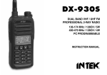
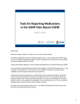
Getting Acquainted
Upper Panel
Front Panel
6
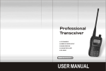
Rear Panel
2, Indicator Light
1,Loudspeaker
(Red light, green light)
3, MIC Connector (RJ45)
4,CHA+(Channel Up)
5, CHA-(Channel Down)
6, LCD display screen
7,VOL+(Volume Up)
8,VOL-(Volume Down)
11, P2 Key
(User defined)
10, P1 Key
(User defined)
12, P3 Key
(User defined)
13,
14,Antenna Connector
9, Menu Key
Power Switch
15,Power Connector
16, Earphone Jack
7
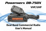
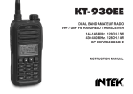
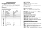
DTMF Microphone Panel
8
1, PTT
Push to Talk
2, MIC
Microphone
3, UP
Up, VOL+
4, DN
Down, VOL-
5, A
Call
6, B
VFO/MR Switch
7, C
A/B mode Switch
8, D
VFO Band Change
9, #
CHA+
10, *
CHA-
9
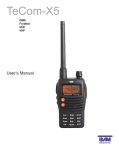
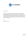
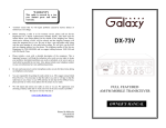
LCD Display
1
Feature
Description
Memory Channel
No.
2
Being A Channel
Switch A/B Key
3
Being B Channel
Switch A/B Key
4
Keyboard Lockout
Press M Key for 2
Seconds
5
VOX Open
Refer to Menu 45
No
Icon
10
Operation Method
----
6
DCS Open
7
CT Open
8
Offset Frequency
10
Wireless
Frequency Open
Channel
scan
disabled
In VFO/MR mode:
Decode Type and
Decode Code refer
to Menu08 and 09,
Encoded Type and
Encoded Code refer
to Menu 10 and 11
The same as above
(DCS)
Refer to Menu 34
and 35
Refer to Page 44
Refer to Menu 39
11
Low Power
Refer to Menu 30
12
High Power
Refer to Menu 30
13
Indicate
Power
strength
when
transmitting, 10
grids for high
power, 5 grids for
small
power.
Indicate
signal
strength
when
receiving.
----
14
Auto Power off
Refer to Menu 01
11
15
Reverse
Frequency
Refer to Menu 33
16
Narrowband
Refer to Menu 50
17
Dual Reception
Refer to Menu 07
18
DTMF
Refer to Menu 06
19
Displayed
frequency value,
channel
names,
menu items, and
other
numbers,
letters or symbols
Information
----
Front Panel Description
Orient the transceiver with the front panel facing you.
Find the RJ-45 microphone jack on the left side of the
front panel. To the right of the microphone jack is a
column of three buttons. From top to bottom, these are
CH+, CH-, and M (Menu). The LCD display is
directly to the right of these three buttons.
Below the LCD display is a row of four buttons. From
left to right, these are P1, P2, P3, and the power
button.
Finally, to the right of the LCD display is a column of
two buttons, labeled VOL+ and VOL-.
12
Basic Operation
Power on/off
button to turn
Once power is connected, press the
the transceiver on. Three ascending tones will sound,
indicating that the transceiver has correctly powered
on. Hold the
key for 2 seconds to turn the
transceiver off.
Turn Volume
Press “VOL+” to raise the volume. Press “VOL-” to
lower the volume. Hold the key to go fast. The volume
is adjusted in 15 steps from 0 (lowest) to 15 (highest).
The default setting is 4.
Select Channel
You can select an operating channel in one of several
ways:
1) Use the programming software to store operating
channels ahead of time. You can then access them
directly in MR mode, using the channel up/down
buttons or the numeric keypad on the microphone.
2) Input frequency values by using the numeric
keypad in VFO mode.
3) Press the “CHA+” or “CHA-” key to select the
13
frequency in VFO mode. Hold the key to go fast
4) Input channel number by using the numeric keypad
to select memory channel in MR mode.
Note: This transceiver has a dual-watch function, you can
switch between A and B channels using the “C” key (A/B
switch key) on the microphone keypad. The A channel can only
operate in MR/CH mode, while the B channel can be set to
either MR/CH or VFO mode. Please refer to page 40-41
regarding the user-defined key function of the A/B switch and
the VFO/MR switch.
In VFO mode, the transceiver will store the most recently used
frequency in each of its supported ranges. To switch quickly
between the transceiver’s supported frequency ranges, press the
key.
Transmitting and receiving
To transmit, press and hold the PTT key of the
microphone and speak normally. Release the PTT key
to stop transmitting.
¤ Please use Low Power whenever possible. If the
distance between you and the other station is
short, low power (5 watts) should be adequate.
Using low power when possible will not only use
less power from your battery or power supply,
but your transmitter will also produce less heat,
increasing the life of your final amplifier.
14
¤
¤
For best voice quality, hold the microphone about
2 IN (5 cm) away from your mouth and speak
normally.
A red LED indicates that the transmitter is active.
Function Menu Operation
To modify settings in the transceiver’s settings menu,
follow these steps:
1) Press the “M” key.
2) a, Use the “CHA+” and “CHA-“ keys, or the
“VOL+” and “VOL-“ keys to select the menu
option you wish to modify. Hold the key to go fast
b, You can also input menu number directly by
using the numeric keypad to select desired menu.
3) Press the “M” key to select the menu for
modification.
4) Use the “CHA+” and “CHA-‘ keys, or the
“VOL+” and “VOL-“ keys to select the desired
value.
5) Press the “M” key to confirm your changes,
6) Repeat steps 2-5 above to modify other menu
options.
7) Finally, when you have made all of your changes,
press any of the front panel keys, except “CHA+”,
“CHA-“, “VOL+”, or “VOL-“, to exit the menu.
15
Auto Power Off(APO): Menu 01
Auto Power Off will automatically turn the
transceiver off after a set length of inactivity. This
function is disabled (off) by default. The Auto Power
Off interval can be set to 10 minutes, 20 minutes, 30
minutes, 40 minutes, 50 minutes, 60 minutes, 90
minutes, 2 hours, 4 hours, 6 hours, 8 hours, 10 hours,
12 hours, 14 hours, or 16 hours. The transceiver
icon when APO function is
displays a
enabled.
APRO (APRO): Menu 02
The audio processing menu allows you to set up the
compander and voice scrambler. This setting is stored
on a per channel basis. Each channel can have a
different processing setting. By default all processing
options are disabled (Off). You can set this menu to
either enable the compander (Comp) or voice
scrambler (Scra).
Busy Channel Lock (BC Lock): Menu 03
When a Channel has the “BC LOCK” function
enabled, the ability to transmit is disabled on that
channel if it is active. You will again be able to
transmit on the channel when the channel is quiet.
This option can be set to “ON” or “OFF”. The default
16
setting is OFF.
Key Beep (Beep): Menu 04
This function determines whether pressing keys on the
transceiver or DTMF microphone sound an audible
confirmation beep when they are pressed. It can be set
to “ON” or “OFF”. This feature is turned on by
default.
Channel Save (CHASave): Menu 05
Users can save custom frequency as memory channel,
so that save time to re-set the frequency parameters.
In VFO mode, enter the frequency you want to save,
press the M key and press “CHA+/CHA-/VOL+/VOL-”
to menu 05 “CHASAVE”, select the channel number
which you want to keep after the screen displayed
"CHASave TO 001", then the frequency is saved.
Up to 199 of your favorite or most commonly used
simplex or repeater channels can be stored in the
transceiver for quick and convenient recall.
In VFO mode, enter the frequency you want to save
by using the numeric keys on the microphone or the
“CHA+” and “CHA-” keys. Once you have tuned to
your desired frequency, press the “M” key, then press
the “CHA+” and “CHA-“, or the “VOL+” and
“VOL-“ keys to select menu 05 “CHASAVE”, and
17
press the “M” key again. Select the channel number
you wish to program. The default is 001. Once you
have selected the channel to program, press the “M”
key again to confirm.
DTMF Function (DTMF): Menu 06
DTMF (Dual Tone Multi Frequency), dual tone
multi-frequency, consists of high-frequency group and
low frequency group, each group contains four
frequencies. A high frequency signal and a low
frequency signal superimposed to form a combined
signal which representing a number. DTMF signaling
has 16 codes, can be set freely. When a radio channel
setting of the DTMF enabled, you can send DTMF
codes by wireless control to achieve individual call,
group call or RX Inhibition, RXTX Inhibition and
other functions.
Dual-Tone Multi-Frequency (DTMF) is a signaling
method in which two tones are combined to create one
of 16 separate codes. These codes represent digits 0-9,
plus *, #, A, B, C, and D. The transceiver can generate
and decode DTMF sequences in order to control other
equipment, remotely control or inhibit other
transceivers, or page individual radio users or groups
of users. Each of the 199 channels can be individually
programmed for DTMF signaling to be enabled or
disabled. Note that if DTMF is disabled on a channel,
18
it can neither be transmitted nor decoded.
Enable Or Disable DTMF Signaling
1, In VFO / MR mode, select a frequency or memory
channel to modify DTMF signaling. Alternatively,
you can enable DTMF signaling in the programming
software.
Note:
a), If the transceiver is in CH mode, you can not enable or
disable DTMF signaling from the transceiver’s front panel. In
CH mode, this setting can only be modified from the
programming software.
b), In MR mode, each memory channel can be independently
set to have DTMF signaling enabled or disabled.
2, Press the “M” key and use the “CHA+” and
“CHA-“ or “VOL+” and “VOL-“ keys to select Menu
06. Press the “M” key to open the menu, and select
“ON” or “OFF” to enable or disable DTMF signaling.
The default setting is ON. Once you have made your
selection, press the “M” key to accept the change,
followed by the
key to exit the menu.
Individual call/ group call
Individual call: Using programming software, set the
transceiver’s individual ID code. This can be any code
of up to 15 characters, using the digits 0-9, *, #, A, B,
19
C, and D. The default transceiver individual call ID
code is 1000.
Group Call: Using a group call character in any part
of a radio calling sequence will call all radios in a
specific calling group. The only radios in the group
that will not automatically respond to a group call are
transceivers which are either set to selective call only
or those which have receive or receive/transmit inhibit
enabled. The group character may be *, #, A, B, C, or
D. The default group character is A.
Consider the following example.
Set 10 transceivers as follows:
Item
Transceiver
1
Transceiver
2
Transceiver
3
Transceiver
4
Transceiver
5
Individual ID
Unite ID
Group ID.
80811
C
Group 1
80812
C
Group 1
80813
C
Group 1
80814
C
Group 1
80815
C
Group 1
20
Transceiver
6
Transceiver
7
Transceiver
8
Transceiver
9
Transceiver
10
80831
C
Group 3
80832
C
Group 3
80833
C
Group 3
80834
C
Group 3
80835
C
Group 3
Send the ID code: 80814 to call "Transceiver 4".
Send the ID code: 80832 to call "Transceiver 7".
Send the ID code: 8081C to call all transceivers in
Subgroup 1.
Send the ID code: 8083C to call all transceivers in
Subgroup 3.
Send the ID code: 808CC to call all transceivers in
Group 1 and Subgroup 3 which are both in Group C.
DTMF code transmission mode:
1, Automatic transmission: Fill in the DTMF call list
in the programming software. In VFO / MR / CH
mode, be sure that DTMF Mode is enabled.
Press the CALL key (A key on the DTMF
microphone). Select an autodial slot from the list.
Press the PTT key to send the selected DTMF
sequence. (Note: Slots 0-9 can be entered directly, or
21
press UP / DOWN keys on the microphone or press
“CHA+/CHA- or VOL+/VOL-”on the transceiver
front panel to select. Slots 10-15 can only be selected
by using the “UP/DOWN” buttons on the microphone
or “CHA+/CHA-“ or “VOL+/VOL-“ keys on the
transceiver front panel.
2, Manual transmission: If the DTMF autodial list is
empty, automatic DTMF transmission is disabled.
However, you can manually enter a sequence of
DTMF tones manually.
Press the “CALL” key twice, then enter your desired
sequence of DTMF tones from the keypad. Finally,
press the PTT key to transmit. You will hear the
DTMF tones transmit if they were properly entered.
Remote RX Inhibition and RXTX Inhibition
RX Inhibition: If RX Inhibit is enabled, the receiver
will remain inactive until it receives the correct RX
Enable code.
RXTX Inhibition: With RX/TX Inhibit enabled, the
transceiver will be unable to receive or transmit until it
receives the correct RX/TX Enable code.
Refer to page 46 for more about RX Inhibition and
RXTX Inhibition.
22
Dual Watch (DW): Menu 07
This setting determines whether the dual watch
feature is enabled or disabled. With dual watch
enabled, the transceiver will monitor two frequencies
periodically. Select Menu 07 to modify this function,
which can be turned ON or OFF. The default is ON.
Decode Type and Decode Code (Menus 08 and 09)
Using Menus 08 and 09, you may determine what will
open the receiver’s squelch. Set the “DecType” option
(Menu 08) to select the squelch mode:
OFF: Any signal on the channel will open the
receiver’s squelch.
CTCSS: Only a signal on the channel containing a
matching CTCSS tone (one of 58 tones) will open the
receiver’s squelch.
NDCS: Only a signal on the channel containing a
matching normal DCS code (one of 107 codes) will
open the receiver’s squelch.
IDCS: Only a signal on the channel containing a
matching inverted DCS code (one of 107 codes) will
open the receiver’s squelch.
After you have selected the decode type in Menu 08,
select the CTCSS or DCS code in Menu 09 from the
following tables. You can press and hold
“CHA+/CHA-/VOL+/VOL-” key to go fast.
23
CTCSS: 56-254.1 Hz (58 groups), NDCS: 107 groups
Normal DCS code. IDCS: 107 groups Invert DCS
code.
CTCSS standard frequency table (58 groups)
56.0
74.4
107.2
156.7
189.9
241.8
57.0
77.0
110.9
159.8
192.8
250.3
58.0
79.7
114.8
162.2
196.6
254.1
59.0
82.5
118.8
165.5
199.5
60.0
85.4
123.0
167.9
203.5
61.0
88.5
127.3
171.3
206.5
62.0
91.5
131.8
173.8
210.7
63.0
94.8
136.5
177.3
218.1
67.0
97.4
141.3
179.9
225.7
69.3
100.0
146.2
183.5
229.1
71.9
103.5
151.4
186.2
233.6
24
DCS Standard Code Table
017
053
125
172
251
315
411
462
565
703
023
054
131
174
252
325
412
464
606
712
025
065
132
205
255
331
413
465
612
723
026
071
134
212
261
332
423
466
624
731
031
072
143
223
263
343
431
503
627
732
032
073
145
225
265
346
432
506
631
734
036
074
152
226
266
351
445
516
632
743
043
114
155
243
271
356
446
523
645
754
047
115
156
244
274
364
452
526
654
050
116
162
245
306
365
454
532
662
051
122
165
246
311
371
455
546
664
Encode Type and Encode Code (Menus 10 and 11)
Similar to the settings for “Decode Type” and “Decode
Code” above, using Menu 10, “EncType” and Menu
11”Enc code”, you may determine the CTCSS or DCS
code that is used on a particular channel. You may
need such a code in order to access a repeater system
25
or other radio users who have CTCSS or DCS squelch
enabled. You may set Menu 10 as follows:
OFF: Disable. The transmitted signal does not send
any CTCSS or DCS codes.
CTCSS: Transmit a specified CTCSS tone (one of 56
tones)
NDCS: Transmit a specified normal DCS code (one of
107 codes).
IDCS: Transmit a specified inverted DCS code (1 of
107 codes)
Use Menu 11 to set the desired CTCSS or DCS tone,
using the same tables as for Menu 09.
FM Radio Function(FM): Menu 12
This transceiver has a built-in FM broadcast receiver.
You may listen to FM radio broadcasts using this
transceiver. To turn the FM broadcast radio on or off.
FM frequency range: 87.5-108MHz.
In VFO / MR / CH mode, press the “M” key, then
press “CHA+/CHA-“ or “VOL+/VOL-” keys to select
Menu 12, then press “M” key to turn on the FM
broadcast radio. To turn off again, follow the same
procedure.
26
Open/Close FM Function
You can set the P1, P2, or P3 key as the shortcut
key to turn the FM radio on or off.
With the FM radio turned on, use “CHA+/CHA-”
keys to select a station, or enter the station’s
frequency directly from the numeric keypad on
the microphone. You can also store your favorite
radio stations using the programming software.
Note: To ensure good FM reception, please connect an antenna
to the transceiver.
FM Scan(FM Scan)): Menu 13
The FM Scan function determines whether the
“CHA+/CHA-“ keys scan for active FM channels or
simply tune the radio in 50 KHz tuning steps. Setting
FM Scan (Menu 14) to ON will increase tuning speed,
as only active FM radio signals will stop tuning.
FM SQL (FM SQL): Menu 14
The FM SQL menu determines the sensitivity of the
FM broadcast scan. The higher this setting, the
stronger a signal must be in order for the scan to stop
on a particular FM broadcast channel. Settings range
from 0 (always on) to 9 (tightest squelch for scan).
The default level is 5.
27
FM DualWatch (FM DW): Menu 13
The FM Dual Watch feature allows you to continue
listening to an FM broadcast station at the same time
as another signal from the transceiver is present. If
this feature is disabled, a signal from the main
transceiver will interrupt FM broadcast radio
reception. In either case, pressing the PTT will
interrupt FM broadcast reception. This feature may be
turned ON or OFF through Menu 13. The default
setting is ON.
Font size (Choose(Font): Menu 16
You can select the font size of the channel display
through this menu. Select “BIG” to show both
channels in a larger font. Choose “SMAL” to have the
active channel in a larger font and the second channel
in a smaller font. The default setting is SMAL.
Note: “BIG” font can only be set if Channel Alias is also set as
active.
Key Lock Function (Keylock): Menu 17
You may lock the transceiver controls by holding the
“M” key for one second. When the lock is enabled,
the symbol appears. Unlock the transceiver controls
by again holding the “M” key for one second.
28
You can choose what controls are locked through
Menu 17 as follows:
KEY: Numeric and function keys, keys on the
microphone and the front panel of transceiver,
key.
excluding the “M” key and the
K + S: KEY + DIAL. Numeric +function keys +
“CHA+/CHA-/VOL+/VOL- excluding the “M” and
keys
PTT: PTT Key.
ALL: KEY + DIAL + PTT excluding “M” key and
key
Default is K + S.
Keypad Function(Keypad): Menu 18
Menu 18 is set depending on which microphone
shipped with your transceiver. If you received the
DTMF microphone, set this menu to ON. Setting to
OFF will not allow you to use the keys on the DTMF
microphone. If you did not receive the DTMF
microphone, for power conservation, we recommend
you set this menu to OFF. The default setting is ON.
Backlight (Lamp): Menu 19
You can set backlight behavior through Menu 19.
Select from the following settings:
OFF: Backlight is disabled
29
KEY: Backlight is active only when a key is pressed.
CONT: Backlight is always enabled. The default
setting is CONT.
Setting Channel Names: (Name): Menus 20 /21/22
Menu 20 determines whether the transceiver allowed
the user-defined channel name displayed or not. If it is
enable, all channel would display user-defined
channel name, if it is disable, all user-defined channel
name would not be displayed.
Menu 21 determines whether a user-defined channel
name will be displayed. Set this option to ON if you
would like to see channel names instead of merely
channel numbers. The default is OFF.
It may be helpful for you to name particular channels
with meaningful labels, such as callsigns, cities, or
channel use. Your channel names can be up to seven
characters long.
You can edit channel names using Menu 22. Access
Menu 22, press P2 to edit the first digit, press
“CHA+/CHA-/VOL+/VOL-” to select the character
desired, then press P2 to confirm and edit next digit,
after edit all digit desired, press P3 key to end edit and
press Menu key to exit. The default label for any
channel is “Name***”. You may use any of the
characters in the following table in your channel
names.
You
can
press
and
hold
30
“CHA+/CHA-/VOL+/VOL-” key to go fast.
Edit Alias valid characters:
A B C
D
E F G H I J
K
L
M
N
O
P
Q
R
S
T
U
V
W
X
Y
e
q
Z
f
r
[
g
s
¥
h
t
]
i
u
^
j
v
k
w
̀
l
x
a
m
y
b
n
z
c
o
{
d
p
│
}
→
←
space
!
"
#
$
%
&
’
(
)
5
*
6
+
7
,
8
9
.
:
/
;
0
<
1
=
2
>
3
?
4
@
Set Opening Display (OpenDIS): Menu 23
You can select what displays when the transceiver
first powers on by using Menu 23. Choose from the
following options:
ALL: Boot displayed as full screen display.
SYS: Boot displayed as system welcome word.
User: Boot display as User-defined word.
You can set the user-defined word in the programming
software.
Time: Boot display as remaining lease time.
The default setting is USER.
31
Custom Keys Set (P1-P3、M Key): Menus 24-29
You can define the shortcut function directly through
software. Default of M short press is to enter the
Menu.
Default of shortcut keys:
P1 Long Press: FM (FM radio)
P1 Short Press: Time (Time display on screen)
P2 Long Press: MOLO (Monitor Lock)
P2 Short Press: Bandchange(Change band)
P3 Long Press: SCAN (scan)
P3 short Press: MUTE (mute)
M Short Press: Enter the menu function
Several keys on the front panel of the transceiver are
user programmable. Each key has two possible
functions, defined in Menus 24 through 29.
Key functions are accessed via a short press (press
and release) or long press (press and hold for 1.5
seconds by default, although this time can be adjusted
in the programming software).
Please refer to Page 37 for details of setting up these
programmable shortcut keys.
While functions for short and long press of Keys P1,
P2, and P3 are defined in Menus 24 through 29, the M
key is a special case. The short press of the M key can
only be defined in the programming software, since its
default behavior is to access the setup menu. The M
32
long press is not user defined, as it locks or unlocks
keys and/or PTT. (See “Keylock”, Menu 17, for
details.
The default functions of the programmable keys are as
follows:
P1 Long Press: FM (FM transceiver)
P1 Short Press: Time (Time display on screen)
P2 Long Press: MOLO (Monitor Lock)
P2 Short Press: Bandchange (Change band
136/245/400 MHz)
P3 Long Press: SCAN (scan)
P3 short Press: MUTE (mute)
M Short Press: Enter the menu function
High/Low Power Set (Power): Menu 30
You may select your desired transmit power level
from Menu 30. For communication with nearby
stations, we recommend that you use low power. This
will produce less heat and prolong the useful life of
the final amplifier. For stations that are more distant,
you should use high power for improved
communication clarity. High power is the default
setting.
PTT ID (PTT ID): Menu 31
PTT ID allows you to send a code that identifies your
33
specific transceiver. The PTT ID code is defined in the
programming software; the default ID is “123”.
You can also set whether PTT ID’s are spoken or
displayed. If voice is selected, ID’s of up to five digits
will be spoken. However, up to 14 digit ID’s can be
displayed if voice ID’s are disabled.
Each channel stores whether the PTT ID is enabled.
To enable PTT ID:
In VFO / MR mode, choose the frequency or channel
on which you would like to enable the PTT ID.
Set Menu 31 to ON if you would like to enable the
PTT ID, or OFF to disable it.
Note:
a) In CH Mode, you may not modify this setting.
b) In MR mode, each memory channel can be
individually programmed to enable or disable PTT
ID.
You may also use the programming software to enable
or disable PTT ID for any channel.
The PTT ID can be sent:
1. At the beginning of the transmission: The ID is sent
immediately when the PTT key is pressed.
2. At the end of the transmission: the PTT ID is sent
when the PTT key is released.
3. Both: the PTT ID is sent both when the PTT key is
pressed and again when it is released.
34
ROGER(ROGER): Menu 32
The transceiver can send a “Roger beep” to mark the
end of a transmission. Select Menu 32, and select
“ON” to enable this feature, or “OFF” to disable it.
The default setting is OFF.
REVERSE (REVERSE): Menu 33
The Reverse feature can only be enabled if Offset
Frequency and RPT Type, Menus 34 and 35, are also
set. The Reverse function swaps the receive and
transmit frequencies so that you can hear another
transceiver’s calls directly rather than through a
repeater. This would be useful in order to determine
whether you can establish direct contact with a nearby
station, freeing up the repeater for other uses.
To set the Reverse function, set Menu 33 to “ON”. To
return to normal operation, set Menu 33 to “OFF”.
Offset Frequency (RPT SET/RPT TYPE): Menus
34 and 35
You can set a channel to use different receive and
transmit frequencies. This is most useful for operating
through a repeater, which receives on one frequency
and then retransmits on another frequency from a
higher antenna. This effectively provides systems
35
using the repeater with greater communication range
than they would achieve alone.
Setting these separate frequencies is accomplished by
setting Menus 34 and 35. First, you will need to set
the offset amount, which is the difference between the
receive and transmit frequencies. The transceiver can
accept offset values from 0.000 to 399.995 MHz.
In VFO Mode, select Menu 34. Enter the offset value
using the number keys on the DTMF microphone, or
by using the “CHA+/CHA-“ or “VOL+/VOL-“ keys.
Select the offset direction using Menu 35. Using the
“CHA+/CHA-“ or “VOL+/VOL-“ keys, select
“RPT+” (positive offset, the transmit frequency is
higher than the receive frequency), “RPT-” (the
transmit frequency is lower than the receive
frequency), or “SING” (no offset, only a single
frequency is used).
For example: In VFO mode, enter a frequency such as
450MHz, and set the offset to 5MHz. If RPT Type is
“+RPT”, then the receive frequency is 450MHz, and
the transmit frequency is 455MHz; if RPT Type is
“–RPT”, then the receive frequency is 450MHz, and
the transmit frequency is 445MHz; if RPT Type is
“SING”, receive and transmit frequency are both
450MHz.
Note: Offset frequency setting is only available in VFO mode.
It cannot be set in already programmed memory channels.
36
When using the programming software, you must specify both
receive and transmit frequencies directly.
Save Battery (SaveBat): Menu 36
Battery Save mode lowers current consumption by
putting the receiver in a low power “sleep” mode
periodically during quiet periods with no received
signals. Set Menu 36 ON to enable this function, or
OFF to disable it. The default setting is ON.
Scan (SCAN): Menus 37, 38, and 39
Scan mode allows you to monitor several channels
more efficiently. Channels are scanned until activity is
detected on a channel. Depending on the scan mode,
scanning may continue after a specific length of time,
or it will only continue when the channel is inactive.
Scan Mode: Select the scan mode in Menu 38. There
are two modes:
Time operated (TO): Scanning stops when an
active channel is encountered. The scan will
pause for five seconds, then scanning will
continue, even if the channel is still active.
Carrier operated (CO): Scanning stops when an
active channel is encountered. Scanning resumes
after two seconds of channel inactivity.
The default setting is “TO”.
37
Note: Press any key except “UP”, “DOWN”, “CHA+/CHA-“,
or “VOL+/VOL-“ to stop scanning.
Scan Type: You may choose two different scanning
modes:
VFO frequency scan: All frequencies on the band
will be scanned.
In VFO mode, select Menu 37 and press M key
to start scanning. The scan will begin at the
current frequency and continue up the band. To
reverse the scan direction, press the “DOWN”
key, the “CHA- “key, or the “VOL-“ key. Scan up
the band again by using the “UP” key, the
“VOL+” key, or the “CHA+” key. Press any other
key to stop scanning.
MR/CH scan: Scan only programmed memory
channels in this mode. From MR/CH mode,
select Menu 37, and press the “M” key to start
the scan. Scanning begins on the current channel
and scans up to higher channel numbers. To
reverse the scan direction, press the “DOWN”
key, the “CHA-” key, or the “VOL-“ key. Scan up
the band again by using the “UP” key, the
“VOL+” key, or the “CHA+” key. Press any other
key to stop scanning.
Note:
1.
Each memory channel can be set to be blocked
from scan through Menu 39. If Scan Add is
38
2.
3.
disabled on a channel, that channel will be skipped
during MR/CH scans. A channel’s scan status will
be indicated on the transceiver’s display.
MR/CH Scan is only available if two or more
channels are programmed with Scan Add enabled.
Scan is only effective if the squelch is closed.
Squelch Level (SQL): Menu 40
The squelch circuit allows you to only hear desired
signals. If a strong enough signal is not present, the
squelch circuit is closed, and you will hear no
background noise. Higher levels of the Squelch level
setting require stronger signals to open the squelch
circuit. Set the squelch level to one appropriate to the
amount of RF noise in your environment. A squelch
setting that is too high may cause you to miss
receiving a weaker signal, while too low a setting may
cause you to hear more noise than you might want.
Set the Squelch Level using Menu 40. There are nine
levels of squelch setting; the default level is 2.
Step (Step): Menu 41
Step is the value in which the operating frequency
increases or decreases with presses of the “Up”,
“Down”, or “CHA+/CHA-“ keys in VFO mode.
Select the Step in Menu 41. Valid step sizes are 2.5, 5,
6.25, 10, 12.5, and 25 KHz. The default is 25 KHz.
39
Tail Elimination (Tail): Menu 42
The Tail elimination function eliminates the burst of
background noise encountered at the end of a
transmission. . Set Menu 42 to ON if you would like
to enable this feature, or OFF to disable it. The default
is ON.
Talk Around (Talk): Menu 43
When the Talk around feature is enabled, the transmit
and receive frequency and signaling mode are the
same. This would be useful if two stations who are
close together wish to temporarily use the output
frequency of a repeater. Turn Menu 43 ON to enable
this feature. The default is OFF.
Time out timer(TOT): Menu 44
You may use Menu 44 to specify a time-out timer for
the transmitter. Setting such a timer would prevent
accidental, lengthy transmissions where the
transmitter does not properly unkey(a stuck PTT key,
for instance). Not only could such transmissions be
disruptive to other communications, they could
damage the transmitter. Select Menu 44, and set the
Time-Out Timer to OFF, or in 10-second intervals of
up to 120 seconds. The default setting is 30 seconds.
40
TX Stop (TXStop): Menu 45
The TXStop function disables the transmitter when it
is enabled. If TXStop is enabled, pressing the PTT key
will issue an audible alert tone, indicating that you are
unable to transmit. Select Menu 45, and set it to ON if
you would like to enable this feature. The default
setting is off.
VOX (VOX): Menus 46-49
VOX, or Voice-Operated Transmit, allows you to
transmit by simply speaking into the microphone.
With VOX enabled, you won’t need to press the PTT
key to enable the transmitter. Use Menu 46 to turn
VOX ON or OFF. The default is OFF.
VOX S (Sensitivity):
VOX Sensitivity determines the level of sound that is
needed for the VOX to key the transmitter. You should
experiment with VOX Sensitivity to find a level that
is appropriate to your voice but does not trigger on the
presence of too much other background noise. Set Vox
S using Menu 47. There are eight possible levels. The
default level is 3.
VOX D(Delay):
VOX Delay determines the delay to stop transmitting
after you finish speaking. Set the VOX Delay in Menu
48. Too short a delay will cause the transmitter to
41
unkey too frequently. Delay can be set from 1 to 4
seconds; the default setting is 3 seconds.
VXB (VOX inhibited when receiving):
Set Menu 49 to ON if you do not want VOX active
while the receiver is active. To avoid the receiver
keying the VOX by mistake, it is probably a good idea
to leave this setting at its default ON state.
Wide and Narrow Bandwidth Set (WidNar): Menu
50
You can set the channel bandwidth to “WIDE” or
“Narrow” using Menu 50. Set this according to your
country or radio service regulations. The default
setting is WIDE.
User-defined Keys Menu
As previously mentioned the P1, P2, P3, and Menu
keys are user programmable. While the short press of
the M key can only be changed in the programming
software, the P1, P2, and P3 keys can be programmed
using Menus 24-29.
Each of these keys has two programmable functions,
accessed by a short press (press and release) or a long
press (Press and hold for 1.5 seconds). Each of these
functions is set in one of the programmable key
menus.
Note: If you would like to change the hold time for Long Press,
you may do so using the programming software.
42
You may set any of the programmable keys to perform
the following functions:
OFF
If a shortcut key is disabled, it is not usable unless
Wireless Change Frequency is enabled. Please refer to
Page 44 for details.
FM(FM)
Setting a shortcut to FM toggles the FM broadcast
radio on or off.
Band change(Bandchange)
In VFO Mode, the Band Change button switches
between the last used frequencies on 136 MHz, 245
MHz, or 400 MHz.
Time of system(Time)
Setting a shortcut to TIME will display the system
time. There is a built-in button cell (CR2032) which
supply power to continue timing system time when
the radio power off. Normally the button cell can use
several years, but you can change a new CR2032
when it is used out.
Note: The system time can only be set though program
software.
43
Monitor Momentary(MONI)
Setting a shortcut key to MONI will allow you to
temporarily open the receiver squelch, in order to hear
a weak signal that cannot break through at the current
squelch setting. Pressing MONI will open the
receiver’s squelch, and releasing will close it again.
Note: MONI can only be set as Long press.
Monitor Lock(MOLO)
Setting MOLO will open the squelch to allow you to
listen for weaker signals. Pressing the MOLO shortcut
will open the squelch, while pressing it again will
close the squelch again. If MOLO stays active for
more than 10 seconds, squelch will automatically
close.
SQ OFF Momentary(SQM)
If the SQM shortcut is enabled, pressing it will disable
any CTCSS or DCS squelch, allowing any signal to
activate the receiver. Pressing this key will issue an
audible alert indicating the feature is active. Pressing
the key a second time will sound a different alert to
indicate that the receiver is in its normal state.
Note: SQM can only be set as Long press.
44
Mute(MUTE)
When the Mute shortcut is enabled, pressing the Mute
key will disable audio from the receiver’s speaker.
Press the key again to unmute the speaker.
Scan(SCAN)
Pressing the LOW shortcut will toggle the power level
between HIGH and LOW power.
High/Low Power(LOW)
Pressing the LOW shortcut will toggle the power level
between HIGH and LOW power.
Emergency(EMG)
The EMG key will sound an emergency alarm. When
this alarm sounds, the indicator LED’s will alternate
between flashing red and green and “TX STOP” will
display on the screen. This mode will remain in force
until the PTT is pressed or the transceiver is powered
down.
V/M Mode Switch(V/M)
The VM shortcut will toggle the B operation between
VFO and MR mode.
45
DTMF Function(DTMF)
The DTMF shortcut will turn DTMF Mode on or off.
Call(Call)
The CALL shortcut will toggle the CALL function on
and off.
Transmit 1750Hz(1750Hz)
The 1750Hz shortcut will transmit a 1750Hz burst
tone when pressed.
A/B Mode Switch(A/B)
The A/B shortcut will toggle between the A and B
channel.
Talk Around(Talk)
The Talk Around shortcut turns Talk Around mode on
or off.
Reverse Frequency(Reverse)
The Reverse shortcut enables or disables Reverse
frequency mode.
46
Reset Menu
All Reset
All Reset resets the transceiver to all factory settings,
leaving only the DTMF dial list untouched.)
key to turn the
To perform an All Reset, press the
transceiver on. When the welcome screen is displayed,
hold the M key for two seconds. The screen will
display “Menu 0/ALL RES? ". Press the M key again
and the screen will display “RESET”. Press the M key
a third time, and the screen will display “Waiting”.
When the transceiver restarts, the reset is complete.
Note: You may cancel the reset by pressing any key
other than the “M” key when the “Reset?” prompt
appears.
Function Reset
Function Reset will reset the transceiver to factory
default settings, leaving memory channels and the
DTMF list intact.
key to turn
To perform a Function Reset, press the
the transceiver on. When the welcome screen is
displayed, hold the M key for two seconds. The screen
will display “Menu 0/ALL RES? ". Use the
microphone’s
UP/Down
keys,
or
the
47
“CHA+/CHA-“ or “VOL+/VOL-“ keys to select
“Menu 1 FUN RES”. Press the M key again and the
screen will display “RESET”. Press the M key a third
time, and the screen will display “Waiting”. When the
transceiver restarts, the reset is complete. Note: You
may cancel the reset by pressing any key other than
the “M” key when the “Reset?” prompt appears.
Programming Operation
Lease Function
The Lease function can be set to limit how long a
transceiver can be used. When the Lease Time expires,
the transceiver will no longer operate, and the
indicator LED will light continuously red. At this
point, the user may only turn the transceiver power off.
This function can only be reset with programming
software.
Remaining time: You can set the transceiver to display
the time remaining for the transceiver lease. If the
Lease function is enabled using the programming
software, the startup display can be set to display the
remaining lease time.
Lease Time: You may set the transceiver Lease Time
through the programming software. The valid Lease
Time range is from 1 minute to 255 days 24 hours,
and 59 minutes.
48
Wireless Change Frequency
Wireless Frequency Change is a feature that allows
the transceivers to be programmed with new
frequency information remotely. In other words, one
master transceiver can program several deployed
transceivers in the field by sending the appropriate
commands over the air.
Consider the following example:
A team bought 10 transceivers. One is used at the
home office, while the other nine are installed in
company cars. The home office needs to add a new
communications channel to all deployed radios. Thus,
the staff at the home office may use Wireless
Frequency Change to program all the radios remotely
without having to do them one at a time and without
having to recall them back to the home office for
programming.
Refer to details as following:
1) First, all transceivers should have Wireless
Frequency Change enabled on all 10 transceivers
ahead of time. This is accomplished using the
programming software. Additionally, set a 1-15
digit activation code using DTMF digits 0-9 plus *,
#, A, B, C, and D.
2) Program one of the programmable shortcut keys to
OFF, so that it can be used to access the Wireless
49
Frequency Change function.
3) The transceiver at the home office should be
programmed as the “master” transceiver. It should
also have a DTMF microphone.
4) The new channel should be programmed into one
of the master transceiver’s 199 channels. For our
example, we’ll program it into Channel 03.
5) When all transceivers are prepared for the changes,
the change can be accomplished manually or
automatically:
a), Manually change frequency: Alert the other nine
transceivers that a frequency change is ready to be
programmed. The operators of those nine
transceivers would press the shortcut key to enable
the transfer. An icon“ ” will appear acknowledging
that the transceiver is ready for programming. The
master radio would initiate the change using the
instructions in Step 6 below. Once programming is
complete, the icon“ ” will disappear. If it does not
disappear, programming was not successful. Once
programming is successful, the remote users can
switch to the newly programmed channel.
b), Automatically changing frequency: Alert the other
nine transceivers that a frequency change is ready to
be programmed. The master transceiver then sends
the Wireless Frequency Change Enable code. When
this is received, an icon “ ” will appear to
50
acknowledge the remote transceivers are ready for
programming. The master radio would then initiate
the change using the instructions in Step 6 below.
Once programming is complete, the icon “ ” will
disappear. If it does not disappear, programming
was not successful. Once programming is
successful, the remote users can switch to the newly
programmed channel.
6) Changing operation: On the master transceiver,
press the Call key (“A” on the DTMF microphone).
“Send 01” appears on the screen. Use the
“CHA+/CHA-“ or “VOL+/VOL-“ keys to select
the channel you wish to program, such as Channel
003, then press the PTT key. Press the “A” key
again. This will display “Send 03”. Press the PTT
to send the second programming code. If the icon
“ ” disappears, programming was successful.
RX Inhibit/RXTX Inhibit
RX Inhibition: When RX Inhibit is enabled, the
receiver will be inactive until the correct RX Enable
code is received. While the transceiver is in RX
Inhibit mode, pressing the PTT key will also produce
an error tone.
RXTX Inhibition: When RX/TX Inhibit is enabled,
the transceiver will remain completely inactive; it will
51
neither receive nor transmit until the correct RX/TX
Enable code is received. If you attempt to transmit
while RX/TX Inhibit is in force, the transceiver will
not indicate transmission, and it will produce an error
tone.
RX inhibit and RXTX inhibit And Reactivate
Codes: These codes are up to 15 characters long,
using 0-9, A-D, * and #.
To activate RX Inhibit or RX/TX Inhibit, use the
programming software to enable the appropriate
settings and assign the appropriate Inhibit and
Reactivate codes. You can then send the Inhibit or
Activate codes using another transceiver that has
DTMF capability.
Note: If “Activation Enable” hasn’t been checked, the
transceiver cannot be activated over the air with a reactivation
code. In this case, it can only be reactivated through the
programming software.
Setting Transmission Limits Per Minute
To prevent users from transmitting too often and
potentially disrupting communications, you can limit
the number of transmissions allowed during one
minute period. Set this from 0 (No limit) to 255 in the
programming software. If a limit is set and that limit
is exceeded, the transmitter will issue an error tone
and will not transmit until the timer resets.
52
Maintenance
Base Knowledge
This transceiver has been strictly and carefully
calibrated and tested at the factory to ensure that it
meets our stated specifications. Please refer any
service issues to authorized repair facilities. Any
tampering, user performed maintenance or adjustment
of the transceiver will void your warranty. Please refer
any service or maintenance concerns to authorized
dealer.
Cleaning and Maintenance
1) Handle this equipment with care. Do not carry the
transceiver by its power cable, microphone, or
antenna.
2) Use a soft, clean, dry cloth to clean the transceiver.
3) When storing the transceiver, avoid temperature
extremes of heat or cold. Extreme temperatures may
shorten the life of the transceiver.
4) After prolonged use, the transceiver may require
cleaning. Use only mild detergents. Do not use any
corrosive or harsh chemical cleaners. Using alcohol,
oil or spray chemical agents may damage the
transceiver casing.
53
5) Please use only approved antennas. Unauthorized
antennas or modified accessories could damage the
transceiver or violate regulations governing RF
devices.
6) Please back up all settings and programmed data
from your transceiver before sending it in for repair.
7) If your transceiver is defective or develops a
problem, please send it only to authorized service
center. Please contact your local dealer for assistance.
We strived to write content of the manual accurately and
completely, but it might still possible has existence of errors
and omissions. We do not assume any responsibility. We keep
right to change product design and specifications at any time.
As technology developing, design and product specifications
are subject to change without notice.
54
Specification
Band
VHF/UHF Dual Band
TX Frequency
400~470MHz/136~174MHz
RX Frequency
400~520MHz/136~174MHz/
200-260MHz/87.5-108MHz
Channel Capacity
199
Output Power
4W/10W
Operation Mode
Half-Duplex
Dimension
(L*W*H)
120×90×40mm
Weight
315g
Modulation
Limitation
≤±5KHz
Spurious Radiation
60dB
TX Current
1A/1.8A
Frequency Stability
±2.5PPM
Rx Sensitivity
<0.18µV
Modulation Type
F3E
Audio Power
≥400mW
Standby Current
78mA(Power Saving mode is 30mA)
Rated Voltage
13.8V
55
56