1
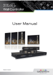
VSC-VPLEX4 VideoPlex4 Video Wall Controller Display standard single- or dual-link DVI input across four output monitors. BLACK BOX ® Each output can be driven as DVI or analog RGB, and can represent an arbitrary crop region of the original input image. Customer Support Information Order toll-free in the U.S.: Call 877-877-BBOX (outside U.S. call 724-746-5500) FREE technical support 24 hours a day, 7 days a week: Call 724-746-5500 or fax 724-746-0746 Mailing address: Black Box Corporation, 1000 Park Drive, Lawrence, PA 15055-1018 Web site: www.blackbox.com • E-mail: [email protected] Trademarks Used in this Manual Trademarks Used in this Manual Black Box and the Double Diamond logo are registered trademarks of BB Technologies, Inc. UL is a registered trademark of Underwriters Laboratories. Windows is a registered trademark of Microsoft Corporation. Any other trademarks mentioned in this manual are acknowledged to be the property of the trademark owners. Disclaimer: Black Box Network Services shall not be liable for damages of any kind, including, but not limited to, punitive, consequential or cost of cover damages, resulting from any errors in the production information or specifications set forth in this document and Black Box Network Services may revise this document at any time without notice. We‘re here to help! If you have any questions about your application or our products, contact Black Box Tech Support at 724-746-5500 or go to blackbox.com and click on “Talk to Black Box.” You’ll be live with one of our technical experts in less than 30 seconds. Page 2 724-746-5500 | blackbox.com FCC and IC RFI Statements Federal Communications Commission and Industry Canada Radio Frequency Interference Statements This equipment generates, uses, and can radiate radio-frequency energy, and if not installed and used properly, that is, in strict accordance with the manufacturer’s instructions, may cause interference to radio communication. It has been tested and found to comply with the limits for a Class A computing device in accordance with the specifications in Subpart B of Part 15 of FCC rules, which are designed to provide reasonable protection against such interference when the equipment is operated in a commercial environment. Operation of this equipment in a residential area is likely to cause interference, in which case the user at his own expense will be required to take whatever measures may be necessary to correct the interference. Changes or modifications not expressly approved by the party responsible for compliance could void the user’s authority to operate the equipment. This digital apparatus does not exceed the Class A limits for radio noise emission from digital apparatus set out in the Radio Interference Regulation of Industry Canada. Le présent appareil numérique n’émet pas de bruits radioélectriques dépassant les limites applicables aux appareils numériques de la classe A prescrites dans le Règlement sur le brouillage radioélectrique publié par Industrie Canada. 724-746-5500 | blackbox.com Page 3 NOM Statement Instrucciones de Seguridad (Normas Oficiales Mexicanas Electrical Safety Statement) 1. T odas las instrucciones de seguridad y operación deberán ser leídas antes de que el aparato eléctrico sea operado. 2. Las instrucciones de seguridad y operación deberán ser guardadas para referencia futura. 3. Todas las advertencias en el aparato eléctrico y en sus instrucciones de operación deben ser respetadas. 4. T odas las instrucciones de operación y uso deben ser seguidas. 5. E l aparato eléctrico no deberá ser usado cerca del agua—por ejemplo, cerca de la tina de baño, lavabo, sótano mojado o cerca de una alberca, etc. 6. E l aparato eléctrico debe ser usado únicamente con carritos o pedestales que sean recomendados por el fabricante. 7. El aparato eléctrico debe ser montado a la pared o al techo sólo como sea recomendado por el fabricante. 8. S ervicio—El usuario no debe intentar dar servicio al equipo eléctrico más allá a lo descrito en las instrucciones de operación. Todo otro servicio deberá ser referido a personal de servicio calificado. 9. El aparato eléctrico debe ser situado de tal manera que su posición no interfiera su uso. La colocación del aparato eléctrico sobre una cama, sofá, alfombra o superficie similar puede bloquea la ventilación, no se debe colocar en libreros o gabinetes que impidan el flujo de aire por los orificios de ventilación. 10. E l equipo eléctrico deber ser situado fuera del alcance de fuentes de calor como radiadores, registros de calor, estufas u otros aparatos (incluyendo amplificadores) que producen calor. 11. E l aparato eléctrico deberá ser connectado a una fuente de poder sólo del tipo descrito en el instructivo de operación, o como se indique en el aparato. 12. P recaución debe ser tomada de tal manera que la tierra fisica y la polarización del equipo no sea eliminada. 13. L os cables de la fuente de poder deben ser guiados de tal manera que no sean pisados ni pellizcados por objetos colocados sobre o contra ellos, poniendo particular atención a los contactos y receptáculos donde salen del aparato. 14. El equipo eléctrico debe ser limpiado únicamente de acuerdo a las recomendaciones del fabricante. 15. E n caso de existir, una antena externa deberá ser localizada lejos de las lineas de energia. 16. El cable de corriente deberá ser desconectado del cuando el equipo no sea usado por un largo periodo de tiempo. 17. Cuidado debe ser tomado de tal manera que objectos liquidos no sean derramados sobre la cubierta u orificios de ventilación. 18. S ervicio por personal calificado deberá ser provisto cuando: A: El cable de poder o el contacto ha sido dañado; u B: Objectos han caído o líquido ha sido derramado dentro del aparato; o C: El aparato ha sido expuesto a la lluvia; o D: El aparato parece no operar normalmente o muestra un cambio en su desempeño; o E: El aparato ha sido tirado o su cubierta ha sido dañada. Page 4 724-746-5500 | blackbox.com Safety Instructions Safety Instructions To prevent damage to your VideoPlex4 or injury to personnel operating the equipment, read the following safety precautions prior to operation. These instructions should be made available to all those who will use and operate the VideoPlex4. Power Supply All VideoPlex4s require a power supply. This power supply must be disconnected when equipment is being upgraded or relocated. Cables Do not expose cables to any liquids; doing so may cause a short circuit that could damage the equipment. Do not place heavy objects on top of any cables, because this can cause damage and possibly lead to exposed live wires. Ventilation All computer equipment should be located in a well-ventilated area. All ventilation holes on the unit casing must be kept clear of any obstruction at all times. Failure to do so will result in the system overheating and damaging your equipment. Working Environment Locate the equipment in an environment free from dust, moisture, and extreme changes in temperature. Place the VideoPlex4 on a stable and solid work surface. Do not place liquids (hot/cold drinks, etc.) near the equipment because spills could cause serious damage. Gas/Flammable Liquids Never use electronic equipment in the presence of gas or any flammable liquid; doing so could result in an explosion or serious fire. Smoke/Unusual Smells If you notice smoke or unusual smells being emitted from your computer, turn off and unplug the system from the power supply. Then pass the system to a qualified technician for inspection. Continued operation could result in personal injury and damage to property. Maintenance Maintenance should only be carried out by competent technicians. Any VideoPlex4s that are damaged should be returned to Black Box for repair using Black Box RMA procedures. Disposal At the end of life, all VideoPlex4s should be disposed of as local laws and regulations dictate. 724-746-5500 | blackbox.com Page 5 Table of Contents Table of Contents 1. Specifications................................................................................................................................................................ 7 2. Overview ................................................................................................................................................................... 8 2.1 Introduction.......................................................................................................................................................... 8 2.2 Configuration Examples....................................................................................................................................... 8 2.3 What’s Included................................................................................................................................................. 12 2.4 Hardware Description......................................................................................................................................... 13 2.4.1 Front Panel............................................................................................................................................... 13 2.4.2 Back Panel................................................................................................................................................ 14 3. Setting Up the VideoPlex4.......................................................................................................................................... 15 4. Configuring the VideoPlex4........................................................................................................................................ 16 4.1 Factory Default Settings..................................................................................................................................... 16 4.2 Configuring DVI Input Resolution....................................................................................................................... 16 4.3 Monitor Outputs................................................................................................................................................ 16 4.4 Selecting the Regions to be Displayed................................................................................................................ 16 5. Operating Instructions................................................................................................................................................ 18 5.1 DVI Input............................................................................................................................................................ 18 5.2 Output............................................................................................................................................................... 18 5.3 Configuring the VideoPlex4................................................................................................................................ 18 5.4 Frame-Lock......................................................................................................................................................... 18 6. VideoPlex4 Control Application.................................................................................................................................. 19 6.1 Application Installation....................................................................................................................................... 19 6.2 Running the VideoPlex4 Control Application...................................................................................................... 19 6.3 Connection Diagram.......................................................................................................................................... 20 6.4 Device.................................................................................................................................................................. 20 6.5 DVI-D Input........................................................................................................................................................ 20 6.6 Input Capture Regions........................................................................................................................................ 23 6.7 Predefined Regions............................................................................................................................................. 24 6.8 Monitor Outputs................................................................................................................................................ 24 Page 6 724-746-5500 | blackbox.com Chapter 1: Specifications 1. Specifications Technical Specifications Approvals FCC, TUV, CE, UL®, CSA, RoHS, WEEE Arbitrary Upscaling Up to 64 X non-integer scale factors allowed Cooling This unit contains a cooling fan. CAUTION: The input and output vents should not be restricted. Dual-Link DVI Capture Up to 330 Mpixels/s Efficiency Level IV Heat Dissipation (Voltage x Nominal Current) x 3.41 = BTU/hr. Input Surface 4K x 4K maximum Leads Supported DVI-D (Dual-Link on input only) Operating System Support All known operating systems; All known hardware that supports/follows the DVI spec Resolution Up to 2.5 Mpixels/s USB Support USB 2.0, full-speed (12 Mbps) operation; Firmware support: Updates supported via USB Interface (1) Dual-link DVI capture; (4) Single-link DVI Connectors Input: (1) DVI-D female; Output: (4) DVI-I female; Power: (1) 3-pin power female; (1) USB Type B female; (2) Sync ports (unused) Indicators (3) LEDs: (1) Power, (1) Input, (1) Status Environmental Temperature Tolerance: Operating: 32 to 96° F (0 to 35° C); Humidity: Operating: 90%, noncondensing; Altitude (Maximum): NEED SPEC ft. (m) Power Input Voltage/Volts: 100–240 VAC; Input Current/Amps: 0.8 A; Output Voltage/Volts: 5 VDC; Power Consumption/Watts: 18 W; Power Supply Cord Length: 3 ft. (0.9 m) Dimensions 1.75" H x 9.25" W x 6.9" D (4.4 x 23.5 x 17.5 cm) 724-746-5500 | blackbox.com Page 7 Chapter 2: Overview 2. Overview 2.1 Introduction The VideoPlex4 is a standalone display wall controller that accepts a standard single- or dual-link DVI input and can flexibly display this across four output monitors. Each output can be driven as DVI or analog RGB, and can represent an arbitrary crop region of the original input image. The output resolution and frame rate do not need to be related to that of the input, because the VideoPlex4 will optionally upscale and frame-rate convert each cropped region independently. However, if the VideoPlex4 detects that frame rates identically match, it will automatically frame-lock all outputs and, if possible, frame-lock these to the input signal. Additionally, each output can be independently mirrored or rotated through 90°, 180°, or 270° to support creative mixes of landscape and portrait monitors. 2.2 Configuration Examples On the next few pages are just a few examples of what can be achieved with the VideoPlex4. The examples are not definitive and users are encouraged to experiment with different display configurations. Figure 2-1. Duplicate the input signal x 4 and display each duplicate on separate screens. Page 8 724-746-5500 | blackbox.com Chapter 2: Overview Figure 2-2. Divide the input signal into quadrants and display each quarter on separate displays with optional frame rate conversion (in this case 30 to 60 Hz). You can adjust crop regions to compensate for monitor bezel. 724-746-5500 | blackbox.com Page 9 Chapter 2: Overview Figure 2-3. Duplicate the input signal x2 and display one output on a single landscape display and divide the second output into thirds, rotate to portrait, upscale, and split between three displays. Figure 2-4. Crop input signal, upscale specific areas, and display on four separate screens. Page 10 724-746-5500 | blackbox.com Chapter 2: Overview Figure 2-5. Crop the input signal into VideoPlex4 and display x2 quarters landscape and x2 quarters portrait. 724-746-5500 | blackbox.com Page 11 Chapter 2: Overview Figure 2-6. Crop the input signal, rotate through 90º, 180º, or 270º; display in landscape and portrait. Arbitrary crop regions can allow the monitors to be artistically arranged, but maintain an undistorted image. 2.3 What’s Included Your package should contain the following items. If anything is missing or damaged, contact Black Box Technical Support at 724-746-5500 or [email protected]. • VideoPlex4 Video Wall Controller • 100–240-VAC, 5-VDC, 18-W universal power adapter • USB 2.0 cable Type A to Type B • VideoPlex4 DVD containing configuration application and this user manual NOTE: We recommend that you do not discard the packing box until you are completely satisfied with the VideoPlex4 and it is fully installed and working correctly. We also recommend that you note the serial number of the controller in a prominent place before you connect it to the computer. You will be asked to provide this serial number if you need to contact our Technical Support department. The serial number is displayed on the VideoPlex4 and the box label. Page 12 724-746-5500 | blackbox.com Chapter 2: Overview Fitting the VideoPlex4 PSU Blades Push to release blade Figure 2-7. PSU blades. Select the appropriate blade for use, place the top edge of the blade into the recess of the PSU and then slide upwards ensuring the release catch clicks firmly into place and secures the blade inside the recess. To remove the blade, press the release catch down fully and pull the blade away from the PSU recess. The PSU is shipped fitted with the UK blade. 2.4 Hardware Description 2.4.1 Front Panel 1 2 3 Figure 2-8. Front panel. Table 2-1. Front-panel components. Number Indicator Description 1 (1) Power LED Lights when the VideoPlex4 is connected to the power supply. 2 (1) Input LED Lights when a valid DVI source is connected. 3 (1) Status LED Lights steady on when the VideoPlex4 is operating normally. Flashing when the unit is operating over the normal operating temperature. Make sure that the input fan vent is not blocked. Off when the settings configured in the VideoPlex4 application no longer match the input. This is normally the result of a change of input. The VideoPlex4 will compensate for the settings and reconfigure itself to display as near to the settings as possible. The output will still be displayed, but not necessarily as expected. 724-746-5500 | blackbox.com Page 13 Chapter 2: Overview NOTE: When the VideoPlex4 is connected to a PC by a USB cable and the VideoPlex4 control application is active, all three lights flash to identify which unit is being controlled. 2.4.2 Back Panel 1 1 4 2 4 4 3 4 5 Figure 2-9. Rear panel. Table 2-2. Back-panel components. Number Indicator Description 1 Sync Sockets The Sync sockets are provided for future genlock enhancements. Leave them unconnected. 2 USB Socket The USB socket is used to connect the VideoPlex4 to a PC via a USB connection using the supplied USB Type A to Type B cable. Configuration of the VideoPlex4 is programmable via an application utility, allowing easy control of cropping, scaling, rotation, and gaps. 3 DVI-D Input Socket The DVI-D Input socket is used to connect the DVI input source to the VideoPlex4. The VideoPlex4 supports dual-link DVI, single-link DVI, and also HDMI (not HDCP compliant) via the optional DVI/HDMI adapter (part number FA790). 4 DVI-I Output Socket The four DVI-I Out sockets are used to connect the VideoPlex4 to the output monitors. The VideoPlex4 supports both DVI and analog RGB monitors. 5 Power The Power socket is where the supplied power source connects to the VideoPlex4. The power LED on the front of the VideoPlex4 illuminates when a power supply is connected. Page 14 724-746-5500 | blackbox.com Chapter 3: Setting Up the VideoPlex4 3. Setting Up the VideoPlex4 • Make sure the power supply for the DVI source is disconnected. • Connect the cable from the DVI source to the input socket on the rear of the VideoPlex4. • Connect the four displays to the output sockets on the rear panel of the VideoPlex4. • Connect the VideoPlex4 power supply to the VideoPlex4 and switch on the power supply at the socket. • Power up the DVI source. The Power LED located on the front panel will light to indicate that power has successfully been applied to the unit. The VideoPlex4 incorporates an internal processor that will continuously monitor the received DVI signal, and whenever a valid and stable input is detected, the Input LED is illuminated. If the Input LED is not lit, the VideoPlex4 cannot detect a valid DVI input source. During operation, the VideoPlex4 adjusts its internal operation to maintain the programmed output proportions even when the input resolution changes. VideoPlex4 (VSC-VPLEX4) Input source Output displayed across all four screens Figure 3-1. Typical setup. 724-746-5500 | blackbox.com Page 15 Chapter 4: Configuring the VideoPlex4 4. Configuring the VideoPlex4 4.1 Factory Default Settings The VideoPlex4 stores a number of parameters to configure its operation. This allows it to operate standalone in a very flexible manner. The configurations affect the input and output display modes as well as the required partitioning of the input image between monitors. By default the VideoPlex4 is configured as follows: • Input EDID Preferred Mode: 1920 x 1080 x 60Hz (SMPTE timings) • Output monitor mode: Use Monitor Preferred Mode; Default: 1920 x 1080 x 60Hz (SMPTE) • Cropping Mode: 2x2 equal split (960x540); No Rotation The default settings are changed using the Windows® application provided. It runs on any Windows® platform and connects to the VideoPlex4 via the supplied USB cable. How to use the application is explained in Chapter 6. The sections below describe the settings that are possible and why they may be needed. For details on how to program the VideoPlex4 hardware with your desired configurations, please see Chapter 6, VideoPlex4 Control Application. 4.2 Configuring DVI Input Resolution Because the timings and resolution of the DVI input are set by the DVI source machine, the VideoPlex4 can only configure this indirectly by presenting a programmable “Preferred Mode” as part of its EDID (Extended Display Identification Data). Most graphics cards and HDMI appliances automatically select the “Preferred Mode” resolution and timings presented by the VideoPlex4 EDID, but they may need to be forced to re-detect if the EDID contents are changed by the VideoPlex4 application. This would typically be via a hot-plug event caused by disconnecting and reconnecting the DVI input cable. The configuration application will allow read back of the resolution that is currently being detected, as well as the ability to read and write the internal EDID ROM. 4.3 Monitor Outputs The VideoPlex4 can be configured to read the corresponding EDID of each monitor that is connected and to drive out a signal that corresponds to the resolution, timings, and mode (RGB or DVI) of the Preferred Mode. This is the factory default configuration. NOTE: When different monitors are attached to the four outputs, each may advertise a different Preferred Mode, so each output will be driven at a different mode. Whenever the monitor EDID is used, the VideoPlex4 will calculate the internal scale factors to ensure that the monitor (at whatever resolution it is being driven) will still display the correct proportion of the input image. If an EDID cannot be read (for example, if the monitor cable does not support the DDC signals required), a default mode can be programmed into the VideoPlex4’s memory. This is factory configured to 1080p. In some cases, the user may require a very specific output timing (for example, when frame-locking to the input) regardless of the monitor EDIDs. In this case, the VideoPlex4 can be configured to always output the mode that has been programmed as the default mode. 4.4 Selecting the Regions to Be Displayed Each output of the VideoPlex4 can take its display data from any arbitrary rectangular region of the captured input image. The factory default for these cropping rectangles configures the four monitors to display a quarter of the input as a 2x2 array, and these proportions are maintained across different input resolutions. For a 1080p input, 960 x 540 pixels from the input image would be scaled up by a factor of two inches in each direction if the selected output resolution was 1080p. Page 16 724-746-5500 | blackbox.com Chapter 4: Configuring the VideoPlex4 But, if the input resolution changes to 1600 x 1200, then for the same output monitor, the VideoPlex4 would upscale from an 800 x 600 region and would reprogram its scale factors to 2.4 horizontally and 1.8 vertically to support the same 1080p monitor. The cropping regions can be assigned arbitrarily and can overlap; the only restriction is that the resulting scale factor must be greater than 1.0 (i.e., 1:1 or scaled up) in either direction. For example, you can use the VideoPlex4 to output four identical copies of the input signal (the resulting output timings must remain within the capabilities of the single-link DVI outputs). The regions of the input image to be displayed on a given output monitor can be programmed via USB by using the VideoPlex configuration application. To support portrait orientation of monitors, the source data can be rotated by 90º, 180º, or 270º as it is output to the monitor. 724-746-5500 | blackbox.com Page 17 Chapter 5: Operating Instructions 5. Operating Instructions 5.1 DVI Input When the VideoPlex4 is powered up successfully and the Power, Input, and Status LED indicators are lit, a DVI input mode has been detected and is working normally. If the Input LED indicator is not on, make sure a single- or dual-link DVI cable is correctly fitted to the appropriate sockets. At high resolution, DVI signals cannot normally be guaranteed beyond 16 feet (5 m) cables because of the nature of the signal losses inherent in the DVI cables and connectors. Equalization hardware on the VideoPlex4 compensates for these losses and supports cable lengths of up to 64 feet (20 m) even at full dual-link resolutions (330 MHz pixel clocks). Lower resolutions will allow even longer cable lengths. Once the LED indicators are lit, the VideoPlex4 will display the source across all four screens according to the configuration that is stored in its non-volatile memory. The VideoPlex4 is factory configured to display the input image as a 2x2 split as shown in Figure 3-1. 5.2 Output To connect to an analog output, DVI-I-VGA cables are required. To connect to a DVI output, a DVI-D cable is required. 5.3 Configuring the VideoPlex4 The VideoPlex4 has a USB port to allow a host PC to connect to the VideoPlex4 box and for the user to program its configuration. Once configured, the VideoPlex4 will run standalone without needing a USB connection and will auto-detect input resolutions and adjust internal scaling to drive the output monitors consistently. 5.4 Frame-lock The firmware running on the VideoPlex4 will detect when input and/or output timings are set to identical frame rates and will automatically frame-lock the syncs in these cases. In all frame-lock modes, the timings are configured to share a common reference clock, so there will be no drift in synchronization, and therefore no requirement for continual adjustment that can sometimes upset LCD panels. The frame-lock status is shown in the VideoPlex4 Control Application. Page 18 724-746-5500 | blackbox.com Chapter 6: VideoPlex4 Control Application 6. VideoPlex4 Control Application 6.1 Application Installation NOTE: Do not plug the VideoPlex4 into a USB port until the driver installation is complete. Locate the Install folder on the DVD supplied with the VideoPlex4, run install.exe, and follow the installation wizard. During installation, a warning message is displayed stating that the driver does not have Windows® Logo accreditation. Select “Continue Anyway” to complete the installation. The VideoPlex4 can now be connected to a suitable USB 1.0 or 2.0 port using the cable supplied. At this point the hardware will be detected by Windows as a USB API, and a New Hardware wizard is displayed. Allow the wizard to search, and click on the recommended option to enable the previously installed driver to be associated with the new hardware. Press “Continue Anyway” to accept the driver. 6.2 Running the VideoPlex4 Control Application To open the VideoPlex4 Control application select Start/All Programs/VideoPlex4. The application will search for any VideoPlex4 connected to your computer and display the status of the first VideoPlex4 detected. If there is more than one VideoPlex4 in use, a list of all available VideoPlex4s can be found in the File menu. Once the application has detected a VideoPlex4, the main status screen is displayed as shown in Figure 6-1. Figure 6-1. Main status screen. 724-746-5500 | blackbox.com Page 19 Chapter 6: VideoPlex4 Control Application The main control dialog is divided into the following groups: • Connection Diagram • DVI-D Input • Input Capture Regions • Device • Monitor Outputs 6.3 Connection Diagram The connection diagram displays a schematic view of the rear panel of the VideoPlex4 to assist in identifying the connectors. Figure 6-2. Back of unit. 6.4 Device The unique USB device name that is connected is displayed in the Device group. You can associate a more user-friendly name such as “First Four Outputs.” The friendly name is stored in non-volatile storage on the VideoPlex4 and can to help identify the device during future configurations. Specific devices connected to your PC can be selected using the ”Select Device” command on the File Menu. The VideoPlex4s will be listed by the USB device or by a previously configured friendly name. 6.5 DVI-D Input The DVI-D Input group displays the current DVI mode that is being captured (if any) and the preferred mode that has been programmed into the VideoPlex4’s EDID. Use the Modify button to update the EDID. The small square to the left of the current input resolution indicates whether the VideoPlex4 has frame-locked to the input source. • Green – The outputs are frame-locked to the input dot clock and vertical sync. • Grey – The outputs are not frame-locked. Figure 6-3. DVI-D input screen. Page 20 724-746-5500 | blackbox.com Chapter 6: VideoPlex4 Control Application To boost the equalization hardware, click on the “Settings” button. The following dialog is displayed. Figure 6-4. DVI-D input settings dialog box. Use the slider to compensate for the loss of signal quality due to DVI cable lengths over 16 feet (5 m). The equalization hardware can compensate for cables up to 64 feet (20 m) in length. To change the timings of the input EDID, click on the “Modify” button. The dialog shown on the next page is displayed. 724-746-5500 | blackbox.com Page 21 Chapter 6: VideoPlex4 Control Application Figure 6-5. DVI-D input dialog box. The DVI-D Input dialog displays the resolution of the current mode for reference and allows the timings of the EDID preferred mode to be edited. To populate the EDID timings with the current timings, click on the Copy Timings button. The dialog supports standard timing formulas such as: • VESA CVT • VESA CVT Reduced Blanking • SMPTE (for HD modes) • VESA GTF • Custom Selecting “Auto” from the drop-down list will typically default to the VESA CVT algorithm that best matches typical standard VESA output modes. However, to minimize dot clocks and hence maximize DVI cable lengths, we recommend using the CVT Reduced Blanking. Selecting “Custom” allows the timing parameters to be edited. NOTE: You will need to select between definition of Pixel Clock or Vertical Refresh, since these are mutually exclusive parameters. Once edited, clicking “OK” writes the preferred mode into the EDID but may not normally affect the input mode that is being captured. You might need to force the graphics device in the host machine to detect the new modes. Just select “Detect” on the Screen Resolutions dialog box (Windows 7) or disconnect the source from the VideoPlex4 and reconnect. All modifications to the Input settings can be saved as part of a .vqs file, removing the requirement to input the same settings again. To save the settings, select the “Save” command in the File menu. To open a saved .vqs file, select the “Open” command. Page 22 724-746-5500 | blackbox.com Chapter 6: VideoPlex4 Control Application 6.6 Input Capture Regions Each output of the VideoPlex4 can select a different region of the input source image. This dialog (Figure 6-6) displays the settings of each region (region 1 corresponds to output 1, etc). The numbers denote the top, left, width, and height coordinates of the region that is to be displayed. NOTE: These are described in terms of the current active input resolution. If the input resolution changes, the capture region coordinates scale to the new input resolution in order to maintain the same proportions. Figure 6-6. Input capture regions screen. To modify any of these settings, click on Modify to display the edit dialog (Figure 6-7). Figure 6-7. Input capture regions edit dialog box. 724-746-5500 | blackbox.com Page 23 Chapter 6: VideoPlex4 Control Application 6.7 Predefined Regions You can use the preset buttons to select the two most popular configurations: Quarter or Replicate. Quarter The first monitor displays the top left-hand corner of the input image, the second monitor the top right, the third the bottom left, etc. Use this mode of operation to drive four monitors in a 2 x 2 arrangement from a single high-resolution input. Replicate Each output displays the entire input image. The output monitors can be driven at the same resolution (with different timings if necessary) or a higher resolution. There are no restrictions (other than the resulting scale factor must be 1:1 or upscale) in the region settings, so it is possible to have regions overlapping, or to program in gaps, etc. Additionally, each region can have a transformation such as rotation or flipping applied to it (after cropping) in order to support different output monitor orientations. NOTE: A setting is valid when it is stored if the scale factors from input to output are 1:1 or greater. There may be instances where a setting stored in non-volatile memory that was valid when it was stored may subsequently require down-scaling if the resolution of the input increases. In this case, the firmware will adjust the scaling factors to give a 1:1 crop of the input, centered on the original region. To indicate that at least one output is no longer exactly honoring the programmed region setting, the front panel status light will not be lit. Scaling Optimization Scaling Optimization is used to optimize displays that have been scaled. If the display is mostly text-based, select “Text.” This will ensure that the displayed text remains sharp after scaling. If the display is video-based, select “Video.” Scaling optimization will ensure a smooth, un-pixellated display of video. All modifications to the Region settings can be saved as part of a .vqs file, removing the requirement to input the same settings again. To save the settings, select the “Save” command in the File menu. To open a saved .vqs file, select the “Open” command. 6.8 Monitor Outputs The Monitor Outputs group shows the actual resolution and refresh rate that each of the four VideoPlex4 outputs is currently providing. To see more information, such as whether this is an analog RGB or DVI mode, if it is the monitor EDID preferred mode, or a default mode programmed into the VideoPlex4, along with detailed timing information, click on the “Modify” button for the required output. The frame-lock status is indicated by the small colored squares. Green The outputs are frame-locked to the Vsync of the first monitor, using a common reference clock. If the Input frame-lock light is green, then the reference clock is taken from the input DVI source, and the system is fully frame-locked to this source. If the input frame-locked indicator is gray, then the outputs are frame-locked together, but are not related to the input sync. Gray The outputs are NOT frame-locked. Page 24 724-746-5500 | blackbox.com Chapter 6: VideoPlex4 Control Application Figure 6-8. Monitor outputs screen. Individual monitor outputs can be configured by clicking on the corresponding Modify button. This will bring up a timing dialog similar to that of the input timings. This dialog is shown in Figure 6-9. Figure 6-9. Timing dialog box. 724-746-5500 | blackbox.com Page 25 Chapter 6: VideoPlex4 Control Application The source of mode selection controls whether the VideoPlex4 output should take its timing values and resolution from the preferred mode of the monitor that is connected, or use its internally programmed “default” mode. NOTE: You can edit only the internal default timings in this dialog. If “Use the Monitors Preferred Mode” is selected, but no valid EDID can be read from the attached monitor, then the VideoPlex4 firmware will program the output using the default mode timings. The rest of the dialog is identical to that for setting the Input timings, with the exception that for the output monitors, you can select Analog RGB (“VGA”) output as well as DVI. All modifications to the “Output” settings can be saved as part of a .vqs file, removing the requirement to input the same settings again. To save the settings, select the “Save” command in the File menu. To open a saved .vqs file, select the “Open” command. Use the “Test” button when defining a default mode that you are not sure the attached monitor can support. In test mode, the output timings are programmed, but they are not saved to non-volatile memory on the VideoPlex4 until you press the “OK” button to accept the mode. Page 26 724-746-5500 | blackbox.com NOTES 724-746-5500 | blackbox.com Page 27 Black Box Tech Support: FREE! Live. 24/7. Tech support the way it should be. Great tech support is just 60 seconds away at 724-746-5500 or blackbox.com. About Black Box Black Box provides an extensive range of networking and infrastructure products. You’ll find everything from cabinets and racks and power and surge protection products to media converters and Ethernet switches all supported by free, live 24/7 Tech support available in 60 seconds or less. © Copyright 2014. Black Box Corporation. All rights reserved. Black Box® and the Double Diamond logo are registered trademarks of BB Technologies, Inc. Any third-party trademarks appearing in this manual are acknowledged to be the property of their respective owners. VSC-VPLEX4, version 2 724-746-5500 | blackbox.com