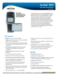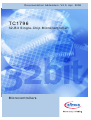
1
D o c um e n t a ti o n A d de n d u m , V 2 .0 , Ap r . 2 0 0 8
TC1796
3 2 - B i t S i n g l e - C h i p M i c ro c o n t r o ll e r
M i c r o c o n t r o l l e rs
Edition 2008-04
Published by Infineon Technologies AG,
81726 München, Germany
© Infineon Technologies AG 2008.
All Rights Reserved.
Legal Disclaimer
The information given in this document shall in no event be regarded as a guarantee of conditions or
characteristics (“Beschaffenheitsgarantie”). With respect to any examples or hints given herein, any typical values
stated herein and/or any information regarding the application of the device, Infineon Technologies hereby
disclaims any and all warranties and liabilities of any kind, including without limitation warranties of noninfringement of intellectual property rights of any third party.
Information
For further information on technology, delivery terms and conditions and prices please contact your nearest
Infineon Technologies Office (www.infineon.com).
Warnings
Due to technical requirements components may contain dangerous substances. For information on the types in
question please contact your nearest Infineon Technologies Office.
Infineon Technologies Components may only be used in life-support devices or systems with the express written
approval of Infineon Technologies, if a failure of such components can reasonably be expected to cause the failure
of that life-support device or system, or to affect the safety or effectiveness of that device or system. Life support
devices or systems are intended to be implanted in the human body, or to support and/or maintain and sustain
and/or protect human life. If they fail, it is reasonable to assume that the health of the user or other persons may
be endangered.
D o c um e n t a ti o n A d de n d u m , V 2 .0 , Ap r . 2 0 0 8
TC1796
3 2 - B i t S i n g l e - C h i p M i c ro c o n t r o ll e r
M i c r o c o n t r o l l e rs
TC1796
TC1796 Documentation Addendum
Revision History: V2.0 2008-04
Previous Versions: V1.0, V1.1, V1.2
Page
Subjects (major changes since last revision)
–
This is the first release that refers to the TC1796 User’s Manual V2.0, July
2007
Trademarks
TriCore® is a trademark of Infineon Technologies AG.
We Listen to Your Comments
Any information within this document that you feel is wrong, unclear or missing at all?
Your feedback will help us to continuously improve the quality of this document.
Please send your proposal (including a reference to this document) to:
[email protected]
Documentation Addendum
V2.0, 2008-04
TC1796
Table of Contents
Table of Contents
1
Introduction . . . . . . . . . . . . . . . . . . . . . . . . . . . . . . . . . . . . . . . . . . . . . . . . 3
2
User’s Manual - System Units Part (Volume 1) . . . . . . . . . . . . . . . . . . . .
Page 3-18 . . . . . . . . . . . . . . . . . . . . . . . . . . . . . . . . . . . . . . . . . . . . . .
Page 6-12 . . . . . . . . . . . . . . . . . . . . . . . . . . . . . . . . . . . . . . . . . . . . . .
Page 6-13 . . . . . . . . . . . . . . . . . . . . . . . . . . . . . . . . . . . . . . . . . . . . . .
Page 7-2 . . . . . . . . . . . . . . . . . . . . . . . . . . . . . . . . . . . . . . . . . . . . . . .
Page 7-34 . . . . . . . . . . . . . . . . . . . . . . . . . . . . . . . . . . . . . . . . . . . . . .
Page 7-35 . . . . . . . . . . . . . . . . . . . . . . . . . . . . . . . . . . . . . . . . . . . . . .
Page 7-36 . . . . . . . . . . . . . . . . . . . . . . . . . . . . . . . . . . . . . . . . . . . . . .
Page 10-83 . . . . . . . . . . . . . . . . . . . . . . . . . . . . . . . . . . . . . . . . . . . . .
Page 11-109, 11-111 . . . . . . . . . . . . . . . . . . . . . . . . . . . . . . . . . . . . . .
Page 12-34 . . . . . . . . . . . . . . . . . . . . . . . . . . . . . . . . . . . . . . . . . . . . .
4
4
4
4
4
4
5
5
8
9
9
3
User’s Manual - Peripheral Units Part (Volume 2) . . . . . . . . . . . . . . . .
Page 20-22 . . . . . . . . . . . . . . . . . . . . . . . . . . . . . . . . . . . . . . . . . . . .
Page 20-29 . . . . . . . . . . . . . . . . . . . . . . . . . . . . . . . . . . . . . . . . . . . .
Page 20-45 . . . . . . . . . . . . . . . . . . . . . . . . . . . . . . . . . . . . . . . . . . . .
Page 20-47 . . . . . . . . . . . . . . . . . . . . . . . . . . . . . . . . . . . . . . . . . . . .
Page 20-52 . . . . . . . . . . . . . . . . . . . . . . . . . . . . . . . . . . . . . . . . . . . .
Page 20-53 . . . . . . . . . . . . . . . . . . . . . . . . . . . . . . . . . . . . . . . . . . . .
Page 21-4 . . . . . . . . . . . . . . . . . . . . . . . . . . . . . . . . . . . . . . . . . . . . .
Page 21-13 . . . . . . . . . . . . . . . . . . . . . . . . . . . . . . . . . . . . . . . . . . . .
Page 21-18 . . . . . . . . . . . . . . . . . . . . . . . . . . . . . . . . . . . . . . . . . . . .
Page 21-19 . . . . . . . . . . . . . . . . . . . . . . . . . . . . . . . . . . . . . . . . . . . .
Page 21-25 . . . . . . . . . . . . . . . . . . . . . . . . . . . . . . . . . . . . . . . . . . . .
Page 21-26 . . . . . . . . . . . . . . . . . . . . . . . . . . . . . . . . . . . . . . . . . . . .
Page 21-34 . . . . . . . . . . . . . . . . . . . . . . . . . . . . . . . . . . . . . . . . . . . .
Page 21-47 . . . . . . . . . . . . . . . . . . . . . . . . . . . . . . . . . . . . . . . . . . . .
Page 21-57 . . . . . . . . . . . . . . . . . . . . . . . . . . . . . . . . . . . . . . . . . . . .
Page 21-66 . . . . . . . . . . . . . . . . . . . . . . . . . . . . . . . . . . . . . . . . . . . .
Page 21-68 . . . . . . . . . . . . . . . . . . . . . . . . . . . . . . . . . . . . . . . . . . . .
Page 21-69 . . . . . . . . . . . . . . . . . . . . . . . . . . . . . . . . . . . . . . . . . . . .
Page 22-43 . . . . . . . . . . . . . . . . . . . . . . . . . . . . . . . . . . . . . . . . . . . .
Page 22-54 . . . . . . . . . . . . . . . . . . . . . . . . . . . . . . . . . . . . . . . . . . . .
Page 22-59 . . . . . . . . . . . . . . . . . . . . . . . . . . . . . . . . . . . . . . . . . . . .
Page 22-70 . . . . . . . . . . . . . . . . . . . . . . . . . . . . . . . . . . . . . . . . . . . .
Page 22-72 . . . . . . . . . . . . . . . . . . . . . . . . . . . . . . . . . . . . . . . . . . . .
Page 22-204 . . . . . . . . . . . . . . . . . . . . . . . . . . . . . . . . . . . . . . . . . . .
Page 23-29, 23-34 . . . . . . . . . . . . . . . . . . . . . . . . . . . . . . . . . . . . . . .
Page 23-75 . . . . . . . . . . . . . . . . . . . . . . . . . . . . . . . . . . . . . . . . . . . .
Page 23-80 . . . . . . . . . . . . . . . . . . . . . . . . . . . . . . . . . . . . . . . . . . . .
10
10
10
10
10
10
10
10
10
11
11
11
11
11
11
12
12
12
12
13
13
13
13
13
13
13
13
13
Documentation Addendum
1
V2.0, 2008-04
TC1796
Table of Contents
Page 23-102 . . . . . . . . . . . . . . . . . . . . . . . . . . . . . . . . . . . . . . . . . . .
Page 23-103 . . . . . . . . . . . . . . . . . . . . . . . . . . . . . . . . . . . . . . . . . . .
Page 24-165 . . . . . . . . . . . . . . . . . . . . . . . . . . . . . . . . . . . . . . . . . . .
Page 24-248 . . . . . . . . . . . . . . . . . . . . . . . . . . . . . . . . . . . . . . . . . . .
Page 24-269 . . . . . . . . . . . . . . . . . . . . . . . . . . . . . . . . . . . . . . . . . . .
Page 25-107 . . . . . . . . . . . . . . . . . . . . . . . . . . . . . . . . . . . . . . . . . . .
Page 26-51 and 24-53 . . . . . . . . . . . . . . . . . . . . . . . . . . . . . . . . . . . .
Page 26-61 . . . . . . . . . . . . . . . . . . . . . . . . . . . . . . . . . . . . . . . . . . . .
Documentation Addendum
2
14
14
14
14
15
16
16
16
V2.0, 2008-04
TC1796
Introduction
1
Introduction
This document describes corrections, changes, and improvements for the two parts of
the TC1796 User’s Manual V2.0 2007-07, the System Units book (Volume 1) and the
Peripheral Units book (Volume 2). These corrections will be considered with the next
update of these User’s Manual documents.
The referenced documents to this addendum are located at the Internet page:
•
•
www.infineon.com/tc1796
TC1796 User's Manual System and Peripheral Units, V2.0 2007-07
Documentation Addendum
3
V2.0, 2008-04
TC1796
User’s Manual - System Units Part (Volume 1)
2
User’s Manual - System Units Part (Volume 1)
This section describes corrections for the System Units part of the User‘s Manual.
Page 3-18
Section 3.2.2.5 “Setting up the PLL after Reset” must be updated. Points 1. to 7. of this
section must be replaced by the following 9 points (red text indicates the changes):
1.
2.
3.
4.
5.
6.
7.
8.
9.
Wait until the oscillator is running (OSC_CON.OSCR = 1)
Selection of the VCO Bypass Mode (PLL_CLC.VCOBYP = 1)
Selecting the VCO band by programming PLL_CON.VCOSEL
Program the desired P, N and K values (PDIV, NDIV, and KDIV bit fields of register
PLL_CLC) to get a temporary fCPU value which is lower than the target
frequency.1)
Connect the oscillator to the PLL (PLL_CLC.OSCDISC = 0)
Wait until the PLL becomes locked (PLL_CLC.LOCK = 1)
Disable the VCO Bypass Mode (PLL_CLC.VCOBYP = 0)
Wait for typically 5ms until supply ripple caused by increased supply current
is faded away.
Decrease K value step by step, with wait phases in between, until the targeted
fCPU is reached.
Page 6-12
The first line in the description for bit field LEDAT[31:0] must be corrected into “LMB Data
Bits [31:0]” instead of “LMB Bus Address Bits [31:0]“.
Page 6-13
The first line in the description for bit field LEDAT[63:32] must be corrected into “LMB
Data Bits [63:32]” instead of “LMB Bus Address Bits [31:0]“.
Page 7-2
The item “Two PFLASH banks of 64 KByte each” at the bottom of the page must be
corrected into “Two DFLASH banks of 64 KByte each”:
Page 7-34
The note at the end of the page must be erased: “Note: After the detection …”.
1) K value selection should result in a small change of fCPU when bypass mode is left to reduce supply ripple.
Documentation Addendum
4
V2.0, 2008-04
TC1796
User’s Manual - System Units Part (Volume 1)
Page 7-35
The second sentence of the first paragraph must be erased: “With this features,
problematic …”
Paragraphs 3 to 6 must be erased: “Since problematic Flash array bits …” until “… of
Flash cells is close to the zero state”.
Page 7-36
The following section 7.2.8.3 (the text until middle of Page 8) must be added to the top
of page:
7.2.8.3 Application Hints Flash Error Handling
The previous sections described shortly the functionality of “error indicating” bits in the
flash status register FSR. This section gives recommendations how these should be
handled by customer software.
PFOPER/DFOPER “Operation Error”
Fault conditions:
ECC double-bit error detected in Flash microcode SRAM during a program or erase
operation in PFlash or DFlash. This can be a transient event due to alpha-particles or
illegal operating conditions or it is a permanent error due to a hardware defect. This
situation will practically not occur.
Attention: these bits can also be set during startup.
New state:
The Flash operation is aborted, the BUSY flag is cleared and read mode is entered.
Proposed handling by software:
The flag should be cleared with “Clear Status”. The last operation can be determined
from the PROG and ERASE flags1). In case of an erase operation the affected physical
sector must be assumed to be in an invalid state, in case of a program operation only the
affected page. Other physical sectors can still be read. New program or erase
commands must not be issued before the next reset.
Consequently a reset must be performed. This performs a new Flash ramp-up with
initialization of the microcode SRAM. The application must determine from the context
which operation failed and react accordingly. Mostly erasing the addressed sector and
re-programming its data is most appropriate. If a “Program Page” command was affected
and the sector can not be erased (e.g. in Flash EEPROM emulation) the wordline (two
consecutive pages, even followed by odd pages) could be invalidated if needed by
1) Only when both DFlash banks were busy, one with program and the other with erase the affected bank and
operation can not be determined.
Documentation Addendum
5
V2.0, 2008-04
TC1796
User’s Manual - System Units Part (Volume 1)
marking it with all-one data and the data could be programmed to another empty
wordline.
Only in case of a defective microcode SRAM the next program or erase operation will
incur again this error.
Note: Although this error indicates a failed operation it is possible to ignore it and rely on
a data verification step to determine if the Flash memory has correct data. Before
re-programming the Flash the flow must ensure that a new reset is applied.
Note: Even when the flag is ignored it is recommended to clear it. Otherwise all following
operations — including “sleep” — could trigger an interrupt even when they are
successful.
VER “Verification Error”
Fault conditions:
This flag is a warning indication and not an error. It is set when a program or erase
operation was completed but with a suboptimal result. This bit is already set when only
a single bit is left over-erased or weakly programmed which would be corrected by the
ECC anyhow.
However excessive VER occurrence can be caused by operating the Flash out of the
specified limits, e.g. incorrect voltage or temperature. A VER after programming can also
be caused by programming a page whose sector was not erased correctly (e.g. aborted
erase due to power failure).
Under correct operating conditions a VER after programming will practically not occur. A
VER after erasing is not unusual.
New state:
No state change. Just the bit is set.
Proposed handling by software:
This bit can be ignored. It should be cleared with “Clear Status” or “Reset to Read”. Inspec operation of the Flash memory must be ensured.
If the application allows (timing and data logistics), a more elaborate procedure can be
used to get rid of the VER situation:
•
•
VER after program: erase the sector and program the data again. This is only
recommended when there are more than 3 program VERs in the same sector. When
programming the DFlash in field (EEPROM emulation) ignoring program VER is
normally the best solution because its most likely cause are violated operating
conditions. Take care that never a sector is programmed in which the erase was
aborted. In the EEPROM emulation the algorithm must ensure this e.g. by
programming a marker after finishing successfully the erase.
VER after erase: the erase operation can be repeated until VER disappears.
Repeating the erase more than 3 times consecutively for the same sector is not
recommended. After that it is better to ignore the VER, program the data and check
Documentation Addendum
6
V2.0, 2008-04
TC1796
User’s Manual - System Units Part (Volume 1)
its readability. Again for EEPROM emulation its most likely cause are violated
operating conditions. Therefore it is recommended to repeat the erase at most once
or ignore it altogether.
For optimizing the quality of Flash programming see the following section about handling
single-bit ECC errors.
Note: Even when this flag is ignored it is recommended to clear it. Otherwise all following
operations — including “sleep” — could trigger an interrupt even when they are
successful.
PFSBER/DFSBER “Single-Bit Error”
Fault conditions:
When reading data or fetching code from PFlash or DFlash the ECC evaluation detected
a single-bit error (“SBE”) which was corrected.
This flag is a warning indication and not an error. A certain amount of single-bit errors
must be expected because of known physical effects.
New state:
No state change. Just the bit is set.
Proposed handling by software:
This flag can be used to analyze the state of the Flash memory. During normal operation
it should be ignored. In order to count single-bit errors it must be cleared by “Clear
Status” or “Reset to Read” after each occurrence.
Usually it is sufficient after programming data to compare the programmed data with its
reference values ignoring the SBE bits. When there is a comparison error the sector is
erased and programmed again.
When programming the PFlash (end-of-line programming or software updates)
customers can further reduce the probability of future read errors by performing the
following check after programming:
•
•
•
•
•
Change the read margin to “high margin 0”.
Verify the data and count the number of SBEs.
When the number of SBEs exceeds a certain limit (e.g. 10 in 2 MByte) the affected
sectors could be erased and programmed again.
Repeat the check for “high margin 1”.
Each sector should be reprogrammed at most once, afterwards SBEs can be
ignored.
In case of EEPROM emulation using DFlash the verification of programmed data should
be done with the normal read level and SBEs should be ignored. When a comparison
error is found the sector can usually not be erased because it contains active data in
other pages. The emulation algorithm can mark the affected page as invalid and program
the data to a following page. As always the number of consecutive repetitions should be
limited (e.g. to 3) as protection against violated operating conditions.
Documentation Addendum
7
V2.0, 2008-04
TC1796
User’s Manual - System Units Part (Volume 1)
To keep the EEPROM emulation alive even when wordline (two consecutive pages,
even followed by odd pages) oriented fails occur (e.g. due to over-cycling) the algorithm
can implement the following scheme for highest possible robustness:
•
•
•
•
Before programming a page save the content of the other page on the same wordline
in SRAM.
Program the new page and compare the content with the reference data. This can be
done with normal read margins. Ignore SBEs.
If the data comparison fails program this page and the saved content of the other
page to a different wordline.
This procedure can be repeated if the data comparison fails again. The number of
repetitions should be limited (e.g. to 3) in case the programming fails because of outof-spec operating conditions.
Due to the specificity of each application the appropriate usage and implementation of
these measures (together with the more elaborate VER handling) must be chosen
according to the context of the application.
Page 10-83
On this page the expression ”SLSOx” must be replaced by “SLSOn”.
Documentation Addendum
8
V2.0, 2008-04
TC1796
User’s Manual - System Units Part (Volume 1)
Page 11-109, 11-111
In Table 10-15, the number of clock cycles for the stated instructions must be corrected
as below:
Table 11-15 Instruction Timing
Instruction
Number of Clock Cycles
Comments
Notes
MCLR.PI
6
–
–
MSET.PI
6
–
–
ST.PI
4
–
–
XCH.PI
5
–
–
11
–
–
PRAM Access
Complex Maths
MSETP.U
At Page 11-111, the last row of footnote 7 must be changed to “32 x 32 bit multiply
requires instruction MINIT + 4 x MSTEP.U = 1 + 4 x 11 = 45 cycles”.
Page 12-34
The first bulleted point must be changed to “The activation of the interrupt corresponding
to the current active channel 0n using the Interrupt Pointer defined in CHICRmn.INTP.”.
Documentation Addendum
9
V2.0, 2008-04
TC1796
User’s Manual - Peripheral Units Part (Volume 2)
3
User’s Manual - Peripheral Units Part (Volume 2)
This section describes corrections for the Peripheral Units part of the User‘s Manual.
Page 20-22
The expression ”SLSOx” must be replaced three times by “SLSOn”.
In the numbered paragraph “3.” the expression “SSSOTC.INACT“ must be changed into
“SSOTC.INACT”.
Page 20-29
The description for the Module Revision Number bit field for the ID register must be
changed to ”MODREV defines the module revision number. The value of a module
revision starts with 30H for SSC0 and 10H for SSC1 (first revisions).”
Page 20-45
The bit description for bit TB_VALUE must begin with “Register TB stores the data
value ....”.
Page 20-47
On the top of this page the expression ”SLSOx” must be replaced two times by “SLSOn”.
Page 20-52
The content “rw” of column “Type” in the last row of the table on top of the page for the
“Reserved” bits must be changed into “r“.
Page 20-53
In the text on top of this page and in Figure 20-19 the expression ”SLSOx” must be
replaced by “SLSOn” (in total four times on this page). Index “x” in Figure 20-19 must be
replaced by “n”. Additionally, “index “x”” must be replaced by “Index “n””.
Page 21-4
The item “- Programmable upstream data frame length (16 or 12 bits)” must be moved
from the second bullet as third item under the third bullet “Low-speed asynchronous
serial reception on upstream channel”.
Page 21-13
in the last bullet line on the bottom of the page “DDL” must be changed into “DCL“.
Documentation Addendum
10
V2.0, 2008-04
TC1796
User’s Manual - Peripheral Units Part (Volume 2)
Page 21-18
On the top of the page “DSS.DC” must be changed into “DSS.PFC“.
Page 21-19
In the paragraph above Figure 21-12 “(ENSELL=0)” must be changed into
“(ENSELH=0)“.
Page 21-25
In Table 21-6 column USR.URR fourth line “010B” must be changed into “011B”.
Page 21-26
In the first paragraph on the top of the page “OCSR.URR” must be changed into
“USR.URR”.
Page 21-34
In the paragraph above Figure 21-26 “ISC.SRDI and ISC.CRDI” must be changed into
“ISC.SURDI and ISC.CURDI”.
Figure 21-26 must be updated with the following figure (output signal on the right side):
ISC
ICR
RDIE
2
Software ISR
Clear
CURDI
URDI
SURDI
Set
RDIE = 00
Data is received
01
Data is received and
not equal 00 H
10
Data is received in UD 3
11
Software
Set
≥1
Hardware
Set
RDI
Receive Data
Interrupt
(to Int. Comp .)
MCA05820a_mod
Figure 21-26 Receive Data Interrupt Control
Page 21-47
The paragraph on the top of the page must be changed into:
“The bit fields of the Downstream Select Data Source High Register DSDSH determine
the data source for each bit in shift register SRH.“
The register description table must be changed as follows:
Documentation Addendum
11
V2.0, 2008-04
TC1796
User’s Manual - Peripheral Units Part (Volume 2)
SHx
(x = 0-15)
[2*x+1: rw
2*x]
Select Source for SRH
SHx determines which data source is used for the shift
register bit SRH[x] during data frame transmission.
00B SRH[x] is taken from data register DD.DDH[x].
01B Reserved.
10B SRH[x] is taken from the ALTINH input line x.
11B SRH[x] is taken from the ALTINH input line x in
inverted state.
Page 21-57
n the bit description of bit CSH “SRL” must be changed into “SRH”.
Page 21-66
Five of the six formulas on this page must be changed as follows (“MSCx_FDR.STEP”):
1
n
f MSCx = f SYS × --- with n = 1024 - MSCx_FDR.STEP
(21.3)
1
Baud rate MSCx = f SYS × ---------------------------------------------------------------------------------2 × ( 1024 - MSCx_FDR.STEP )
(21.5)
MSCx_FDR.STEP
Baud rate MSCx = f SYS × ------------------------------------------------2 × 1024
(21.6)
1
Baud rate MSCx = f SYS × --------------------------------------------------------------------------------------DF × ( 1024 - MSCx_FDR.STEP )
(21.7)
MSCx_FDR.STEP
Baud rate MSCx = f SYS × ------------------------------------------------DF × 1024
(21.8)
Page 21-68
In the bit description for bit SUSACK in the register description table “Indicates state of
SPNDACK signal.“ must be changed into “Indicates state of SPNDACK signal.
Page 21-69
The content “rw” of column “Type” in the last row of the table on top of the page for the
“Reserved” bits must be changed into “r“.
Documentation Addendum
12
V2.0, 2008-04
TC1796
User’s Manual - Peripheral Units Part (Volume 2)
Page 22-43
In the two bulleted points in section “Allocation Case 1” the register name “MOINPRn”
must be replaced twice into “MOIPRn”.
Page 22-54
The second sentence in the last but one paragraph must be changed to “Transmit
acceptance filtering evaluates TXEN1 for each message object and a message object
can win transmit acceptance filtering only if its TXEN1 bit is set.”
Page 22-59
The offset addresses of all message object registers in Table 22-5 must be “600H + ....”
instead of “400H + ....”
Page 22-70
The first sentence of the page must be changed to “When a message object n generates
an interrupt request upon the transmission or reception of a message, then the request
is routed to the interrupt output line selected by the bit field MOIPRn.TXINP or
MOIPRn.RXINP of the message object n.”.
Page 22-72
In the bit field description of Message Index Mask “MSPNDn“ must be replaced by
“MSPNDk“.
Page 22-204
The content “rw” of column “Type” in the last row of the table on top of the page for the
“Reserved” bits must be changed into “r“.
Page 23-29, 23-34
At both pages, the first bullet paragraphs from the top of the pages should be extended
at its end by the following text: “... are not taken into account, assuming the buffer size
is configured correctly (see Page 23-102).”
Page 23-75
In Figure 23-50, the TCDMR text within the Transmission Status/Control Registers block
must be corrected to “TCMDR”.
Page 23-80
The content “rw” of column “Type” in the last row of the table on top of the page for the
“Reserved” bits must be changed into “r“.
Documentation Addendum
13
V2.0, 2008-04
TC1796
User’s Manual - Peripheral Units Part (Volume 2)
Page 23-102
The description of bit field BS should be extended in the following way:
1. Adding the bit field combination “1101B 14-bit offset address of Remote Window”
2. Adding the following text after bit combination 1111B: “Do not use the values 1101B,
1110B, and 1111B as buffer size BS for Small Transfer Windows.“
Page 23-103
The bit description of AOFF should be extended at its end by the following text: “... are
not taken into account for further actions, assuming the buffer size is configured
correctly (see Page 23-102).”
Page 24-165
The bit description of bit PLLCTR.AEN must be changed as follows:
AEN
2
rw
Automatic End Mode Enable
With the Automatic End Mode the compensation of
input signal’s period length variation (acceleration,
deceleration) is requested.
0B
Automatic End Mode is disabled.
1B
Automatic End Mode is enabled.
Page 24-248
Figure 24-86 must be updated with the following figure (LTCPRE input of LTCA2):
Documentation Addendum
14
V2.0, 2008-04
TC1796
User’s Manual - Peripheral Units Part (Volume 2)
fC L C
IN[55:0]
56
OUT[55:0]
56
8
P2.8
P2.15
16
P3.0
P3.15
16
P4.0
P4.15
8
P8.0
P8.7
8
P9.0
P9.7
fGPTA 0
Clock
Control
GT0xRUN
2
Port
Control
GT1xRUN
fGPTA 1
fL TC A2
GPTA0
56
OUT[111 :56]
SR
[37:00]
40
INT[3:0]
2
2
2
IO
Groups
IOG[6:0]
OUT5
PLL Clocks
INT0
SR15 MultiCAN
INT[3:0]
8
IN[55:0]
Interrupt
Control
SR
[37:00]
GPTA1
OUT[55:0]
16
56
OUT
[111:56]
LTCPRE
SR
[15:00]
56
56
8 CLK[7:0]
MSC
Mux
Control
16
Output
Groups
OG[6:0]
16
LTCA2
8
MSC0
MSC1
INT[3:0]
IN[39:0]
Address
Decoder
FADC
9
OUT[39:0]
OUT
[111:56]
INT[3:1]
3
SCU
(Ext.
Request
Unit )
ADC0
ADC1
DMA
MCB05995_mod
Figure 24-86 Block Diagram of GPTA Implementation
Page 24-269
The content “rw” of column “Type” in the last row of the table on top of the page for the
“Reserved” bits must be changed into “r“.
Documentation Addendum
15
V2.0, 2008-04
TC1796
User’s Manual - Peripheral Units Part (Volume 2)
Page 25-107
The content “rw” of column “Type” in the last row of the table on top of the page for the
“Reserved” bits must be changed into “r“.
Page 26-51 and 24-53
The bit field descriptions of CRR0.AC and CRR1.AC must be changed as follows:
AC
[26:24] rh
Addition Count
With the Automatic End Mode the compensation of
input signal’s period length variation (acceleration,
deceleration) is requested.xxThis bit field indicates
the number of additions of filter input values with
remain to be executed before the next intermediate
result register transfer occurs. AC is loaded with the
value of FCRn.ADDL for a new addition sequence,
also when writing GCR.RSTFn = 1.
Page 26-61
The content “rw” of column “Type” in the last row of the table on top of the page for the
“Reserved” bits must be changed into “r“.
Documentation Addendum
16
V2.0, 2008-04
w w w . i n f i n e o n . c o m
Published by Infineon Technologies AG