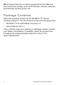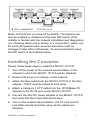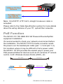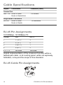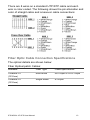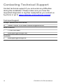
1
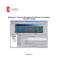
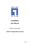
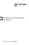
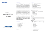
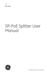
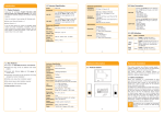
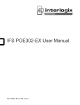
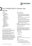
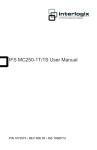
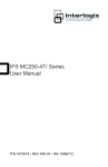
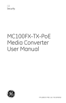
IFS MC201-1P/1FS
User Manual
P/N 1076525 • REV A • ISS 07FEB12
Copyright
Trademarks and
patents
Manufacturer
Version
Certification
FCC compliance
ACMA
compliance
European Union
directives
© 2012 UTC Fire & Security Company. All rights
reserved.
Interlogix, IFS MC201-1P/1FS, the IFS Brand and
logo are trademarks of UTC Fire & Security.
Other trade names used in this document may be
trademarks or registered trademarks of the
manufacturers or vendors of the respective
products.
UTC Fire & Security Americas Corporation, Inc.
2955 Red Hill Avenue, Costa Mesa, CA
92626-5923, USA
This document applies to IFS MC201-1P/1FS
version 1.0.
N4131
Class A: This equipment has been tested and
found to comply with the limits for a Class A digital
device, pursuant to part 15 of the FCC Rules.
These limits are designed to provide reasonable
protection against harmful interference when the
equipment is operated in a commercial
environment. This equipment generates, uses,
and can radiate radio frequency energy and, if not
installed and used in accordance with the
instruction manual, may cause harmful
interference to radio communications. Operation
of this equipment in a residential area is likely to
cause harmful interference in which case the user
will be required to correct the interference at his
own expense.
Notice! This is a Class A product. In a domestic
environment this product may cause radio
interference in which case the user may be
required to take adequate measures.
2004/108/EC (EMC directive): Hereby, UTC Fire
& Security declares that this device is in
compliance with the essential requirements and
other relevant provisions of Directive 2004/108/EC
2002/96/EC (WEEE directive): Products marked
with this symbol cannot be disposed of as
unsorted municipal waste in the European Union.
For proper recycling, return this product to your
local supplier upon the purchase of equivalent
new equipment, or dispose of it at designated
collection points. For more information see:
www.recyclethis.info.
Contact
information
Customer support
www.utcfireandsecurity.com or
www.interlogix.com
www.interlogix.com/customer-support
Contents
Overview 1
About the MC201-1P/1FS 1
Package Contents 2
Hardware Overview 3
Front Panel 4
Back Panel 4
Link Fault Pass-through (LFP) 4
Link Loss Carry Forward (LLCF) 5
Link Loss Return (LLR) 6
Installing the Converter 7
PoE Function 8
LED Indicators 9
System 9
10/100Base-TX Port 9
100Base-FX SC Port 9
Specifications 11
Cable Specifications 12
RJ-45 Pin Assignments 12
RJ-45 Cable Pin Assignments 12
Fiber Optic Cable Connection
Specifications 13
Contacting Technical Support 14
IFS MC201-1P/1FS User Manual
i
Overview
Thank you for purchasing the IFS MC201-1P/1FS 10/100Mbps
Ethernet Twisted pair to 100Base-FX fiber optic PoE Bridge
Converter. This converter is used to convert one type of media
signal to a different type of media that allows two segments to
connect easily, efficiently and inexpensively. The converter
supports Power over Ethernet to power one IEEE 802.3af
compliant powered device.
About the MC201-1P/1FS
The MC201-1P/1FS is an IEEE 802.3af Power over Ethernet
Converter that supplies 48 VDC over Ethernet cable. The
MC201-1P/1FS IEEE 802.3af Power over Ethernet Converter
inserts DC Voltage onto a Category 5 cable, allowing the cable
between the Converter (MC201-1P/1FS) and PoE PD
(Powered Device) to transfer data and power simultaneously.
The maximum distance between the Converter (MC2011P/1FS) and PoE PD is 328 ft. (100m). MC201-1P/1FS
combines Ethernet with IEEE 802.3af power and transfers
over the twisted pair cables. A PoE splitter can be used to
separate the Ethernet data and power if needed to power a
non-PoE device.
With the MC201-1P/1FS, only one Ethernet cable is needed to
carry both power and data to each device providing simpler
network designs, higher reliability while reducing costs.
Note: PSE (Power Sourcing Equipment) is a device (switch, or
hub for instance) that will provide power in a PoE setup. The
maximum allowed continuous output power per such device is
15.4W according to the IEEE 802.3af standard.
IFS MC201-1P/1FS User Manual
1
PD (Powered Device) is a device powered by the PSE and
thus consumes energy, such as IP Phones, network cameras
and Wireless access points, etc.
Package Contents
Open the package containing the MCR205-1T/1S and
carefully unpack it. The box should contain the following items:
•
MCR205-1T/1S PoE Media Converter x1
•
User’s Manual CD x1
If any of these items are missing or damaged, please contact
your dealer immediately. If possible, retain the product box
including the original packing material to return it for
repair/replacement.
2
IFS MC201-1P/1FS User Manual
Hardware Overview
Figure 1: Physical Layout
IFS MC201-1P/1FS User Manual
3
Front Panel
There is one RJ-45 Twisted-Pair jack (Auto-MDI/MDI-X), one
fiber-optic connector and four LED indicators on the MC2011P/1S front panel.
Back Panel
There is one DIP switch for turning the Link Fault Passthrough feature on or off, and 48V DC power input located at
the back panel. The back panel also has one 48 VDC power
socket for the MC201-1P/1S.
Note: Please make sure that the 48VDC power supply used is
capable to provide 0.32A to support full PoE load.
Link Fault Pass-through (LFP)
The LFP function refers to the Link Fault Pass-through
function (LLCF/LLR) and the DIP Switch design. LLCF/LLR
can immediately notify administrators about a connectivity
problem. The DIP Switch enables or disables the LFP function.
4
IFS MC201-1P/1FS User Manual
LLCF (Link Loss Carry Forward) detects the connection loss
on the TP line, and LLR (Link Loss Return) detects the
connection loss on the fiber line.
Link Loss Carry Forward (LLCF)
The MC201-1P/1FS incorporates an LLCF function for
troubleshooting a remote connection. When LFP function is
enabled, the FL/TP ports do not transmit a link signal until they
receive a link signal from the opposite port.
The diagram below shows a typical network configuration with
a good link status using MC201-1P/1FS for remote
connectivity.
In case of a connectivity issue, the MC201-1T/1FS media
converter LLCF sends the notification to the switch/hub that
generates a trap to the management station.
* The default is set to OFF for LFP function.
IFS MC201-1P/1FS User Manual
5
Link Loss Return (LLR)
The fiber ports of the MC201-1P/1FS have been designed with
an LLR function for troubleshooting a connectivity issue. LLR
works in conjunction with LLCF.
When LFP function is enabled, the port’s transmitter shuts
down when its receiver fails to detect a valid connection. LLR
should only be enabled on one end of the link and is typically
enabled on either the unmanaged or remote device.
The diagram below shows a typical network configuration with
a good link status using MC201-1P/1FS for remote
connectivity. Note that LLR and LLCF are enabled as indicated
in the diagram.
If one of the optical conductors is bad (as shown in the
diagram box below), the fiber converter with LLR function will
return a no-link condition to its link partner. With LLCF function
also enabled, the no-link condition is carried forward to the
switch/hub where a trap is generated to the management
station.
6
IFS MC201-1P/1FS User Manual
Note: LFP function is turned-off by default. This feature can
also be enabled or disabled via the side DIP-switch. If the
installer is familiar with the network installation and diagnostics
(i.e. checking which end is broken in a connection), switch can
be set to ON position and converter should be reset for
changes to take effect. Otherwise, it's recommended to keep
the DIP switch in its default position.
Installing the Converter
Please follow these steps to install the MC201-1P/1FS:
1. Turn off the power of the network device/station in the
network to which the MC201-1P/1FS will be attached.
2. Ensure that there is no activity on the network.
3. Attach the fiber cable from the MC201-1P/1FS to the fiber
network. TX/RX must be paired at both ends.
4. Attach a Category 5 UTP cable from the 10/100Base-TX
network to the RJ-45 port on the MC201-1P/1FS.
5. Connect the 48V DC power adapter to the MC201-1P/1FS
and verify that the Power LED illuminates.
6. Turn on the network device/station, the TX Link and FX
Link LEDs should illuminate when all the cables are
attached.
IFS MC201-1P/1FS User Manual
7
TX
RX
RX
TX
100Base-FX Fiber
Network
10/100Base-TX
Cat. 5/5e TP
Cable Network
Note: RJ-45/STP, UTP Cat 5, straight /crossover cable is
accepted.
Please refer to the Cable Specification section for more details
about the wiring distance of your TP, optical fiber networks.
PoE Function
The MC201-1P/1FS IEEE 802.3af Powered Device/Splitter
equipment installation:
It's recommended to check your network environment before
the installation. The MC201-1P/1FS media converter sends
the power over the twisted pair cable (pair 1, 2 and pair 3, 6).
For locations where it may be difficult to find a power outlet,
the MC201-1P/1FS provides the easiest way to power your
PoE powered Ethernet devices such as IP cameras, IP access
control, VoIP, Wireless Access Points (WAP), etc.
2km~15km
100 meters
Data
Data+Power
PoE
Wireless AP
Fiber Switch
Power
8
IFS MC201-1P/1FS User Manual
Note: The PoE feature requires the use of a recommended
power adapter.
LED Indicators
System
LED
Color
PWR
Green
Function
Lit
Indicates the device is powered.
10/100Base-TX Port
LED
Color
Function
Blink Indicates that the Media Converter is
actively sending or receiving data over that
port.
LNK/ACT
PoE in Use
Lit
Indicates that the connection through the
port is successfully established.
Off
Indicates that the connection through the
port is not established.
Lit
Indicates that the port is providing PoE to
the connected device.
Off
Indicates that the port is not providing PoE
to the connected device.
Green
Green
100Base-FX SC Port
LED
Color
Function
Blink
LNK/ACT
Green
Indicates that the Media Converter is actively
sending or receiving data over the port.
Lit
Indicates that the port link is up.
Off
Indicates that the port link is down.
Note: Fiber optic port should be set to the correct mode
according to this LNK/ACT indicator for optimal network
performance.
IFS MC201-1P/1FS User Manual
9
10
IFS MC201-1P/1FS User Manual
Specifications
Ethernet
Data Rate
Throughput (packet per second)
Switch Architecture
10/100/1000Mbps
148810pps@64Bytes
Store-and-Forward
Back pressure for Half-Duplex mode
Flow Control
Pause from for Full-Duplex mode (IEEE 802.3x)
Connector
RJ-45 with Auto-MDI/MDI-X and PoE injector function
Cable Type and Distance
10Base-T (Cat 3, 4, 5e) or 100Base-T (Cat 5e) – 328ft (100m)
Fiber
MC100FX-TX-PoE
MC201-1P/1FS
Data Rate
100Base-FX
100 Base-FX
Connector
SC
SC
Fiber Type
Multi-mode (50/125μm or 62.5/125μm
Single mode (9/125μm)
Distance
Up to 2km
Up to 15km
Power Over Ethernet (PoE)
PoE Standard
IEEE 802.3af
Power Pin Assignment
(+) Pins 1 & 2; (–) Pins 3 & 6
Power Output (Max. 1 PoE Device)
PoE 48 VDC, Max. 15.4 watts, 350mA
LED Indicators
Power Status
On - Green
10/100Base-T Link
Data Activity - Green
100Base-FX Link
Data Activity - Green
PoE In Use
Detection of PSE Device - Green
LFP Mode Switch
On
If either TX or FX port is faulty, disable other port
Off
Active link LED will still operate if other port is faulty
Electrical and Mechanical
Input Power
48VDC @ 0.38A
Enclosure
Metal
Dimensions (H x W x D)
1.02 x 2.76 x 3.82 in. (26 x 70 x 97 mm)
Weight
0.44 lbs. / 200g
Environmental
Operating Temperature
0ºC~50ºC
Storage Temperature
-120ºC~70ºC
Relative Humidity
0%–90% (non-condensing)
IFS MC201-1P/1FS User Manual
11
Cable Specifications
Duplex
Connection
Limitation (max.)
Twisted Pair
Half / Full Node to Node
Node to Switch/Hub
100 meters
Single-Mode Converters
SM Full
Node to Node
Node to Switch
15 kilometers
RJ-45 Pin Assignments
10/100Mbps, 10/100Base-TX
Contact
MDI
MDI-X
1
1 (TX +)
3
2
2 (TX -)
6
3
3 (RX +)
1
6
6 (RX -)
2
4, 5, 7, 8
Not used
Not used
Implicit implementation of the crossover function within a
twisted-pair cable, or at a wiring panel, while not expressly
forbidden, is beyond the scope of this standard.
RJ-45 Cable Pin Assignments
12
IFS MC201-1P/1FS User Manual
There are 8 wires on a standard UTP/STP cable and each
wire is color-coded. The following shows the pin allocation and
color of straight cable and crossover cable connections:
Fiber Optic Cable Connection Specifications
The optical details are shown below:
Fiber Optical patch Cables:
Standard
Fiber Type
Cable Specification
100Base-FX
(1310nm)
Multi-mode
50/125μm or 62.5/125μm
100Base-FX
(1310nm)
Single-mode
9/125μm
IFS MC201-1P/1FS User Manual
13
Contacting Technical Support
Contact technical support if you encounter any difficulties
during this installation. Please make sure you have the
requested diagnostic or log files ready before you contact us
by phone or go to www.interlogix.com/customer-support.
Technical Support
Europe, Middle East and Africa
W
Select Contact Us at www.utcfssecurityproducts.eu
North America
T
+1 855.286.8889
E
[email protected]
Australia
E
14
[email protected]
IFS MC201-1P/1FS User Manual