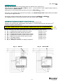
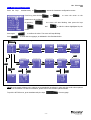
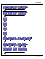
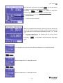
1
Man. PS0109 USER MANUAL Man. PS0109 Congratulations for choosing Polar Star, a product stemming from Elcontrol 50-year experience in the control of energy consumption. The high technology content, the careful attention to the choice of materials, the full compliance to the most recent industrial standards make this tool the 'Polar Star' for effectively and simply finding your way to energy analysis. Further, Polar Star has been fully developed and tested in Italy. It is therefore manufactured with those high quality standards for all European products, in compliance with the environment, safety and ethics. -2- Man. PS0109 TABLE OF CONTENTS Page 1 2 3 4 5 Presentation Safety 2.1 Operator Safety 2.2 RoHS & WEEE EC Declaration of Conformity 2.3 Reference Standards 2.4 Warranty Conditions Installation 3.1 Power Supply and Electrical Connections 3.1.1 Power Supply 3.1.2 Connection of Voltage and Amperometric Inputs Start-up 4.1 User Interface 4.1.1 Set-up and Measurement Pages 4.1.2 Keypad 4.2 Programming and Set-up 4.2.1 Connections Set-up 4.2.1.1 Electrical Connection Set-up 4.2.1.2 Voltage Ratio Set-up (VT) 4.2.1.3 Current Ratio Set-up (CT) 4.2.1.4 Current Ratio Set-up of I Neutral 4.2.1.5 Cogeneration Set-up 4.2.1.6 Neutral Current Set-up 4.2.2 Minimum, Maximum and Average Set-up 4.2.2.1 Integration Time Set-up 4.2.2.2 Average Values and Maximum Demand Reset 4.2.2.3 Minimum and Maximum Reset 4.2.3 Counters Reset 4.2.4 Language Set-up 4.2.5 LCD Set-up 4.2.5.1 Backlight Set-up 4.2.5.2 Contrast and Brightness Set-up 4.2.5.3 Menu Set-up 4.2.6 Clock Set-up 4.2.7 Bottom Bar Set-up 4.2.8 Tariff Band Set-up 4.2.8.1 Tariff Configuration and Reset 4.2.9 Trend Set-up and Reset 4.2.10 50160 Set-up and Reset 4.2.11 Alarm Set-up and Reset 4.2.11.1 Alarm Configuration 4.2.12 Set-up Protection Password Instrument Use and Consultation 5.1 Connections Check 5.2 Measurement Menu Scrolling 5.3 Three-phase or Two-phase Connection Menu 5.3.1 Voltage Menu 5.3.2 Current Menu 5.3.3 Power Menu 5.3.4 Counters Menu 5.3.5 THD Menu 5.3.6 Harmonics Menu 5.3.7 Waveform Menu 5.3.8 Tariff Band Menu 5.3.9 Trend Menu 5.3.10 EN50160 Menu 5.3.11 Alarm Log Menu -3- 5 6 6 6 7 8 9 9 10 10 13 13 13 14 15 16 16 16 16 16 16 16 17 17 17 17 17 17 18 18 18 18 18 19 19 19 20 20 20 21 21 22 22 22 27 27 28 29 30 31 31 33 34 35 36 37 Man. PS0109 5.4 6 7 8 9 Single-phase Connection Menu 5.4.1 V I PF F Menu 5.4.2 P Q S PF Menu 5.4.3 Counters Menu 5.4.4 THD Menu 5.4.5 Harmonics Menu 5.4.6 Waveform Menu 5.4.7 Tariff Band Menu 5.4.8 Trend Menu 5.4.9 EN50160 Menu 5.4.10 Alarm Log Menu Maintenance 6.1 Accuracy Checking 6.2 Repair 6.3 Trouble Tracing Software Polarlink Technical Specifications Option Modules 9.1 RS485 Option Modules 9.1.1 RS485 Option Connections 9.1.2 RS485 Option Set-up 9.1.3 Communication Test 9.1.4 Date/Time Synchronization 9.1.5 MODBUS Measurement Registers 9.2 ALM Option 9.2.1 ALM Option Connections 9.2.2 ALM Option Set-up 9.2.3 Alarm 1 or 2 Set-up 9.2.4 Pulse 1 or 2 Output Set-up 9.3 Digital Inputs Option 9.3.1 Digital Inputs Option Connections 9.3.2 Digital Inputs Set-up 38 38 39 40 40 40 40 41 41 41 41 42 42 42 42 43 44 46 46 46 46 47 47 47 56 56 56 56 57 57 57 58 -4- Man. PS0109 1 - PRESENTATION Polar Star is a state-of-the-art device equipped with new functions for monitoring energy consumption and for advanced energy and quality analysis. This device is able to measure, display, process and transmit all the parameters of a plant. With respect to standard energy analysers, its main features are as follows: new standard format enclosure (DIN 96x96 mm) which really conforms to IEC 61554, with a modern and sophisticated design: ● reduced depth and only 4 cm overall dimensions inside the control board; ● Front panel IP65 protection rating (total resistance to dust and water jets coming from all directions); ● Plug & Play optional devices can be easily inserted at the back of the device (RS485 power supply digital input and output alarms, 12-24 Vdc and 48-60Vdc, Wireless transmission, etc.); for use with power supply and current and voltage inputs of flanged connectors (completely removable but with retaining screws) providing quick installation and total electrical safety thanks to the perfect tightening between male and female connectors; switching power supply, 90 ÷ 230V∼ 50-60Hz and 90 ÷ 300V (+ options 12÷24V and 48÷60V ) backlit graphic LCD, high efficiency 128x128 pixels for a high quality display (multilingual menu, waveforms, histograms, customised pages, charts, schemes, images, etc.); 3 voltage measuring channels up to 600V Cat III, with a ±0.25%+0.05FS accuracy 4 independent current inputs (3 + 1 which may be used for measuring, for example, the neutral current), with a ±0.25%+0.05FS accuracy 4 internal CTs for improved electrical insulation* new calculation engine based on a new 16-bit microprocessor which provides measuring of all standard measures (V I P Q A F PF THD% etc.) with effective value (TRMS) and: ● measuring of minimum, average maximum and instant values on 4 dials (absorbed and generated type) ● password-protectable energy counters (kWh kVA kVAr) for both absorbed and produced energy; ● Energy quality analysis through measuring of: current and voltage harmonics (all 7 input channels) up to the 31st order; power and micro-power blackouts* Dips (voltage losses)* Swells (overvoltages)* EN50160 test (reference standard for energy quality)* ● Event data logger (5 alarms, 5 dips, 5 swells, 5 interruption)* ● graphic display of trends (time progress) of 5 selectable measures* ● energy measurement in 4 time periods (tariffs)* (tariffs can be freely set) ● For both three-phase and each single phase!!! ● 6 electrical systems which can be analysed: (i) single-phase type; (ii) two-phase type; (iii) three-phase with 3 leads (unbalanced type); (iv) three-phase with 4 leads (unbalanced type); (v) three-phase with 3 leads (balanced type); (vi) three-phase with 4 leads (balanced type); ● mean voltage connection is possible Users can customise the screens according to their preferences; Multilingual menu (English, Italian, German, Spanish and French); Automatic test connection for checking the electrical connections; Automatic option recognition; Check of RS485 communication (if any); Dedicated PC software for detecting and remotely configuring the instrument* * only for TOP model -5- Man. PS0109 2 - SAFETY Polar Star has been designed and tested in compliance with the most recent industrial Directives and is supplied by the manufacturer in perfect technical safety conditions. In order to maintain these conditions and ensure safe operation, the user should follow the instructions and the markings in these user instructions. Read these pages carefully before installing and using this device! 2.1 - Operator Safety ● ● ● ● ● ● ● The instrument described in this manual is intended to be used only by properly trained personnel. Maintenance and installation operations should be carried out only by qualified and authorised personnel in order to avoid any risk of electrocution, shock or burns. For proper and safe use of the device and for its installation and maintenance, the people in charge of these operations should observe standard safety procedures. Failure to do so will relieve the manufacturer of all responsibilities. Before using, servicing or repairing, disconnect the instrument and the housing board from any voltage source. Before performing the electrical connections or any interventions on the device, short-circuit the CT secondary winding and switch off the power supply. Before the start-up, check the following: ! network voltage should fall within the range indicated in the specification; ! the maximum voltage at the voltage inputs should be 700VAC phase/phase or 400VAC phase/neutral After checking that safe operation is no longer possible, the instrument should be taken out of service and ensured against accidental use. Safe operation is no longer possible in the following cases: ! when the instrument exhibits clearly visible damages; ! when the instrument is not working anymore; ! after long storage under negative conditions; ! after serious damages undergone during transport. When you find this symbol on the product or anywhere else, you have to consult the instruction manual. 2.2 - RoHS & WEEE EC Declaration of Conformity Manufacturer: ELCONTROL ENERGY NET S.r.l. Via Vizzano 44 - 40044 Sasso Marconi (BO) - Italy Product: POLAR STAR Energy Analyser Compliance with Directives: 93/68/EEC (LV electrical equipment); 89/336/EEC and 2004/108/EC (EMC - Electromagnetic Compatibility) 2006/95/EC - 72/23/EEC (LVD - Low Voltage Directive); 2002/95/EC (RoHS - Restriction of Hazardous Substances); 2002/96/EC and 2003/108/EC (WEEE: Waste Electrical and Electronic Equipment) Mark affixing date: 2009 Reference standards taken into account for EC compliance: IEC IEC IEC IEC IEC Reference standard for mechanical dimensions: IEC 61554 (ex DIN 43700) -6- EN EN EN EN EN 61010-1 61326 61326/A1 61326/A2 61326/A3 Man. PS0109 2.3 - Reference Standards IEC standard Title EN 61010-1 Safety requirements electrical equipment measurement, control laboratory use. EN 61326 Electrical equipment measurement, control laboratory use. EMC requirements. IEC EN 61326/A1 Electrical equipment measurement, control laboratory use. EMC requirements. IEC EN 61326/A2 Electrical equipment measurement, control laboratory use. EMC requirements. IEC EN 61326/A3 Electrical equipment measurement, control laboratory use. EMC requirements Description Internat. Connect. General safety requirements for electrical for Identical to equipment for professional, industrial and for educational use: and IEC 61010-1:2001-02 test and measuring electrical equipment EN 61010-1:2001-03 for setting and laboratory. The present standard indicates the minimum requirements for immunity and issue as regards the electromagnetic compatibility of electrical equipment with power supply lower than 1,000 V AC or Identical to for 1,500 V DC for professional and and educational use or for industrial processes IEC 61326-1: 1997-03 including electronic processing devices EN 61326-1:1997-04 and equipment: measuring and test EN 61326-1 Ec:1998-01 summation; control summation, summation for laboratory use, summation for accessories which are not intended to be used with the above-mentioned equipment. The present Variation modifies the requirements for immunity tests indicated in the standard IEC EN 61326 for the following special applications: Identical to for use in industrial environment; use in and laboratory or test and measurement IEC 61326-1/A1: 1998-05 areas with electromagnetically-controlled EN 1326/A1: 1998-06 environments; portable test and EN 61326-1 (1998-09) measurement equipment which are powered by batteries or by the circuit to be measured. This Variation adds an annex to the basic Standard which introduces more detailed EMC requirements for certain pieces of for equipment for use without particular Identical to and protections. These requirements concern test configurations, working conditions IEC 61326-1/A2: 2000-08 and performance criteria. Below are some EN 61326/A2: 2001-05 examples of equipment: oscilloscopes, logic analysers, spectrum analysers, digital multimetres, etc. The present Variation to IEC EN 61326 Identical to: (IEC 65-50) adds Annexes E and F to the for basic Standard. These annexes concern and IEC 61326:2002-02 test configurations, working conditions (Annex E & F); and performance criteria for portable test IEC 61326/Ec1:2002-07 and measurement equipment that are EN 61326/A3:2003-12 used in low voltage distribution systems. -7- Man. PS0109 2.4 - Warranty Conditions WARRANTIES AND DISCLAIMERS Elcontrol guarantees that each Polar Star is free from defects, complies to the technical specifications and is suitable for the purposes declared by Elcontrol for a period of twelve (12) months as from the documented purchase date or, in the absence of such date, the calibration date. The warranty covers faulty hardware parts, but it does not include software, labour costs, consumables and transport charges. The repairs under warranty will only be performed if Elcontrol acknowledges actual manufacturing defects or poor material quality. This warranty becomes void if the defect is caused by: wrong electric power supply, overvoltages, wrong connection, tampering with the device, repair or modification without the manufacturer's prior permission, shocks or use other than that described in the user manual's conditions. No damages caused by the product remaining unused or by third parties shall be acknowledged. Faulty products shall be returned to the importer/distributor of your country or to Elcontrol CARRIAGE FREE, subject to prior authorisation of Elcontrol. A repair request under warranty shall be accompanied by a proof-of-purchase document indicating the purchase date. Elcontrol cannot be held responsible for products which have not been paid by the purchaser within the provided deadlines and if the faulty product comes back from a Country other than that where the product has been sold, unless otherwise agreed. DEFECT REPORT Any report relating to product defects, whether these are apparent or latent, shall be forwarded to Elcontrol in written form. Under no condition may the purchaser return the products without prior permission of Elcontrol or after a decision of the Judiciary Authority. Products shall be returned within ten (10) days as from Elcontrol's or the Judiciary Authority's authorisation. In case of report, irrespective of the object and the reason, the purchaser shall pay the entire amount indicated on the invoice. If the delivered products are modified, changed or used by the purchaser, no report shall be accepted or considered as effective. Discrepancies which are considered customary in the market, as well as technical discrepancies which cannot be avoided, especially those concerning quality, colours, manufacturing, graphics and others, shall not be claimed. Elcontrol reserves the right to introduce changes to its products without altering their quality or performance. These changes cannot be challenged. When Elcontrol receives a report based on product conditions, defects or non compliance to the technical specifications, Elcontrol has the exclusive right to replace the products without any charge, to repair the products or to issue a debit note. Any kind of damage is excluded. In case of interventions under warranty period, all shipping charges of faulty products for repairing and/or replacing are at the purchaser's charge. LIMITATION OF LIABILITY Except for the warranty, Elcontrol does not take any responsibility for direct or indirect damage to the purchaser, such as material damage, damage for loss of earnings, for losses or damage to documents, archives or purchaser's data, damage for third party claim, other damages stemming from applications obtained by the purchaser for themselves or third parties with the help or by means of products purchased from Elcontrol. FINAL PROVISIONS The present warranty conditions supersede any other obligations and warranties which were agreed on by the parties orally or in written form before the purchase of Polar Star. Any other possible obligations or warranties shall be considered null and void. -8- Man. PS0109 3 - INSTALLATION Polar Star is installed to a panel via DIN 92x92 windows, according to IEC 61554 (ex DIN 43700) and blocked with the clamping band supplied. Fig. 1 shows the mechanical dimensions of the product and its corresponding drilling template. Fig. 1 Moreover, it is possible to obtain the IP65 protection rating also for the drilling template by using the O-ring which can be ordered separately. Polar Star can be installed on plates and/or panels, the thickness of which should not exceed 4 mm (or 3 mm if the O-ring is inserted) NOTE: for connecting and starting up the optional modules, please refer to the relevant option manual 3.1 - Power Supply and Electrical Connections Fig. 2 A label placed at the back of Polar Star helps you identify the terminals and the different connections. 1 2 3 4 5 6 7 8 S2 S1 S2 S1 S2 S1 S2 S1 I1 I2 I3 IN Input current: 7A~ max. Man. PS0109 V12-V23-V31 inputs: 700V~ max. V1N-V2N-V3N inputs: 400V~ max. Power supply: 90-230V~ 50/60Hz 8VA 90-300VDC 8VA V1 V2 V3 N 9 10 11 12 Power supply 13 14 -9- Man. PS0109 3.1.1 - Power Supply Polar Star has 2 terminals for supply voltage which are marked Power supply (Fig. 2). Polar Star can be powered from 90 to 230 V~, with a +/-10% tolerance. Power supply frequency may be, without distinction, 50Hz or 60Hz. Alternatively, it may be powered through direct current from 90 to 300 V +/-10% Polar Star is not equipped with internal fuse protection; one 200mA delayed fuse should therefore be added on each power supply conductor. By using the relevant option module, the device may be powered at 12÷ ÷24V or 48÷ ÷60V For installation and use of this device, please refer to the relevant option manual. . 3.1.2 - Connection of Voltage and Amperometric Inputs Polar Star has 3 voltage inputs called V1, V2 and V3, with common neutral (N). Similarly, the instrument has 4 independent current inputs: I1 I2 I3 IN (neutral current, also known as 4th channel for auxiliary measurements). YOU MUST SHORT-CIRCUIT THE CTS BEFORE CONNECTING THEM TO THE INSTRUMENT! For the connection of the above-mentioned inputs to the network voltage, please refer to: ● ● ● ● ● ● ● ● Fig. Fig. Fig. Fig. Fig. Fig. Fig. Fig. 3 - Unbalanced three-phase network with neutral 4 - Balanced three-phase network with neutral 5 - Unbalanced three-phase network without neutral 6 - Unbalanced three-phase network without neutral 7 - Balanced three-phase network without neutral 8 - Two-phase network 9 - Single-phase network 10 - Example of connection via Voltage Transformer Fig. 3: 3PH+N (4 (4 (3 (3 (3 (3 (2 leads leads leads leads leads leads leads Fig. 4: - 10 - / / / / / / / 3+1 CT) 1 CT) 3 CTs) 2 CTs) 1 CT) 2 CTs) 1 CT) 3PH+N-BL Man. PS0109 Fig. 5: Fig. 7: 3PH Fig. 6: 3PH-BL 3PH (2 CT) Fig. 8: - 11 - 2PH Man. PS0109 Fig. 9: 1PH Fig. 10: - 12 - VT connection Man. PS0109 4 - START-UP Before using Polar Star for the very first time, you need to configure it correctly according to the installation and plant to which it has been connected. When the installation is completed, switch on the control board to turn the instrument on. At the start-up, the instrument will display the following presentation page for a few seconds: ● Polar Star model (BASE or TOP model); ● the software version; ● the option which may be present in slot 1; ● the option which may be present in slot 2; ● the device serial number. Afterwards, the instrument will show the voltage measurement menu. 4.1 - User Interface Polar Star is structured into MENUS. More specifically: ● Set-up menus; ● Measurement menus. 4.1.1 - Set-up and Measurement Pages A typical SET-UP page consists of: ● a heading containing the name of the screen; ● an area containing the fields which can be selected with the cursor and edited, if necessary. SET-UP PAGE - 13 - Man. PS0109 A typical MEASUREMENT screen consists of: ● a heading containing the name of the page; ● a display area of the main parameters; ● a display area of the secondary parameters, which relate to the main ones (see the NOTE); ● a Bottom Bar containing 3 parameters that are chosen by the user (see the NOTE). NOTE: according to the type of menu, the secondary parameter area and/or the Bottom Bar might not be displayed. 4.1.2 - Keypad Four keys allow users to navigate through the Menus and, where necessary, to edit the parameters. UP DOWN Sel/Enter Menu The keypad is very easy to use - for further information, please refer to the set-up flowcharts (Sect. 4.2) and the measurement flowcharts (Sect. 5.2). Its functioning may be summarised as follows: - scrolling of measurement or set-up menus. - selection of a parameter to edit in the set-up; access to a measurement sub-page or sub-menu (e.g. for enabling the scrolling of the harmonic histogram or the alarms). In this case, when you press this key, the message ENTER will be displayed at the lower right corner of the screen. - upwards scrolling of the pages of a measurement menu; cursor up-movement in the set-up pages; increase of a value selected in the set-up. - downwards scrolling of the pages of a measurement menu; - cursor down-movement in the set-up pages; - decrease of a value selected in the set-up. By pressing more keys simultaneously, you can access other functions: - entering/quitting the set-up menu; - only from the Voltage menu pages, you can perform the electrical connection test to the plant; - only from the connection set-up page, hold these keys pressed for about 5 seconds in order to access the insert/change password for the set-up menus. - 14 - Man. PS0109 4.2 - Programming and Set-up Press the keys simultaneously to access the instrument configuration menus. From here, press the keys and to move the cursor on the parameter to be configured. By pressing the cursor will start blinking. Now press the keys and to edit the values highlighted by the cursor. Press again Press to confirm the value. The cursor will stop blinking. to scroll the set-up pages, as indicated in the flowchart below. Set-up Menu Flowchart CONNECTIONS SET-UP MIN, MAX, AVG SET-UP ALARM SET-UP PASSWORD SET-UP COUNTERS SET-UP LANGUAGE SET-UP EN 50160 SET-UP (only for TOP version) TREND SET-UP (only for TOP version) LCD SET-UP TARIFF BAND SET-UP (only for TOP version) CLOCK SET-UP (only for TOP version) BOTTOM BAR SET-UP TARIFF SET-UP 1 2 3 4 (only for TOP version) ALARM 1 and 2 SET-UP NOTE: set-up pages relating to the options are automatically introduced in plug and play mode when optional devices are connected. For further information, please refer to the relevant option manuals. To quit the SET-UP menu, press simultaneously the keys - 15 - from any page. Man. PS0109 4.2.1 - Connections Set-up In this menu you can set: ● the type of electrical network to which the instrument is connected; ● the Voltage Transformation (VT) ratio; ● the Current Transformation (CT) ratio for L1, L2 and L3; ● the Current Transformation ratio for the I neutral; ● the activation or deactivation of measurement of generated powers and energies; actually measuring the I neutral or, in the absence of CT on In, calculating it from the other currents. ● 4.2.1.1 - Electrical Connection Set-up In the CONNECTIONS SET-UP Menu, to set the type of connection, place the cursor on NET TYPE and choose one of the following options (for further information, please refer to section 3.1.2): ● ● ● ● ● ● 3PH+N-BL 3PH-BL 3PH 3PH+N 2PH 1PH = = = = = = balanced three-phase system with neutral (Fig. 4) balanced three-phase system without neutral (Fig. 7) unbalanced three-phase system without neutral (Fig. 5 - 6) unbalanced three-phase system with neutral (Fig. 3) two-phase system (Fig. 8) single-phase system (Fig. 9) 4.2.1.2 - Voltage Ratio Set-up (VT) When you need to connect a Voltage Transformer, or when you need to measure voltages higher than 600Vac, you need to set the relevant transformation ratio. In order to do so, go to the CONNECTIONS SET-UP page, place the cursor on VT and edit the values (from 1 to 60000). 4.2.1.3 - Current Ratio Set-up (CT) In order to set the current ratio of the CTs connected, go to the CONNECTIONS SET-UP page, place the cursor on CT and edit the values (from 1 to 60000). 4.2.1.4 - Current Ratio Set-up of I Neutral In order to set the current ratio of the CT on the 4th current channel, go to the CONNECTIONS SET-UP page, place the cursor on CT IN and edit the values (from 1 to 60000). 4.2.1.5 - Cogeneration Set-up You can set Polar Star also when you need to measure the generated powers and energies, if any. In order to do so, go to the CONNECTIONS SET-UP page, place the cursor on GENERATION and select ON. By selecting OFF, the instrument will stop counting the energy generated, which will always be considered as absorbed energy. NOTE: by switching from Generation ON to Generation OFF, the generated energy counters will not be reset. 4.2.1.6 - Neutral Current Set-up In unbalanced systems with neutral, you may decide whether to perform a real measurement of the In by using a dedicated CT or calculate it via Polar Star according to the phase currents actually measured. In order to measure the In, go to the CONNECTIONS SET-UP page, place the cursor on I NEUTRAL and select MEAS. In order to make just one calculation of the In, deriving it from I1, I2 and I3, select CALC. - 16 - Man. PS0109 4.2.2 - Minimum, Maximum and Average Set-up Through this menu it is possible to: ● set the integration time, viz the lapse of time on which the average values and peaks are calculated (maximum demand); ● reset average values and maximum demands; ● reset minimum peaks and instant maximum values. NB. After installing and switching on the instrument, we recommend performing a reset of average, minimum and maximum values. 4.2.2.1 - Integration Time Set-up To set the integration time, go to the MIN MAX AVG SET-UP page, place the cursor on INTEGR. TIME and set the desired number expressed in minutes (default value: 15 min). 4.2.2.2 - Average Values and Maximum Demand Reset To reset average values and max. demands, go to the MIN MAX AVG SET-UP page, place the cursor on AVG RESET and set YES. 4.2.2.3 - Minimum and Maximum Reset To reset instant minimum and maximum values, go to the MIN MAX AVG SET-UP page, place the cursor on MIN MAX RESET and set YES. 4.2.3 - Counters Reset To reset absorbed and generated energy counters, go to the COUNTERS SET-UP page and select YES on COUNTERS RESET. NB. To reset the tariff counters, please refer to section 4.2.8.1 4.2.4 - Language Set-up In order to set the language, go to the LANGUAGE SET-UP page and select one of the following languages: ● ● ● ● ● ENGLISH ITALIANO ESPANOL FRANCAIS DEUTSCH - 17 - Man. PS0109 4.2.5 - LCD Set-up In the LCD SET-UP page, it is possible to set: ● the display backlight; ● the LCD contrast level; ● the display brightness; ● the menu type. 4.2.5.1 - Backlight Set-up You can choose different backlight settings in the LCD SET-UP page by placing the cursor on BACKLIGHT and selecting: ● ALWAYS ON; ● 15 SEC OFF-TIME (when pressing a button, the brightness diminishes after 15 seconds); ● 1 MIN OFF-TIME (when pressing a button, the brightness diminishes after 1 minute). The LCD efficiency in time depends on the number of lighting hours and the brightness level used (Sect. 4.2.5.2). Unless there are particular needs, we recommend keeping a brightness higher than 70, with ALWAYS ON backlight. NOTE: the display turns on automatically if a video alarm goes on (see Sect. 4.2.11.1). 4.2.5.2 - Contrast and Brightness Set-up From the LCD SET-UP page it is possible to set the display contrast and brightness so as to increase or decrease the view efficiency and adjust the instrument according to the environmental conditions. In order to do so, place the cursor on CONTRAST or BRIGHTNESS, then increase or decrease these parameters by increasing or decreasing the relevant values. 4.2.5.3 - Menu Set-up (irrelevant menu for the BASE version) Polar Star is very easy to use. Nevertheless, it is equipped with all the measures and functions a similar device can have. If the user needs only a part of these functions or measures, all the others may then be superfluous. For a still easier functioning of the device, two types of menus have been introduced: ● the COMPLETE menu, consisting of all the existing screens (see Sect. 5); ● the PARTIAL menu, which does not include some measurements menus (Tariff, Trend, EN50160 and Alarm Log menus) and makes the consultation less complete but much quicker. NOTE: the partial menu only affects the display mode. Data are always stored and when you switch to the complete menu, you will immediately see the analyses performed in the previously deactivated menus. 4.2.6 - Clock Set-up (only for TOP version) In the CLOCK SET-UP page it is possible to set date and time: The date format is DD/MM/YYYY - 18 - Man. PS0109 4.2.7 - Bottom Bar Set-up In the BOTTOM BAR SET-UP page it is possible to set: ● the 3 parameters (among 53 possibilities in total) to be displayed in the bottom part of the measurement screens. You may choose three of the following: Vrms 3F, Vrms L1, Vrms L2, Vrms L3, Irms 3F, Irms L1, Irms L2, Irms L3, Prms 3F, Prms L1, Prms L2, Prms L3, Qrms 3F, Qrms L1, Qrms L2, Qrms L3, Srms 3F, Srms L1, Srms L2, Srms L3, pf 3F", pf L1, pf L2, pf L3, thdv 3F, thdv L1, thdv L2, thdv L3, thdi 3F, thdi L1, thdi L2, thdi L3, KWh+3F, KWh L1, KWh L2, KWh L3, KVArh+3F, KVArhL1, KVArhL2, KVArhL3, KWh-3F, KVArh3F, KWh+F1, KWh+F2, KWh+F3, KWh+F4, Clock, Freq, In, Unbal, n.dip, n.swell, n.int. NOTE: if you need to display only one quantity, set the same parameter on the 3 positions. 4.2.8 - Tariff Band Set-up (only for TOP version) From the TARIFF BAND SET-UP menu, choose one of these 4 tariff bands by using the cursor. When the choice has been made, press relevant configuration and reset sub-menu. to access the 4.2.8.1 - Tariff Configuration and Reset (only for TOP version) According to the tariff chosen, it is possible to set: ● the start time (with 15 minute intervals); ● the end time (with 15 minute intervals); ● the cost of the kWh spent in your preferred currency; ● the income of the kWh generated in your preferred currency; ● the reset of previous counts: NEVER - 1 MONTH - 2 MONTHS - 3 MONTHS NOTE: do not overlap the times of tariff bands. When you modify the time of a tariff, always check that it does not interfere with the time of another tariff. To set 24:00, select 0:00. Press to go back to the TARIFF BAND SET-UP menu. - 19 - Man. PS0109 4.2.9 - Trend Set-up and Reset (only for TOP version) In the TREND SET-UP page, you can select the 5 quantities for displaying the time progresses ● First select a number from 1 to 5 ● and then choose one of the following parameters to monitor: Vrms 3F, Vrms L1, Vrms L2, Vrms L3, Irms 3F, Irms L1, Irms L2, Irms L3, Prms 3F, Prms L1, Prms L2, Prms L3, Qrms 3F, Qrms L1, Qrms L2, Qrms L3, Srms 3F, Srms L1, Srms L2, Srms L3, pf 3F", pf L1, pf L2, pf L3, thdv 3F, thdv L1, thdv L2, thdv L3, thdi 3F, thdi L1, thdi L2, thdi L3, Freq,In,Unbal, H1..H31 (VL1), H1..H31 (VL2), H1..H31 (VL3), H1..H31 (IL1), H1..H31 (IL2), H1..H31 (IL3). ● If you set YES on RESET, all the trends are reset NB. After installing and switching on the instrument, we recommend performing a reset of the trend-relating storage. 4.2.10 - EN 50160 Set-up and Reset (only for TOP version) As indicated in the EN 50160 standard, the phenomena of disruption of voltage (overvoltages, losses, blackouts, etc.) do not have standard values through which the electric energy quality may be assessed. Therefore, according to the type of installation, production, connected equipment, etc., it is the user who must evaluate whether the disruption of voltage on the plant is dangerous or not. In the THRESHOLDS SET-UP page, it is possible to set the values for the correct performance of the 50160 TEST (sect. 5.1.10), viz the assessment of the plant Power Quality. More specifically, it is possible to set: ● the Vrms value below which the blackout is defined; ● the Vrms value below which a Dip is present; ● the Vrms value above which a Swell is present; ● the nominal voltage; ● the nominal frequency; ● the reset of the storage relating to all network disruptions which have already been recorded. NB. After installing and switching on the instrument, we recommend performing a reset of the EN50160 testrelating storage. 4.2.11 - Alarm Set-up and Reset Polar Star provides the setting and configuration of 2 alarms. ● In the ALARM SET-UP page, press ● on one of the 2 alarms to access the relevant configuration sub-menu. If you set ALARM RESET on YES, all the stored alarms which can be viewed in the ALARM LOG measurement menu are reset. - 20 - Man. PS0109 4.2.11.1 - Alarm Configuration ● ● ● ● ● ● After entering the alarm 1 or 2 configuration sub-menu, you may disable it by setting OFF or activating it by setting DISPLAY. Choose the measure on which you wish to introduce the alarm among the following 34 options: Vrms 3F, Vrms L1, Vrms L2, Vrms L3, Irms 3F, Irms L1, Irms L2, Irms L3, Prms 3F, Prms L1, Prms L2, Prms L3, Qrms 3F, Qrms L1, Qrms L2, Qrms L3, Srms 3F, Srms L1, Srms L2, Srms L3, pf 3F, pf L1, pf L2, pf L3, thdv 3F, thdv L1, thdv L2, thdv L3, thdi 3F, thdi L1, thdi L2, thdi L3, Freq, In, Unbal. Set the minimum alarm value. Set the maximum alarm value. Set the hysteresis percentage, which is valid for both minimum and maximum thresholds. Set the number of events occurred after which the alarm should really go off. If one of the set alarms goes off, this will be highlighted in the measurement page bottom bar. NOTE: you can use the dedicated option to connect the alarm to a relay. For further information, please refer to the option manual ALM - DIGITAL OUTPUT. Press to go back to the ALARM SET-UP menu. 4.2.12 - Set-up Protection Password Polar Star allows you to protect all set-up configurations, counters reset and other sensitive data. From the CONNECTIONS SET-UP menu, hold the keys and pressed for about 5 seconds to access the Enter Password page. Press the key to select the digit to edit. Then, press the keys and to type the 4-digit code. When you go back to the CONNECTIONS SET-UP page via the key be the new protection password. You will therefore be requested to enter this code every time you try to access the set-up menus. - 21 - , this code will Man. PS0109 5 - INSTRUMENT USE AND CONSULTATION 5.1 – Connections Check When the instrument is connected, switched on and configured, you may check the connection to the electric system, if the PF is included in the one showed on the screen. By pressing and simultaneously, the above-mentioned test will start and the relevant outcomes will be displayed. • Voltage phase sequence • Threshold of the PF measured for a correct analysis • Check of the correspondence between voltage and current of each phase and possible error message: PASSED = Connection is correct INVERT CT= You need to invert the two input current leads FAIL = Test failed because there is no correspondence between voltage and current, or because the PF is lower than the threshold displayed To quit the connection test page, press 5.2 – Measurement Menu Scrolling Press the key to scroll all the measurement menus. When you switch from one menu to another, the instrument always directs you to the first page of the selected menu. Press the keys and to scroll the pages of each menu. Some pages provide access to internal sub-functions by pressing Below are the measurement menu flowcharts . NOTE: menus or single pages might not be displayed or edited, depending on the model (BASE or TOP), on the type of menu (COMPLETE or PARTIAL) and/or on the type of electrical connection (e.g. if you set the singlephase connection, the screens related to three-phase data will be deleted and the structure of many pages may change). - 22 - Man. PS0109 TARIFFS * WAVEFORMS HARMONICS THD COUNTERS POWERS CURRENTS VOLTAGES MEASUREMENT MENU Flowchart in THREE-PHASE Connection. *Only for TOP version with COMPLETE menu - 23 - ALARM LOG * EN 50160 * TRENDS * Man. PS0109 VOLTAGE Menu * Only for TOP version with Complete menu - 24 - Man. PS0109 TRENDS * TARIFFS * WAVEFORMS HARMONICS THD COUNTERS P Q S PF V I PF F MEASUREMENT MENU Flowchart in SINGLE-PHASE Connection. * Only for TOP version with Complete menu - 25 - ALARM LOG * EN 50160 * Man. PS0109 V I PF F Menu * Only for TOP version with Complete menu - 26 - Man. PS0109 5.3 - Three-phase or Two-phase Connection Menu At the start-up or when quitting the set-up menu, Polar Star directs you to the first page of the voltage menu. As you can see from the flowcharts, menus have a circular structure: when you reach the last menu, if you keep scrolling, you are re-directed to the first menu. Depending on the type of set connection, different situations may occur. 5.3.1 - Voltage Menu Let us consider the following connections: 3PH+N (unbalanced three-phase with neutral), 3PH+N-BL (balanced three-phase with neutral) and 2PH (two-phase). If one of these connections is set, the first page will show the phase/neutral voltages, the corresponding phase currents and the three-phase voltage. NOTE: if other electrical connections without neutral are set, this page will not be displayed. Line voltages and relevant phase currents Frequency (measured on L1) and unbalance. NOTE: in a three-phase system, the unbalance value is a parameter that indicates a condition in which the phase voltage effective values or the phase angles between consecutive phases are not the same. This parameter is one of those values which indicate the electric energy quality. The lower the percentage value, the better the voltage quality. Voltage average values – calculation is made on the basis of the integration time. Values can be reset as indicated in sect. 4.2.2 Minimum instant voltage values. The values recorded can be reset as indicated in sect. 4.2.2.3 Maximum instant voltage values. The values recorded can be reset as indicated in sect. 4.2.2.3 - 27 - Man. PS0109 5.3.2 - Current Menu The first page of this menu shows the currents for each phase as well as the three- or twophase current By scrolling the pages of this menu, as indicated in section 5, the following pages will be displayed. Neutral current (also known as 4th current channel). NOTE: if the instrument is not set to 3PH+N or 3PH+N-BL mode (unbalanced or balanced three-phase with neutral - see sect. 4.2.1.1), this quantity will always be 0.000 Current average values for each phase – calculation is made on the basis of the integration time. Values can be reset as indicated in sect. 4.2.2 Minimum instant current values for each phase. The values recorded can be reset as indicated in sect. 4.2.2.3 Maximum instant current values for each phase. The values recorded can be reset as indicated in sect. 4.2.2.3 Peak loads, i.e. the highest current average values – calculation is made on the basis of the integration time. Values can be reset as indicated in sect. 4.2.2.2 - 28 - Man. PS0109 5.3.3 - Power Menu The first page of this menu shows the active powers (W) of each phase and three- or twophase connections, with the relevant PF values. N.B. By convention, the generated active power is indicated as negative. By scrolling the pages, as indicated in section 5, the following pages will therefore be displayed. Reactive powers (Var) of each phase and three- or two-phase connections, with the relevant PF values. N.B. By convention, the capacitive reactive power is indicated as negative. Apparent powers (VA) of each phase and three-phase or two-phase connections, with the relevant PF values. The PF values for each phase and three- or two-phase connections, with the relevant type (Ind = inductive load; Cap = capacitive load) NB. The PF parameter is always positive. By convention, it is indicated as negative when the active power is generated and not absorbed. Average values of total powers and PF – calculation is made on the basis of the integration time. Values can be reset as indicated in sect. 4.2.2 Minimum instant values of total powers and PF. The values can be reset as indicated in sect. 4.2.2.3 - 29 - Man. PS0109 Maximum instant values of total powers and PF. The values can be reset as indicated in sect. 4.2.2.3 Peak loads and relevant PF, i.e. the highest average powers – calculation is made on the basis of the integration time. Values can be reset as indicated in sect. 4.2.2.2 5.3.4 - Counters Menu The first page of this menu shows the counters of the active energy absorbed (+kWh) by each phase and three- or two-phase connections. By scrolling the pages, as indicated in section 5, the following pages will therefore be displayed. The counters of the reactive energy absorbed (+kVarh) by each phase and three- or twophase connections The counters of the apparent energy (kVAh) by each phase and three- or two-phase connections The counters of the active energy generated (-kWh) by each phase and three- or twophase connections - 30 - Man. PS0109 The counters of the reactive energy generated (-kVarh) by each phase and three- or twophase connections The average values of PFs calculated as a kWh/kVAh ratio – only the real part of the counters is taken into account. The decimal part is not considered 5.3.5 - THD Menu The first page of this menu shows the voltage THD% (Total Harmonics Distortion) on each phase and three- or two-phase connections as well as the relevant phase currents. The next page shows the current THD% values of each phase and three- or two-phase connections, as well as the relevant phase voltages. 5.3.6 - Harmonics Menu This menu allows you to see the voltage and current harmonic histograms of each phase and the neutral current. - 31 - Man. PS0109 From each page of this menu, by pressing , you can also access the function for selecting and scrolling the harmonics. By pressing and , it is possible to select each harmonic from the histogram and check the relevant values. The selected harmonic is marked by: ● an order number; ● a cursor below the histogram. When you get past the 25th harmonic, which is the last one that can be seen on the screen, the page will change, showing the first harmonics of the spectrum on the left and the harmonics from 26th to 31st on the right. ● An arrow pointing to the left indicates that the screen virtually continues in that direction. By pressing , it is possible to leaf the harmonic menu pages again. The first page of this menu shows the harmonic histograms of L1 voltage and current Harmonic histograms of L2 voltage and current Harmonic histograms of L3 voltage and current - 32 - Man. PS0109 Harmonic histogram of neutral current. 5.3.7 - Waveform Menu This menu shows the real-time waveforms and the relevant system voltage and current values. ● NOTE: currents can be distinguished from voltages since their waveform is identified by a small square marker. The waveform width is only indicative and is automatically adjusted to the screen size. The first page shows the waveforms of L1 voltage and current Waveforms of L2 voltage and current Waveforms of L3 voltage and current Waveform of neutral current. - 33 - Man. PS0109 5.3.8 - Tariff Band Menu (only for TOP model with Complete menu) This menu shows the absorbed and/or generated energies as well as the relevant costs according to the set time periods (sect. 4.2.8) The first page shows the kWh absorbed during the different time periods. The kVArh absorbed during the different time periods The kWh generated during the different time periods The kVArh generated during the different time periods The cost expressed in the set currency unit (sect. 4.2.8.1) of the kWh absorbed during the different tariff bands The income expressed in the set currency unit (sect. 4.2.8.1) of the kWh generated during the different tariff bands. - 34 - Man. PS0109 5.3.9 - Trend Menu (only for TOP model with Complete menu) The trend menu allows you to view the time progress of 5 selectable measures (sect. 5.2.9). The keys and allow you to select the measure to be displayed. For each measure, you can monitor its progress relating to: ● ● ● ● the the the the latest latest latest latest hour; day; week; month. By pressing and moving with the keys and , you can display one of the 4 above-mentioned time references. For each time period, minimum, maximum and average values are also displayed. Latest day Latest week Trend 5 Trend 4 Trend 3 Trend 2 Trend 1 Latest hour - 35 - Latest month Man. PS0109 5.3.10 - EN50160 Menu (only for TOP model with Complete menu) This menu allows you to monitor a number of main Power Quality parameters (energy quality). The first page shows the outcome of the EN50160 compliance test (reference standard for energy quality), according to the values set in the set-up page (sect. 4.2.10). It is therefore assessed whether frequency, voltage, harmonic voltage distortion and unbalance fall within the standard range, according to the set nominal values. Furthermore, a table shows the number of blackouts, voltage losses (Dips) and overvoltages (Swells) which occurred during monitoring. These pages show the last 5 blackouts occurred, if any. NOTE: EN50160 recommends defining blackouts as a simultaneous drop of all phase voltages below 5% of nominal V (see the set-up, sect. 4.2.10). Nevertheless, the user may decide to set a different threshold. These events are identified by start time and duration. When scrolling the EN50160 menu, the latest blackout occurred is automatically displayed. In order to identify any other previous blackouts, press and leaf the relevant pages through the keys and . These pages show the last 5 voltage losses occurred, if any. NOTE: EN50160 recommends defining dips as a drop of one or more phase voltages below 90% of nominal V (see the set-up, sect. 4.2.10). Nevertheless, the user may decide to set a different threshold. These events are identified by start time, concerned phase(s) and duration of the event. When scrolling the EN50160 menu, the latest dip occurred is automatically displayed. To identify any other previous dips, press and leaf the relevant pages through the keys and . These pages show the last 5 overvoltages occurred, if any. NOTE: EN50160 recommends defining swells as an increase of one or more phase voltages above 110% of nominal V (see the set-up, sect. 4.2.10). Nevertheless, the user may decide to set a different threshold. These events are identified by start time, concerned phase(s) and duration of the event. When scrolling the EN50160 menu, the latest swell occurred is automatically displayed. In order to identify any other previous swells, press and leaf the relevant pages through the keys and . - 36 - Man. PS0109 5.3.11 - Alarm Log Menu (only for TOP model with Complete menu) This menu stores and displays the last 5 alarms occurred (for their set-up, please refer to sect. 4.2.11). The menu automatically directs you to the page of the latest alarm occurred. Each alarm is identified by: ● start date and time; ● ● type of parameter of the set thresholds; value of the parameter that caused the alarm condition; ● duration of the event. In order to identify the 4 previous alarms occurred (if any), press the keys and and leaf the relevant pages through . NB. Alarms are stored and then displayed only at the end of the event, viz when the analysed parameter falls within the set values. - 37 - Man. PS0109 5.4 - Single-phase Connection Menu 5.4.1 - V I PF F Menu The first page shows: voltage, current, PF and frequency. By scrolling the other pages of this menu, as indicated in section 5, the following quantities are displayed. Average values for voltage, current and PF – calculation is made on the basis of the integration time. Values can be reset as indicated in sect. 4.2.2 Minimum instant values for voltage, current and PF. The values can be reset as indicated in sect. 4.2.2.3 Maximum instant values for voltage, current and PF. The values can be reset as indicated in sect. 4.2.2.3 Peak loads and PF, i.e. the highest average currents – calculation is made on the basis of the integration time. Values can be reset as indicated in sect. 4.2.2.2 - 38 - Man. PS0109 5.4.2 - P Q S PF Menu Powers and PF Average values for powers and PF – calculation is made on the basis of the integration time. Values can be reset as indicated in sect. 4.2.2 Minimum instant values for powers and PF. The values can be reset as indicated in sect. 4.2.2.3 Maximum instant values for powers and PF. The values can be reset as indicated in sect. 4.2.2.3 Peak loads and PF, i.e. the highest average powers – calculation is made on the basis of the integration time. Values can be reset as indicated in sect. 4.2.2.2 - 39 - Man. PS0109 5.4.3 - Counters Menu Counters of the energies absorbed (P+ Q+) and generated (P- Q-), as well as average value of the PF calculated as a kWh/kVAh ratio 5.4.4 - THD Menu Voltage and current THD% value (Total Harmonics Distortion). 5.4.5 - Harmonics Menu Display page of V and I harmonic histogram. By pressing By pressing , you can also access the function for selecting and scrolling the harmonics. and , it is possible to select each harmonic of the histogram and check the relevant values. The selected harmonic is marked by: ● an order number (H1, H2……H31); ● a cursor below the histogram. When you get past the 25th harmonic, which is the last one that can be seen on the screen, the page will change, showing the first harmonics of the spectrum on the left and the harmonics from 26th to 31st on the right. ● An arrow pointing to the left indicates that the screen virtually continues in that direction. 5.4.6 - Waveform Menu Waveform display of V and I. NOTE : current can be distinguished from voltage since its waveform is identified by a small square marker. The waveform width is only indicative and is automatically adjusted to the screen size. - 40 - Man. PS0109 5.4.7 - Tariff Band Menu (only for TOP model with Complete menu) This menu is identical to that of the three- and two-phase connections (sect. 5.1.8) 5.4.8 - Trend Menu (only for TOP model with Complete menu) This menu is identical to that of the three- and two-phase connections (sect. 5.1.9) 5.4.9 - EN 50160 Menu (only for TOP model with Complete menu) Except for the 50160 test page, where the unbalance is not analysed, this menu is identical to that of the three- and two-phase connections (sect. 5.1.10) 5.4.10 - Alarm Log Menu (only for TOP model with Complete menu) This menu is identical to that of the three- and two-phase connections (sect. 5.1.11) - 41 - Man. PS0109 6 - MAINTENANCE Polar Star requires no special maintenance operations. It is sufficient to observe the standard rules that apply to any electronic equipment: ● ● ● clean the instrument with a soft and not frayed cloth; do not use detergents, corrosive or abrasive substances; do not store the instrument in wet places or at temperatures which are not allowed 6.1 - Accuracy Checking The manufacturer cannot determine beforehand the accuracy checking intervals, since the instrument performances depend on the way the user operates the device (type of use, environmental conditions, etc.) We therefore suggest a periodical check of the performances by means of a sample instrument, the class of which should be higher than that of Polar Star, by fixing a yearly frequency and then increasing or decreasing the frequency of these checks on the basis of the results obtained. If a new calibration is required, the instrument can be sent to the manufacturer's internal laboratory. If necessary, the user can delegate the manufacturer to perform the accuracy checking. NOTE: there are no authorised calibration centres except for the internal calibration laboratory of Elcontrol Energy Net. 6.2 - Repair Polar Star is a sophisticated electronic product fully developed by Elcontrol Energy Net. Any attempt to repair the instrument without the necessary skills may lead to safety risks. We therefore recommend the user or non-authorised laboratories not to perform any repair, maintenance or calibration operations on this device. Any tampering with the device carried out by third parties will render the warranty null and void. 6.3 - Trouble Tracing ● The instrument does not turn on. Make sure the supply voltage falls within the instrument specifications (sect. 3.1.1). Make sure the external fuses are intact (sect. 3.1.1) ● The instrument does not measure correctly. Make sure the amperometric and voltage ratios are suitable to the CTs and VTs connected to the plant (sect. 4.2.1) Make sure the CTs are not wrongly connected (sect. 5.1). Make sure the phase sequence is correct (sect. 5.1). ● The display is unclear. Check the brightness and contrast levels of the LCD (sect. 4.2.5.2). ● After a few seconds, the display loses its brightness. Check the screensaving setting (sect. 4.2.5.1) ● The display is always on, even if the setting chosen should prevent this from happening. Check the presence of a video alarm (sect. 4.2.11) ● Some pages or menus are not displayed. Make sure the menu setting is on Complete and not on Partial (sect. 4.2.5.3). Make sure the connection type is correct (sect. 4.2.1.1). ● The instrument lost date and time. Polar Star is not equipped with an internal battery. If the device is not used for a long time (more than 10 hours when it is completely charged), you need to set the clock again. ● Countless alarms have been signalled. Make sure the alarm level has a suitable hysteresis (sect. 4.2.11.1). - 42 - Man. PS0109 7 - SOFTWARE POLARLINK (only for TOP model with active 485 option) The software Polarlink is a practical remote simulator of Polar Star and allows users to connect to an instrument and totally control the relevant user interface from a remote position. In order to use it, copy the files from the CD supplied on a PC folder. Make sure the PC is connected to the communication interface (UBS/485 or RS232/485). Then, launch the SW, which will automatically try to connect to Polar Star via all the PC serial ports. Should the connection fail, right-click on an internal area of the SW screen to access the configuration menu. Check/set the right connection address of Polar Star and the relevant connection speed. Perform another "Start". When connection to Polar Star has been established, you can operate on the SW interface with the mouse, as if you were in front of the instrument – in order to press two keys simultaneously, hold the key "Ctrl" pressed. If “DEMO MODE” is set, the initial pages of each menu will be displayed in sequence. - 43 - Man. PS0109 8 - TECHNICAL SPECIFICATIONS ENCLOSURE: Sizes Overall dimensions inside the board Material Protection rating Weight 96x96x58 mm 96x96x96 mm (with option modules) 96x105x40 mm 96x105x77 mm (with option modules) ABS with V0 self-extinguish rating IP65 (at the front), IP30 (at the back) 320 g + 35 g for each option DISPLAY: Type Backlight Languages LCD dot matrix (graphic type) 128x128 FSTN negative White LED English, Spanish, Italian, German, French KEYPAD: Type Material 4 keys Silicone CONNECTIONS: Supply and voltages Currents POWER SUPPLY: AC DC DC (with dedicated option) DC (with dedicated option) Consumption Wire section MEASURES: Refresh interval of video data Type of possible connection Type of network that can be connected Removable terminals with retaining screws Removable terminals with retaining screws 90-230V ±10% 50-60Hz 8VA 90-300V ±10% 8W 12-24V ±10% 48-60V ±10% 5VA 2.5mm2 BASE Model TOP Model 1 sec. Three-phase (with 3 or 4 leads), two-phase (with 2 leads) and single-phase network Low and Mean Voltage (LV) 1 sec. Three-phase (with 3 or 4 leads), twophase (with 2 leads) and single-phase network Low and Mean Voltage (LV and MV) 3 channels with common neutral 4 Mohm Phase-phase: 17-700VAC 40-70Hz Phase-neutral: 10-400VAC 40-70Hz Ratio: 1-60000 Max. value displayed: 20 MV 800VAC 10V Phase-neutral, 17 Phase-phase 2.5mm2 3 channels with common neutral 4 Mohm Phase-phase: 17-700VAC 40-70Hz Phase-neutral: 10-400VAC 40-70Hz Ratio: 1-60000 Max. value displayed: 20 MV 800VAC 10V Phase-neutral, 17 Phase-phase 2.5mm2 4 independent channels with shunt <1VA 2 N/A 8A Ratio: 1-60000 Max. value displayed: 500KA 10A 50A 1 sec 10mA 2.5mm2 4 indep. channels with internal 5A CTs <0.5VA 3 5A 8A Ratio: 1-60000 Max. value displayed: 500KA 10A 50A 1 sec 10mA 2.5mm2 Values < 999 GW,Gvar,GVA Values < 999 GW,Gvar,GVA Values < 999 GW,Gvar,GVA Values < 999 GW,Gvar,GVA 99999999 kWh,kvarh,kVAh 99999999 kWh,kvarh,kVAh VOLTAGE (TRMS) Channels Input impedance Direct measure Measure through VT Permanent overload Sensitivity Wire section CURRENT (TRMS) Channels Input consumption Scales Direct measure Maximum measurable current Measure through CT Permanent overload Intermittent overload Sensitivity Wire section POWERS Single phase power Total powers ENERGY COUNTERS Max. value before reset - 44 - Man. PS0109 ACCURACY Voltages Currents Powers Power Factor (PF) Frequency Active energy count (kW) Reactive energy count (kVar) ±0.25% + 0.05%FS ±0.25% + 0.05%FS ±0.5% + 0.05%FS ±0.5° ±0.01 Hz (40-70Hz) Class 0.5 Class 1 ±0.25% + 0.05%FS ±0.25% + 0.05%FS ±0.5% + 0.05%FS ±0.5° ±0.01 Hz (40-70Hz) Class 0.5 Class 1 EN50160 parameter ANALYSIS Blackouts Voltage losses Overvoltages >500mS >500mS >500mS CONDITIONS OF USE: Operating temperature Storage temperature Relative humidity Maximum operation altitude (a.s.l.) EC COMPLIANCE: Directives from -10 to +55 °C from -20 to +85 °C Max 95% 2,000 m 93/68/EEC (LV electrical equipment); 89/336/EEC and 2004/108/EC (EMC - Electromagnetic Compatibility) 2006/95/EC - 72/23/EEC (LVD - Low Voltage Directive); 2002/95/EC (RoHS - Restriction of Hazardous Substances); 2002/96/EC and 2003/108/EC (WEEE: Waste Electrical and Electronic Equipment) REFERENCE STANDARDS: Safety Electromagnetic Compatibility (EMC) Mechanical dimensions Temperature Vibrations Humidity Overload EN 61010-1 EN 61326 EN 61326/A1 EN 61326/A2 EN 61326/A3 IEC 61554 (ex DIN 43700) IEC 60068-2-1 (operating temperature) IEC 60068-2-2 (storage temperature) IEC 60068-2-6 IEC 60068-2-30 (humidity) IEC 60947-1 - 45 - Man. PS0109 9 - OPTION MODULES Polar Star functions can be expanded through optional modules which can be inserted at the back of the instrument. You can insert a maximum of two different options for each instrument. Options should be inserted when the instrument is switched off. Pay attention not to damage the pins of the plug-in connector. After inserting the option, turn on the instrument. All the pages relating to the set-up and display of the functions enabled will be automatically unlocked. 9.1 - RS485 Option Modules This option allows you to connect Polar Star to an RS485 network to remotely transmit a long set of information via the MODBUS, BCD or IEEE protocols. In order to guarantee the interchangeability between Polar Star and the previous instruments produced by Elcontrol, the addresses of most standard MODBUS registers have not been modified. Furthermore, a new set of registers which start from the address 1000 has been especially dedicated to the new information that this instrument places at the user's disposal. Moreover, in order to facilitate the correct network installation of the instrument, a special sub-menu has been created to indicate the traffic (for the instrument in question) and any possible communication errors. 9.1.1 - RS485 Option Connections A label placed on the side of the RS485 option of Polar Star helps you identify the different connections. Pin Pin Pin Pin 1 2 3 4 A B (make a shunt between pin 2 and 3 to connect the line termination 110 Ohm internal resistance) GND 9.1.2 - RS485 Option Set-up The 485 set-up menu only displays when the relevant option is connected and allows you to set the following parameters: • data transfer speed (Baud rate) between the following: 4800, 9600, 19200, 38400, 57600, 115200 bps; ● parity type: none, even, odd; ● ● protocol type: BCD, IEEE; instrument address (which must be unique in the instrument network) ● possibility to access the communication test page pushing ● possibility to access the date/time synchronization page of the network instruments pushing - 46 - Man. PS0109 9.1.3 – Communication Test This page is helpful during the instrument installation in an RS485 network or during a subsequent check of the instrument operation. • In this position, the working condition (No Traffic, Comm. OK) or the type of error (Checksum error, framing error etc.) which occur during the instrument communication are displayed. NB. If the error does not disappear, make sure the configuration parameters (see section 9.1.2) and the polarity of A and B signals connected to the RS485 option are correct. Press the key to go back to the serial configuration menu 9.1.4 – Date/Time Synchronization (Synchronization is only possible from address 1) In the date/time synchronization set-up menu (which can only be accessed if the instrument address is the No. 1), it is possible to set the following parameters: • Enabling date/time synchronization • Entering the last network instrument address to synchronize • Deciding whether to perform the synchronization immediately or at the end of each day NB. Prevent repetitive synchronization from being performed every day if the instruments connected to the RS485 line can be interrogated by a management SW. In this case, message conflicts may arise on the line 9.1.5 - MODBUS Measurement Registers Standard Elcontrol MODBUS registers: 0001 0002 0003 0004 0005 0006 0007 0008 0009 0010 0011 0012 V (3ph) V (3 ph) A (3 ph) A (3 ph) kW (3 ph) kW (3 ph) kVAr (3 ph) kVAr (3 ph) kVA (3 ph) kVA (3 ph) PF (3 ph) PF (3 ph) Three-phase Three-phase Three-phase Three-phase Three-phase Three-phase Three-phase Three-phase Three-phase Three-phase Three-phase Three-phase voltage (mantissa in BCD) voltage (exponent in binary format) current current active power active power reactive power reactive power apparent power apparent power power factor power factor - 47 - Man. PS0109 0013 kW avg (3 ph) 0014 0015 0016 0017 0018 0019 0020 0021 0022 0023 0024 0025 0026 0027 0028 0029 0030 0031 0032 0033 0034 0035 0036 0037 0038 0039 0040 0041 0042 0043 0044 0045 0046 0047 0048 0049 0050 0051 0052 0053 0054 0055 0056 0057 0058 0059 0060 0061 0062 0063 0064 0065 0066 0067 0068 0069 0070 0071 0072 0073 0074 0075 0076 0077 0078 0079 0080 0081 0082 0083 0084 0085 0086 kW avg (3 ph) kVA avg (3 ph) kVA avg (3 ph) kW max (3 ph) kW max (3 ph) kVA max (3 ph) kVA max (3 ph) kWh (3 ph) kWh (3 ph) kWh (3 ph) kVArh (3 ph) kVArh (3 ph) kVArh (3 ph) S/N S/N V (L1) V (L1) V (L2) V (L2) V (L3) V (L3) A (L1) A (L1) A (L2) A (L2) A (L3) A (L3) kW (L1) kW (L1) kW (L2) kW (L2) kW (L3) kW (L3) Hz Hz kVAr (L1) kVAr (L1) kVAr (L2) kVAr (L2) kVAr (L3) kVAr (L3) kVA (L1) kVA (L1) kVA (L2) kVA (L2) kVA (L3) kVA (L3) kVAr (L1) kVAr (L1) kVAr (L2) kVAr (L2) kVAr (L3) kVAr (L3) pf (L1) pf (L1) pf (L2) pf (L2) pf (L3) pf (L3) An An A avg (L1) A avg (L1) A avg (L2) A avg (L2) A avg (L3) A avg (L3) Amax (L1) Amax (L1) Amax (L2) Amax (L2) Amax (L3) Amax (L3) Average active power (average is calculated on the basis of the integration time set, see 4.2.2) Average active power Average apparent power Average apparent power Peak active power (maximum demand value of the average active powers) Peak active power Peak apparent power (maximum demand value of the average apparent powers) Peak apparent power Three-phase counter of active energy (integer part in BCD) Three-phase counter of active energy (integer part in BCD) Three-phase counter of active energy (decimal part in BCD) Three-phase counter of reactive energy Three-phase counter of reactive energy Three-phase counter of reactive energy Serial number Serial number Voltage L1 Voltage L1 Voltage L2 Voltage L2 Voltage L3 Voltage L3 Current L1 Current L1 Current L2 Current L2 Current L3 Current L3 Active power L1 Active power L1 Active power L2 Active power L2 Active power L3 Active power L3 Frequency (measured on L1) Frequency (measured on L1) Reactive power L1 measured (used by the instrument for internal calculations) Reactive power L1 measured Reactive power L2 measured Reactive power L2 measured Reactive power L3 measured Reactive power L3 measured Apparent power L1 Apparent power L1 Apparent power L2 Apparent power L2 Apparent power L3 Apparent power L3 Reactive power L1 calculated (value shown on the instrument display) Reactive power L1 calculated Reactive power L2 calculated Reactive power L2 calculated Reactive power L3 calculated Reactive power L3 calculated Power factor L1 Power factor L1 Power factor L2 Power factor L2 Power factor L3 Power factor L3 Neutral current Neutral current Average current L1 (average is calculated on the basis of the integration time set, see 4.2.2) Average current L1 Average current L2 Average current L2 Average current L3 Average current L3 Peak current L1 (maximum demand value of the average currents) Peak current L1 Peak current L2 Peak current L2 Peak current L3 Peak current L3 - 48 - Man. PS0109 0087 0088 0089 0090 0091 0092 0093 0094 0095 0096 0097 0098 0099 0100 0101 0102 0103 0104 0105 0106 0107 0108 0109 0110 0111 0112 0113 0114 0115 0116 0117 0197 0198 0199 0200 0201 0202 0203 0204 0205 0206 0207 0208 0209 0210 0211 0212 kVAr avg kVAr avg kVAr max kVAr max kWh cog kWh cog kWh cog kVArh cog kVArh cog kVArh cog kVAh kVAh kVAh kWh T1 kWh T1 kWh T1 kWh T2 kWh T2 kWh T2 kWh T3 kWh T3 kWh T3 kWh T4 kWh T4 kWh T4 Inp1 Inp1 Inp1 Inp2 Inp2 Inp2 THD Vtot% THD Vtot % THD Itot% THD Itot% THD V1% THD V1% THD V2% THD V2% THD V3% THD V3% THD A1% THD A1% THD A2% THD A2% THD A3% THD A3% Average reactive power Average reactive power Peak reactive power (maximum demand value of the average reactive powers) Peak reactive power Three-phase counter of generated active energy Three-phase counter of generated active energy Three-phase counter of generated active energy Three-phase counter of generated reactive energy (lagging) Three-phase counter of generated reactive energy Three-phase counter of generated reactive energy Three-phase counter of apparent energy Three-phase counter of apparent energy Three-phase counter of apparent energy Three-phase counter of active energy tariff T1 (*) Three-phase counter of active energy tariff T1 (*) Three-phase counter of active energy tariff T1 (*) Three-phase counter of active energy tariff T2 (*) Three-phase counter of active energy tariff T2 (*) Three-phase counter of active energy tariff T2 (*) Three-phase counter of active energy tariff T3 (*) Three-phase counter of active energy tariff T3 (*) Three-phase counter of active energy tariff T3 (*) Three-phase counter of active energy tariff T4 (*) Three-phase counter of active energy tariff T4 (*) Three-phase counter of active energy tariff T4 (*) Digital input counter 1 Digital input counter 1 Digital input counter 1 Digital input counter 2 Digital input counter 2 Digital input counter 2 Total harmonic distortion Vtot Total harmonic distortion Vtot Total harmonic distortion Itot Total harmonic distortion Itot Total harmonic distortion V1 Total harmonic distortion V1 Total harmonic distortion V2 Total harmonic distortion V2 Total harmonic distortion V3 Total harmonic distortion V3 Total harmonic distortion A1 Total harmonic distortion A1 Total harmonic distortion A2 Total harmonic distortion A2 Total harmonic distortion A3 Total harmonic distortion A3 Harmonic Voltage Data H01 (Fundamental) 0213 V1 h01 Voltage 0214 V1 h01 Voltage 0215 V2 h01 Voltage 0216 V2 h01 Voltage 0217 V3 h01 Voltage 0218 V3 h01 Voltage L1 L1 L2 L2 L3 L3 harmonic harmonic harmonic harmonic harmonic harmonic 1 1 1 1 1 1 H02 harmonic 2 0219 V1 h02 Voltage L1 harmonic 2 0220 V1 h02 Voltage L1 harmonic 2 0221 V2 h02 Voltage L2 harmonic 2 0222 V2 h02 Voltage L2 harmonic 2 0223 V3 h02 Voltage L3 harmonic 2 0224 V3 h02 Voltage L3 harmonic 2 ……. Consecutive addresses up to the 25th harmonic: H25 harmonic 25 0357 V1 h25 0358 V1 h25 0359 V2 h25 0360 V2 h25 0361 V3 h25 0362 V3 h25 Voltage Voltage Voltage Voltage Voltage Voltage L1 L1 L2 L2 L3 L3 harmonic harmonic harmonic harmonic harmonic harmonic 25 25 25 25 25 25 - 49 - Man. PS0109 Harmonic Current Data H01 (Fundamental) 0375 A1 h01 Current 0376 A1 h01 Current 0377 A2 h01 Current 0378 A2 h01 Current 0379 A3 h01 Current 0380 A3 h01 Current L1 L1 L2 L2 L3 L3 harmonic harmonic harmonic harmonic harmonic harmonic 1 1 1 1 1 1 H02 Harmonic 2 0381 A1 h02 Current L1 harmonic 2 0382 A1 h02 Current L1 harmonic 2 0383 A2 h02 Current L2 harmonic 2 0384 A2 h02 Current L2 harmonic 2 0385 A3 h02 Current L3 harmonic 2 0386 A3 h02 Current L3 harmonic 2 ……. ……. Consecutive addresses up to the 25th harmonic: H25 Harmonic 25 0519 A1 h025 0520 A1 h025 0521 A2 h025 0522 A2 h025 0523 A3 h025 0524 A3 h025 Current Current Current Current Current Current L1 L1 L2 L2 L3 L3 harmonic harmonic harmonic harmonic harmonic harmonic 25 25 25 25 25 25 Phase Angle Harmonic Current Data (cosphi) H01 (Fundamental) 537 Pf1 h01 Phase power factor L1 harmonic 538 Pf1 h01 Phase power factor L1 harmonic 539 Pf2 h01 Phase power factor L2 harmonic 540 Pf2 h01 Phase power factor L2 harmonic 541 Pf3 h01 Phase power factor L3 harmonic 542 Pf3 h01 Phase power factor L3 harmonic H02 Harmonic 2 543 Pf1 h02 Phase power factor L1 harmonic 544 Pf1 h02 Phase power factor L1 harmonic 545 Pf2 h02 Phase power factor L2 harmonic 546 Pf2 h02 Phase power factor L2 harmonic 547 Pf3 h02 Phase power factor L3 harmonic 548 Pf3 h02 Phase power factor L3 harmonic ……. ……. Consecutive addresses up to the 25th harmonic: H31 Harmonic 25 681 Pf1 h31 682 Pf1 h31 683 Pf2 h31 684 Pf2 h31 685 Pf3 h31 686 Pf3 h31 Phase Phase Phase Phase Phase Phase power power power power power power factor factor factor factor factor factor L1 L1 L2 L2 L3 L3 harmonic harmonic harmonic harmonic harmonic harmonic 1 1 1 1 1 1 2 2 2 2 2 2 31 31 31 31 31 31 (*) The registers marked with an asterisk are not available in POLAR STAR BASE NEW POLAR STAR REGISTERS 1001 1002 1003 1004 1005 1006 1007 1008 1009 1010 1011 1012 V (3ph) V (3 ph) A (3 ph) A (3 ph) kW (3 ph) kW (3 ph) kVAr (3 ph) kVAr (3 ph) kVA (3 ph) kVA (3 ph) PF (3 ph) PF (3 ph) Three-phase Three-phase Three-phase Three-phase Three-phase Three-phase Three-phase Three-phase Three-phase Three-phase Three-phase Three-phase voltage (mantissa in BCD) voltage (exponent in binary format) current current active power active power reactive power reactive power apparent power apparent power power factor power factor - 50 - Man. PS0109 1013 1014 1015 1016 1017 1018 1019 1020 1021 1022 1023 1024 1025 1026 1027 1028 1029 1030 1031 1032 1033 1034 1035 1036 1037 1038 1039 1040 1041 1042 1043 1044 1045 1046 1047 1048 1049 1050 1051 1052 1053 1054 1055 1056 1057 1058 1059 1060 1061 1062 1063 1064 1065 1066 1067 1068 1069 1070 1071 1072 1073 1074 1075 1076 1077 1078 1079 1080 1081 1082 1083 1084 1085 1086 V (L1) V (L1) V (L2) V (L2) V (L3) V (L3) V (L1) V (L1) V (L2) V (L2) V (L3) V (L3) A (L1) A (L1) A (L2) A (L2) A (L3) A (L3) An An kW (L1) kW (L1) kW (L2) kW (L2) kW (L3) kW (L3) kVAr (L1 kVAr (L1) kVAr (L2) kVAr (L2) kVAr (L3) kVAr (L3) kVA (L1) kVA (L1) kVA (L2) kVA (L2) kVA (L3) kVA (L3) pf (L1) pf (L1) pf (L2) pf (L2) pf (L3) pf (L3) Hz Hz Unbalance Unbalance V avg (L1) V avg (L1) V avg (L2) V avg (L2) V avg (L3) V avg (L3) V min (L1) V min (L1) V min (L2) V min (L2) V min (L3) V min (L3) V max (L1) V max (L1) V max (L2) V max (L2) V max (L3) V max (L3) A avg (L1) A avg (L1) A avg (L2) A avg (L2) A avg (L3) A avg (L3) A min (L1) A min (L1) Voltage L1 Voltage L1 Voltage L2 Voltage L2 Voltage L3 Voltage L3 Voltage L1-L2 Voltage L1-L2 Voltage L2-L3 Voltage L2-L3 Voltage L3-L1 Voltage L3-L1 Current L1 Current L1 Current L2 Current L2 Current L3 Current L3 Neutral current Neutral current Active power L1 Active power L1 Active power L2 Active power L2 Active power L3 Active power L3 Reactive power L1 calculated Reactive power L1 calculated Reactive power L2 calculated Reactive power L2 calculated Reactive power L3 calculated Reactive power L3 calculated Apparent power L1 Apparent power L1 Apparent power L2 Apparent power L2 Apparent power L3 Apparent power L3 Power factor L1 Power factor L1 Power factor L2 Power factor L2 Power factor L3 Power factor L3 Frequency (measured on L1) Frequency (measured on L1) Unbalance of three-phase voltages Unbalance of three-phase voltages Average voltage L1 Average voltage L1 Average voltage L2 Average voltage L2 Average voltage L3 Average voltage L3 Minimum voltage L1 Minimum voltage L1 Minimum voltage L2 Minimum voltage L2 Minimum voltage L3 Minimum voltage L3 Maximum voltage L1 Maximum voltage L1 Maximum voltage L2 Maximum voltage L2 Maximum voltage L3 Maximum voltage L3 Average current L1 Average current L1 Average current L2 Average current L2 Average current L3 Average current L3 Minimum current L1 Minimum current L1 - 51 - Man. PS0109 1087 1088 1089 1090 1091 1092 1093 1094 1095 1096 1097 1098 1099 1100 1101 1102 1103 1104 1105 1106 1107 1108 1109 1110 1111 1112 1113 1114 1115 1116 1117 1118 1119 1120 1121 1122 1123 1124 1125 1126 1127 1128 1129 1130 1131 1132 1133 1134 1135 1136 1137 1138 1139 1140 1141 1142 1143 1144 1145 1146 1147 1148 1149 1150 1151 1152 1153 1154 1155 1156 1157 1158 1159 1160 1161 A min (L2) A min (L2) A min (L3) A min (L3) A max (L1) A max (L1) A max (L2) A max (L2) A max (L3) A max (L3) Amax (L1) Amax (L1) Amax (L2) Amax (L2) Amax (L3) Amax (L3) kW avg (3 ph ) kW avg (3 ph ) kW min (3 ph ) kW min (3 ph ) kW max (3 ph ) kW max (3 ph ) kW max (3 ph ) kW max (3 ph ) kVAr avg (3 ph) kVAr avg (3 ph) kVar min (3 ph ) kVar min (3 ph ) kVar max (3 ph ) kVar max (3 ph ) kVAr max (3 ph ) kVAr max (3 ph ) kVA avg (3 ph ) kVA avg (3 ph ) kVA min (3 ph ) kVA min (3 ph ) kVA max (3 ph ) kVA max (3 ph ) kVA max (3 ph ) kVA max (3 ph ) PF avg (3 ph ) PF avg (3 ph ) PF min (3 ph ) PF min (3 ph ) PF max (3 ph ) PF max (3 ph ) PF max (3 ph ) PF max (3 ph ) kWh (3 ph ) kWh (3 ph ) kWh (3 ph ) kVArh (3 ph ) kVArh (3 ph ) kVArh (3 ph ) kVAh (3 ph ) kVAh (3 ph ) kVAh (3 ph ) kWh cog (3 ph ) kWh cog (3 ph ) kWh cog (3 ph ) kVArh cog kVArh cog kVArh cog kVAh (3 ph ) kVAh (3 ph ) kVAh (3 ph ) kWh (L1 ) kWh (L1 ) kWh (L1 ) kWh (L2 ) kWh (L2 ) kWh (L2 ) kWh (L3 ) kWh (L3 ) kWh (L3 ) Minimum current L2 Minimum current L2 Minimum current L3 Minimum current L3 Maximum current L1 Maximum current L1 Maximum current L2 Maximum current L2 Maximum current L3 Maximum current L3 Peak current L1 (Maximum demand) Peak current L1 (Maximum demand) Peak current L2 (Maximum demand) Peak current L2 (Maximum demand) Peak current L3 (Maximum demand) Peak current L3 (Maximum demand) Average active power Average active power Minimum active power Minimum active power Maximum active power Maximum active power Peak active power (Maximum demand) Peak active power (Maximum demand) Average reactive power Average reactive power Minimum reactive power Minimum reactive power Maximum reactive power Maximum reactive power Peak reactive power (Maximum demand) Peak reactive power (Maximum demand) Average apparent power Average apparent power Minimum apparent power Minimum apparent power Maximum apparent power Maximum apparent power Peak apparent power (Maximum demand) Peak apparent power (Maximum demand) Average power factor Average power factor Minimum power factor Minimum power factor Maximum power factor Maximum power factor Maximum average power factor Maximum average power factor Three-phase counter of active energy (integer part in BCD) Three-phase counter of active energy (integer part in BCD) Three-phase counter of active energy (decimal part in BCD) Three-phase counter of reactive energy Three-phase counter of reactive energy Three-phase counter of reactive energy Three-phase counter of apparent energy Three-phase counter of apparent energy Three-phase counter of apparent energy Three-phase counter of generated active energy Three-phase counter of generated active energy Three-phase counter of generated active energy Three-phase counter of generated reactive energy (lagging) Three-phase counter of generated reactive energy Three-phase counter of generated reactive energy Three-phase counter of apparent energy Three-phase counter of apparent energy Three-phase counter of apparent energy Three-phase counter of active energy L1 Three-phase counter of active energy L1 Three-phase counter of active energy L1 Three-phase counter of active energy L2 Three-phase counter of active energy L2 Three-phase counter of active energy L2 Three-phase counter of active energy L3 Three-phase counter of active energy L3 Three-phase counter of active energy L3 - 52 - Man. PS0109 1162 1163 1164 1165 1166 1167 1168 1169 1170 1171 1172 1173 1174 1175 1176 1177 1178 1179 1180 1181 1182 1183 1184 1185 1186 1187 1188 1189 1190 1191 1192 1193 1194 1195 1196 1197 1198 1199 1200 1201 1202 1203 1204 1205 1206 1207 1208 1209 1210 1211 1212 1213 1214 1215 1216 1217 1218 1219 1220 1221 1222 1223 1224 1225 1226 1227 1228 1229 1230 1231 1232 1233 1234 1235 1236 kVArh (L1 ) kVArh (L1 ) kVArh (L1 ) kVArh (L2 ) kVArh (L2 ) kVArh (L2 ) kVArh (L3 ) kVArh (L3 ) kVArh (L3 ) kWh cog Exported (L1 ) kWh cog Exported (L1 ) kWh cog Exported (L1 ) kWh cog Exported (L2 ) kWh cog Exported (L2 ) kWh cog Exported (L2 ) kWh cog Exported (L3 ) kWh cog Exported (L3 ) kWh cog Exported (L3 ) kVArh cog lagging (L1 ) kVArh cog lagging (L1 ) kVArh cog lagging (L1 ) kVArh cog lagging (L2 ) kVArh cog lagging (L2 ) kVArh cog lagging (L2 ) kVArh cog lagging (L3 ) kVArh cog lagging (L3 ) kVArh cog lagging (L3 ) kVAh Apparent (L1 ) kVAh Apparent (L1 ) kVAh Apparent (L1 ) kVAh Apparent (L2 ) kVAh Apparent (L2 ) kVAh Apparent (L2 ) kVAh Apparent (L3 ) kVAh Apparent (L3 ) kVAh Apparent (L3 ) kWh T1 kWh T1 kWh T1 kWh T2 kWh T2 kWh T2 kWh T3 kWh T3 kWh T3 kWh T4 kWh T4 kWh T4 kVarh T1 kVarh T1 kVarh T1 kVarh T2 kVarh T2 kVarh T2 kVarh T3 kVarh T3 kVarh T3 kVarh T4 kVarh T4 kVarh T4 kWh T1 kWh T1 kWh T1 kWh T2 kWh T2 kWh T2 kWh T3 kWh T3 kWh T3 kWh T4 kWh T4 kWh T4 kVarh T1 kVarh T1 kVarh T1 Three-phase counter of reactive energy L1 Three-phase counter of reactive energy L1 Three-phase counter of reactive energy L1 Three-phase counter of reactive energy L2 Three-phase counter of reactive energy L2 Three-phase counter of reactive energy L2 Three-phase counter of reactive energy L3 Three-phase counter of reactive energy L3 Three-phase counter of reactive energy L3 Counter of generated active energy L1 Counter of generated active energy L1 Counter of generated active energy L1 Counter of generated active energy L2 Counter of generated active energy L2 Counter of generated active energy L2 Counter of generated active energy L3 Counter of generated active energy L3 Counter of generated active energy L3 Counter of generated reactive energy L1 (lagging) Counter of generated reactive energy L1 Counter of generated reactive energy L1 Counter of generated reactive energy L2 Counter of generated reactive energy L2 Counter of generated reactive energy L2 Counter of generated reactive energy L3 Counter of generated reactive energy L3 Counter of generated reactive energy L3 Counter of apparent energy L1 Counter of apparent energy L1 Counter of apparent energy L1 Counter of apparent energy L2 Counter of apparent energy L2 Counter of apparent energy L2 Counter of apparent energy L3 Counter of apparent energy L3 Counter of apparent energy L3 Three-phase counter of active energy tariff T1 (*) Three-phase counter of active energy tariff T1 (*) Three-phase counter of active energy tariff T1 (*) Three-phase counter of active energy tariff T2 (*) Three-phase counter of active energy tariff T2 (*) Three-phase counter of active energy tariff T2 (*) Three-phase counter of active energy tariff T3 (*) Three-phase counter of active energy tariff T3 (*) Three-phase counter of active energy tariff T3 (*) Three-phase counter of active energy tariff T4 (*) Three-phase counter of active energy tariff T4 (*) Three-phase counter of active energy tariff T4 (*) Three-phase counter of reactive energy tariff T1 (*) Three-phase counter of reactive energy tariff T1 (*) Three-phase counter of reactive energy tariff T1 (*) Three-phase counter of reactive energy tariff T2 (*) Three-phase counter of reactive energy tariff T2 (*) Three-phase counter of reactive energy tariff T2 (*) Three-phase counter of reactive energy tariff T3 (*) Three-phase counter of reactive energy tariff T3 (*) Three-phase counter of reactive energy tariff T3 (*) Three-phase counter of reactive energy tariff T4 (*) Three-phase counter of reactive energy tariff T4 (*) Three-phase counter of reactive energy tariff T4 (*) Three-phase counter of generated active energy tariff T1 (*) Three-phase counter of generated active energy tariff T1 (*) Three-phase counter of generated active energy tariff T1 (*) Three-phase counter of generated active energy tariff T2 (*) Three-phase counter of generated active energy tariff T2 (*) Three-phase counter of generated active energy tariff T2 (*) Three-phase counter of generated active energy tariff T3 (*) Three-phase counter of generated active energy tariff T3 (*) Three-phase counter of generated active energy tariff T3 (*) Three-phase counter of generated active energy tariff T4 (*) Three-phase counter of generated active energy tariff T4 (*) Three-phase counter of generated active energy tariff T4 (*) Three-phase counter of generated reactive energy tariff T1 (*) Three-phase counter of generated reactive energy tariff T1 (*) Three-phase counter of generated reactive energy tariff T1 (*) - 53 - Man. PS0109 1237 1238 1239 1240 1241 1242 1243 1244 1245 1246 1247 1248 1249 1250 1251 1252 1253 1254 1255 1256 1257 1258 1259 1260 1261 1262 1263 1264 1265 1266 1267 kVarh T2 kVarh T2 kVarh T2 kVarh T3 kVarh T3 kVarh T3 kVarh T4 kVarh T4 kVarh T4 Inp1 Inp1 Inp1 Inp2 Inp2 Inp2 THD Vtot% THD Vtot % THD Itot% THD Itot% THD V1% THD V1% THD V2% THD V2% THD V3% THD V3% THD A1% THD A1% THD A2% THD A2% THD A3% THD A3% Three-phase counter of generated Three-phase counter of generated Three-phase counter of generated Three-phase counter of generated Three-phase counter of generated Three-phase counter of generated Three-phase counter of generated Three-phase counter of generated Three-phase counter of generated Digital input counter 1 Digital input counter 1 Digital input counter 1 Digital input counter 2 Digital input counter 2 Digital input counter 2 Total harmonic distortion Vtot Total harmonic distortion Vtot Total harmonic distortion Itot Total harmonic distortion Itot Harmonic distortion V1 Harmonic distortion V1 Harmonic distortion V2 Harmonic distortion V2 Harmonic distortion V3 Harmonic distortion V3 Harmonic distortion I1 Harmonic distortion I1 Harmonic distortion I2 Harmonic distortion I2 Harmonic distortion I3 Harmonic distortion I3 Harmonic Voltage Data H01 (Fundamental) 1268 V1 h01 1269 V1 h01 1270 V2 h01 1271 V2 h01 1272 V3 h01 1273 V3 h01 H02 harmonic 2 1274 V1 h02 1275 V1 h02 1276 V2 h02 1277 V2 h02 1278 V3 h02 1279 V3 h02 ……. ……. Consecutive addresses up to the 31st harmonic: H31 harmonic 31 1448 V1 h31 1449 V1 h31 1450 V2 h31 1451 V2 h31 1452 V3 h31 h1453 V3 h31 Voltage Voltage Voltage Voltage Voltage Voltage L1 L1 L2 L2 L3 L3 harmonic harmonic harmonic harmonic harmonic harmonic 1 1 1 1 1 1 Voltage Voltage Voltage Voltage Voltage Voltage L1 L1 L2 L2 L3 L3 harmonic harmonic harmonic harmonic harmonic harmonic 2 2 2 2 2 2 Voltage Voltage Voltage Voltage Voltage Voltage L1 L1 L2 L2 L3 L3 harmonic harmonic harmonic harmonic harmonic harmonic 31 31 31 31 31 31 Current Current Current Current Current Current L1 L1 L2 L2 L3 L3 harmonic harmonic harmonic harmonic harmonic harmonic 1 1 1 1 1 1 Harmonic Current Data H01 (Fundamental) 1460 A1 h01 1461 A1 h01 1462 A2 h01 1463 A2 h01 1464 A3 h01 1465 A3 h01 - 54 - reactive reactive reactive reactive reactive reactive reactive reactive reactive energy energy energy energy energy energy energy energy energy tariff tariff tariff tariff tariff tariff tariff tariff tariff T2 T2 T2 T3 T3 T3 T4 T4 T4 (*) (*) (*) (*) (*) (*) (*) (*) (*) Man. PS0109 H02 Harmonic 2 1466 A1 h02 1467 A1 h02 1468 A2 h02 1469 A2 h02 1470 A3 h02 1471 A3 h02 ……. ……. Consecutive addresses up to the 31st harmonic: Current Current Current Current Current Current L1 L1 L2 L2 L3 L3 harmonic harmonic harmonic harmonic harmonic harmonic 1 1 1 1 1 1 H31 Harmonic 31 1640 A1 h31 1641 A1 h31 1642 A2 h31 1643 A2 h31 1644 A3 h31 1645 A3 h31 Current Current Current Current Current Current L1 L1 L2 L2 L3 L3 harmonic harmonic harmonic harmonic harmonic harmonic 31 31 31 31 31 31 Phase Angle Harmonic Current Data (cosphi) H01 (Fundamental) 1652 Pf1 h01 1653 Pf1 h01 1654 Pf2 h01 1655 Pf2 h01 1656 Pf3 h01 1657 Pf3 h01 Phase Phase Phase Phase Phase Phase power power power power power power factor factor factor factor factor factor L1 L1 L2 L2 L3 L3 harmonic harmonic harmonic harmonic harmonic harmonic 1 1 1 1 1 1 Phase Phase Phase Phase Phase Phase power power power power power power factor factor factor factor factor factor L1 L1 L2 L2 L3 L3 harmonic harmonic harmonic harmonic harmonic harmonic 2 2 2 2 2 2 Phase Phase Phase Phase Phase Phase power power power power power power factor factor factor factor factor factor L1 L1 L2 L2 L3 L3 harmonic harmonic harmonic harmonic harmonic harmonic 31 31 31 31 31 31 H02 Harmonic 2 1658 Pf1 h02 1659 Pf1 h02 1660 Pf2 h02 1661 Pf2 h02 1662 Pf3 h02 1663 Pf3 h02 ……. ……. Consecutive addresses up to the 31st harmonic: H31 Harmonic 31 1832 Pf1 h31 1833 Pf1 h31 1834 Pf2 h31 1835 Pf2 h31 1836 Pf3 h31 1837 Pf3 h31 1844 1845 1846 1847 1848 1849 1850 1851 1852 1853 1854 1855 1856 1857 1858 1859 1860 1861 1862 1863 1864 1865 Test Pass/Fail (1,0) Freq 50160 (*) Test Pass/Fail (1,0) Freq 50160 (*) Test Pass/Fail (1,0) V1 50160 (*) Test Pass/Fail (1,0) V1 50160 (*) Test Pass/Fail (1,0) V2 50160 (*) Test Pass/Fail (1,0) V2 50160 (*) Test Pass/Fail (1,0) V3 50160 (*) Test Pass/Fail (1,0) V3 50160 (*) Test Pass/Fail (1,0) Unbal 50160 (*) Test Pass/Fail (1,0) Unbal 50160 (*) Test Pass/Fail (1,0) ThdV1 50160 (*) Test Pass/Fail (1,0) ThdV1 50160 (*) Test Pass/Fail (1,0) ThdV2 50160 (*) Test Pass/Fail (1,0) ThdV2 50160 (*) Test Pass/Fail (1,0) ThdV3 50160 (*) Test Pass/Fail (1,0) ThdV3 50160 (*) Number of Blackouts - INTERRUPTIONS (*) Number of Blackouts - INTERRUPTIONS (*) Number of Voltage Losses - DIPS (*) Number of Voltage Losses - DIPS (*) Number of Overvoltages – SWELLS (*) Number of Overvoltages – SWELLS (*) Please refer to the document on the Elcontrol site in case of use and development of Customer's SW. (*) The registers marked with an asterisk are not available in POLAR STAR BASE - 55 - Man. PS0109 9.2 - ALM Option This option allows Polar Star to have 2 optoisolated outputs, which are equivalent to 2 normally open free contacts. These outputs can be used in three different ways: Pulse output: Each output can be associated with an energy counter. The output contact will be closed, generating a number of pulses (10/100mS) which is proportionate to the counter increases (e.g. every 10Wh). Alarm output: Each output can be associated with a measure which can be selected from the set-up. The output contact will be closed each time the quantity value will exceed the set lower or upper limits. Relay output: This mode allows you to remotely control the two output contacts through the MODBUS “Force Single Coil” control (Coil No. 11 for out1 and No. 12 for out2) 9.2.1 - ALM Option Connections Technical characteristics: Nominal voltage: 24VDC Maximum current: 100mA A label Pin 1 Pin 2 Pin 3 Pin 4 placed on the side of the RS485 option of Polar Star helps you identify the different connections. Out 1 Out 1 Out 2 Out 2 9.2.2 - ALM Option Set-up In the Alarm/Pulse Set-up menu, which is only displayed when the relevant option is connected, it is possible to set the following parameters: • one of the three modes to use output 1 or 2: ALARM: the contact output 1 or 2 is associated with an alarm condition which can be set from ALARM SET-UP PULSE: the contact output 1 or 2 is associated with a measured energy value which can be set from PULSE SET-UP RELAY: the contact is remotely controlled through a MODBUS control • allows you to access the alarm or pulse set-up page of the relevant output by pushing • allows you to reset the alarms in the ALARM LOG menu (see section 5.3.11) 9.2.3 - Alarm 1 or 2 Set-up In the Alarm Set-up page it is possible to set the following parameters: • where to direct the alarm signal: on the display, on the corresponding output or both of them simultaneously. • the measured quantity to be controlled • the minimum threshold • the maximum threshold • the hysteresis • the number of consecutive times the quantity must be out of limits (the two thresholds) in order for the alarm condition to occur. - 56 - Man. PS0109 9.2.4 - Pulse Output 1 or 2 Set-up In the Pulse Set-up page it is possible to set the following parameters: • duration of the single pulse: 10 or 100 mS • measured energy counter that generates the pulse: kW, kVAr, kVA. • the value associated with each single pulse 9.3 - Digital Inputs Option This option allows Polar Star to have 2 optoisolated inputs, which can be connected to 2 clean external contacts. These inputs can be used in two different ways: Auxiliary counters: For counting the pulses coming from external counters and display them on the "Counters" menu. Contacts for tariff identification: For selecting the time period according to the closing of two normally open contacts which can be connected from the outside. 9.3.1 - Digital Inputs Option Connections Technical characteristics: Only connect clean contacts. 18VDC supply is provided by the instrument. A label placed on the side of the RS485 option of Polar Star helps you identify the different connections. Pin Pin Pin Pin 1 2 3 4 Input Input Input Input 2 2 1 1 When in "Counter"mode: Input 1 increases the AUX1 counter Input 2 increases the AUX2 counter When in "Tariff Selection"mode: Input 1 Input 2 Selected tariff Open Open T1 Close Open T2 Open Close T3 Close Close T4 - 57 - Man. PS0109 9.3.2 - Digital Inputs Set-up In the Digital Input Set-up menu, which is only displayed when the relevant option is connected, it is possible to set the following parameters: • the use of the two inputs: auxiliary counters or time period selectors • If the auxiliary counters use has been chosen, it is possible to set the value to be associated with each single pulse - 58 -